Xicoy - LG15 Gyro Controlled Brakes
 06-18-2021, 04:56 AM
#476

I put another servo in it yesterday. Same model. Same result. The servo has more torque then it needs or these values are incorrect I guess. It's this one, https://pacificrcjets.com/products/a...110sg-hv-servo. The door has zero binding is light weight and extremely easy to move.
I have the control rod connected to the inner most second hole. What's really funny is that I can literally blow on the door while the servo is cooking and get it to stop without even touching the door. Don't ask what possessed me to to that. If the door is open and there is no door weight on the servo, it still buzzes like crazy of course, but doesn't get hot.
Last edited by demolish; 06-18-2021 at 07:48 AM.

 07-31-2021, 04:18 AM
#478
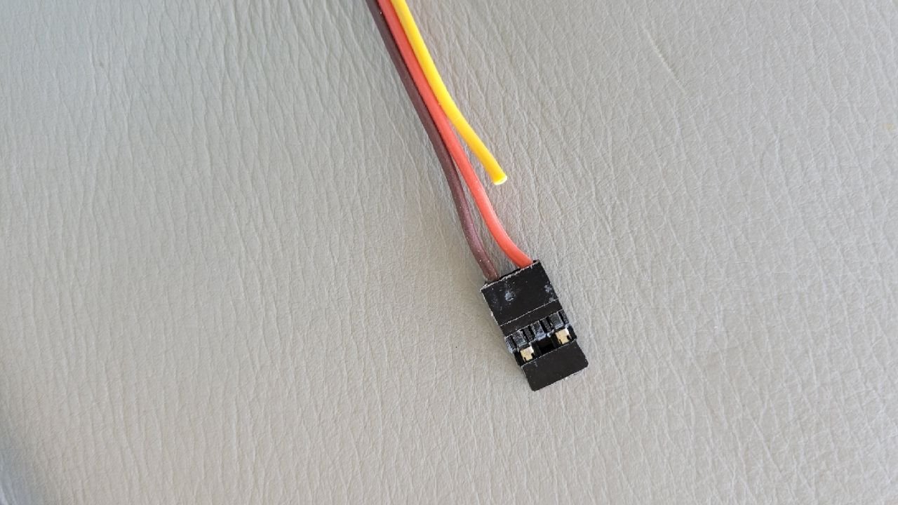
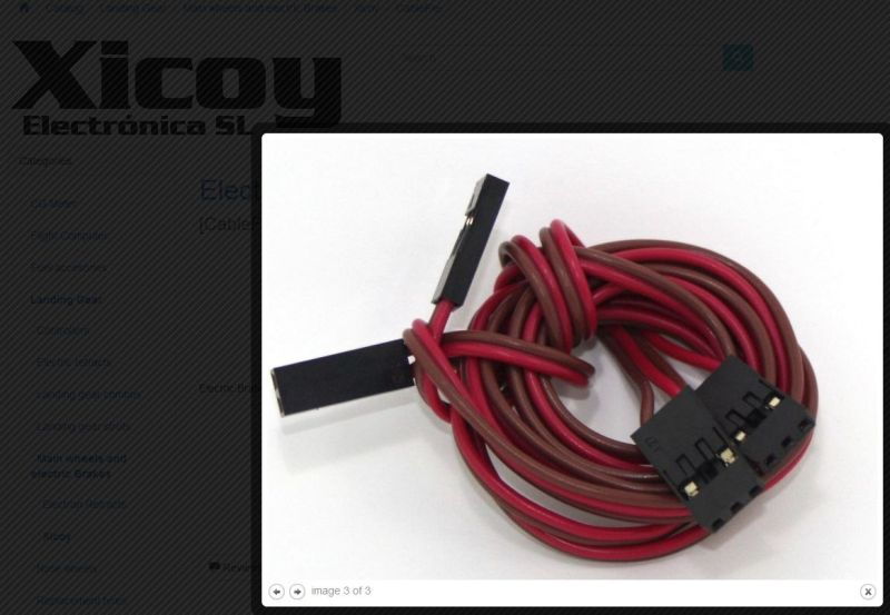
Not silly to ask. I was already quite fustrated when had this same problem. With 2-pin brake connector included with C&C kit they just didn't work. Luckily my friend gave me a hint. You propably need this cable or equivalent from 3-pin servo lead body combined with your current connectors.
/Jyri
/Jyri
09-15-2021, 06:39 PM
#479

My Feedback: (1)
Looking for some suggestions to troubleshoot the LG-15 with ER-120 gear on an Aerofoam L-39. The gear works perfect with the stock controller, but I cannot get the gear to open or close when the gear is fully open or closed. I can get the gear to cycle with the LG-15 once to the open or close position when I leave the gear partially open, but then the gear will not open nor close after than initial movement.
I have tried current limit ranging from 0.5-0.9a with a rewind time ranging from 0.1-0.2s. I see the voltage on the retract outputs across pins 1 and 3 during the gear sequencing. The ammeter shows max 0.85a on the main and nose retracts when I measure using the stock controller.
I am running 2s LiFe, so between 6.7-6.4v. That voltage works fine with the stock controller, which is also unregulated.
Any ideas?
Last edited by seattlebuoy; 09-15-2021 at 06:46 PM.
09-15-2021, 06:58 PM
#480
Senior Member
Little unclear on your voltage reading. Are you seeing the full battery voltage across the pins when activating the retract? Have you tried it with a 2s lipo or a fully topped off right off the charger li-fe which should be at 7.2v for a short period of time?
09-15-2021, 07:10 PM
#481

Looking for some suggestions to troubleshoot the LG-15 with ER-120 gear on an Aerofoam L-39. The gear works perfect with the stock controller, but I cannot get the gear to open or close when the gear is fully open or closed. I can get the gear to cycle with the LG-15 once to the open or close position when I leave the gear partially open, but then the gear will not open nor close after than initial movement.
I have tried current limit ranging from 0.5-0.9a with a rewind time ranging from 0.1-0.2s. I see the voltage on the retract outputs across pins 1 and 3 during the gear sequencing. The ammeter shows max 0.85a on the main and nose retracts when I measure using the stock controller.
I am running 2s LiFe, so between 6.7-6.4v. That voltage works fine with the stock controller, which is also unregulated.
Any ideas?
I have tried current limit ranging from 0.5-0.9a with a rewind time ranging from 0.1-0.2s. I see the voltage on the retract outputs across pins 1 and 3 during the gear sequencing. The ammeter shows max 0.85a on the main and nose retracts when I measure using the stock controller.
I am running 2s LiFe, so between 6.7-6.4v. That voltage works fine with the stock controller, which is also unregulated.
Any ideas?
 09-15-2021, 08:13 PM
#483
My Feedback: (1)
I am seeing full battery voltage across the pins. That was the range of voltages from a couple of different batteries. I tried a lipo at 7.6 and same bahavior. I can hear a brief motor movement and see the current percentage pulse on the LG15 display. This is with all voltages.
09-16-2021, 05:34 AM
#484
I used a separate 2S LiPo in one install because the 2S LiFe provided too low of a voltage. That low voltage caused a higher current condition tripping the current limiters in the LGC15. If I recall correctly, I was well over 1 amp on the limiters before the gear worked on 2S LiFe. Ever since I exclusively use 2S LiPo and all HV gear. 2S LiFe actually exceeds the limits of most low voltage servos anyway. Some folks may get away with 2S LiFe and LV gear. Some don't and may end up wondering why the plane crashed! Lower voltage = more current. More current typically = more heat. Electronics do not like heat.
I would measure the current and voltage using the OEM controller. Then set the current limits in the LGC15 to match. Or, you could just bump up the current limits one step at a time until they operate the gear and then bump it up one extra increment to make sure they will always work. It is a bit riskier this way, especially with LiFe. But, I have done it that way too. But that was using 2S LiPo.
I would measure the current and voltage using the OEM controller. Then set the current limits in the LGC15 to match. Or, you could just bump up the current limits one step at a time until they operate the gear and then bump it up one extra increment to make sure they will always work. It is a bit riskier this way, especially with LiFe. But, I have done it that way too. But that was using 2S LiPo.
09-16-2021, 06:42 AM
#485
My Feedback: (1)
I used a separate 2S LiPo in one install because the 2S LiFe provided too low of a voltage. That low voltage caused a higher current condition tripping the current limiters in the LGC15. If I recall correctly, I was well over 1 amp on the limiters before the gear worked on 2S LiFe. Ever since I exclusively use 2S LiPo and all HV gear. 2S LiFe actually exceeds the limits of most low voltage servos anyway. Some folks may get away with 2S LiFe and LV gear. Some don't and may end up wondering why the plane crashed! Lower voltage = more current. More current typically = more heat. Electronics do not like heat.
I would measure the current and voltage using the OEM controller. Then set the current limits in the LGC15 to match. Or, you could just bump up the current limits one step at a time until they operate the gear and then bump it up one extra increment to make sure they will always work. It is a bit riskier this way, especially with LiFe. But, I have done it that way too. But that was using 2S LiPo.
I would measure the current and voltage using the OEM controller. Then set the current limits in the LGC15 to match. Or, you could just bump up the current limits one step at a time until they operate the gear and then bump it up one extra increment to make sure they will always work. It is a bit riskier this way, especially with LiFe. But, I have done it that way too. But that was using 2S LiPo.
09-16-2021, 08:12 AM
#486
Sometimes new gear operators are tight fitting. I take mine apart and lube them with BVM's Dri-Lube and look for rough edges in the trunions and side plates, etc. Also, I had one set of gear that I ended up leaving the screws in the side-plates loose, but locktighted. It made a visible difference that I could see in the inline ammeter. Also used gear can be beat up or worn causing current spikes, etc. However, if the gear operates O.K. with the OEM controller, though, I think you are looking at the LGC15's current limiters activating.
On a side note: In the past, JP Gear operators have shown to be sensitive to over voltage. The JP ER - 120 used to be rated for 5-6 VDC. It may still be. There are claims that more than 7.5 VDC can burn out the motor. I have a VR in the supply for their gear. It is set at 7.5 VDC. But, ... I think JP may have fixed that with current products being rated for 2S LiPo.
On a side note: In the past, JP Gear operators have shown to be sensitive to over voltage. The JP ER - 120 used to be rated for 5-6 VDC. It may still be. There are claims that more than 7.5 VDC can burn out the motor. I have a VR in the supply for their gear. It is set at 7.5 VDC. But, ... I think JP may have fixed that with current products being rated for 2S LiPo.
09-16-2021, 08:46 AM
#487
My Feedback: (1)
Sometimes new gear operators are tight fitting. I take mine apart and lube them with BVM's Dri-Lube and look for rough edges in the trunions and side plates, etc. Also, I had one set of gear that I ended up leaving the screws in the side-plates loose, but locktighted. It made a visible difference that I could see in the inline ammeter. Also used gear can be beat up or worn causing current spikes, etc. However, if the gear operates O.K. with the OEM controller, though, I think you are looking at the LGC15's current limiters activating.
On a side note: In the past, JP Gear operators have shown to be sensitive to over voltage. The JP ER - 120 used to be rated for 5-6 VDC. It may still be. There are claims that more than 7.5 VDC can burn out the motor. I have a VR in the supply for their gear. It is set at 7.5 VDC. But, ... I think JP may have fixed that with current products being rated for 2S LiPo.
On a side note: In the past, JP Gear operators have shown to be sensitive to over voltage. The JP ER - 120 used to be rated for 5-6 VDC. It may still be. There are claims that more than 7.5 VDC can burn out the motor. I have a VR in the supply for their gear. It is set at 7.5 VDC. But, ... I think JP may have fixed that with current products being rated for 2S LiPo.
09-16-2021, 10:17 AM
#488
Senior Member
I have the 120's in a mini T one and there were some questions in the build thread about the voltage for them as some people were burning up retract motors. So some people put a BEC in line with the Rx 2s lipo. I did that as well and am running mine at 6.0 volts and have the controller somewhere around .6 or .7 amps. Should have mentioned that previously but thought I had the ER 005's which I have in a mini avanti.
09-16-2021, 10:20 AM
#489
Thread Starter
I used a separate 2S LiPo in one install because the 2S LiFe provided too low of a voltage. That low voltage caused a higher current condition tripping the current limiters in the LGC15. If I recall correctly, I was well over 1 amp on the limiters before the gear worked on 2S LiFe. Ever since I exclusively use 2S LiPo and all HV gear. 2S LiFe actually exceeds the limits of most low voltage servos anyway. Some folks may get away with 2S LiFe and LV gear. Some don't and may end up wondering why the plane crashed! Lower voltage = more current. More current typically = more heat. Electronics do not like heat.
I would measure the current and voltage using the OEM controller. Then set the current limits in the LGC15 to match. Or, you could just bump up the current limits one step at a time until they operate the gear and then bump it up one extra increment to make sure they will always work. It is a bit riskier this way, especially with LiFe. But, I have done it that way too. But that was using 2S LiPo.
I would measure the current and voltage using the OEM controller. Then set the current limits in the LGC15 to match. Or, you could just bump up the current limits one step at a time until they operate the gear and then bump it up one extra increment to make sure they will always work. It is a bit riskier this way, especially with LiFe. But, I have done it that way too. But that was using 2S LiPo.
Last edited by Tip22v; 09-16-2021 at 11:18 AM.
01-12-2022, 07:21 PM
#490
Member
I think your "Lower Voltage = Higher Amperage" theory is the most likely scenario with this issue. This is one of the reasons I like to run a VR into my LG15 (I also regulate to 7.5v), a consistent voltage input means the amperage draw on the retracts will be consistent with each cycle, and since the cutoff amperage is fixed (to whatever you have it set to), there is no variation as voltage on the flight battery drops during flight. E.g. If your flight begins at 7.2v (2S LiFe) when you put the gear up your gear will draw a certain amount of Amps to produce the needed wattage (power) to cycle your gear (Watts = Voltage x Amperage). Towards the end of the flight if your battery voltage has dropped to 6.8v the gear will need to draw more amperage to maintain the needed wattage. Anyway, regulating the input voltage to the LG15 removes this variation and allows the gear to cycle more consistently. All that being said, most gear motors can handle the slight variation in Cut0ff Amperage needed to account for this variation, however, I have burned out JP gear motors in the past, but have not burned up a single gear motor in four years since I started using a VR on LG15. -Tom
 01-13-2022, 07:15 AM
#491
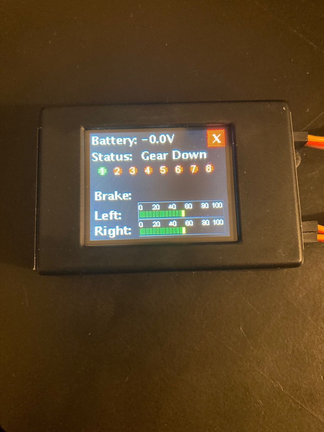
The one question I have is; why does the battery voltage say 0.0 volts? If I was testing, I would have the battery and gear plugged in. From the picture, it does not look like you have fully simulated the conditions necessary to do any testing (i.e. plug in the battery and gear). You are just running part of the controller. The brakes and gear motors do NOT operate off the power supplied by the connections to the receiver. But once you fully simulate the conditions for testing, and if you still see the 50% on the screen, I offer the below information:
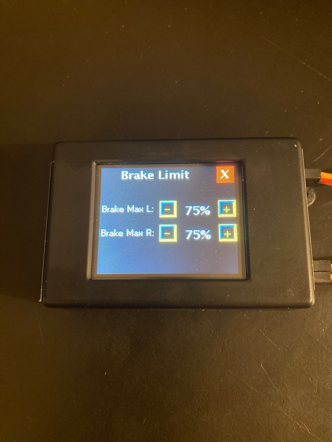
Try rotating the tires with the brake fully on and see what happens. It does not take as much power when the tires are NOT rotating. It might not even take 75% to totally lock them up. Also, if you simulate a skid to the side, you will see the power go up to the limit on the side needed to straighten the plane out. It should go up to but not beyond that limit. Also, your ABS and gyro settings can also have some interaction with the power applied to the brakes. But in your case, the 75% is the "hard" limit. Typically, all I ever used that screen for was to match the brakes. The prolinks I had on the Ultraflash had one brake that always worked better than the other. One would lock up before the other. So, I just cut the power back a little on the offending brake to match them up when the brake was fully applied.
Remember the battery supplies the power to the brakes and gear motors. The receiver connection power only operates the controller. These two power supplies are isolated from each other in the controller.
01-13-2022, 08:25 PM
#492
Member
Thanks Stan. It's not as organized as I would like but most of the needed info is there. I still need to add a step 7 that outlines how to "teach" your radio settings (Gear UP, Gear DOWN, Min Brakes, Max Brakes) and step 8 that describes how to set the cutoff amperage for your retracts. Hopefully, I will get to that later this week.
While working on this I discovered another potential issue. If you are using another gyro for pitch, roll, and yaw stabilization (e.g. iGyro, Cortex etc.) then you need to make sure the rudder channel feeding the LG15 is NOT stabilized. If it is, you will be in a situation where you have one gyro feeding another gyro, which essentially will disable (not sure to what degree yet) the gain settings on the LG15.
While working on this I discovered another potential issue. If you are using another gyro for pitch, roll, and yaw stabilization (e.g. iGyro, Cortex etc.) then you need to make sure the rudder channel feeding the LG15 is NOT stabilized. If it is, you will be in a situation where you have one gyro feeding another gyro, which essentially will disable (not sure to what degree yet) the gain settings on the LG15.
01-14-2022, 06:04 AM
#493
Thread Starter
I do have a Cortex Pro to control pitch, roll and yaw. Currently my rudder signal goes from channel 5 on the receiver to the input of the Cortex, then rudder output from the Cortex to a blue box that came in the plane. The rudder and steering servos then plug into this blue box. I would assume the Cortex is stabilizing both the rudder and steering servos. What if I used a Y-lead from the receiver and plugged one of the Y leads into the Cortex and the other Y-lead into the Steering In port of the LG15. Keep the rudder servo plugged into the blue box as it is but remove the steering servo from the blue box and plug it into the steering out port of the LG15? This would keep the steering servo from going through the Cortex and being stabilized would it not and the LG15 would work as it should?
I also use Jeti EX bus to connect Rx to the CortexPro, in these cases I just go into the CortexPro programming and set the Gain to zero for the nose steering output so that the LGC-15 gets an unstablized signal for nose steering input.
Last edited by Tip22v; 01-14-2022 at 06:09 AM.
07-19-2022, 11:03 AM
#494
Tom, thanks for starting this thread! Martin�s video is also very helpful. I bought a LG15 several months ago and didn�t use it due to complexity and lack of good instructions/manual.
I am now ready to use it in my Baja Hobby F15. Forgive me if I missed this but the pins/polarity on the side where the battery input is located are not marked. I am referring to Brake R, Brake L, Mains R, Mains L & Nose inputs.

I am now ready to use it in my Baja Hobby F15. Forgive me if I missed this but the pins/polarity on the side where the battery input is located are not marked. I am referring to Brake R, Brake L, Mains R, Mains L & Nose inputs.
07-19-2022, 11:41 AM
#495
Senior Member
Tom, thanks for starting this thread! Martin’s video is also very helpful. I bought a LG15 several months ago and didn’t use it due to complexity and lack of good instructions/manual.
I am now ready to use it in my Baja Hobby F15. Forgive me if I missed this but the pins/polarity on the side where the battery input is located are not marked. I am referring to Brake R, Brake L, Mains R, Mains L & Nose inputs.
I am now ready to use it in my Baja Hobby F15. Forgive me if I missed this but the pins/polarity on the side where the battery input is located are not marked. I am referring to Brake R, Brake L, Mains R, Mains L & Nose inputs.
chrome-extension://efaidnbmnnnibpcajpcglclefindmkaj/http://www.xicoy.com/LG15.pdf
or download it here.... https://www.xicoy.com/catalog/produc...roducts_id=414
07-19-2022, 12:19 PM
#496
Thread Starter
Tom, thanks for starting this thread! Martin�s video is also very helpful. I bought a LG15 several months ago and didn�t use it due to complexity and lack of good instructions/manual.
I am now ready to use it in my Baja Hobby F15. Forgive me if I missed this but the pins/polarity on the side where the battery input is located are not marked. I am referring to Brake R, Brake L, Mains R, Mains L & Nose inputs.
I am now ready to use it in my Baja Hobby F15. Forgive me if I missed this but the pins/polarity on the side where the battery input is located are not marked. I am referring to Brake R, Brake L, Mains R, Mains L & Nose inputs.
 . Tom
07-19-2022, 01:55 PM
. Tom
07-19-2022, 01:55 PM
#497
The Pin 1 and 3 thing is the only thing in the manual that is missing. If you follow the manual, the LGC will work. It may take some discovery time and effort as you fine tune it. But fine tuning it will give you a great LGC. The first time I set one up I laid the gear, LGC and a spare RXer, etc. all out on the bench and played with it. Once I had it all working, then I installed the gear, LGC, etc. then it worked flawlessly w/o fishing around inside the plane. Also, it should be expected that you will spend some time tweaking the gyro, brake power levels, etc.
Attached are a couple files that may help you.
Attached are a couple files that may help you.
07-19-2022, 02:03 PM
#498
Senior Member
The Pin 1 and 3 thing is the only thing in the manual that is missing. If you follow the manual, the LGC will work. It may take some discovery time and effort as you fine tune it. But fine tuning it will give you a great LGC. The first time I set one up I laid the gear, LGC and a spare RXer, etc. all out on the bench and played with it. Once I had it all working, then I installed the gear, LGC, etc. then it worked flawlessly w/o fishing around inside the plane. Also, it should be expected that you will spend some time tweaking the gyro, brake power levels, etc.
Attached are a couple files that may help you.
Attached are a couple files that may help you.
07-20-2022, 12:03 PM
#500
the middle pin is not used, the two outside pins are neg and pos. Which way you plug them in is dependent on the config of your retract motors, you plug them in so that your retracts all move in the same direction when activated. Brake polarity does not matter. Hope this helps. Tom
. Tom