


CARF Mig-15 questions
 05-29-2019, 02:35 PM
#1

Guys,
I'm looking for some help with a CARF Mig-15.
First, I'm looking for struts (only) for the CARF Mig-15. I know that Intairo has the on their website. Has anyone ordered from Intairco lately? Do they deliver?
Second, does anybody know what the diameter of the main wheels are for the CARF Mig-15.
Any info. would be helpful.
Thanks!
Bob
 05-29-2019, 10:10 PM
#3


I can get you the wheel diameters tomorrow if no one beats me to it. I ordered from Intakrco about a year ago, no issues. I’ve been really tempted to upgrade my MiG to the electric gear, but would still need air for doors brakes and speed brakes without other mods so that’s kept me from hitting the order button so far.
05-30-2019, 02:42 AM
#4

Guys,
I'm looking for some help with a CARF Mig-15.
First, I'm looking for struts (only) for the CARF Mig-15. I know that Intairo has the on their website. Has anyone ordered from Intairco lately? Do they deliver?
Second, does anybody know what the diameter of the main wheels are for the CARF Mig-15.
Any info. would be helpful.
Thanks!
Bob
I'm looking for some help with a CARF Mig-15.
First, I'm looking for struts (only) for the CARF Mig-15. I know that Intairo has the on their website. Has anyone ordered from Intairco lately? Do they deliver?
Second, does anybody know what the diameter of the main wheels are for the CARF Mig-15.
Any info. would be helpful.
Thanks!
Bob
IMHO the original struts are a waste of money and NO GOOD.
You get only 5mm of travel (!!!) that when it runs out you stress direct the retract wing woods and you will damage your wing stracture.
On top of that the small springs (scale look) can not lift the airframe leaving you with no suspension anyway.
The main wheels is another heavy pain.1KG both .
I strongly recommend you look to a more functional struts than this.The doors will hide them anyway and you will save the failures .
My 2c
...some more photos here mig-15 reply
Last edited by DelGatoGrande; 05-30-2019 at 02:45 AM.
05-30-2019, 06:44 AM
#5
I can get you the wheel diameters tomorrow if no one beats me to it. I ordered from Intakrco about a year ago, no issues. I�ve been really tempted to upgrade my MiG to the electric gear, but would still need air for doors brakes and speed brakes without other mods so that�s kept me from hitting the order button so far.
I'm planning on going all electric - with servo or linear actuators for the doors and speed brake. I'm going to go with the Electron Evo 50 gear units, that's why I only want the struts.
Bob
05-30-2019, 06:46 AM
#6
I have loged in many flights on my Mig for many years until i sold it two years ago...i do miss it tho .
IMHO the original struts are a waste of money and NO GOOD.
You get only 5mm of travel (!!!) that when it runs out you stress direct the retract wing woods and you will damage your wing stracture.
On top of that the small springs (scale look) can not lift the airframe leaving you with no suspension anyway.
The main wheels is another heavy pain.1KG both .
I strongly recommend you look to a more functional struts than this.The doors will hide them anyway and you will save the failures .
My 2c
...some more photos here mig-15 reply
Attachment 2264285
 05-30-2019, 08:00 AM
#7
He probably had those struts, and he's right that they have painfully little shock absorbing function, but these were/are popular airplanes and people aren't busting wings open left and right. The prior owner of mine did reinforce the gear box, and I also just last week fit some stronger springs into the struts as well. Others have added external springs to add with suspension. I've never heard of anyone use another brand of strut beyond the Intaircos (other than the 1st gen design you mention).
I did manage to lose the spring out of my nose strut and cannot find an appropriate replacement that both fits inside but isn't so tight it binds against the pin. But it also doesn't really need anything as there's nearly no weight/load on the nose. I put a piece of tygon in there for now.
I did manage to lose the spring out of my nose strut and cannot find an appropriate replacement that both fits inside but isn't so tight it binds against the pin. But it also doesn't really need anything as there's nearly no weight/load on the nose. I put a piece of tygon in there for now.
05-30-2019, 06:32 PM
#8
I measured the mains at 4.5”. I guess I could have just looked on Intairco’s site, as these are the MiG wheels:
https://www.intairco.net/wheels-brak...-air-electric/
https://www.intairco.net/wheels-brak...-air-electric/
Last edited by Auburn02; 05-30-2019 at 06:34 PM.
05-30-2019, 07:28 PM
#9
I measured the mains at 4.5�. I guess I could have just looked on Intairco�s site, as these are the MiG wheels:
https://www.intairco.net/wheels-brak...-air-electric/
https://www.intairco.net/wheels-brak...-air-electric/
i guess its time to order from Intairco...
thanks!
Bob
05-16-2021, 05:26 AM
#11
My turn for a random question, for anyone who built this from a kit (version 2), how was the pipe installed? The follow up to that is can it be removed? On mine the bell mouth is riveted to the pipe but even after drilling off the rivets and removing the bell and lower bypass, I can’t get the pipe out due to the angle needed and the interference of formers and/or the glued rear hatch section. I assume it’s a tapered pipe, doesn’t want to slide out the tail either. I can work around it if needed, just want to clean up and telling some things in the tail section and would be nice to have the pipe out if possible.
05-20-2021, 10:31 AM
#12
My turn for a random question, for anyone who built this from a kit (version 2), how was the pipe installed? The follow up to that is can it be removed? On mine the bell mouth is riveted to the pipe but even after drilling off the rivets and removing the bell and lower bypass, I can�t get the pipe out due to the angle needed and the interference of formers and/or the glued rear hatch section. I assume it�s a tapered pipe, doesn�t want to slide out the tail either. I can work around it if needed, just want to clean up and telling some things in the tail section and would be nice to have the pipe out if possible.
I have a solution that I implemented that you could probably use. I'll get some pictures as soon as I can - on a *really boring* zoom right now...
Bob
05-20-2021, 11:33 AM
#13
Thanks Bob - mine being already built before I acquired it, that back hatch is glued on quite well - I haven't looked closely to see if the angles would work, but my thought was if I ever really needed to get it out I could possibly cut out the top of the main former and make up a doubler/joiner brace like is so common on so many models that bolts into place. Curious if that's your solution, or if you just came up with a way to not have to glue the rear hatch section on. Definitely follow up with pics if you can, I'm curious.
As it turns out I was able to do everything I needed in the tail even with the pipe still in (and I have the cuts on my hands/forearms to prove it). Now I just have to reinforce the fuel tank seam that blew open leading me to this mess and I'll be back in business.
As it turns out I was able to do everything I needed in the tail even with the pipe still in (and I have the cuts on my hands/forearms to prove it). Now I just have to reinforce the fuel tank seam that blew open leading me to this mess and I'll be back in business.
05-20-2021, 11:34 AM
#14
OK, boring zoom over...
I measured my stock CARF pipe and it tapers from 3 7/8" diameter at the back to 4 1/4" diameter in the front. Mine can not be removed from the aft end of the fuselage - mainly because of the speed brake pockets.
As I said, I noticed that there was no way to remove the pipe from the fuselage if you glue the aft hatch to the fuselage as the directions state. In addition, I didn't like how the hatches were separated and that the aft cockpit needs to be removable to get to the engine as I want to install a sliding canopy.
To fix that, I modified how the hatches work as you can see from the pictures below. The canopy section is bolted on and there is an aft hatch to get to the engine and a forward hatch for batteries. I also extended my intakes to the rear to make more room for a cockpit and made them removable in order to get to the fuel tank.
However, none of this actually fully solved the problem with getting the pipe out (or the intakes out either). To solve that problem, I made the top center of the main former removable. You can see that in the last picture. I cut the section out with a zona saw so there wasn't much "curf" lost and the piece fits back fairly snugly. It is held in place by two carbon fibre plates on each side with 6 6-32 bolts on each side.
Some might question doing that, but trust me, the piece removed fits tightly and is loaded in compression during positive G loading and the carbon fiber plates with the 6-32 bolts are not going anywhere. You'll rip the wing off before that modified former even moves...
Bob
Last edited by rhklenke; 05-20-2021 at 11:36 AM.
05-20-2021, 02:34 PM
#15
Cool, Bob - can you expand/add more pictures to go with this comment?
I didn't actually have a rear intake joiner in mine at all, but ordered one and added it just a few months ago. It does make things a much tighter fit, but I couldn't stand looking in the nose and seeing wires and tube and other innards. And as you mention, it makes fitting a full cockpit about impossible. Curious to see how you modified that. Mine is removable at least, it's actually held in place with no fasteners at all but is secured snugly by the front intake sections and the engine bypass.
I also extended my intakes to the rear to make more room for a cockpit and made them removable in order to get to the fuel tank.
I didn't actually have a rear intake joiner in mine at all, but ordered one and added it just a few months ago. It does make things a much tighter fit, but I couldn't stand looking in the nose and seeing wires and tube and other innards. And as you mention, it makes fitting a full cockpit about impossible. Curious to see how you modified that. Mine is removable at least, it's actually held in place with no fasteners at all but is secured snugly by the front intake sections and the engine bypass.
05-22-2021, 07:57 AM
#17
OK, so I decided to extend the intakes to the rear as far as I though was practical. I made these "quick and dirty" molds to make extensions.

Here you can see the extensions in place and the resulting move of the intakes to the rear. I had to (of course) cut off some of the back of the intake when I moved it back.
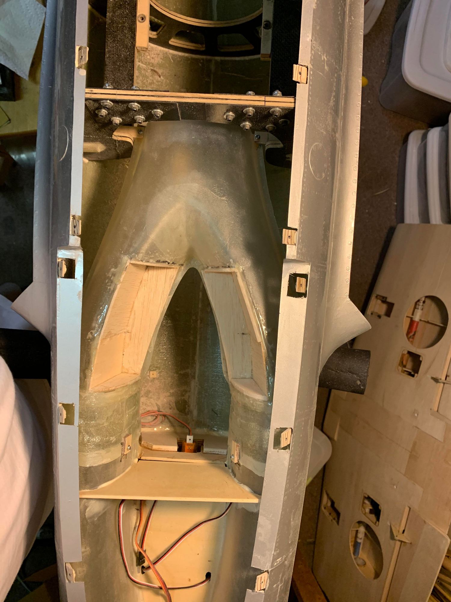
Actually, I think I should have moved them back some more, but I didn't want to re-make my molds. It turns out that I still needed more space for the full-depth cockpit seat, so I extended the back of the cockpit into the intakes.
Here you can see the extensions in place and the resulting move of the intakes to the rear. I had to (of course) cut off some of the back of the intake when I moved it back.
Actually, I think I should have moved them back some more, but I didn't want to re-make my molds. It turns out that I still needed more space for the full-depth cockpit seat, so I extended the back of the cockpit into the intakes.
05-22-2021, 08:02 AM
#18
Here you can see how the cockpit extends into the intakes in the seat area.

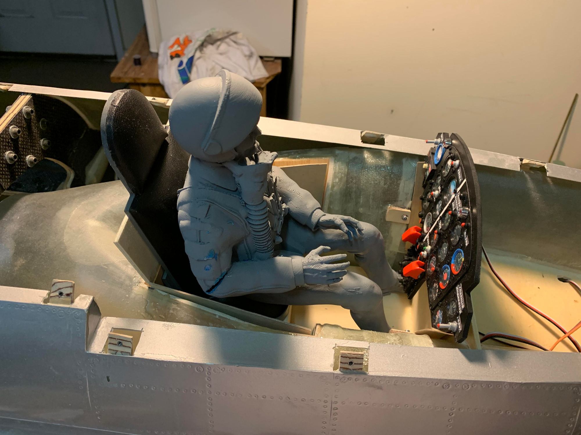
You can see the extensions into the intakes a little bit from the front, but you have to look closely. I'm going to fair them in so that they don't cause too much turbulance in the inlet air flow, but our turbines don't really need much air and they are pretty robust to airflow disruptions (unlike an EDF), so it should be fine.


You can see the extensions into the intakes a little bit from the front, but you have to look closely. I'm going to fair them in so that they don't cause too much turbulance in the inlet air flow, but our turbines don't really need much air and they are pretty robust to airflow disruptions (unlike an EDF), so it should be fine.

 05-24-2021, 06:53 PM
#22
There is an old build thread on this forum somewhere that had some good pictures of a well done cockpit and sliding canopy, but last time I looked for it the post was still there but the pics were gone. Shame. I'll see if I can find it.
