T-One Models 2.7m F-22 build


 02-01-2020, 07:22 PM
#77

Thread Starter

sorry about the twin builds I thought about today but I use your build to make sure I’m doing mine correct plus I have the twin and you’re doing the single. So a thread for each
02-02-2020, 12:09 PM
#78
Thread Starter
Anyone have the the issue with the rudder drive T end on the rudder being too small for the groove on the servo T joint? I have one that has about a 1/4 of play, the other has what I would consider normal play. If so how they heck did or would you fix this?
02-02-2020, 08:33 PM
#80
Thread Starter
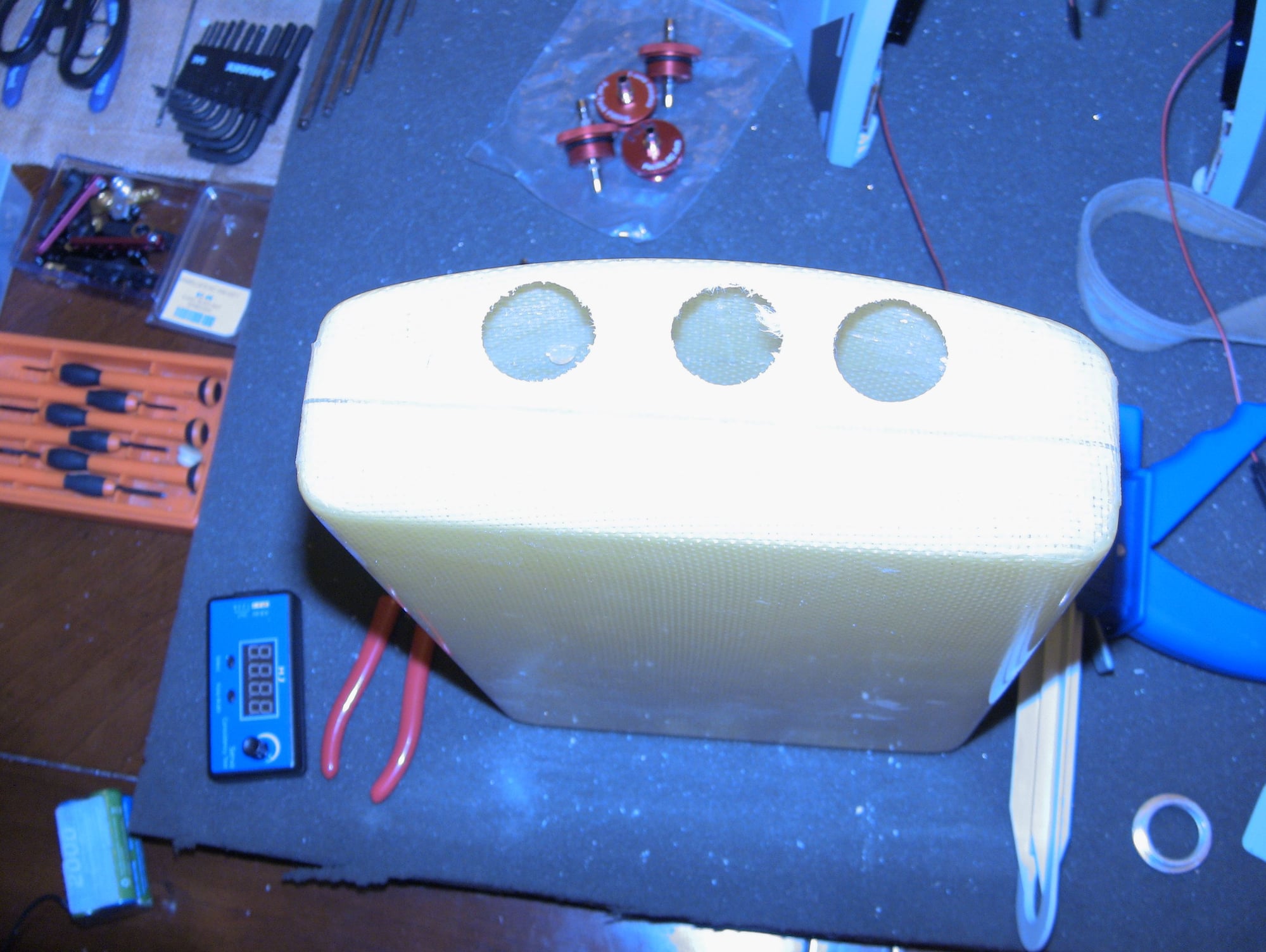
You will need to open up the top area to get the servos in, I put the rudders on an traced with a pencil so I didnt cut past what the rudders will cover.

Two M166TS power plants ready to install when I can figure out how

Blocks to lift rudder servos

Blocks glued in

Steel adapter

Be sure to trace the rudder outline so u dont cut past what is covered by the rudder itself

Done, any only a slight headache

Bottom covers

Last edited by FenderBean; 02-02-2020 at 08:38 PM.
02-02-2020, 11:30 PM
#81

I tried visualising the spatial gap with some blue tack or foam tape, and then attempted to fill the gap with kneaded metal epoxy. Didn't work, it won't stick.
Short of a bendy scope, I couldn't make out what's exactly causing this free play.
I minimised whatever free play now there was by making sure the servo wasn't able to rock sideways along the height axis, which helped some.
02-03-2020, 05:05 AM
#82
Thread Starter
So I had the same bugbears, the odd rudder servo mount angle and there was some play for the left rudder due to whatever fit issue there was.
I tried visualising the spatial gap with some blue tack or foam tape, and then attempted to fill the gap with kneaded metal epoxy. Didn't work, it won't stick.
Short of a bendy scope, I couldn't make out what's exactly causing this free play.
I minimised whatever free play now there was by making sure the servo wasn't able to rock sideways along the height axis, which helped some.
From what David said about his and now you it would appear to be a manufacture issue
 02-03-2020, 09:14 AM
#85
Thread Starter
you would think they would have one file to manufacture both ends but they could have two with some slight measurement issue. Thanks for the help
 02-03-2020, 11:03 AM
#88
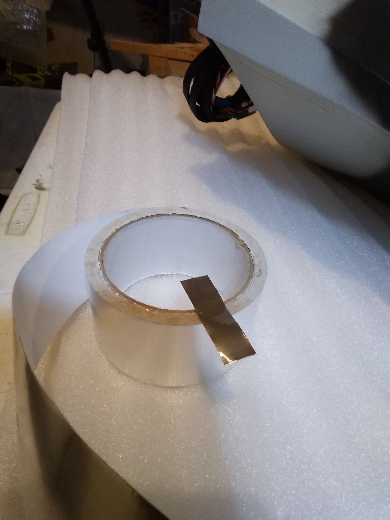
got the other wing done yesterday. Time to move up onto other parts. Not sure if I�m going to use the new fuel tanks or just install my old ones. Nothing wrong with them.
 02-03-2020, 07:21 PM
#94
Nice! I think this is a good idea, especially if it is real metal tape and won't compress too much due to the pin force on it. I'll try this out. Thanks!
02-03-2020, 09:01 PM
#95
Thread Starter
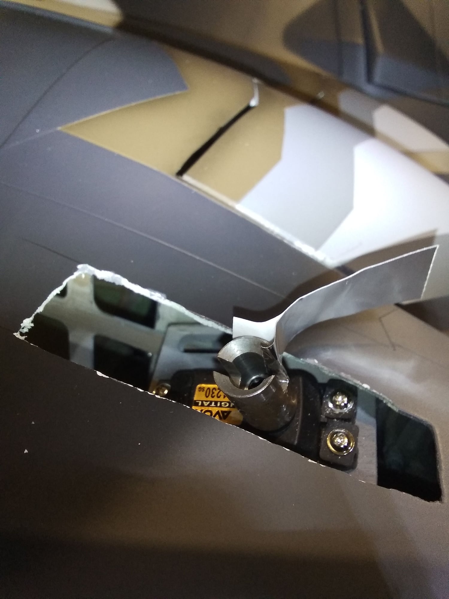
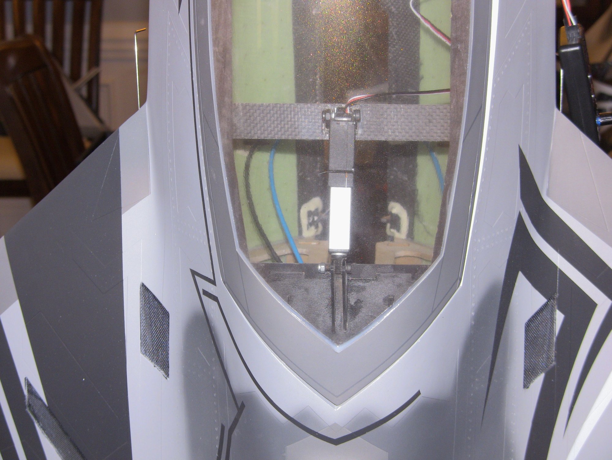
very little work today, I had a full day of other things getting in the way. I did switch gears a bit this evening and did the canopy open and close actuator. I simply removed the two tabs on the cross beam they installed for what I guess would have been an air cylinder, my kit was missing this but I planned to use my own setup. I added a 30 mm stroke Actuonix Linear servo, I have been using and selling these for a few years now. They are plug n play and work just like a regular servo and can be adjusted like servo via the radio. I went with the 210:1 gear ratio(18 lbs) since its a much higher torque but since it lifts real easy and not very heavy I may just use the 100:1 or even the 50:1. Lower ratio is faster but has less torque but the canopy has no force on the actuator once down a locked. The hinge needs a few mm removed from the rear part of the frame to allow for full extension, the amount open is very scale from the pictures I could find.
Sorry for the vertical picks, the jet was worked on while standing in the corner.
Oh and I will be removing the front air cylinder they glued to the canopy frame for a lock. I am going to use a 20mm stroke Linear actuator which very small, about the size of a micro servo.
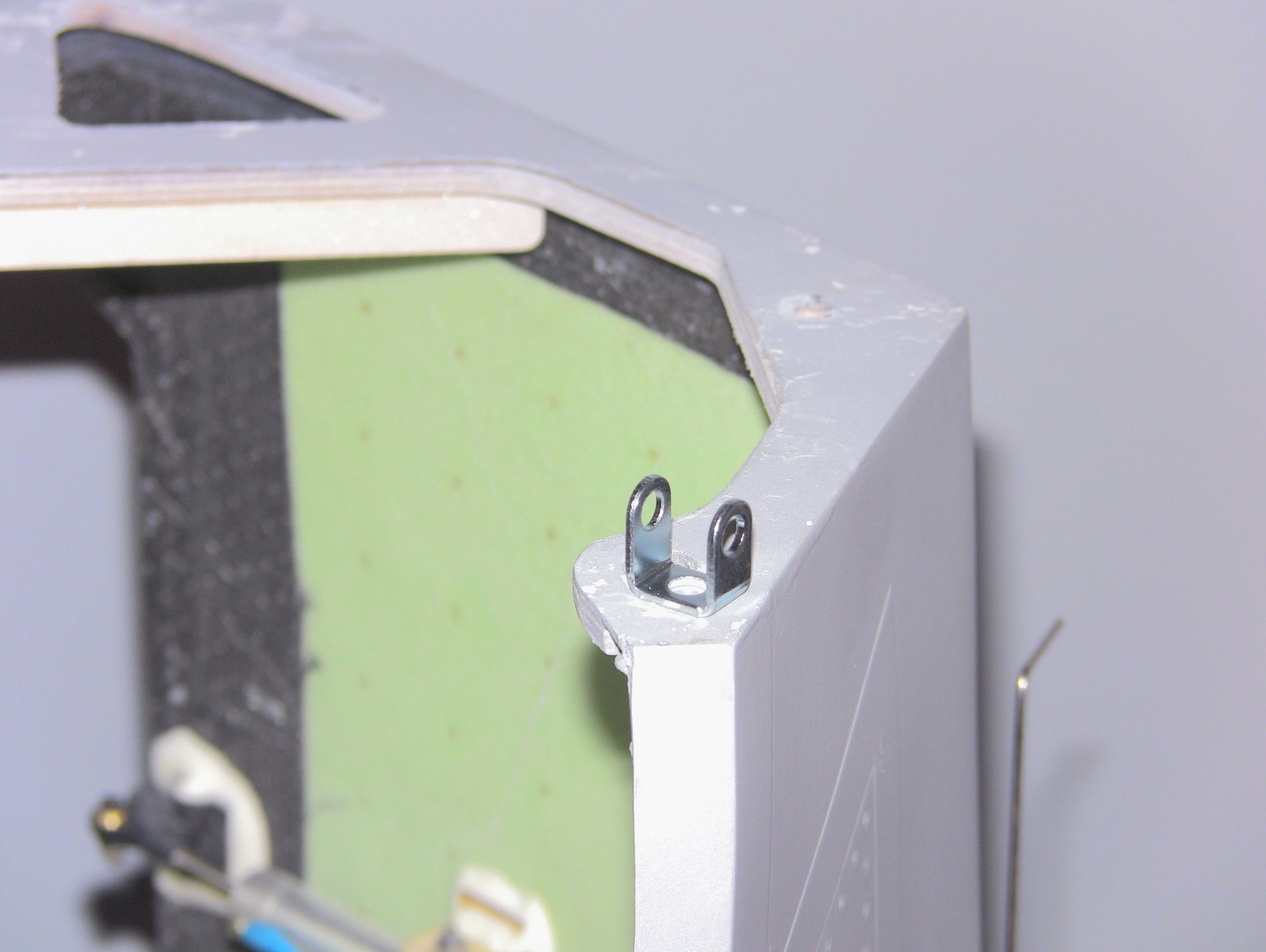
Metal mount bracket, supplied with the actuator

Installed on cross beam
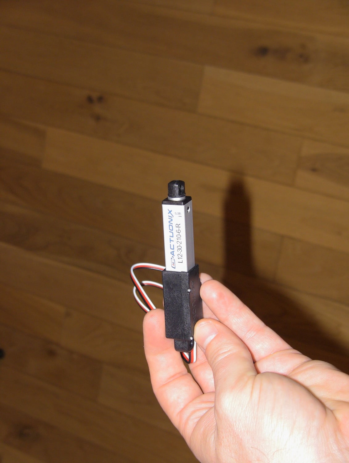
Actuonix 30mm Linear Actuator


BAM! on less valve and air leak to worry about!


Sorry for the vertical picks, the jet was worked on while standing in the corner.
Oh and I will be removing the front air cylinder they glued to the canopy frame for a lock. I am going to use a 20mm stroke Linear actuator which very small, about the size of a micro servo.
Metal mount bracket, supplied with the actuator
Installed on cross beam
Actuonix 30mm Linear Actuator
BAM! on less valve and air leak to worry about!
02-04-2020, 04:35 PM
#96
Thread Starter
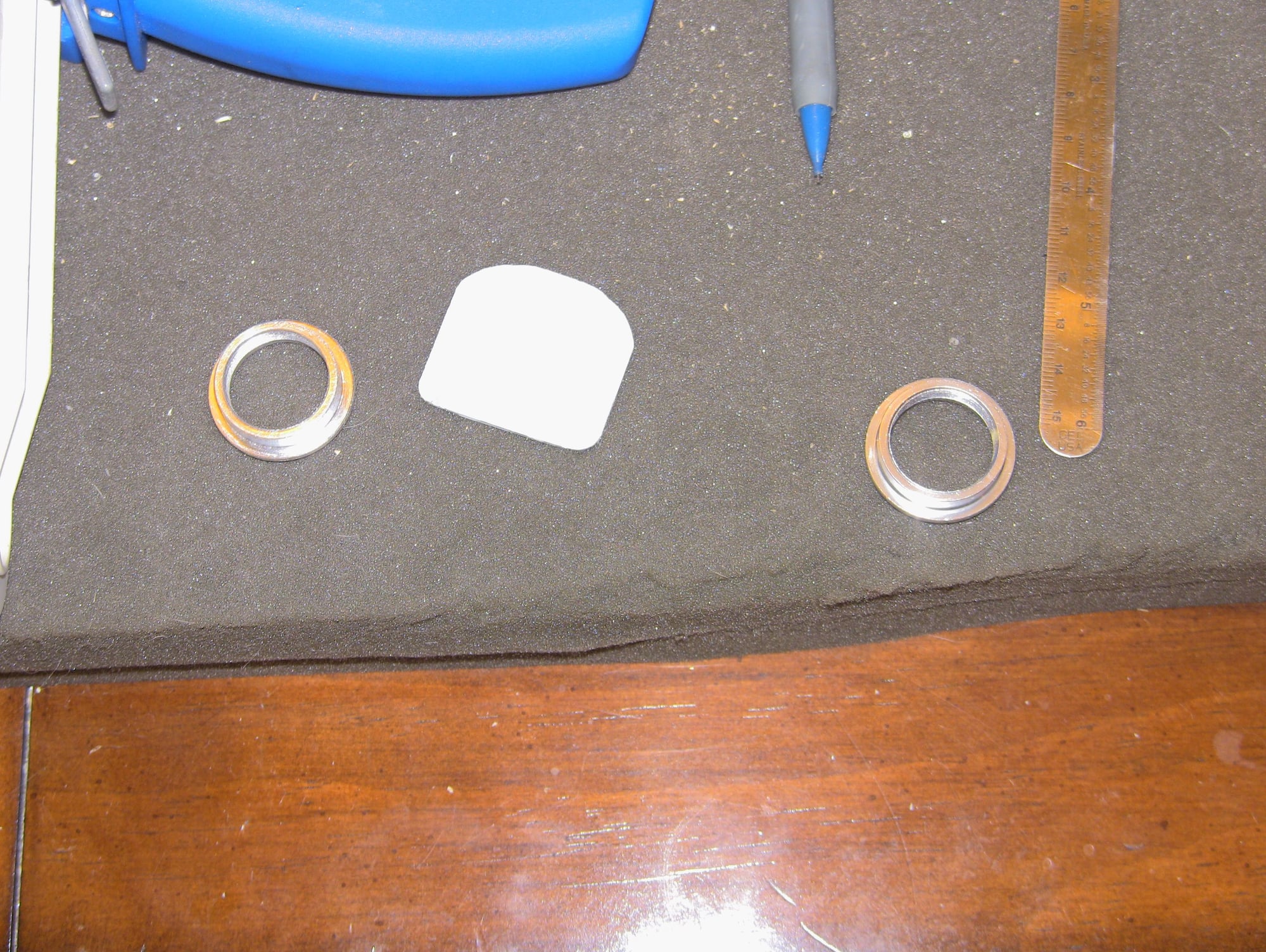
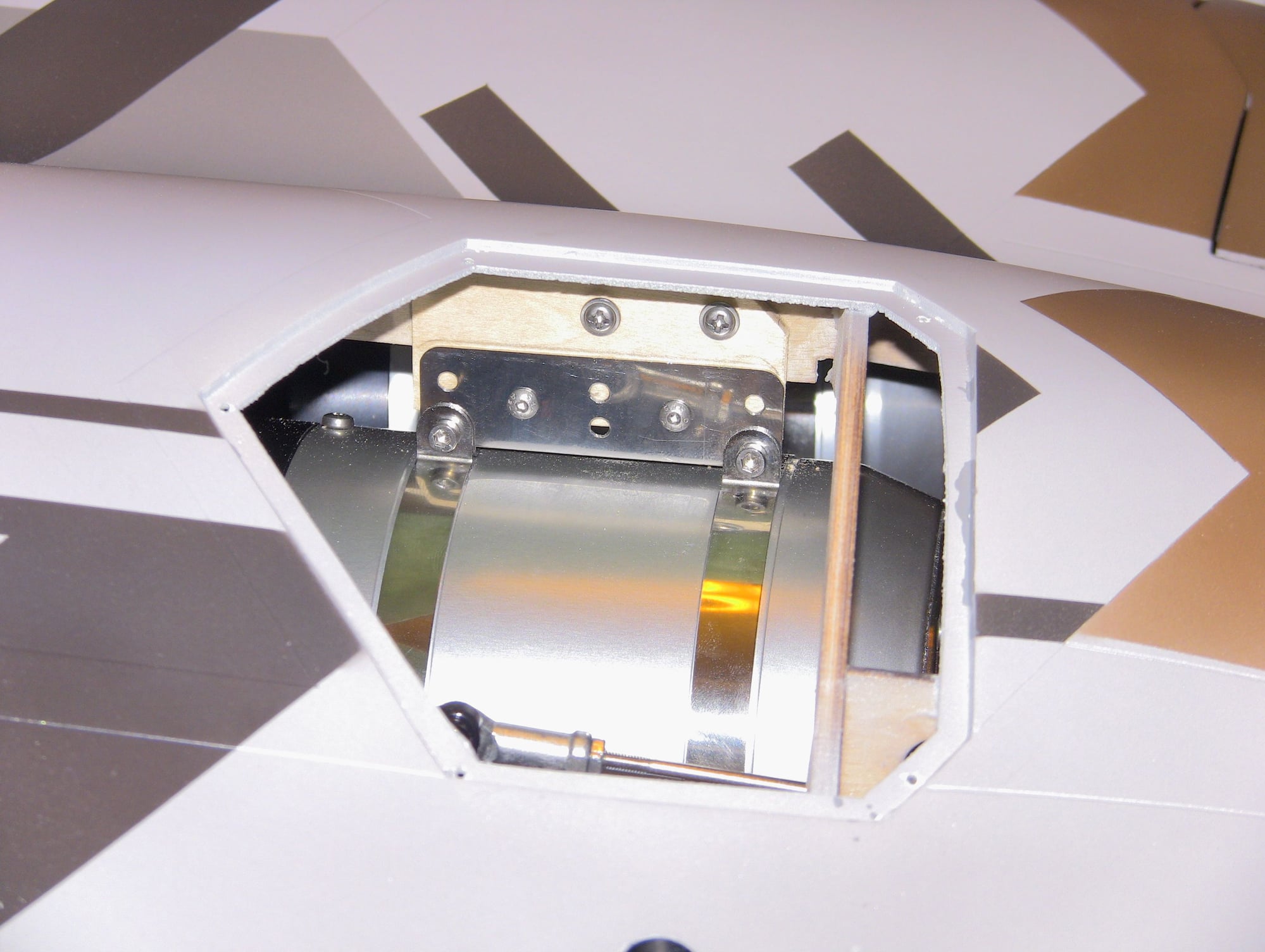
Well today was another slow day the canopy install was a rough one, its hard to get the proper alignment to make the rear section clear while making the front align. When the installed bulkhead is off a hair it makes it much harder, but I got and in the pictures you will see two washers on the right side I used align the canopy. The linear servo works great and I am uploading a video going over the work so far.
I removed the stock air cylinder lock and will be using a second Actuonix 30mm stroke actuator for the lock but mine will be mounted to the nose instead of the canopy.
I have been putting off the motor install just going to be a lot of trial and error so I skipped on to some easier things.
https://www.youtube.com/watch?v=gx2o...ature=youtu.be

This is the factory lock, I removed it and will add another Linear servo

Removed a small amount of material for clearance


PAIN in the but I spent all afternoon on four screws!
Closed

Open

All the required items for the nose steering

Completed, the factory had the light bracket on backwards scissors go aft by the way
I removed the stock air cylinder lock and will be using a second Actuonix 30mm stroke actuator for the lock but mine will be mounted to the nose instead of the canopy.
I have been putting off the motor install just going to be a lot of trial and error so I skipped on to some easier things.
https://www.youtube.com/watch?v=gx2o...ature=youtu.be
This is the factory lock, I removed it and will add another Linear servo
Removed a small amount of material for clearance
PAIN in the but I spent all afternoon on four screws!
Closed
Open
All the required items for the nose steering
Completed, the factory had the light bracket on backwards scissors go aft by the way
02-05-2020, 01:58 PM
#97
Thread Starter
Managed to get the motors installed, while not super hard but it takes some thought and based on your motor will be trial and error. I suggest watching the video explaining my method and if you have any questions let me know. Trying to explain what I did would take more than I would like to type.
Nose wheel is in as well, pretty simple I had to dremel some areas for clearance but nothing that shows when doors are closed.
I also made a small mount for the canopy lock actuator and its currently curing and once dry I will hysol the brass tube guides in the nose and canopy. Then the fun begins, the equipment and fuel system install!
Video is uploading on my youtube channel


Going to be different for each turbine, wider are the bottom

Johhny Five alive!!!!


Actuonix 30mm stroke actuator

Nose wheel is in as well, pretty simple I had to dremel some areas for clearance but nothing that shows when doors are closed.
I also made a small mount for the canopy lock actuator and its currently curing and once dry I will hysol the brass tube guides in the nose and canopy. Then the fun begins, the equipment and fuel system install!
Video is uploading on my youtube channel
Going to be different for each turbine, wider are the bottom
Johhny Five alive!!!!
Actuonix 30mm stroke actuator
02-05-2020, 04:47 PM
#98
02-05-2020, 08:35 PM
#100
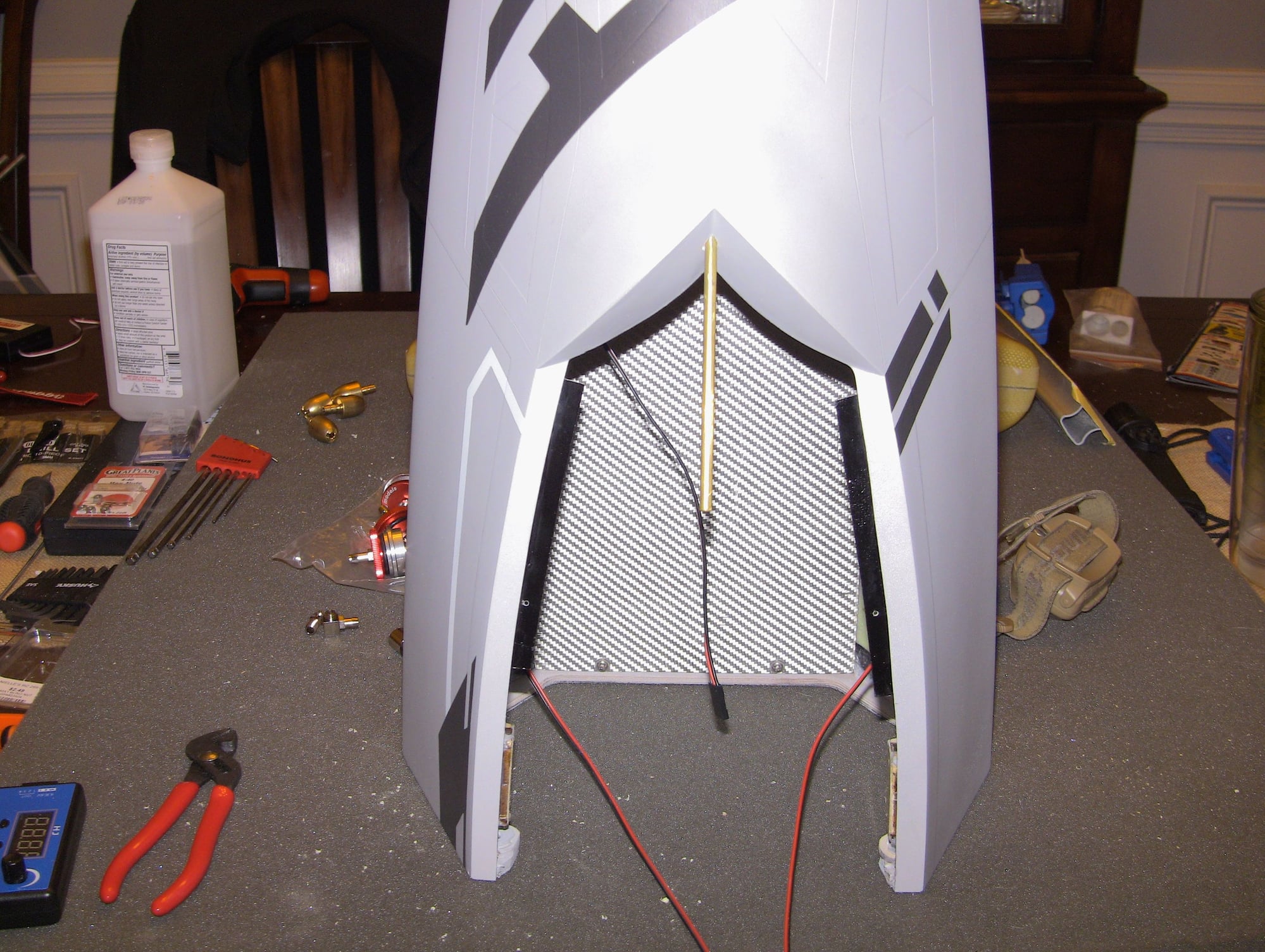
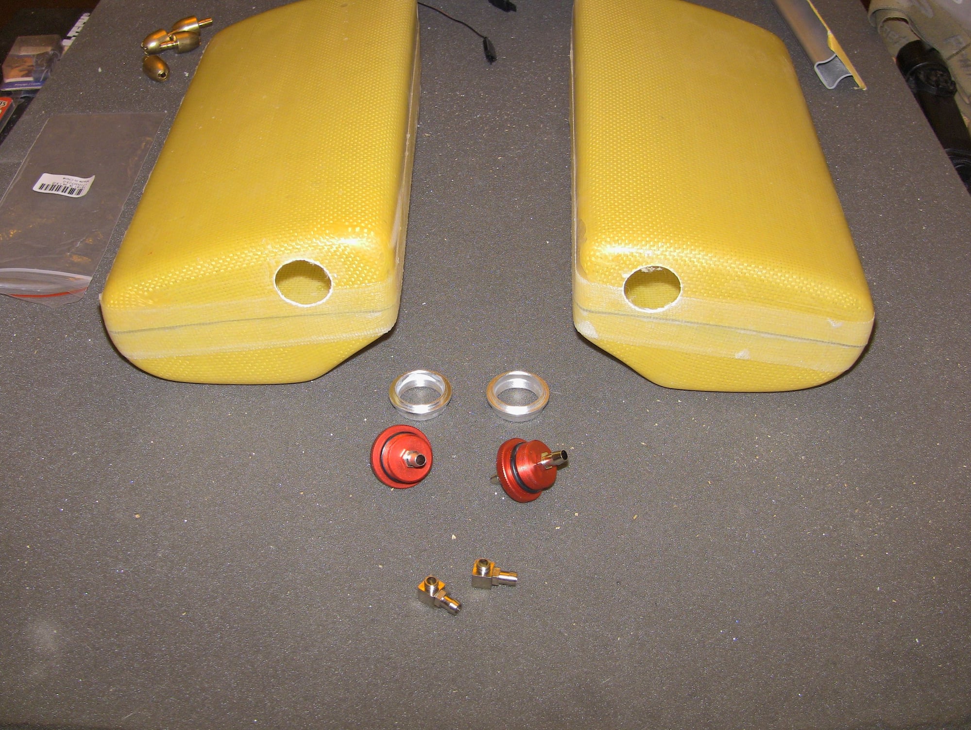
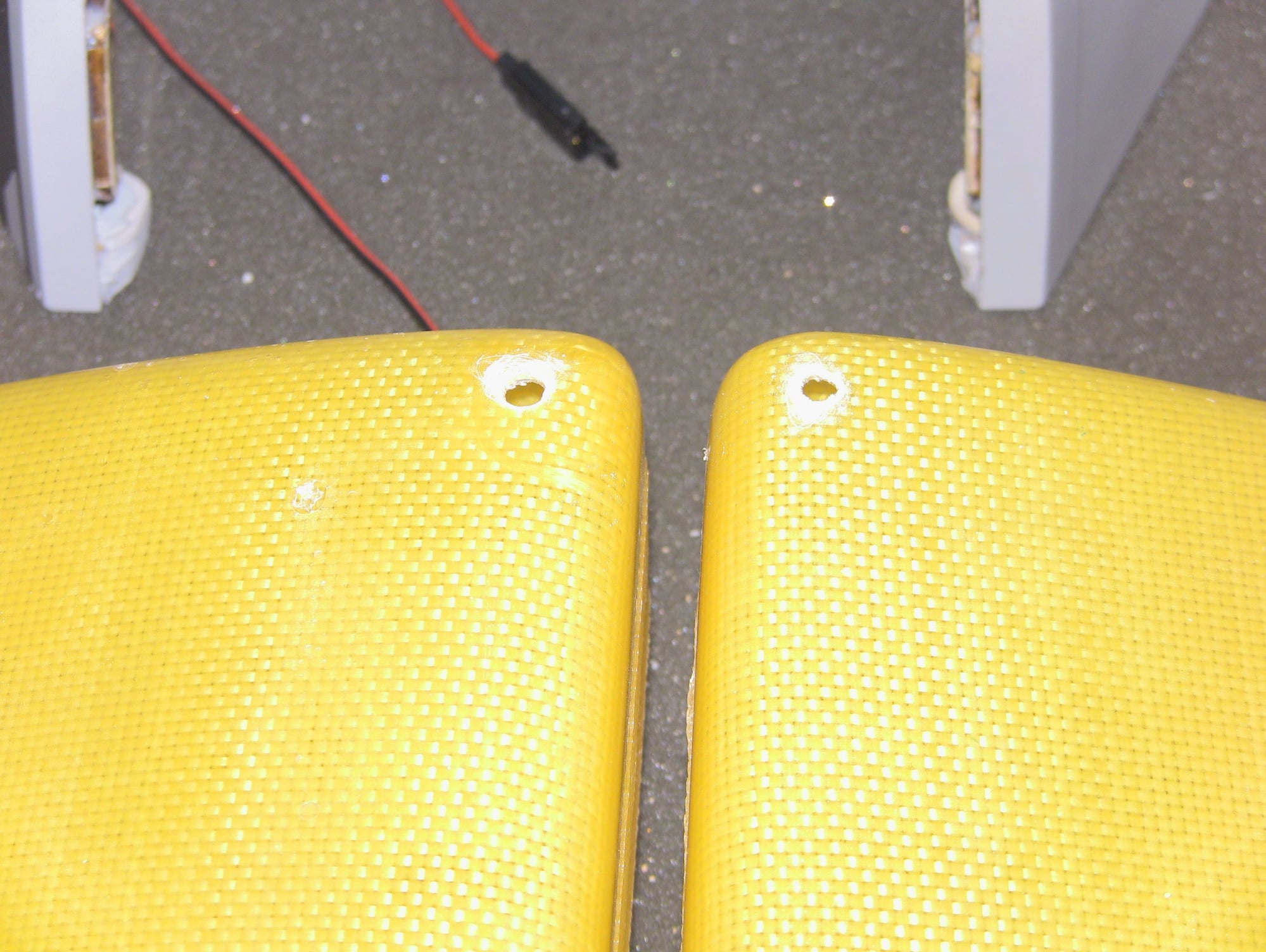
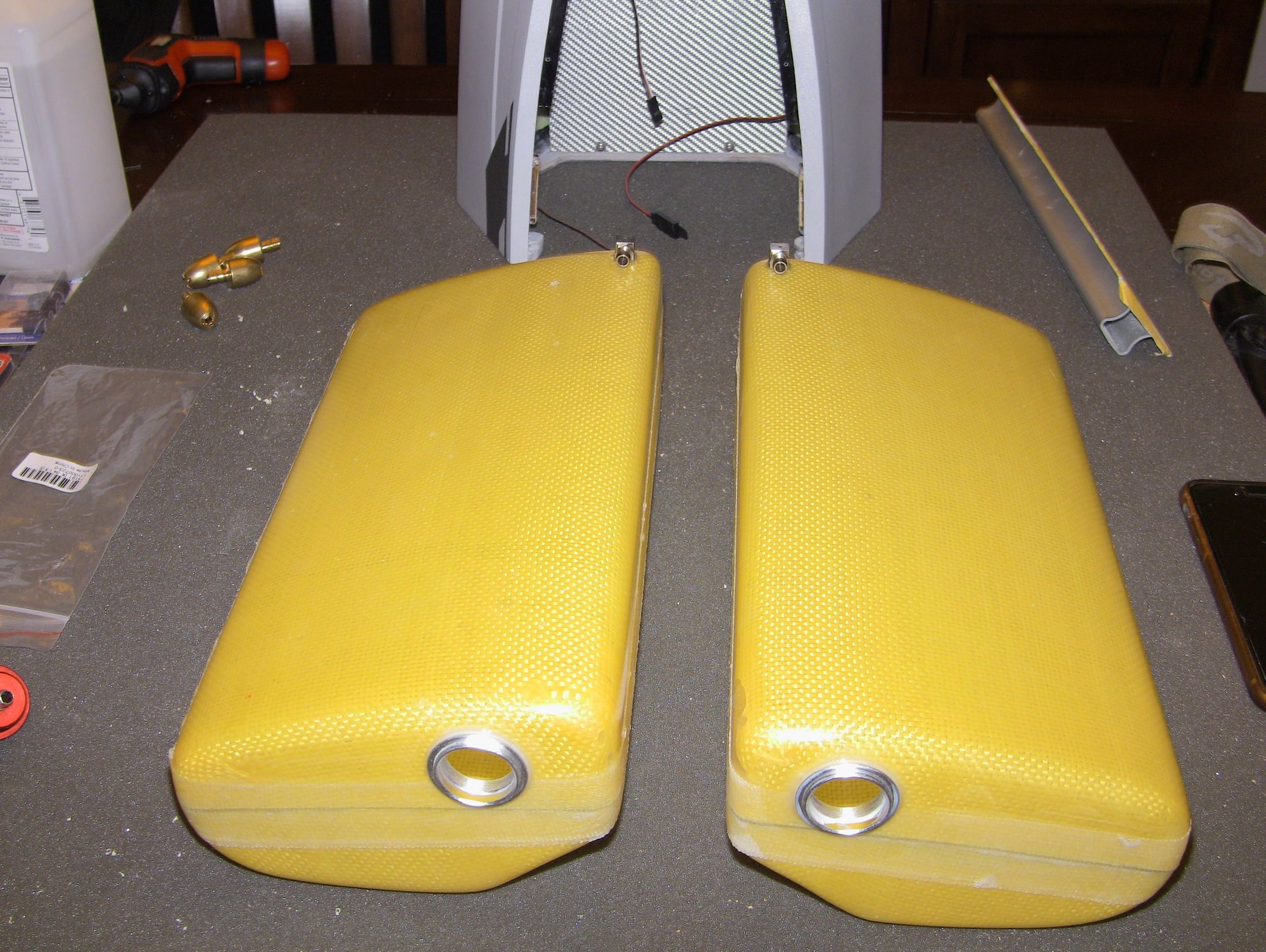
Thread Starter
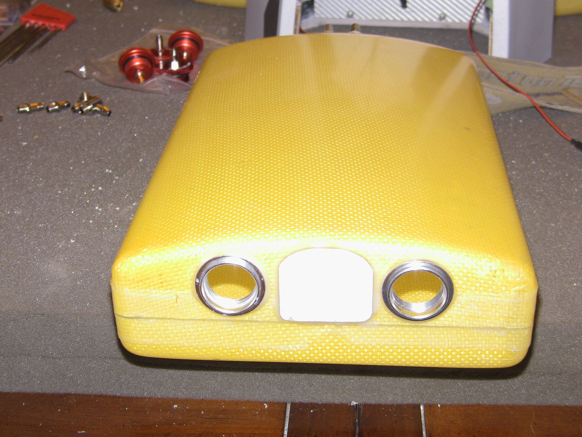
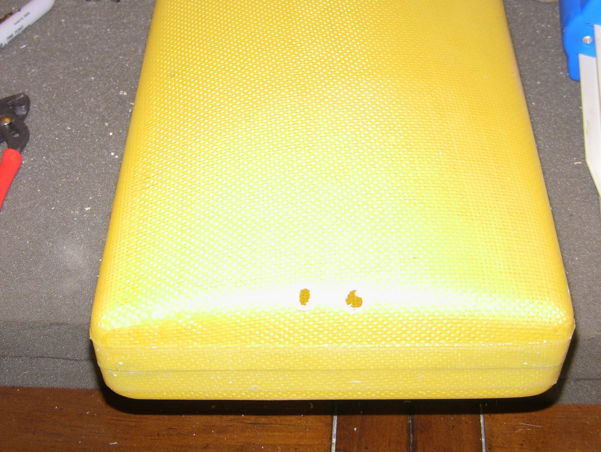
Worked on the fuel tanks tonight, I went ahead and plugged the stock hole on the main tank. With a twin you need two pick ups, I would not feel comfortable using a T and I have no idea where to get one large enough.. The two saddles will be the main tanks and the center tank will feed in the saddle tanks. I was looking for a place to add the two vents which are for the taxi tank as well, still havent found a good spot yet, but once the tanks are done its one to the equipment, the fun stuff!!! The canopy lock is in I just need to glue in the brass tube on the canopy side for the pin. Cheers