


Skymaster F-14 Jolly Roger

 08-07-2021, 08:15 AM
#52

Thread Starter
08-07-2021, 08:19 AM
#53

The following users liked this post:
Ken Mikrut (08-07-2021)
The following users liked this post:
Ken Mikrut (08-08-2021)
08-07-2021, 08:26 AM
#55
Thread Starter
Got some nice progress this week. Fuel system is done, I followed the original design and tested it, looks OK. I finally attached the nose section to the main fuselage.
Now, the retracts issue. I installed and connected all the air valves, sequencer, air tanks, and did the set up.
Nose gear works fine, very smooth movement up and down. Doors are fine. No leaks in any part of the system.
The main gear are different and frustrating issue.
Going up, they hang up at the last 1" or so. Attaching a screen shot from FenderBean's video, it's exactly the same. How did you solve it Keith?
Going down, they slam pretty hard, even though I'm using the throttle function in the Jetronics valves. They build pressure slowly, but the max pressure comes when the gear is already down. Any advice here?
Worst of all, i have 4 SM air tanks. One is for the brakes and speed brake, 3 for the retracts and doors. Pumping 100 PSI, gives one cycle of up-down gear, consuming 25 PSI. Another cycle is not possible.
Maybe I should go electric? Don't know....
Dror.
Last edited by drorso; 08-07-2021 at 08:30 AM.
 08-07-2021, 09:03 AM
#57
Got some nice progress this week. Fuel system is done, I followed the original design and tested it, looks OK. I finally attached the nose section to the main fuselage.
Now, the retracts issue. I installed and connected all the air valves, sequencer, air tanks, and did the set up.
Nose gear works fine, very smooth movement up and down. Doors are fine. No leaks in any part of the system.
The main gear are different and frustrating issue.
Going up, they hang up at the last 1" or so. Attaching a screen shot from FenderBean's video, it's exactly the same. How did you solve it Keith?
Going down, they slam pretty hard, even though I'm using the throttle function in the Jetronics valves. They build pressure slowly, but the max pressure comes when the gear is already down. Any advice here?
Worst of all, i have 4 SM air tanks. One is for the brakes and speed brake, 3 for the retracts and doors. Pumping 100 PSI, gives one cycle of up-down gear, consuming 25 PSI. Another cycle is not possible.
Maybe I should go electric? Don't know....
Dror.
Now, the retracts issue. I installed and connected all the air valves, sequencer, air tanks, and did the set up.
Nose gear works fine, very smooth movement up and down. Doors are fine. No leaks in any part of the system.
The main gear are different and frustrating issue.
Going up, they hang up at the last 1" or so. Attaching a screen shot from FenderBean's video, it's exactly the same. How did you solve it Keith?
Going down, they slam pretty hard, even though I'm using the throttle function in the Jetronics valves. They build pressure slowly, but the max pressure comes when the gear is already down. Any advice here?
Worst of all, i have 4 SM air tanks. One is for the brakes and speed brake, 3 for the retracts and doors. Pumping 100 PSI, gives one cycle of up-down gear, consuming 25 PSI. Another cycle is not possible.
Maybe I should go electric? Don't know....
Dror.
in terms of a solution, I�d start first with lubing and working it in manually with your hand. Just do like 30 to 40 from almost down n locked to all the way up, focusing on that last 90 degree rotation part. If you find it�s still not good enough, my builder ended up removing the gear and disassembling the struts. He then went and dremeled away any parts where he thought he saw some paint over spray...that may cause friction for the rotation..
Air tanks....we added a few large tanks for the retracts system exclusively....so my wheel brakes, speed brakes, and canopy run on a separate system from the retracts. Also we added A LOT of air capacity to the retracts component as it�s pretty air thirsty and requires a lot of volume. I can get 4 or 5 cycles per charge, again at 110 psi
For the hard and aggressive down cycle, we installed restrictors to reduce that. We also adjusted the length of the throw on the down lock actuator....Be aware that those plastics turn buckles can snap on you. We broke a few until the throw was optimized. Test-test-test....he probably did 100 swings before I picked up the jet
if you haven�t already and want some details on how mine was all assembled, check out the detailed assembly thread on our Canadian thread....just google SM F-14 and you�ll probably come across it. Don�t want to violate the posting rules here
Hope this helps
08-07-2021, 09:23 AM
#58
Thread Starter
Ok so with the main retracts, sounds like the challenge at the end of the up cycle is pretty typical. Mine was the same....we just kept lubing it and working it manually with our hands....Even at my last event when ground testing them at 110psi, the one in particular was hanging and lagging. I had serious doubt prior to the maiden that the gear would retract properly....but I�m happy to say they�ve been working great. To be honest, as long as you can get 90% of it up, then the doors seem to help finish the very last part
in terms of a solution, I�d start first with lubing and working it in manually with your hand. Just do like 30 to 40 from almost down n locked to all the way up, focusing on that last 90 degree rotation part. If you find it�s still not good enough, my builder ended up removing the gear and disassembling the struts. He then went and dremeled away any parts where he thought he saw some paint over spray...that may cause friction for the rotation..
Air tanks....we added a few large tanks for the retracts system exclusively....so my wheel brakes, speed brakes, and canopy run on a separate system from the retracts. Also we added A LOT of air capacity to the retracts component as it�s pretty air thirsty and requires a lot of volume. I can get 4 or 5 cycles per charge, again at 110 psi
For the hard and aggressive down cycle, we installed restrictors to reduce that. We also adjusted the length of the throw on the down lock actuator....Be aware that those plastics turn buckles can snap on you. We broke a few until the throw was optimized. Test-test-test....he probably did 100 swings before I picked up the jet
if you haven�t already and want some details on how mine was all assembled, check out the detailed assembly thread on our Canadian thread....just google SM F-14 and you�ll probably come across it. Don�t want to violate the posting rules here
Hope this helps
Also, i'll do a lot of manual up and down, hope it will help. I guess I'll add another air tank, I got a Robart big tank.
Thank you very much for your help.
Dror.
08-08-2021, 07:07 AM
#60
Also consider pushing the struts in and out by putting the plane on his legs and pushing on its back a little. These struts get lubed by compressing and become way more smooth after a few pumps.
Mechanically, though, there's no force at all from the pistons to push them all the way up, and only inertia gets them closed, so they need to go up fast.
Mechanically, though, there's no force at all from the pistons to push them all the way up, and only inertia gets them closed, so they need to go up fast.
The following users liked this post:
Ken Mikrut (08-08-2021)
08-08-2021, 08:00 AM
#61

So on the mains, I put a 9 second pulse pressure build on the down stroke and full no delay pressure on the up. Thats why I used the jettronic valves because they have this ability, the main gear will not rotate all that well if you dont stroke the gear. This is what lubricates the internal shaft that rotates as the mains go up into the fuse. Its also very important to not over pressurize the strut on the mains this will prevent them from rotating and going all the way up no matter what pressure you use. I feel my system to 100-105 PSI and they go up just fine since the main struts are collapsed a bit when its on the ground. This allows the strut seal to keep lubrication and as it lifts off it extends and then rotates nicely. You need the gear to just fall out of the bay to avoid breaking the small lock cylinder on the strut and give it full pressure on the up.
My doors are on two different valves, the back mains on one and the rest including the nose on the other.
The above pitch was before EDFJim mentioned I needed to stroke the gear to lube the seal ring, after that they started going all the way up no issue.
My doors are on two different valves, the back mains on one and the rest including the nose on the other.
The above pitch was before EDFJim mentioned I needed to stroke the gear to lube the seal ring, after that they started going all the way up no issue.
Last edited by FenderBean; 08-08-2021 at 08:03 AM.

The following users liked this post:
Ken Mikrut (08-08-2021)
09-27-2021, 07:48 AM
#62
Thread Starter
Hi guys, turbines installation question:
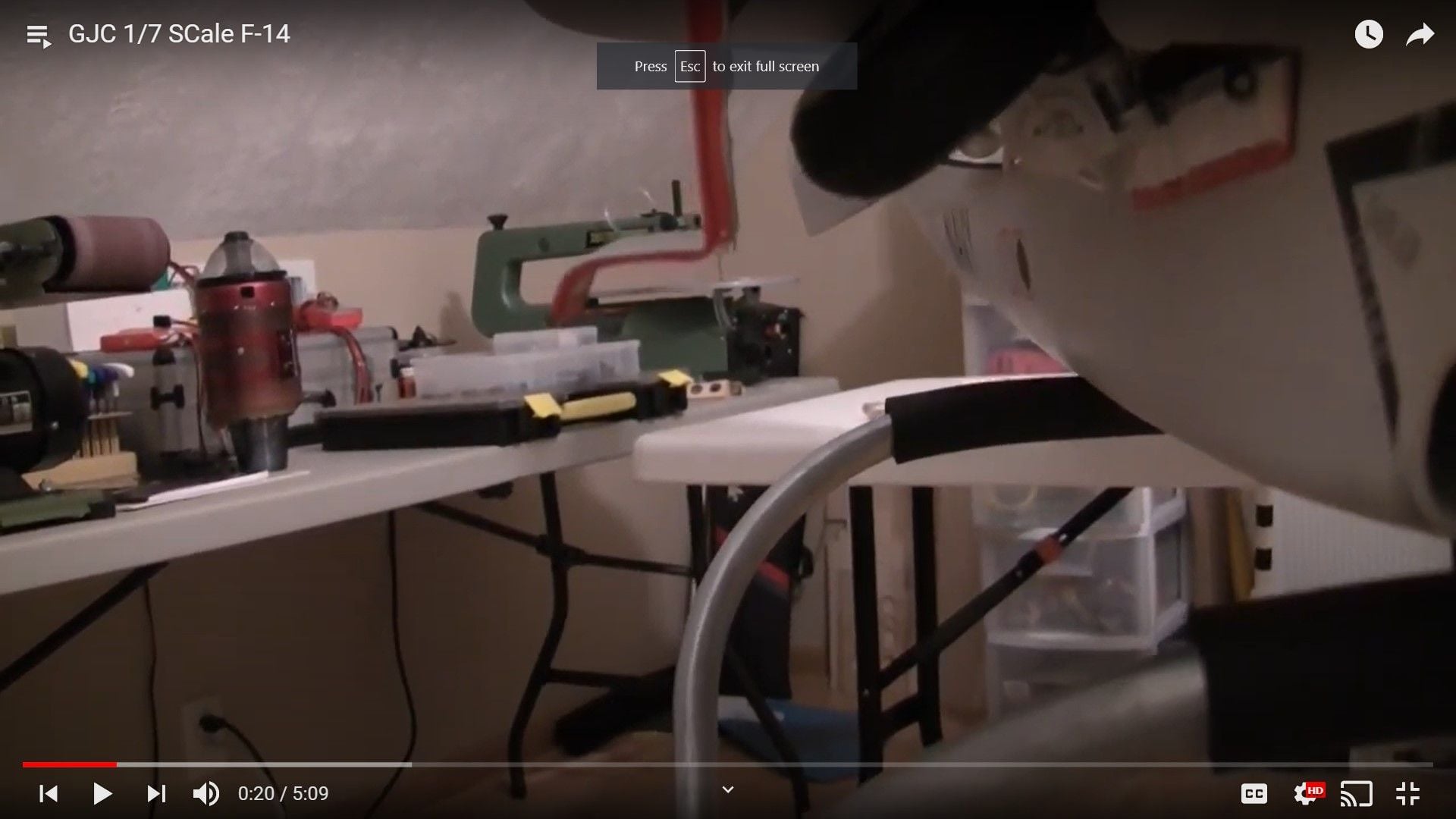
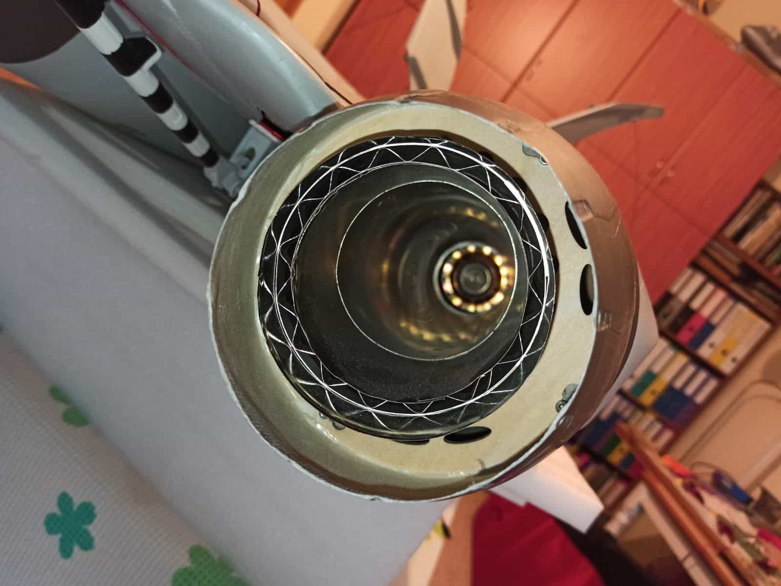
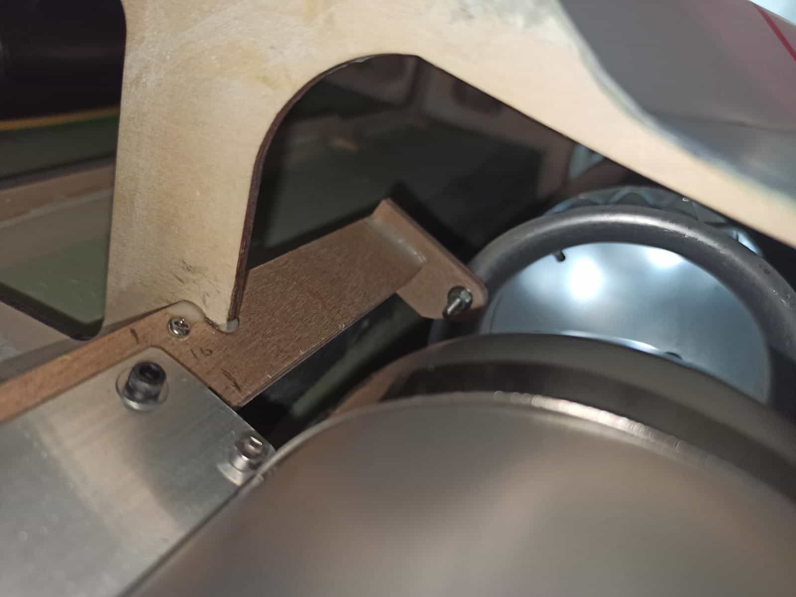
The two Merlins 166 are installed, as well as the tail pipes. The tail pipes end about 1.5" (4 cm) inside the tail cones. I guess this is the design, as there is not much room for changes.
Question is, if this will not burn the tail cones. In all my other jets, the tail pipe ends a little bit after the tail cone.
See the pictures.
09-27-2021, 07:52 AM
#63
Mine are pretty near flush with the back of the tail cones...I didn�t build mine so can�t offer a lot of help or guidance....but I wouldn�t leave your pipes that far recessed into the jet if it was me
09-27-2021, 08:01 AM
#64
I have the same motors in mine and my tailpipes actually touch the tail cone and stick out on one side about 3mms I did add some ceramic paint to the tailcones but being a dual walled pipe and at the very tip its not hot enough to do anything.
When I removed the KTs and added the 166 I had to rebuild up the rails form having to butcher them for the 170s.
Even with the motors as far forward as possible for CG the tail pipes and gap made the pipes as they are now. Not sure how you have pipes that can be pulled in that far unless they made them too short.
Last edited by FenderBean; 09-27-2021 at 08:03 AM.
09-27-2021, 08:22 AM
#65
Thread Starter
I have the same motors in mine and my tailpipes actually touch the tail cone and stick out on one side about 3mms I did add some ceramic paint to the tailcones but being a dual walled pipe and at the very tip its not hot enough to do anything.
When I removed the KTs and added the 166 I had to rebuild up the rails form having to butcher them for the 170s.
Even with the motors as far forward as possible for CG the tail pipes and gap made the pipes as they are now. Not sure how you have pipes that can be pulled in that far unless they made them too short.
When I removed the KTs and added the 166 I had to rebuild up the rails form having to butcher them for the 170s.
Even with the motors as far forward as possible for CG the tail pipes and gap made the pipes as they are now. Not sure how you have pipes that can be pulled in that far unless they made them too short.
The pipes bellmouth are connected to the ears on the turbines rails, that's a given fact. Can't play with this one.
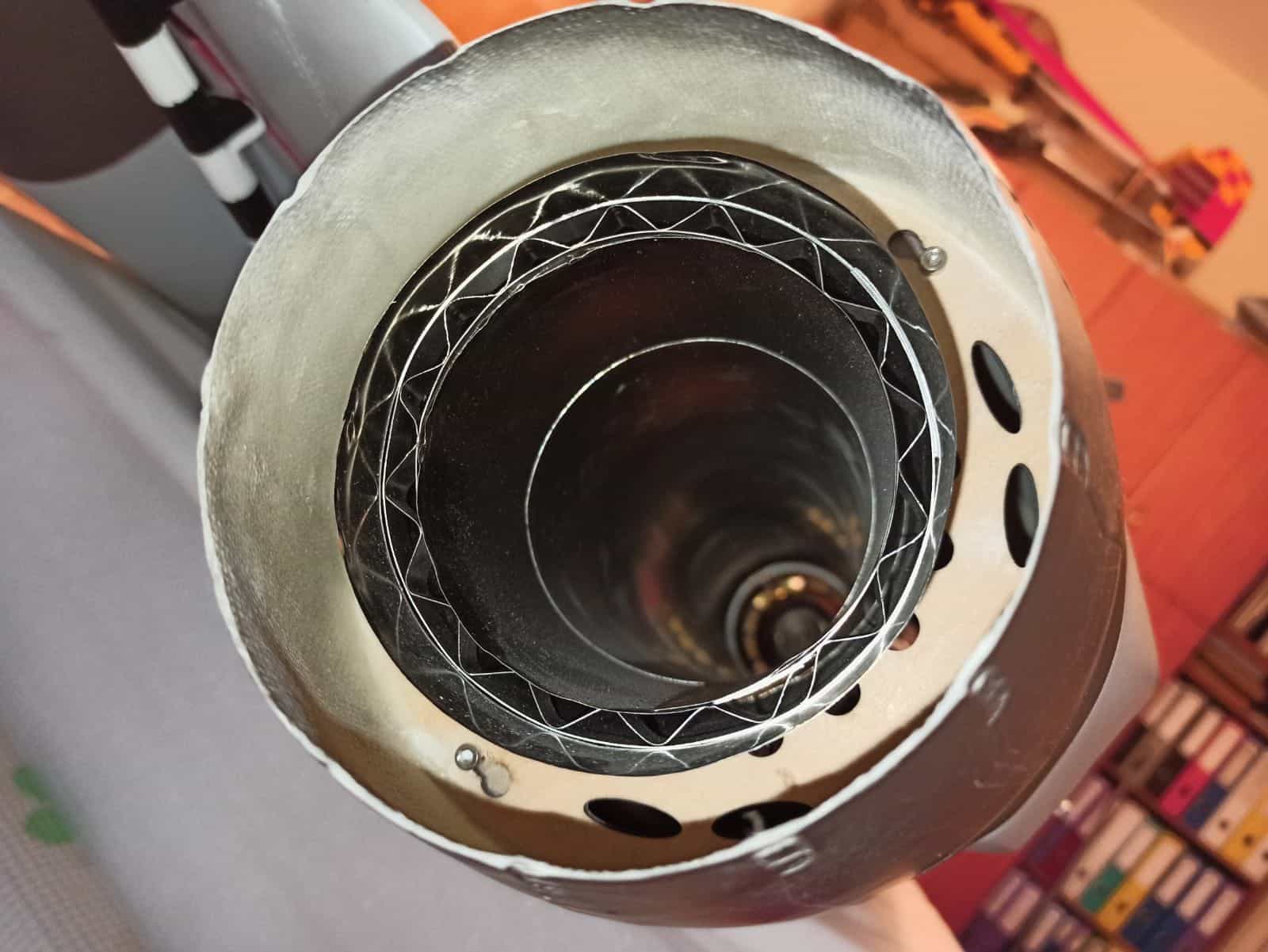
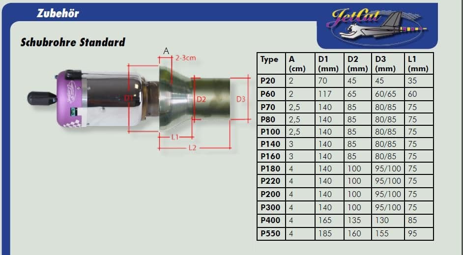
I pushed the turbines as backwards as I can to keep the 2.5-3 cm gap between the turbine and the tail pipe (per the drawing attached).
After all this, the tail pipes are short about 1.5" to be flushed with the tail cones.
I'll check with skymaster.
If it's not to complicated, can someone measure the tail pipe overall length? Might be that mine are shorter?
 09-27-2021, 09:15 AM
#66

My Feedback: (6)
That�s a jet-cat in your pic ..
Anyways , the gap of 2-3cm is measured between the end of the turbine exhaust cone and the lip at the beginning of the tailpipe , disregard the bell mouth ..
u can�t leave the tailpipe as shown on your pic , it�s wayyy too far in , although on standard running mode you might get away with it without damage to the FG tail cone but that depends on the airflow in there , however there are high chances that it might catch on fire on a hot start situation or on a fast acceleration with smoke on situation �
09-28-2021, 08:56 AM
#67
Thread Starter
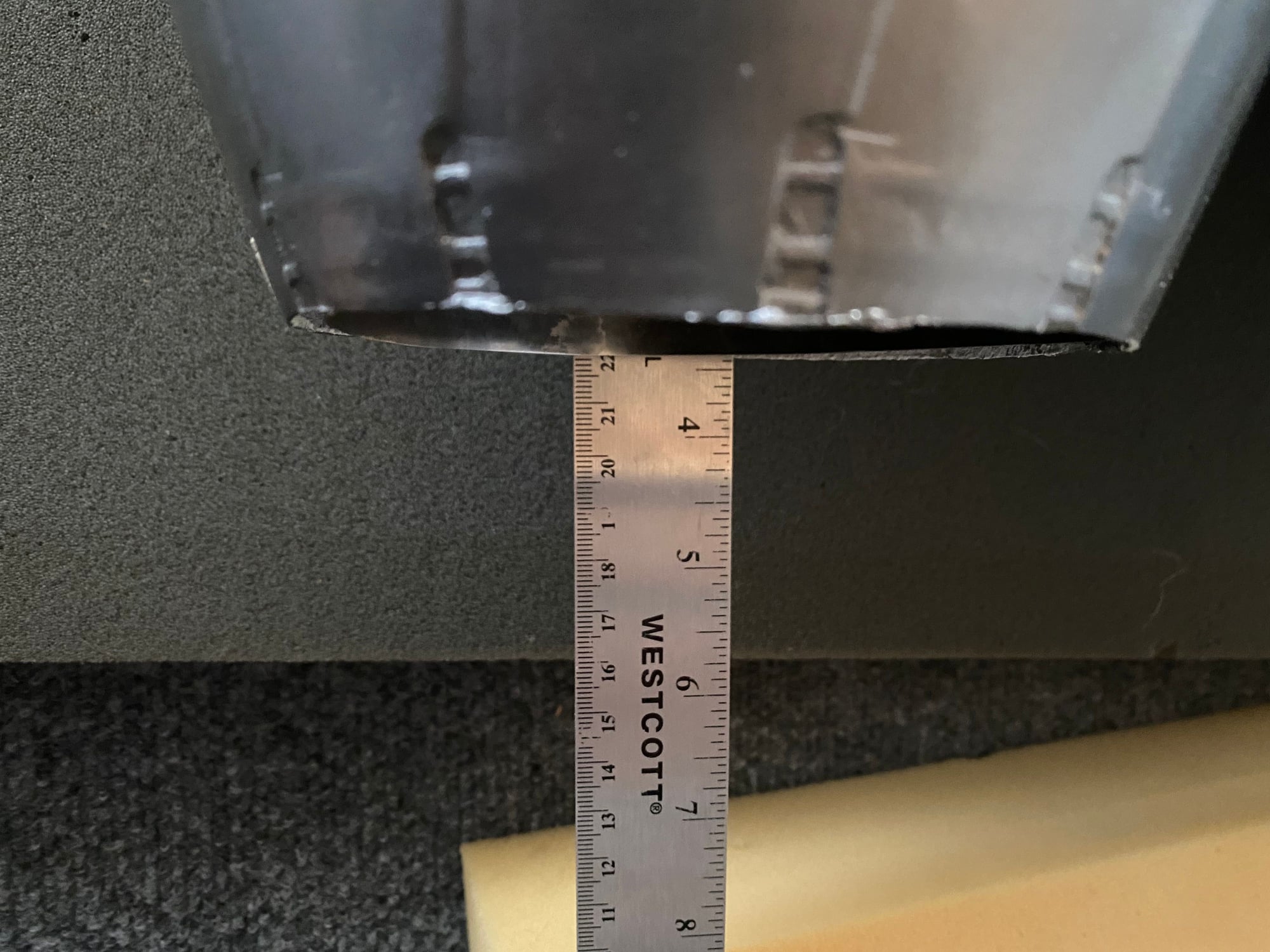
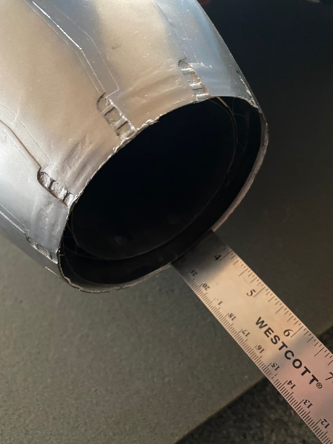
Some pictures to show the issue:
The schema is showing the distance between the tail pipe front mount and the fuselage end is 20". The tail cone is another 3.5". Total is 23.5".
The tail pipe is 22", leaving a gap of 1.5".
I'll appreciate it if someone can measure these distances in his plane, maybe I'll figure out what I'm doing wrong, or if there is a problem with my kit/tail pipe.
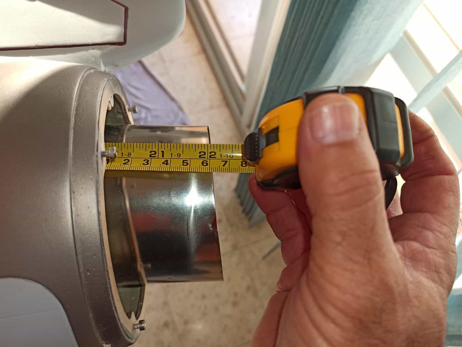
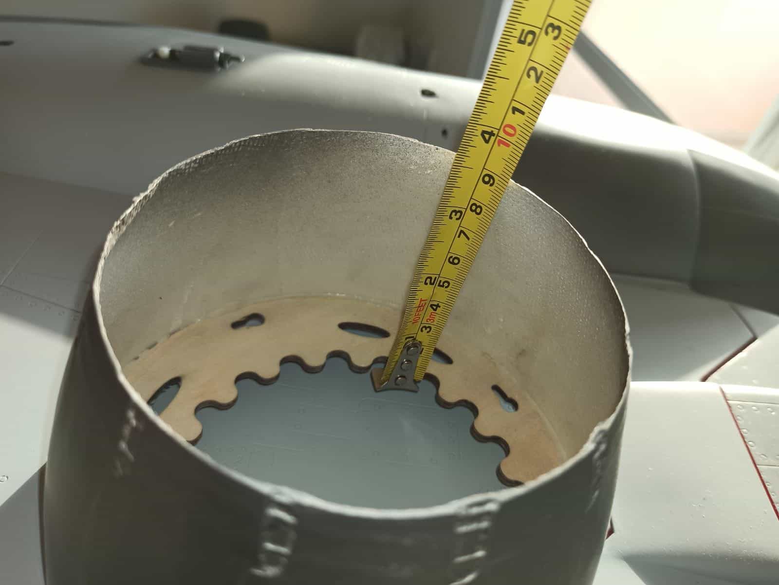
09-28-2021, 09:27 AM
#68
If the rails are correct length then your pipes are too short, I have my bellmouth on the front side of the bolt so wind pushes it against the wood mount of the bolt. So either the rails are the wrong length or the pipe is.
With the end of the pipe angled out my pipe touches the outer side of the nozzle and the and joint is past the pipe wood ring on the nozzle. Based on the second picture with the pipe sticking out the back with the nozzle off it needs to be longer on the bellmouth side or the the rails needs to be longer. this will also move the motor back to maintain pipe gap.
With the end of the pipe angled out my pipe touches the outer side of the nozzle and the and joint is past the pipe wood ring on the nozzle. Based on the second picture with the pipe sticking out the back with the nozzle off it needs to be longer on the bellmouth side or the the rails needs to be longer. this will also move the motor back to maintain pipe gap.
Last edited by FenderBean; 09-28-2021 at 09:30 AM.
09-29-2021, 10:35 AM
#69
Thread Starter
I got a reply from Skymaster, pretty strange. "the screw mounting in front of pipe is not needed. the pipe is supported from rear side of fuselage".
Keith, as you are using same turbines, can you do me a favor and measure the distance from the tail pipe mount to the end of the tail cone, and the length of the tail pipes?
It seems that I'll have to manage on my own and extend the tail pipes somehow. This project is a real pain...
Keith, as you are using same turbines, can you do me a favor and measure the distance from the tail pipe mount to the end of the tail cone, and the length of the tail pipes?
It seems that I'll have to manage on my own and extend the tail pipes somehow. This project is a real pain...
09-30-2021, 07:35 AM
#70
I got a reply from Skymaster, pretty strange. "the screw mounting in front of pipe is not needed. the pipe is supported from rear side of fuselage".
Keith, as you are using same turbines, can you do me a favor and measure the distance from the tail pipe mount to the end of the tail cone, and the length of the tail pipes?
It seems that I'll have to manage on my own and extend the tail pipes somehow. This project is a real pain...
Keith, as you are using same turbines, can you do me a favor and measure the distance from the tail pipe mount to the end of the tail cone, and the length of the tail pipes?
It seems that I'll have to manage on my own and extend the tail pipes somehow. This project is a real pain...

 10-15-2021, 07:27 PM
#72
Thread Starter
Thanks Keith, that might explain the difference. It seems that you pushed back the turbines just to the right place to fit the pipes.
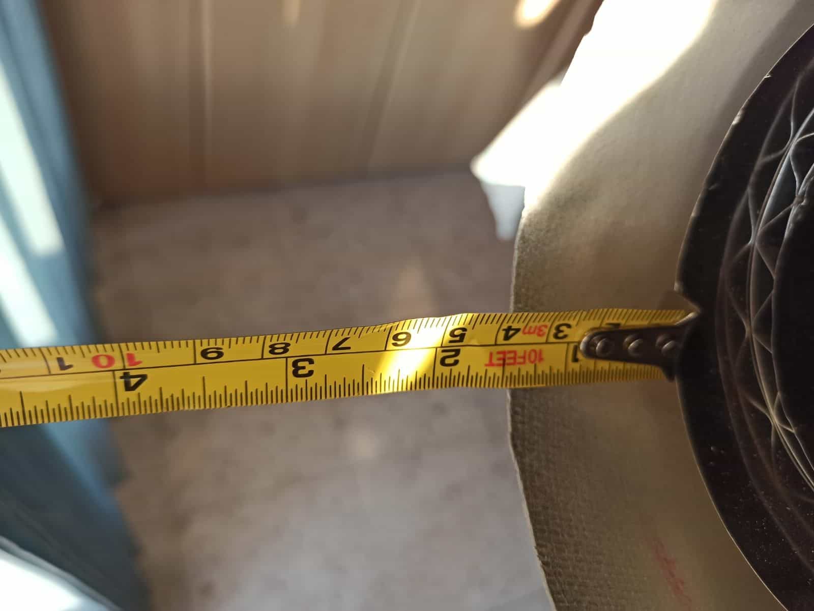
Can you please measure the distance as shown in the picture? that will help to decide what next.
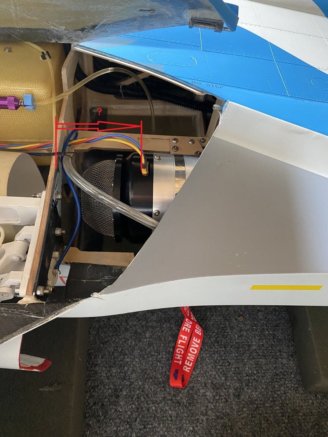
Distance between the bulkhead and the plug
Can you please measure the distance as shown in the picture? that will help to decide what next.
Distance between the bulkhead and the plug
10-16-2021, 07:03 AM
#73
77mm is what I have, this is a position, it will all the radio equipment to be positioned better. I had everything crammed in the nose to help with CG with the old motors, when I put the 166 in I lost what little nose weight I had. Unfortunately my wing control burned up at KY this year so I now have linear actuators that plug into the power system directly so I can ditch the 11.1 Ion. This will require I add some weight to the nose again.
10-16-2021, 08:09 AM
#74
Thread Starter
Thanks again Keith, now it makes sense. In my F-14 this distance is 40 mm. I guess you had to extend the engines rails with the tail pipes mounts.
Anyway, I will just add some stainless steel extension to the pipes, I prefer this solution rather than moving the engines backwards.
Thanks again, will update as soon as I get the extensions.
Anyway, I will just add some stainless steel extension to the pipes, I prefer this solution rather than moving the engines backwards.
Thanks again, will update as soon as I get the extensions.