


F-16XL ARF by Global Knight Models from Global Jet Club
 07-13-2021, 02:10 PM
#301

Thread Starter
My Feedback: (20)
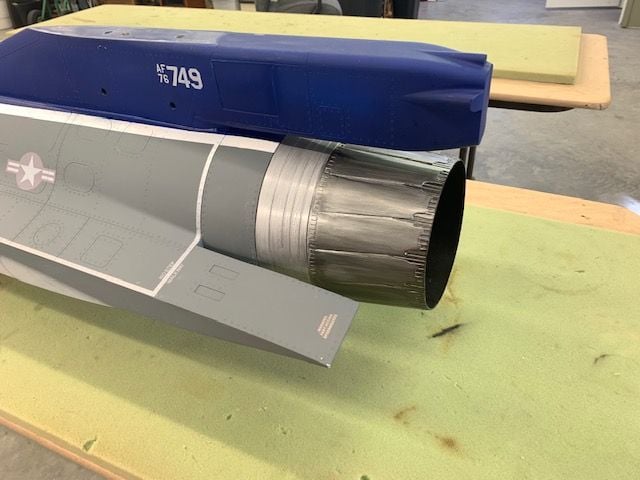
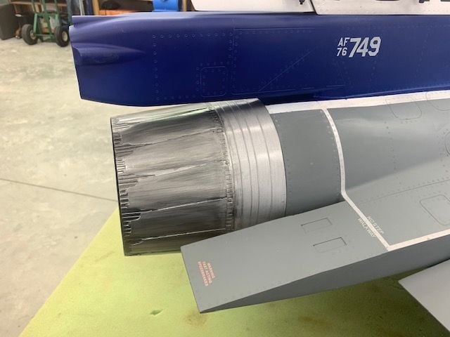
Redecorating AB nozzle.
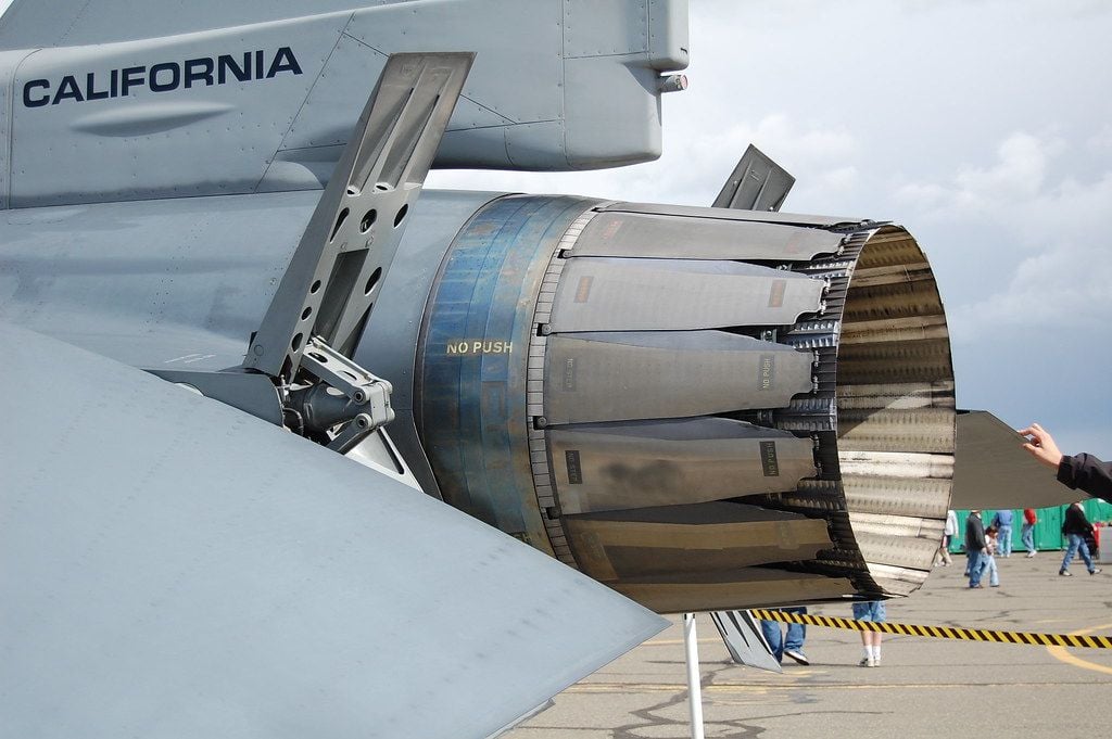
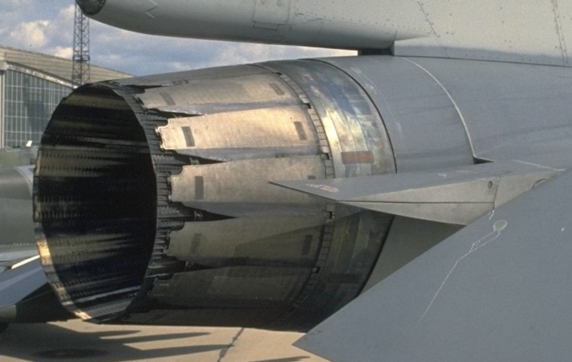
Found a couple of photos of the Pratt Whitney F-100 AB nozzle and decided to try and redecorate my nozzle to look a little more like the full scale. I studied up on some nozzle weathering techniques on YouTube using a paint wash.
I plan to do this cheap and easy using on hand supplies and minimum work with a brush. I found some aluminum color KlassKote epoxy paint in the paint cabinet and will use it as a base coat.
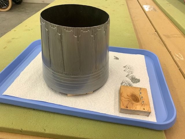
Epoxy paint base coat applied with a brush. I made the brush strokes parallel with the burner can rings on the leading edge and parallel to the nozzle turkey feathers on the trailing edge. Hopefully that will compliment my decorating plan. The mounting screw heads for the air data probe were painted to match the air data probe color.
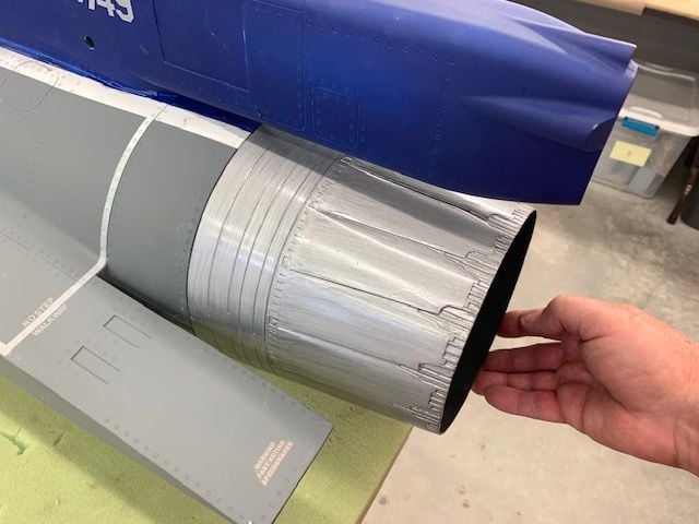
Test look after it was dry to the touch. After the paint cures I will lightly wet sand with 1200 grit to take off the gloss and do some art work. I've never done anything like this before so it will be a learning experience.
Found a couple of photos of the Pratt Whitney F-100 AB nozzle and decided to try and redecorate my nozzle to look a little more like the full scale. I studied up on some nozzle weathering techniques on YouTube using a paint wash.
I plan to do this cheap and easy using on hand supplies and minimum work with a brush. I found some aluminum color KlassKote epoxy paint in the paint cabinet and will use it as a base coat.
Epoxy paint base coat applied with a brush. I made the brush strokes parallel with the burner can rings on the leading edge and parallel to the nozzle turkey feathers on the trailing edge. Hopefully that will compliment my decorating plan. The mounting screw heads for the air data probe were painted to match the air data probe color.
Test look after it was dry to the touch. After the paint cures I will lightly wet sand with 1200 grit to take off the gloss and do some art work. I've never done anything like this before so it will be a learning experience.
Last edited by Viper1GJ; 07-13-2021 at 04:59 PM.
 07-13-2021, 02:58 PM
#302
Thread Starter
My Feedback: (20)
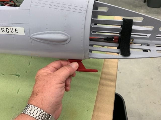
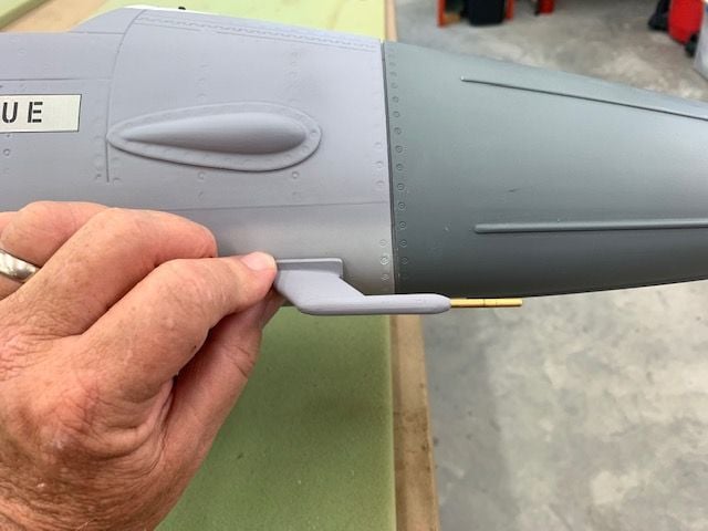
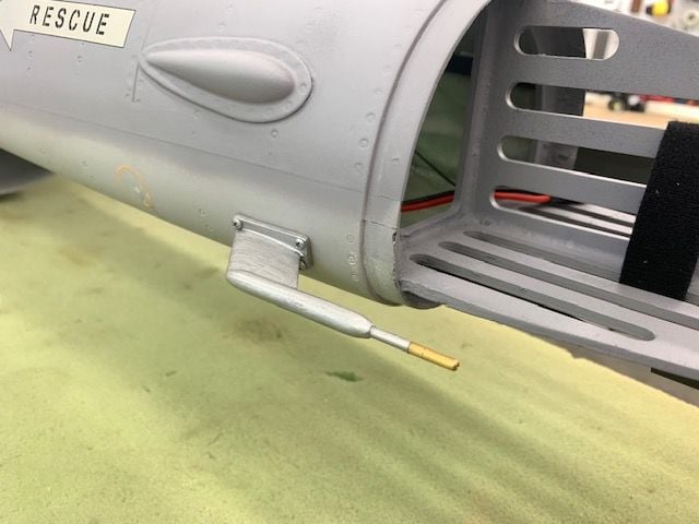
Semi scale F-16 aIr data probe pitot tube
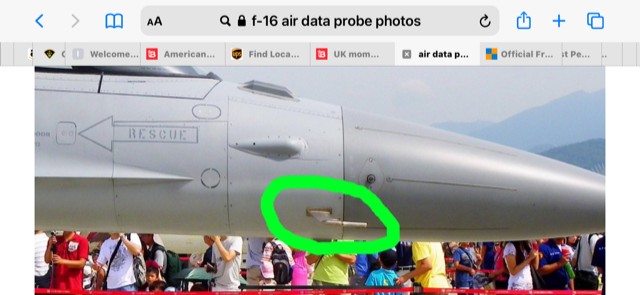
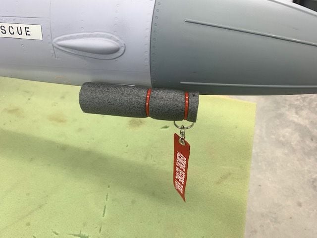
On my last three F-16 models I installed a pitot tube in a semi scale air data probe that hangs on the lower right side of the forward fuse similar to the photo above. It's certainly not necessary but it's fun to play with and listen to. The Jeti Mspeed module was installed back in May before the first flight but I ran out of time to install the pitot tube.
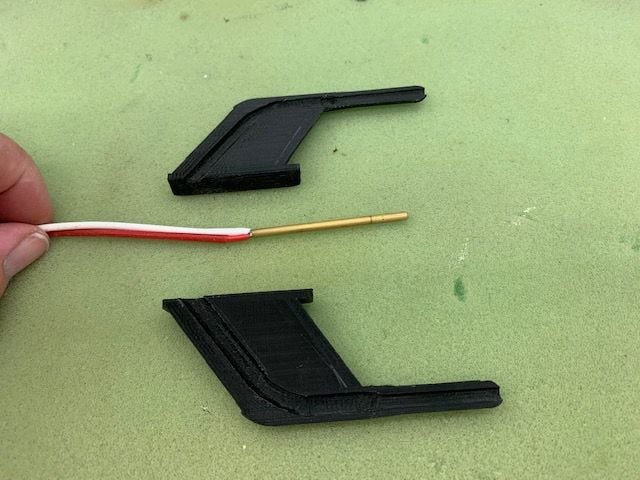
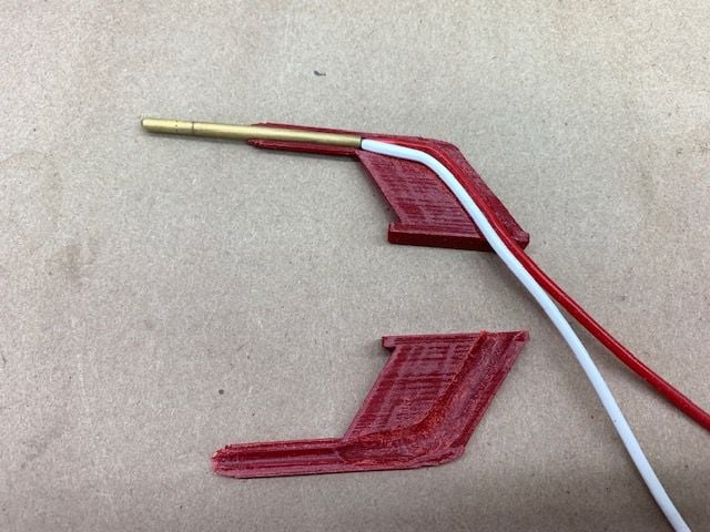
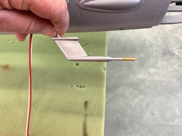
Several years ago a friend of mine 3D printed an F-16 looking air data probe shell to hold a Jeti pitot tube.
It was too big for the XL jet so I ask him for the STL file and modified it.
Since I am CAD illiterate I can't draw one the right size. But I have learned how to modify the size of existing designs using my slicer software by changing the dimensions in proportion. So I took his design and reduced it's size to about 75%. It was as small as I could make it and still stuff the Jeti pitot tube inside.
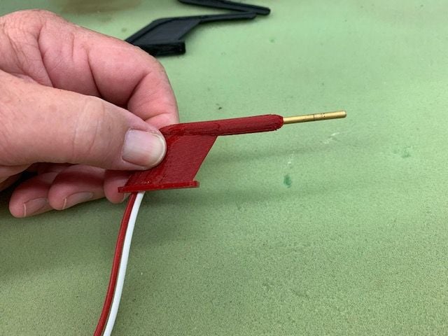
TLAR dry fit for size
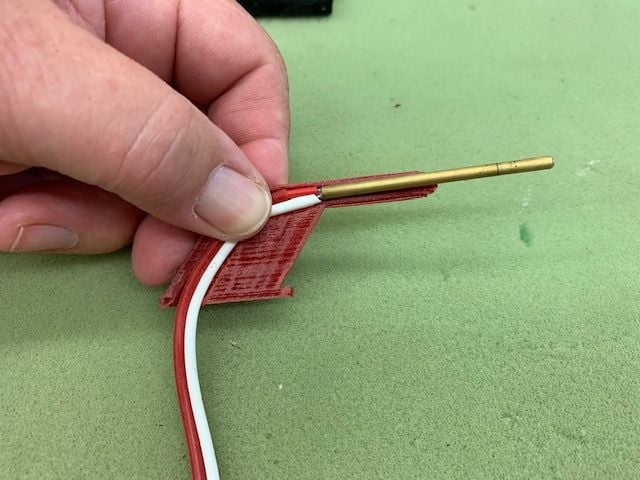
Test fit with tubing
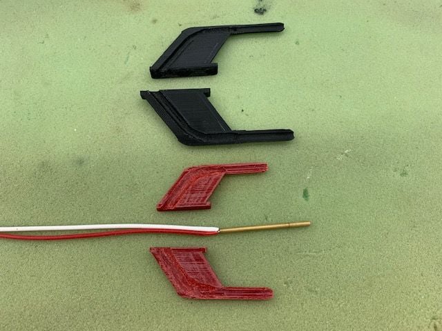
The inside channel needs to be bigger
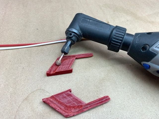
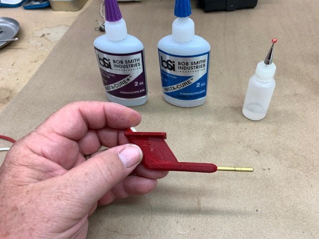
Small Perma Grit ball grinder used to open the channel
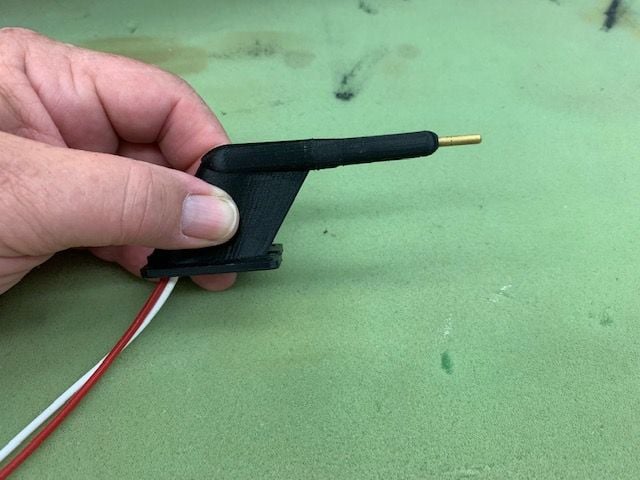
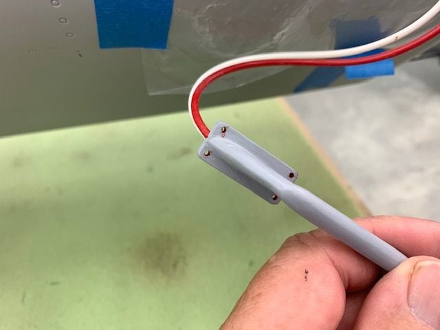
Pitot tube tack glued in with thin CA ready for closing
Air data probe halves glued together with medium CA

Surfaces filled with glazing putty
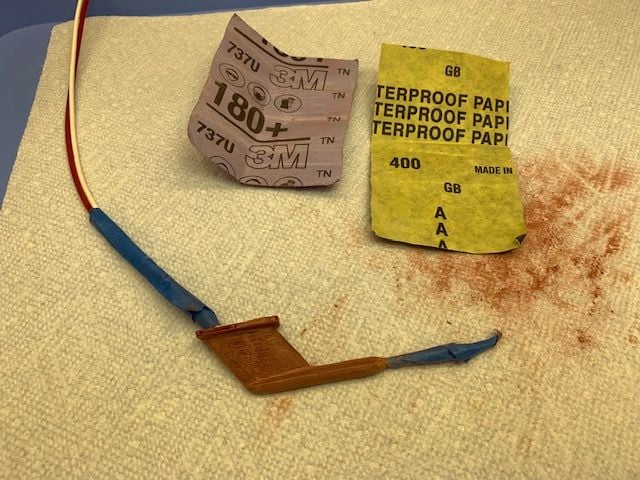
Sanded
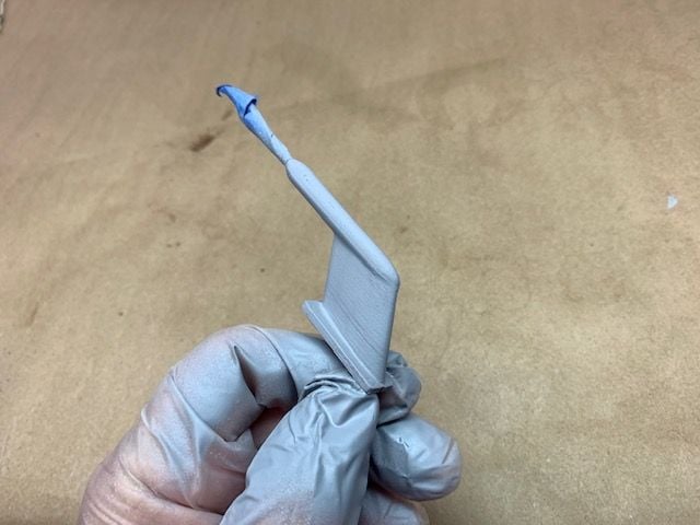
Primer sprayed on and more putty to fill printer lines
On my last three F-16 models I installed a pitot tube in a semi scale air data probe that hangs on the lower right side of the forward fuse similar to the photo above. It's certainly not necessary but it's fun to play with and listen to. The Jeti Mspeed module was installed back in May before the first flight but I ran out of time to install the pitot tube.
Several years ago a friend of mine 3D printed an F-16 looking air data probe shell to hold a Jeti pitot tube.
It was too big for the XL jet so I ask him for the STL file and modified it.
Since I am CAD illiterate I can't draw one the right size. But I have learned how to modify the size of existing designs using my slicer software by changing the dimensions in proportion. So I took his design and reduced it's size to about 75%. It was as small as I could make it and still stuff the Jeti pitot tube inside.
TLAR dry fit for size
Test fit with tubing
The inside channel needs to be bigger
Small Perma Grit ball grinder used to open the channel
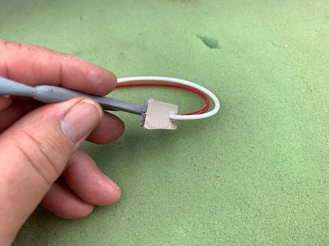
Pitot tube tack glued in with thin CA ready for closing
Air data probe halves glued together with medium CA
Surfaces filled with glazing putty
Sanded
Primer sprayed on and more putty to fill printer lines
07-13-2021, 03:10 PM
#303
Thread Starter
My Feedback: (20)
Pitot tube install continued...
Positioned and hole drilled for air tubes
Flat base needed fitting to curve of fuse side. Plastic taped over area for a release agent.
Mounting holes pre drilled so location can be seen from outside after putty is applied.
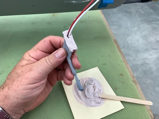
Icing light weight body putty used to fill the base
Air data probe held in place till putty kicked off and cured

Removed ready for trimming while putty is still soft

Excess putty trimmed off before it got hard
Ready for sanding
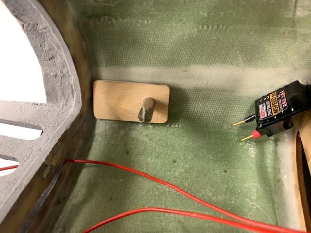
Plywood mounting plate epoxied inside fuse side to hold screws. Screwdriver used to keep holes centered.
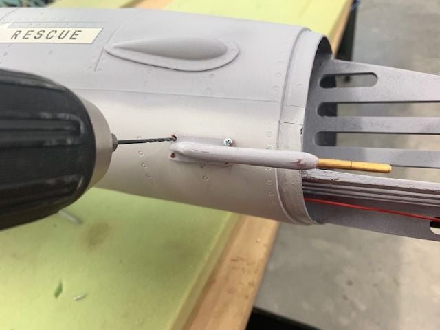
Mounting holes drilled
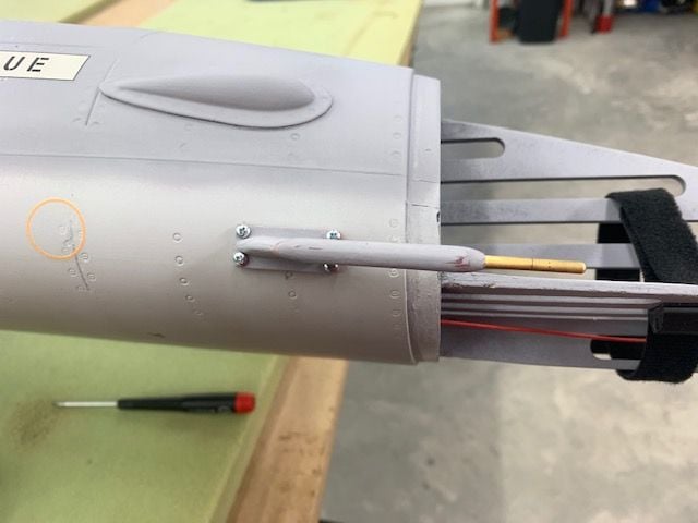
Mounting done.
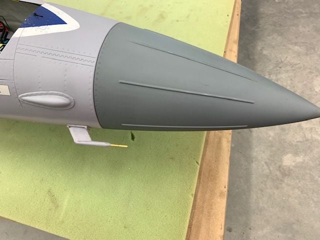
A little bigger than scale but OK for me
Painted with KlassKote aluminum paint and ready for final install and connection to Jeti Mspeed sensor.
Positioned and hole drilled for air tubes
Flat base needed fitting to curve of fuse side. Plastic taped over area for a release agent.
Mounting holes pre drilled so location can be seen from outside after putty is applied.
Icing light weight body putty used to fill the base
Air data probe held in place till putty kicked off and cured
Removed ready for trimming while putty is still soft
Excess putty trimmed off before it got hard
Ready for sanding
Plywood mounting plate epoxied inside fuse side to hold screws. Screwdriver used to keep holes centered.
Mounting holes drilled
Mounting done.
A little bigger than scale but OK for me
Painted with KlassKote aluminum paint and ready for final install and connection to Jeti Mspeed sensor.
07-13-2021, 04:49 PM
#304
Thread Starter
My Feedback: (20)
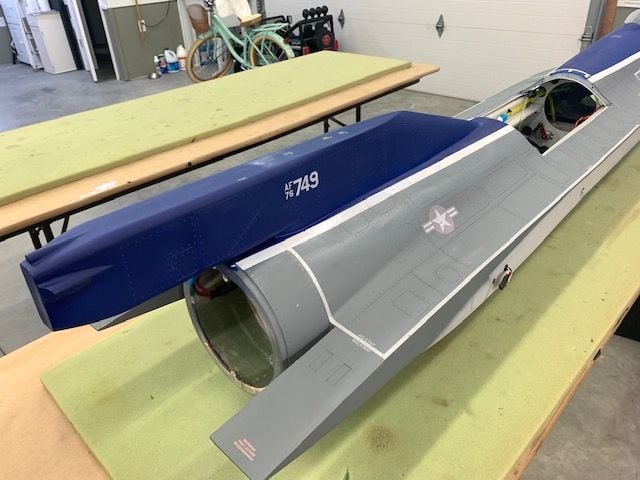
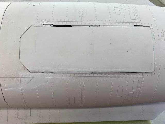
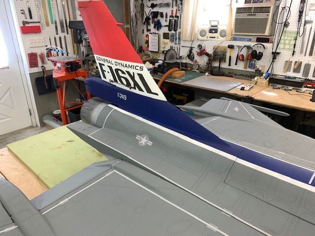
Body work and primer

The plan for repainting the fuse is the same as for the nozzle, cheap, quick, using materials on hand. I rough sanded the epoxy fill in the crack and then applied two rounds of Bondo glazing putty with and artist trowel. Then block sanded with 220 grit.
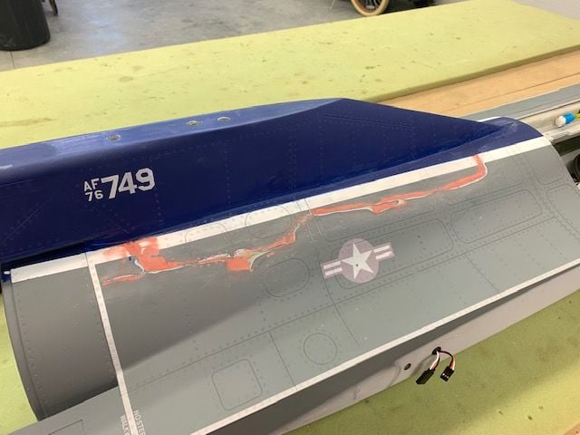
Final putty sanding with 400 grit by hand. It's not perfect but it's good enough for this project. I tried to keep the putty out of the rivet circles as much as possible.
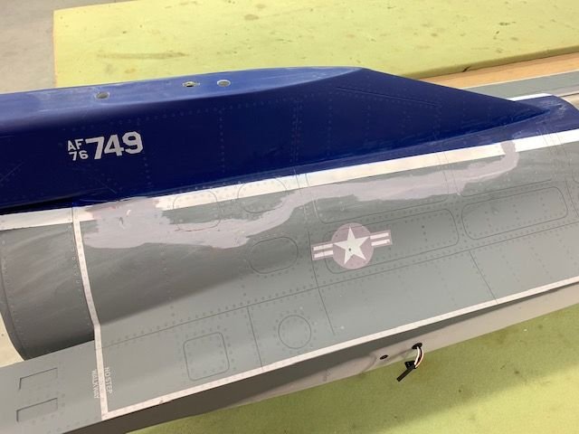
Grey primer from rattle can sprayed into paper plate and then brushed on with fine water color brush and then fine sanded. Panel lines scribed on after primer applied. I not going to worry about the rivet circles since there were not many affected.
White stripe got touched up with some rattle can white I had in the cabinet. It got sprayed on a paper plate and brushed on. It will all get a coat of matt clear when done so the white gloss will be flat in the end. Next is to mask off the white and touch up the grey and blue. I plan to use the airbrush for that if i can figure it out how to make it go again.
The plan for repainting the fuse is the same as for the nozzle, cheap, quick, using materials on hand. I rough sanded the epoxy fill in the crack and then applied two rounds of Bondo glazing putty with and artist trowel. Then block sanded with 220 grit.
Final putty sanding with 400 grit by hand. It's not perfect but it's good enough for this project. I tried to keep the putty out of the rivet circles as much as possible.
Grey primer from rattle can sprayed into paper plate and then brushed on with fine water color brush and then fine sanded. Panel lines scribed on after primer applied. I not going to worry about the rivet circles since there were not many affected.
White stripe got touched up with some rattle can white I had in the cabinet. It got sprayed on a paper plate and brushed on. It will all get a coat of matt clear when done so the white gloss will be flat in the end. Next is to mask off the white and touch up the grey and blue. I plan to use the airbrush for that if i can figure it out how to make it go again.
07-14-2021, 03:25 PM
#305
Thread Starter
My Feedback: (20)
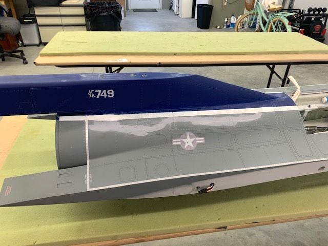
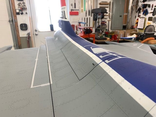
Final paint touch up
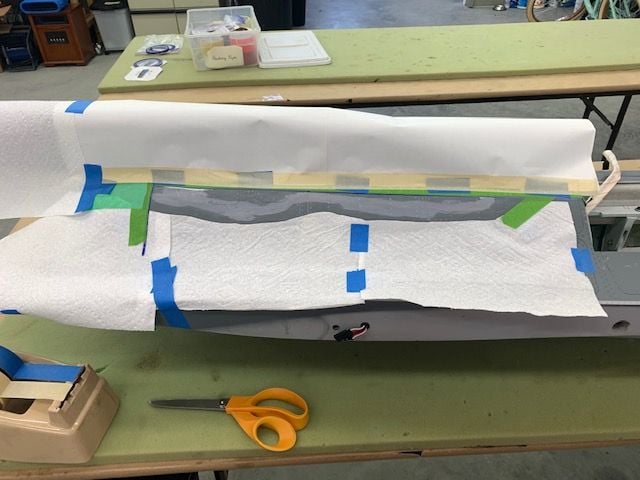
Masking for grey touch up. I spent about 5 mins masking this off and got ready to airbrush. Not so fast. Next I spent about an hour fighting my airbrush and finding out that when I used it to spray the soft lines on the nose back in May some paint got in the trigger slide and it was sticking. Took it all apart and got it cleaned out and started to spray and it quit. Found out paint too thick. Thinned paint and got it done in about 3 min.
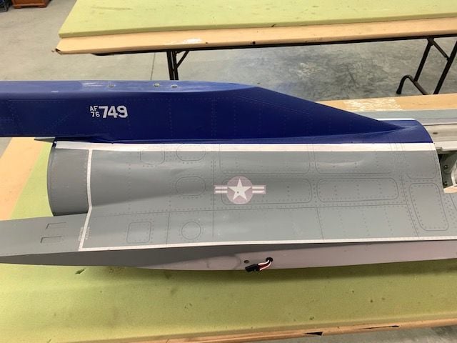
I masked off the white and grey and sprayed the blue. I forgot to take a photo of the blue masking. The blue HD touch up paint was almost a perfect match except for being semi gloss not flat.
I have a can of the 2K matt clear left and will spray it on after this dries a couple of days. I'm pretty happy with the fix. Only thing I had to buy was the touch up paint and I only used about a half teaspoon of that.
Nose gear door and cracks painted with a small brush.
My arts and crafts nozzle project did not come out like I expected but at least it's not gold anymore. The gun metal paint I used to make the wash was not really dark enough to provide much contrast over the aluminum base coat at the trailing edge. So I did the best I could with what was in the paint locker and it's done. Once again why I don't do real scale stuff.
Masking for grey touch up. I spent about 5 mins masking this off and got ready to airbrush. Not so fast. Next I spent about an hour fighting my airbrush and finding out that when I used it to spray the soft lines on the nose back in May some paint got in the trigger slide and it was sticking. Took it all apart and got it cleaned out and started to spray and it quit. Found out paint too thick. Thinned paint and got it done in about 3 min.
I masked off the white and grey and sprayed the blue. I forgot to take a photo of the blue masking. The blue HD touch up paint was almost a perfect match except for being semi gloss not flat.
I have a can of the 2K matt clear left and will spray it on after this dries a couple of days. I'm pretty happy with the fix. Only thing I had to buy was the touch up paint and I only used about a half teaspoon of that.
Nose gear door and cracks painted with a small brush.
My arts and crafts nozzle project did not come out like I expected but at least it's not gold anymore. The gun metal paint I used to make the wash was not really dark enough to provide much contrast over the aluminum base coat at the trailing edge. So I did the best I could with what was in the paint locker and it's done. Once again why I don't do real scale stuff.
Last edited by Viper1GJ; 07-14-2021 at 03:28 PM.
The following users liked this post:
patf (07-15-2021)
The following users liked this post:
Viper1GJ (07-15-2021)
07-15-2021, 01:26 AM
#307

The best technique that works for me to make a nozzle look like they burned and work for sometime is to , step one titanium gold and after it dry overspray with black primer then next day take 0000 steal wool and send it down the primer from the gold under running water, the black flat primer will stay in some areas and the gold will look like burned titanium.
The following users liked this post:
Viper1GJ (07-15-2021)

The following users liked this post:
Viper1GJ (07-15-2021)
07-15-2021, 05:33 PM
#309
Thread Starter
My Feedback: (20)
Hi Thomas,
Thanks.
I have not done it but I know someone who did. They 3d printed a small disc about 1/2" diameter that looked like a small "top hat". The OD of the rim was about 1/2" and the OD of the top part was about 3/8", with about a 1/16" rim. The depth inside the hat was about 1/8" above the base of the rim. A hole was drilled in the center and a barbed fitting was glued in the top of the hat fitting. The appropriate spot for a static source, "inside the red circle", was located on the outside of the jet and a small hole like a #60 bit was drilled through. The rim of the hat fitting was glued on the inside of the fuse over the hole kind of like a suction cup over a hole. Then the barbed fitting was connected to the static input of the sensor. The small chamber inside the top hat fitting allowed static pressure from the outside of the jet to be ported to the sensor inside and give actual outside static pressure not affected by the turbine inside the fuse. The pitot tube only had one tube to the sensor for dynamic pressure.
Hope this can help,
Gary
Last edited by Viper1GJ; 07-15-2021 at 05:36 PM.
07-16-2021, 12:16 PM
#310
Hi Thomas,
Thanks.
I have not done it but I know someone who did. They 3d printed a small disc about 1/2" diameter that looked like a small "top hat". The OD of the rim was about 1/2" and the OD of the top part was about 3/8", with about a 1/16" rim. The depth inside the hat was about 1/8" above the base of the rim. A hole was drilled in the center and a barbed fitting was glued in the top of the hat fitting. The appropriate spot for a static source, "inside the red circle", was located on the outside of the jet and a small hole like a #60 bit was drilled through. The rim of the hat fitting was glued on the inside of the fuse over the hole kind of like a suction cup over a hole. Then the barbed fitting was connected to the static input of the sensor. The small chamber inside the top hat fitting allowed static pressure from the outside of the jet to be ported to the sensor inside and give actual outside static pressure not affected by the turbine inside the fuse. The pitot tube only had one tube to the sensor for dynamic pressure.
Hope this can help,
Gary
Thanks.
I have not done it but I know someone who did. They 3d printed a small disc about 1/2" diameter that looked like a small "top hat". The OD of the rim was about 1/2" and the OD of the top part was about 3/8", with about a 1/16" rim. The depth inside the hat was about 1/8" above the base of the rim. A hole was drilled in the center and a barbed fitting was glued in the top of the hat fitting. The appropriate spot for a static source, "inside the red circle", was located on the outside of the jet and a small hole like a #60 bit was drilled through. The rim of the hat fitting was glued on the inside of the fuse over the hole kind of like a suction cup over a hole. Then the barbed fitting was connected to the static input of the sensor. The small chamber inside the top hat fitting allowed static pressure from the outside of the jet to be ported to the sensor inside and give actual outside static pressure not affected by the turbine inside the fuse. The pitot tube only had one tube to the sensor for dynamic pressure.
Hope this can help,
Gary
that is exactly what i had in mind! Im glad to hear it worked, i am definitely going to have to play around with this.. i have some idea�s. Lol
07-16-2021, 01:26 PM
#311
Thread Starter
My Feedback: (20)
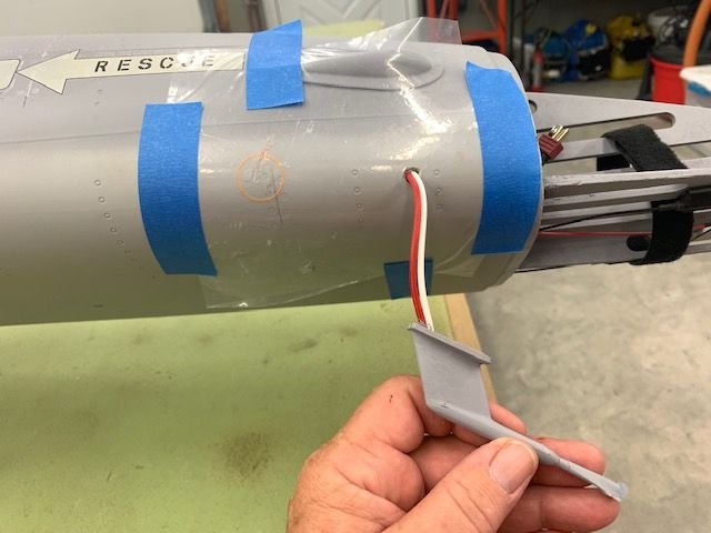
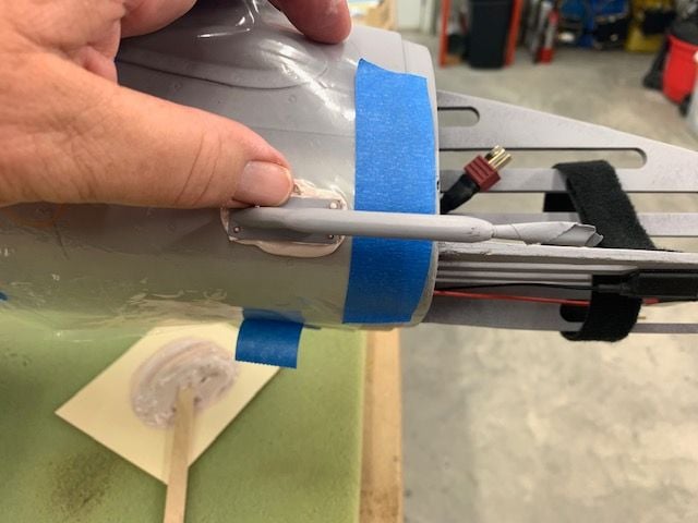
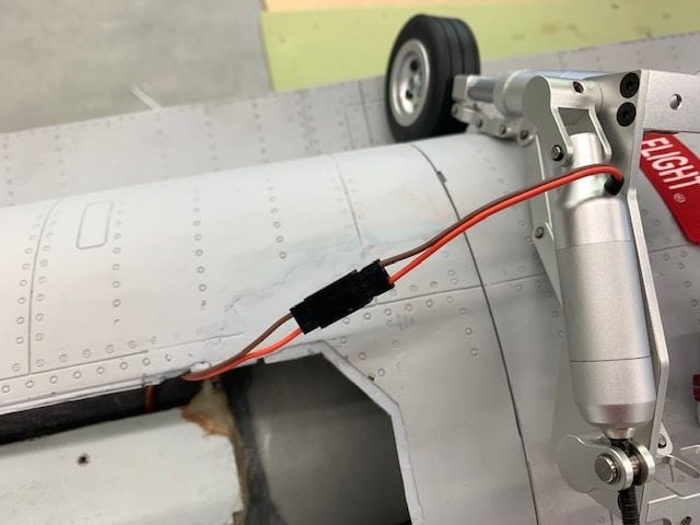
Pitot tube hooked up and tested
Not much shop time the last couple of days but got the pitot tube screwed to side of fuse today
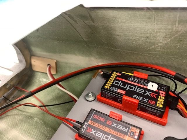
The pressure tubes were routed under the front of the tray and up the right side
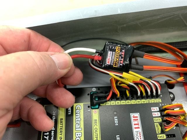
Tubes were cut and connected to the Jeti Mspeed sensor. Red is dynamic and white static.
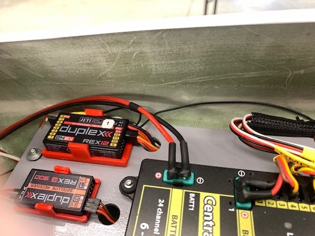
The sensor was tucked out of sight under the right side of the tray where its been sitting since installed.
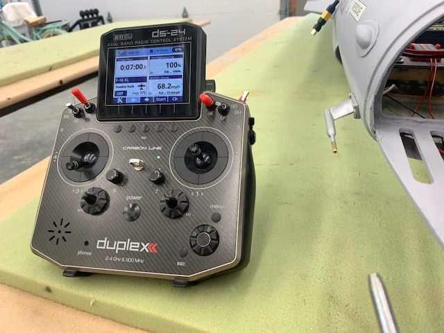
Its always nice when something works the first time! I used the shop air gun to blow some air at the pitot tube and it works great. Here display is reading 68 mph. I'm using my friend Dave's "Speed Announcer" lua program for Jeti. It has several options for call outs including variable call out intervals, airspeed alive, stall, Vref, overspeed, and a stick shaker function. Most importantly it will just call the speed number without all the extra adjectives the Jeti software adds to the call out. It will take data from any telemetry speed source and I have used it with Jeti Mspeed and DIgitech SB-IAS Speed Sensor. I activate the Speed Announcer program with the P10 lever on the back of the transmitter. If you don't want to here it you just turn it off. It's been fun to listen to and play with.
Not much shop time the last couple of days but got the pitot tube screwed to side of fuse today
The pressure tubes were routed under the front of the tray and up the right side
Tubes were cut and connected to the Jeti Mspeed sensor. Red is dynamic and white static.
The sensor was tucked out of sight under the right side of the tray where its been sitting since installed.
Its always nice when something works the first time! I used the shop air gun to blow some air at the pitot tube and it works great. Here display is reading 68 mph. I'm using my friend Dave's "Speed Announcer" lua program for Jeti. It has several options for call outs including variable call out intervals, airspeed alive, stall, Vref, overspeed, and a stick shaker function. Most importantly it will just call the speed number without all the extra adjectives the Jeti software adds to the call out. It will take data from any telemetry speed source and I have used it with Jeti Mspeed and DIgitech SB-IAS Speed Sensor. I activate the Speed Announcer program with the P10 lever on the back of the transmitter. If you don't want to here it you just turn it off. It's been fun to listen to and play with.
Last edited by Viper1GJ; 07-16-2021 at 01:39 PM.
 07-19-2021, 12:35 PM
#313
Thread Starter
My Feedback: (20)
Hi Mark, the short answer for me is no. I just use it for relative speed and it doesn't matter for me whether it is off a little just as long as it is consistent, which it is. However, Dave has calibrated several sensors with bench instrumentation and has found the Jeti Mspeed is consistently fast. So in his lua program there is a correction factor that can be applied and he recommends the Jeti Mspeed factor to be .9. He tells me the Digitech SB-IAS sensor is right on. I have used some of those in my foamies. However, the pitot tube design that comes with the Digitech does not work well with the way I tried to stuff it in a fake F-16 air data probe so I just stuck with the Jeti system.
07-19-2021, 01:06 PM
#314
Thread Starter
My Feedback: (20)
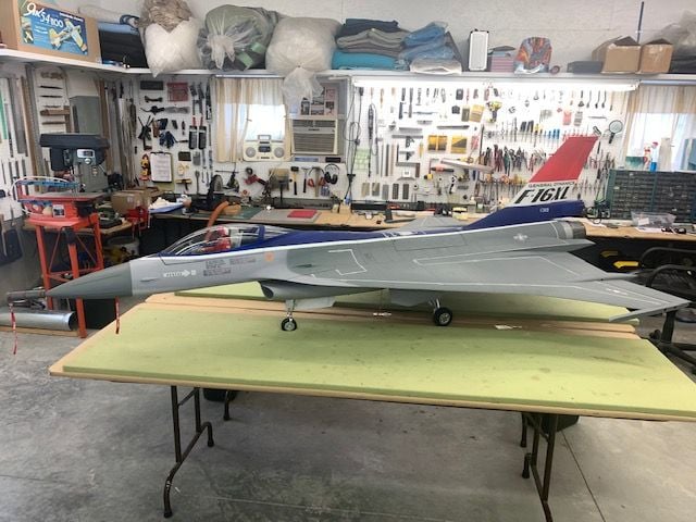
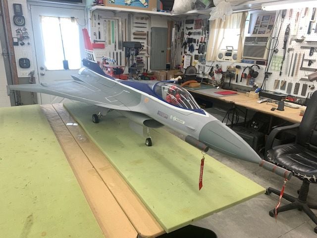
Repairs and upgrades complete, Back In Business!
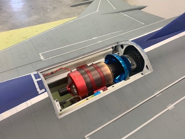
Turbine and pipe reinstalled, connected, and tested, ready to go...
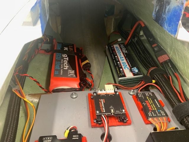
3S flight batteries and AG-63 brake and steering controller installed and tested, ready to go...
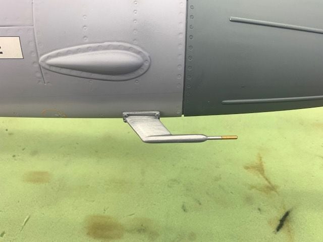
IAS pitot tube installed and tested, ready to go...
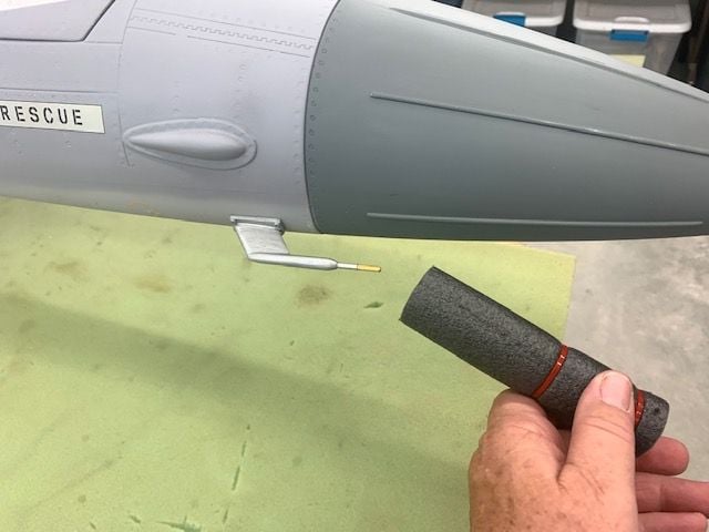
Pitot tube cover made from foam pipe insulation...
Ready to go...
Nozzle repainted and installed, ready to go...
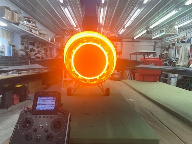
AB lights much brighter now on 3S, working good and ready to go...
Wings installed and tested, everything working, ready to go...
Some maintenance and touch ups done on cockpit and canopy, ready to go...

I still like the way this jet looks, its ready to go...
The only thing left that is not ready to go is the 2K matt clearcoat over the repainted areas to take the sheen off...not so fast, its raining out side and forecast is wet for the next 2 days. Hopefully I can get it shot on this week and get this jet back in the air again soon!
Turbine and pipe reinstalled, connected, and tested, ready to go...
3S flight batteries and AG-63 brake and steering controller installed and tested, ready to go...
IAS pitot tube installed and tested, ready to go...
Pitot tube cover made from foam pipe insulation...
Ready to go...
Nozzle repainted and installed, ready to go...
AB lights much brighter now on 3S, working good and ready to go...
Wings installed and tested, everything working, ready to go...
Some maintenance and touch ups done on cockpit and canopy, ready to go...
I still like the way this jet looks, its ready to go...
The only thing left that is not ready to go is the 2K matt clearcoat over the repainted areas to take the sheen off...not so fast, its raining out side and forecast is wet for the next 2 days. Hopefully I can get it shot on this week and get this jet back in the air again soon!
Last edited by Viper1GJ; 07-19-2021 at 01:16 PM.
07-20-2021, 05:03 PM
#315
Thread Starter
My Feedback: (20)
Flat clear coat applied...all done...ready to FLY!
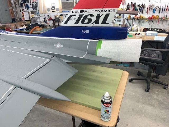
I got a can of Krylon Flat Clear from the hardware store and tested on the bottom of the wing. It was a perfect match to the existing clear coat. The AB nozzle was covered with a paper towel to keep overspray off. The Krylon was perfect for the small touch ups and did not require wasting a full can of 2K clear on a small job. Plus I didn't have to take it outside to use.
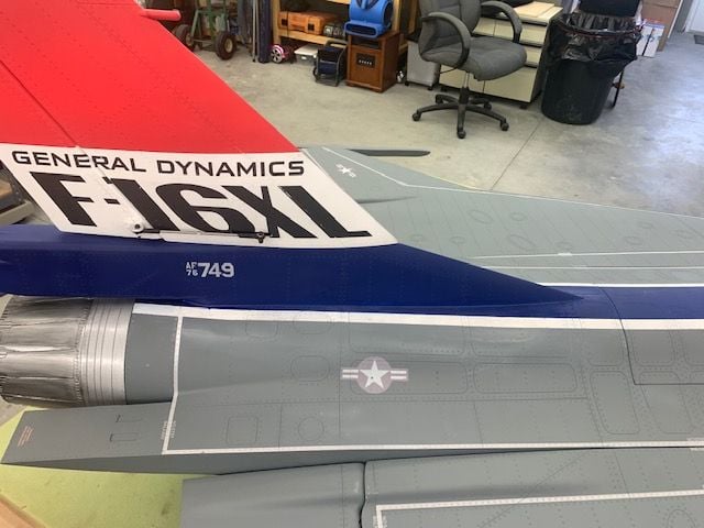
The flat clear over the blue was a perfect match.
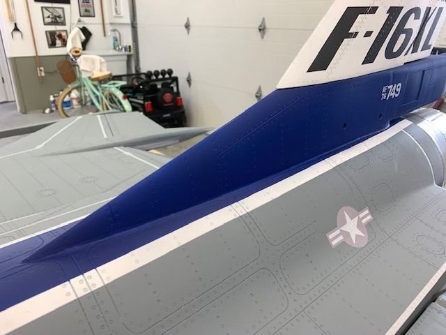
The grey touch up paint is just slightly lighter than the factory paint but it probably wouldn't be noticed if not pointed out. The flat took the sheen off the grey touch up.
No reflection from the sunlight in the door window now.
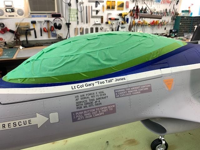
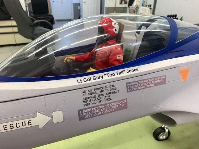
I got the vinyl cutter out and made a canopy name tag. Canopy taped off for clear coat spraying

3 coats of flat clear applied and canopy tape removed. My dumb and stupid pilot still has not found the shoulder harness yet. Maybe I'll show him later!
I got a can of Krylon Flat Clear from the hardware store and tested on the bottom of the wing. It was a perfect match to the existing clear coat. The AB nozzle was covered with a paper towel to keep overspray off. The Krylon was perfect for the small touch ups and did not require wasting a full can of 2K clear on a small job. Plus I didn't have to take it outside to use.
The flat clear over the blue was a perfect match.
The grey touch up paint is just slightly lighter than the factory paint but it probably wouldn't be noticed if not pointed out. The flat took the sheen off the grey touch up.
No reflection from the sunlight in the door window now.
I got the vinyl cutter out and made a canopy name tag. Canopy taped off for clear coat spraying
3 coats of flat clear applied and canopy tape removed. My dumb and stupid pilot still has not found the shoulder harness yet. Maybe I'll show him later!
07-21-2021, 07:20 AM
#316
Thread Starter
My Feedback: (20)
Well not so fast dummy!!!
A prideful, arrogant, cocky, and used up old F-16 pilot named Gary looks at this picture and says "Hey look at me, I put my name on the canopy rail!"
A professional cool and calm F-16 crew chief named Josh looks at this picture and says "Hey your nose wheel is backwards!"...And he is correct!
Truly, it is a credit to many guys like Josh that I am even alive today and I thank them from the bottom of my heart for their service and keeping me safe all those years.
So OK, the nose wheel is on backwards and I did not even notice it. It came assembled backwards from the factory I guess. This is the replacement that GJC sent me at FIF when the first one fell out. I just installed the steering servo in it and put it back in the jet. I never even looked at the scissor links on the front instead of the back of the strut. Josh says his was like that also. I would suggest that JP or Global Knight check these before shipping or installing.
So I have to take it out and turn the nose wheel around so the scissor links are on the trailing edge of the nose strut! ARRRRGH!
 . Great work Gary and thank you for your service!
The following users liked this post:
Viper1GJ (07-21-2021)
07-21-2021, 03:46 PM
#318
Thread Starter
My Feedback: (20)
Grounded and frustrated!
Well my nose wheel was in fact backwards. I tried to make a joke about how I did not see and now had to fix it because it came backwards from the factory. Well I tried to fix it and now I'm really frustrated, and disappointed. It was a disaster and oh yea, it won't work any more and I can't fly. I went from pumped up to deflated.
I found found two set screws on the tiller arm at the top that looked like if you loosened them the strut would rotate 180 degrees and then the set screws could be retightened and done. I could only get to one so I had to remove the nose gear. I had left enough slack in the motor and steering servo wires to be able to just get it out of the gear well so not really a big deal. I loosened the set screws and the strut would rotate a little but not 180 degrees. You could feel a flat spot machined in the top of the strut that was hitting the set screws and stopping rotation. So I unscrewed the set screws almost all the way out and the strut rotated. Great!
I rotated the strut 180 degrees so the scissor links were in the rear. When I started to retighten the set screws disaster struck. I noticed a bunch of tiny ball bearings coming out of the strut joints and falling out. What I later learned was that I had allowed the strut to move up about a millimeter and it opened up 3 ball bearing surfaces and the ball bearings from each started falling out! The bearings are maybe .5 mm in diameter and they are all loose inside the strut bearing surfaces. So now I'm stuck holding the gear trying not to spill any more ball bearings and can't move it because of the wires attached. Great, not!
Last edited by Viper1GJ; 07-21-2021 at 03:49 PM.
07-21-2021, 04:24 PM
#319
Thread Starter
My Feedback: (20)
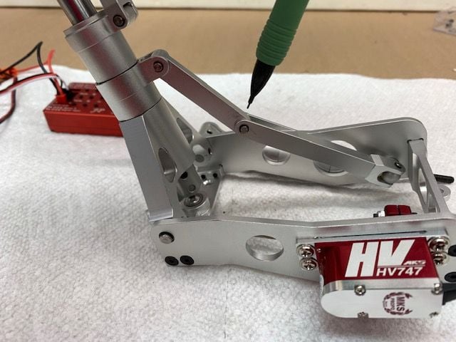
Nose gear fix...not fixed
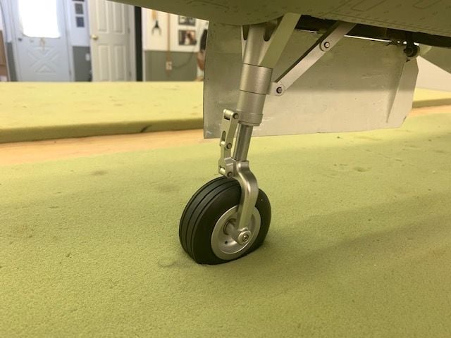
Nose gear scissor links installed on front of strut from factory. Backwards.
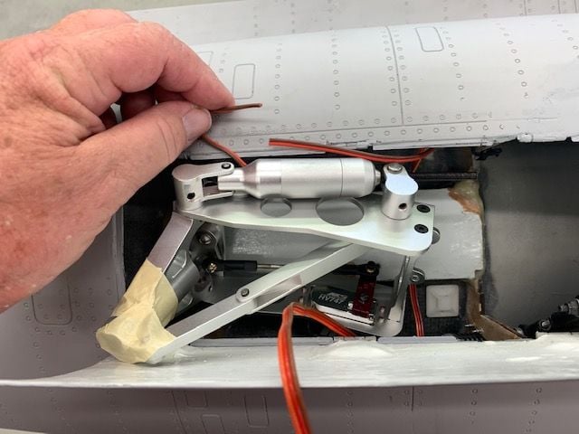
This is after I started loosing all the ball bearings. I taped the bottom to save the ball bearings and had to cut the motor wire because it was impossible to disconnect from the top inside the cockpit area. I was able to disconnect the steering servo.
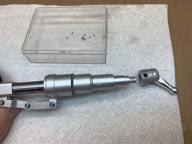
I found out there were 3 bearing races with all the balls loose inside. Some of the balls captured in the box.
Oh boy. JP has such great documentation and manuals! If only I had Known to keep pressure on the strut when turning. What a great design, loose ball bearings in 3 different races, that all have to be kept together by the steering tiller set screws! Yuck.
Taped to keep the balls inside when getting gear out.
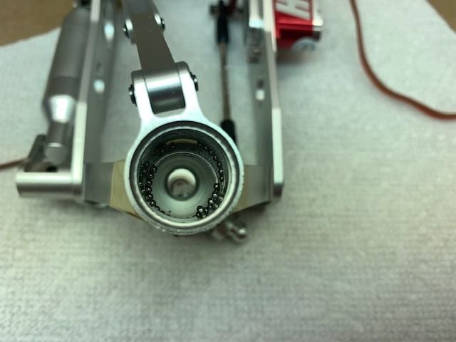
These fell out of the race and inside the strut tube
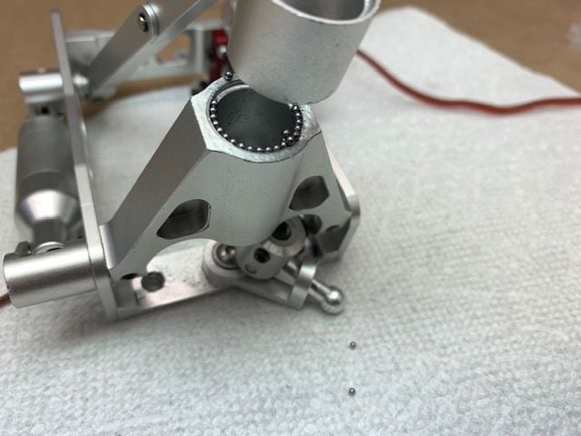
As you can see I lost a lot of ball bearings. I remembered I had the old damaged nose gear so I opened it up to get some ball bearings out of it.
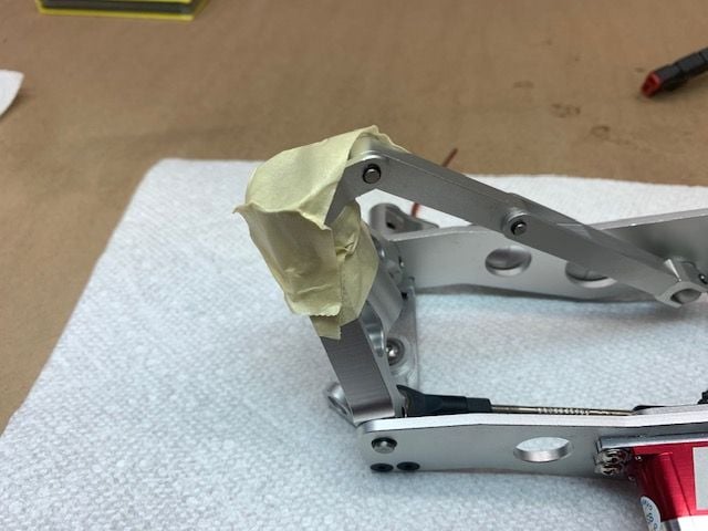
Getting most of them back in with tweezers, tooth pick and fingers. I had to disconnect the retract brace link to assemble the strut. It has a tiny C clip which loves to spring away.
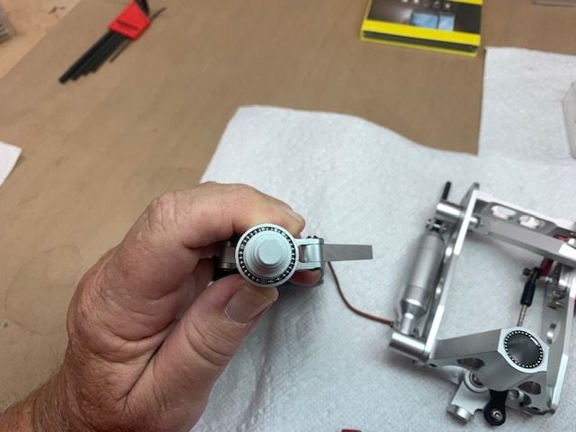
Most of the lost bearings were replaced from the old damaged gear. This process took about 2 hrs. After a couple of failed attempts at getting it back together I learned that taping the joints together as I got them reassembled made it easier to keep the joints from opening up as you put the next part on. Very tedious.
I finally got the gear reassembled. I put a service disconnect plug on the motor wires to make any future service easier.
And here is where the real trouble started. The nose gear will not operate. The motor will try to turn and amp out. I did not change anything on the motor or jack screw. Everything looks the same as all the photos I took of the old one. I can not see any binding. The new plug is working. The motor worked perfect before I reversed the scissor links. I have no clue. There is no manual, no info on any website and no one to call that I know of. I'm loosing confidence in the JP gear and any support for it. I really like this jet but I cant fly it. I'm frustrated and bummed out. Help.
Gary
Nose gear scissor links installed on front of strut from factory. Backwards.
This is after I started loosing all the ball bearings. I taped the bottom to save the ball bearings and had to cut the motor wire because it was impossible to disconnect from the top inside the cockpit area. I was able to disconnect the steering servo.
I found out there were 3 bearing races with all the balls loose inside. Some of the balls captured in the box.
Oh boy. JP has such great documentation and manuals! If only I had Known to keep pressure on the strut when turning. What a great design, loose ball bearings in 3 different races, that all have to be kept together by the steering tiller set screws! Yuck.
Taped to keep the balls inside when getting gear out.
These fell out of the race and inside the strut tube
As you can see I lost a lot of ball bearings. I remembered I had the old damaged nose gear so I opened it up to get some ball bearings out of it.
Getting most of them back in with tweezers, tooth pick and fingers. I had to disconnect the retract brace link to assemble the strut. It has a tiny C clip which loves to spring away.
Most of the lost bearings were replaced from the old damaged gear. This process took about 2 hrs. After a couple of failed attempts at getting it back together I learned that taping the joints together as I got them reassembled made it easier to keep the joints from opening up as you put the next part on. Very tedious.
I finally got the gear reassembled. I put a service disconnect plug on the motor wires to make any future service easier.
And here is where the real trouble started. The nose gear will not operate. The motor will try to turn and amp out. I did not change anything on the motor or jack screw. Everything looks the same as all the photos I took of the old one. I can not see any binding. The new plug is working. The motor worked perfect before I reversed the scissor links. I have no clue. There is no manual, no info on any website and no one to call that I know of. I'm loosing confidence in the JP gear and any support for it. I really like this jet but I cant fly it. I'm frustrated and bummed out. Help.
Gary
Last edited by Viper1GJ; 07-21-2021 at 04:29 PM.
07-21-2021, 05:28 PM
#321
My Feedback: (28)
With JP stuff I have had to use pliers to get the screw to start and after that it seemed to work fine and start and stop where it was supposed to. I basically just turned the jack screw a few turns and then activated the gear and it worked.
Don't know if it will work this time, but just my 2 cents.
Don't know if it will work this time, but just my 2 cents.
07-21-2021, 08:47 PM
#322

My Feedback: (67)
Hi Gary,
Sorry to see you are having problem with the nose gear. could you send both of them back to us and I am getting new sets from JP. Mine is working fine so I would try to find out why yours are not working.
email me for the shipping return address, Thanks,
Mike
Sorry to see you are having problem with the nose gear. could you send both of them back to us and I am getting new sets from JP. Mine is working fine so I would try to find out why yours are not working.
email me for the shipping return address, Thanks,
Mike
07-22-2021, 12:11 PM
#323
Thread Starter
My Feedback: (20)
Hopeful news.
I was out doing some turbine waiver training today and got an email from Mike at GJC. JP sent him a CAD photo and said I had the strut brace linkage assembled wrong. I figured it was probably something I had done wrong. It usually is but I'm not smart enough to see it. I will check it out and report back. Anyway it was great to get a response from JP and GJC in one day. Thanks for the help.
Gary
07-22-2021, 04:33 PM
#324
Thread Starter
My Feedback: (20)
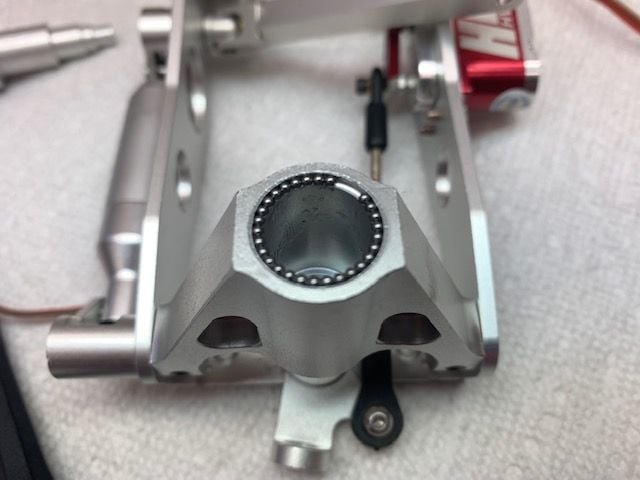
Good News...Back in Business!
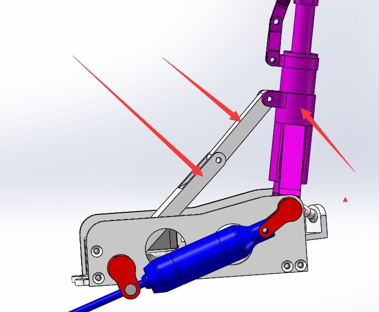
Mike sent me this photo that came from JP. JP looked at my photo and said I had installed the linkage incorrectly and they were right. The locking linkage can be installed with the break angle out or in. I had the break angle out and the linkage would bind and the motor amp out and stop. After 2 hours stacking ball bearings yesterday I just did not see it. Today it is obvious.
The lock linkage break angle has to be in as shown here. Thank JP and Mike at GJC for keeping an eye on me and getting me straightened out.
Works great now. Operator error as usual. I'll get it installed and hope to fly soon.
07-22-2021, 06:31 PM
#325
Gary have you setup the Ag 63 installed in this model? I too fly Jeti and installed one on my JP gear equipped model. I was not able to get the auto config feature work.
I have the unit working correctly and helped a friend do the same. In order to have the gyro move the steering servo to compensate correctly he had to reduce the end points to 80%.
look forward to your response.
I have the unit working correctly and helped a friend do the same. In order to have the gyro move the steering servo to compensate correctly he had to reduce the end points to 80%.
look forward to your response.