


F-16XL ARF by Global Knight Models from Global Jet Club
 05-09-2021, 03:29 PM
#201

Thread Starter
My Feedback: (20)
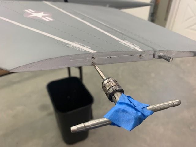
Landing gear testing and controller programming
Hi Dansy, I asked Shane last week and he suggested 1.8 amps on the Xicoy LG15 controller. That was higher than I expected based on my research. I didn't want to smoke the motors right off so I decided to test the output of the JP controller and see what it was putting into the gear motors.
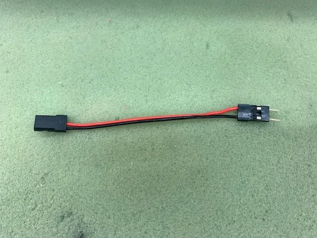
I built this jumper to adapt the Xicoy 3 pin housing with leads on the outside to the 2 pin JP standard.
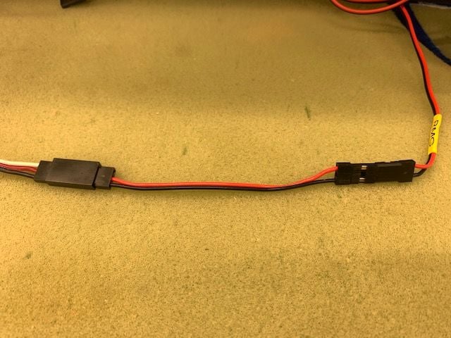
I placed the adaptor inline with the gear wire through my Hanger 9 ammeter to the JP controller.
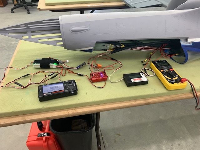
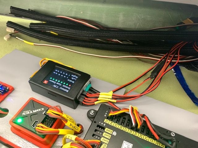
Here is the testing layout. Battery powers the JP controller and servo tester. Ammeter is inline with the gear motor and voltmeter checks the voltage across he plugs. I tested each gear multiple times in both directions. I timed the cycles and recorded the data. Here's what I got and programmed into the LG15 controller.
Nose: .8 amps 9 seconds
Mains: 1.4 amps 13 seconds
Max run time: 14 seconds
Unload time: .10
Voltage: 7.4v
I got all the data programmed into the LG15 and hooked up the board to the jet with all the gear and brakes connected. Held my breath and turned it on. I cycled the gear switch and it worked. Several times. No blue smoke! I adjusted the brakes and both are working smoothly with brake power set at 70%. Happy camper here!
This is my 3rd time using this gear controller. The first 2 were with Electrons and they were preprogrammed and locked. This is the first time I have programmed the controller. It would be a no brainer if you had the amp out data from the gear maker. It clearly says to be careful and not smoke the motors. Next step is to stuff all this stuff in the jet.
Hi Dansy, I asked Shane last week and he suggested 1.8 amps on the Xicoy LG15 controller. That was higher than I expected based on my research. I didn't want to smoke the motors right off so I decided to test the output of the JP controller and see what it was putting into the gear motors.
I built this jumper to adapt the Xicoy 3 pin housing with leads on the outside to the 2 pin JP standard.
I placed the adaptor inline with the gear wire through my Hanger 9 ammeter to the JP controller.
Here is the testing layout. Battery powers the JP controller and servo tester. Ammeter is inline with the gear motor and voltmeter checks the voltage across he plugs. I tested each gear multiple times in both directions. I timed the cycles and recorded the data. Here's what I got and programmed into the LG15 controller.
Nose: .8 amps 9 seconds
Mains: 1.4 amps 13 seconds
Max run time: 14 seconds
Unload time: .10
Voltage: 7.4v
I got all the data programmed into the LG15 and hooked up the board to the jet with all the gear and brakes connected. Held my breath and turned it on. I cycled the gear switch and it worked. Several times. No blue smoke! I adjusted the brakes and both are working smoothly with brake power set at 70%. Happy camper here!
This is my 3rd time using this gear controller. The first 2 were with Electrons and they were preprogrammed and locked. This is the first time I have programmed the controller. It would be a no brainer if you had the amp out data from the gear maker. It clearly says to be careful and not smoke the motors. Next step is to stuff all this stuff in the jet.
 05-09-2021, 04:32 PM
#202

My Feedback: (53)

Shane is part of JP so he should know what he’s talking about….The max would be in the air with the airflow I would think so 1.14 is pretty close and worst case it won’t retract completely ….but still go down I guess…..when I used the JP gear I set them up as per his number and they worked fine but nothing wrong going into the safe side.
05-10-2021, 04:44 PM
#203
Thread Starter
My Feedback: (20)
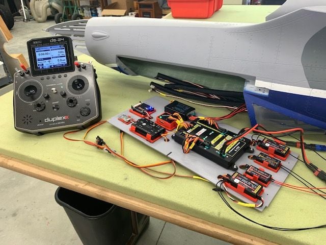
RC board installed
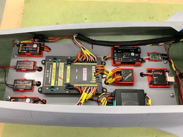
I got the RC board installed and everything connected. I still have to secure the board, wire loom cables, and antennas.
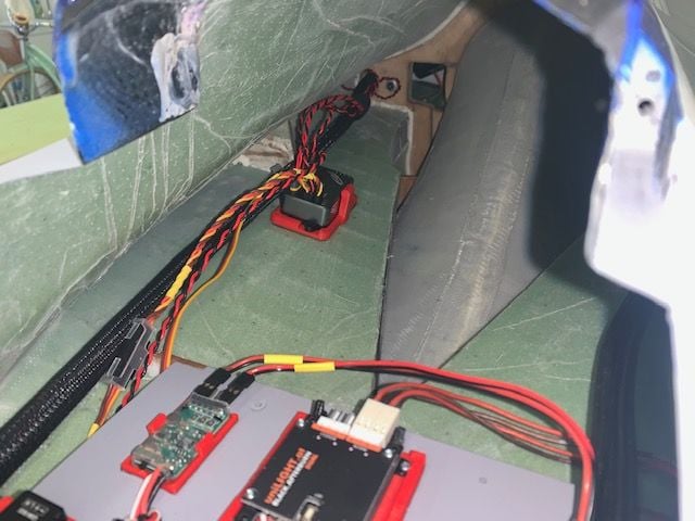
Kingtech DRM located to the rear of the board because the cable from the turbine is too short to have the DRM on the RC board. ECU battery, GSU, and throttle cables run forward from the DRM.
After everything was connected to the board, except for the gear doors, I got the fuse on the cradle and attached the wings and vertical fin. I attached each flight control one at a time to program the radio. I had to reset a couple of the servo arms. When I plugged in the left wing servos they would start oscillating and get worse and worse. It would trigger the 5 amp alarm on the telemetry. Unplug and repeat. I started checking connectors, ran test wires outside the fuse, changed servos, and nothing helped. Then I realized the Cortex Pro gyro was on. I had done the control axis teach in process while it was on the table and not connected to the flight controls. I reprogrammed the gyro and all was well. I guess the gains or something was high enough to start the servos twitching and that started a feedback loop that got worse and worse. Learn something every time! I'll get he gear doors programmed next.
I got the RC board installed and everything connected. I still have to secure the board, wire loom cables, and antennas.
Kingtech DRM located to the rear of the board because the cable from the turbine is too short to have the DRM on the RC board. ECU battery, GSU, and throttle cables run forward from the DRM.
After everything was connected to the board, except for the gear doors, I got the fuse on the cradle and attached the wings and vertical fin. I attached each flight control one at a time to program the radio. I had to reset a couple of the servo arms. When I plugged in the left wing servos they would start oscillating and get worse and worse. It would trigger the 5 amp alarm on the telemetry. Unplug and repeat. I started checking connectors, ran test wires outside the fuse, changed servos, and nothing helped. Then I realized the Cortex Pro gyro was on. I had done the control axis teach in process while it was on the table and not connected to the flight controls. I reprogrammed the gyro and all was well. I guess the gains or something was high enough to start the servos twitching and that started a feedback loop that got worse and worse. Learn something every time! I'll get he gear doors programmed next.
The following users liked this post:
Dansy (05-10-2021)
05-10-2021, 07:48 PM
#204
My Feedback: (28)
RC install continued...
I cracked the fuse sections back apart and installed the final piece of Tygon from air trap to pump and finished the safety wiring. Fuel system is now ready for fuel. I reattached the fuse sections and started working on the equipment tray.
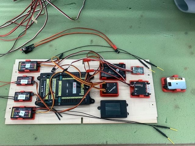
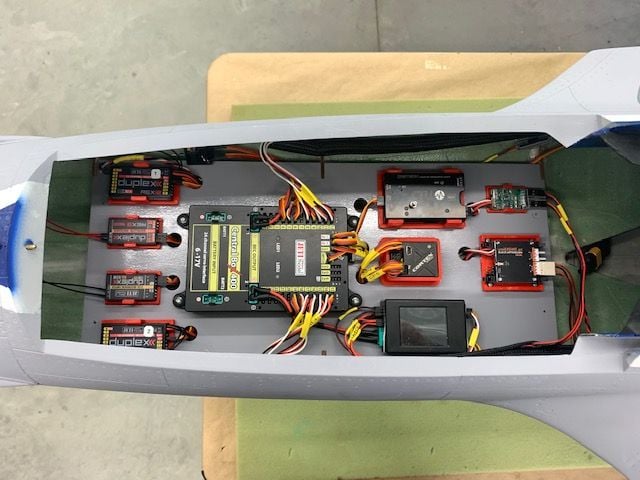
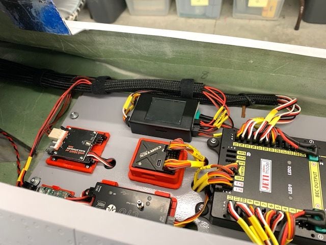
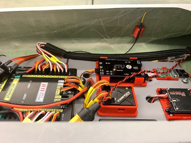
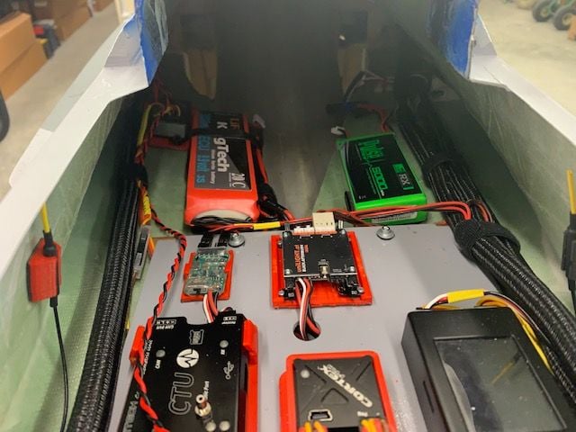
Final equipment tray layout. I kept the 3D printer busy making the part holders. The turbine DRM is not on the tray because the cable from the DRM to turbine is not long enough and I don't want to mess with making it longer. The airspeed module location (seen above the tray) is TBD pending mounting the pitot tube in the scale air data probe location on the lower left side of the nose just behind the radome. Next is to cut wiring holes, mount everytining, and hook it all up.
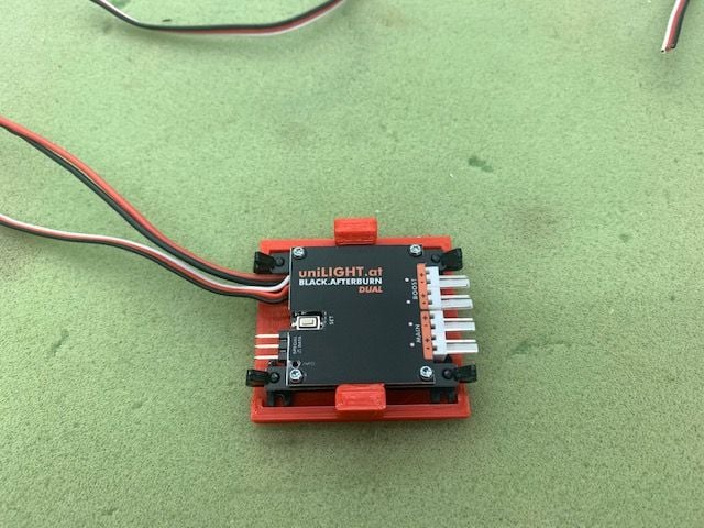
Minor victory for 3D printer novice, I modified a receiver holder to fit the AB LED light controller.
I cracked the fuse sections back apart and installed the final piece of Tygon from air trap to pump and finished the safety wiring. Fuel system is now ready for fuel. I reattached the fuse sections and started working on the equipment tray.
Final equipment tray layout. I kept the 3D printer busy making the part holders. The turbine DRM is not on the tray because the cable from the DRM to turbine is not long enough and I don't want to mess with making it longer. The airspeed module location (seen above the tray) is TBD pending mounting the pitot tube in the scale air data probe location on the lower left side of the nose just behind the radome. Next is to cut wiring holes, mount everytining, and hook it all up.
Minor victory for 3D printer novice, I modified a receiver holder to fit the AB LED light controller.
I would really reconisder that tygon between the pump and UAT with that size turbine.
05-11-2021, 04:21 PM
#205
Thread Starter
My Feedback: (20)
Gary
05-11-2021, 04:39 PM
#206
Thread Starter
My Feedback: (20)
FInal assembly of RC tray and cable looms
I got the RC tray screwed down and secured the cable looms on each side with zip ties and thin Velcro One Wrap.
Both cable looms on left side secured
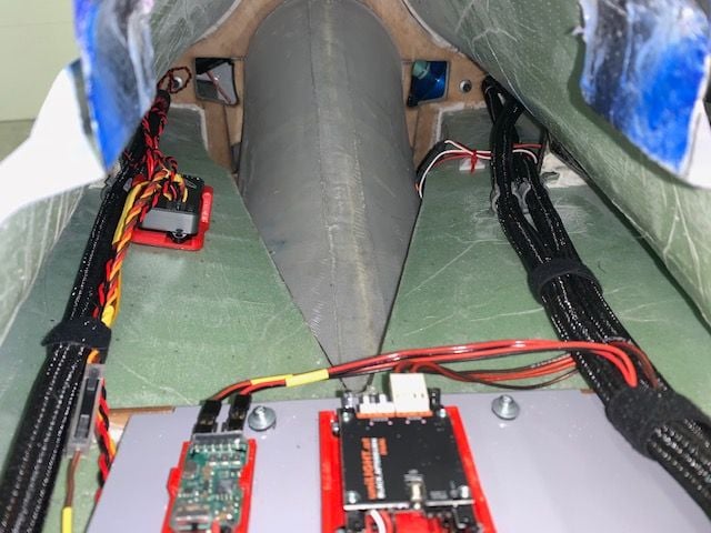
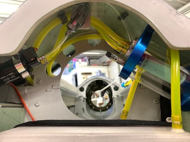
The view aft from the cockpit area
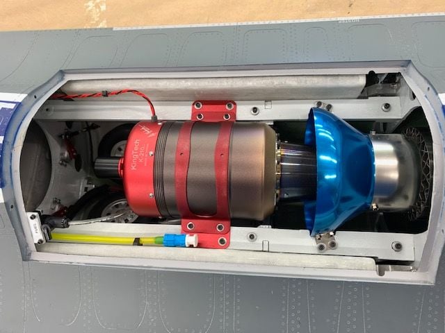
Turbine and pipe mounted. Fuel fill line mounted, turbine data cable secured, and fuel shut off labled.
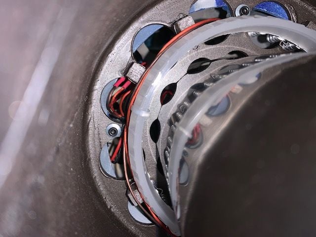
Close up of the AB LED ring and connections. I think the zip ties holding the diffuser ring on should be OK. They are far enough from the pipe and should be OK.
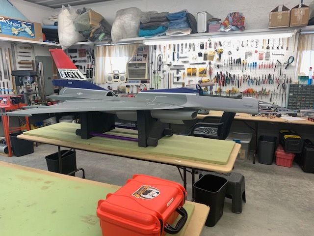
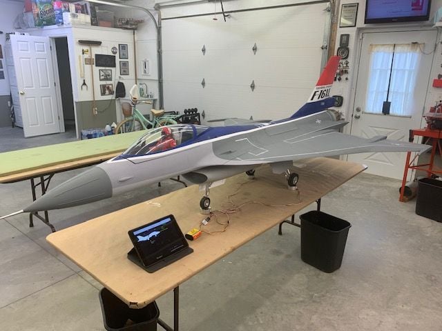
Jet on wheels for final programming and receiver antenna mounting
I got the RC tray screwed down and secured the cable looms on each side with zip ties and thin Velcro One Wrap.
Both cable looms on left side secured
The view aft from the cockpit area
Turbine and pipe mounted. Fuel fill line mounted, turbine data cable secured, and fuel shut off labled.
Close up of the AB LED ring and connections. I think the zip ties holding the diffuser ring on should be OK. They are far enough from the pipe and should be OK.
Jet on wheels for final programming and receiver antenna mounting
05-11-2021, 05:13 PM
#209
Thread Starter
My Feedback: (20)
LOL, I shared this video on a local GroupMe forum today and that's what a few said. I didn't really realize how fast they were till I looked at the video. I was so focused on getting the sequencer timing right I really didn't notice them slamming around so hard. I'll see if I can tame them down a little tomorrow. Thanks.
05-11-2021, 05:32 PM
#210
My Feedback: (53)
LOL, I shared this video on a local GroupMe forum today and that's what a few said. I didn't really realize how fast they were till I looked at the video. I was so focused on getting the sequencer timing right I really didn't notice them slamming around so hard. I'll see if I can tame them down a little tomorrow. Thanks.
The following users liked this post:
Viper1GJ (05-11-2021)
05-12-2021, 02:57 PM
#212
Thread Starter
My Feedback: (20)
See here pages 79-80:
https://www.nasa.gov/sites/default/f..._in_flight.pdf
Last edited by Viper1GJ; 05-12-2021 at 03:00 PM.
05-12-2021, 04:32 PM
#213
Thread Starter
My Feedback: (20)
Antennas and batteries
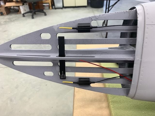
One each of the REX12 2.4 primary and secondary antennas and 900mhz back up antenna mounted under the radome
The other REX12 antennas were mounted under the canopy on the side ahead of the carbon fiber 90 degrees from the front ones
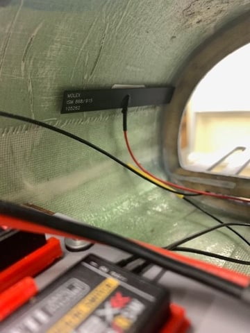
The remaining 900 antenna is inside the forward fuse rotated 90 degrees from the front one.
Another session on the Xicoy CG machine to determine all the combinations of battery placement and CG options. I can move the CG from the recommended factory position to 1.5" forward of that by shifting batteries inside the fuse. Based on recommendations from Josh and Robert I plan to start about 1" ahead of the recommended CG and adjust from there. I can move batteries back to the turbine bay if necessary to get the CG behind the recommended CG if necessary. I will check the CG with fuel in the tanks next.
The start position is ECU battery and one flight battery just behind the RC tray
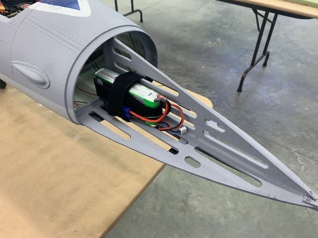
The other flight battery is in the nose
One each of the REX12 2.4 primary and secondary antennas and 900mhz back up antenna mounted under the radome
The other REX12 antennas were mounted under the canopy on the side ahead of the carbon fiber 90 degrees from the front ones
The remaining 900 antenna is inside the forward fuse rotated 90 degrees from the front one.
Another session on the Xicoy CG machine to determine all the combinations of battery placement and CG options. I can move the CG from the recommended factory position to 1.5" forward of that by shifting batteries inside the fuse. Based on recommendations from Josh and Robert I plan to start about 1" ahead of the recommended CG and adjust from there. I can move batteries back to the turbine bay if necessary to get the CG behind the recommended CG if necessary. I will check the CG with fuel in the tanks next.
The start position is ECU battery and one flight battery just behind the RC tray
The other flight battery is in the nose
05-12-2021, 04:54 PM
#214
Thread Starter
My Feedback: (20)
Canopy latch, missile rails, and landing gear
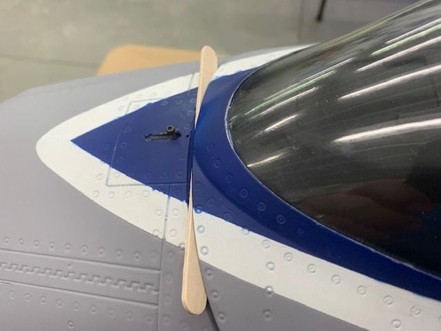
One of the things that bugged me from the start was the gap between the canopy frame and the forward fuse. The problem is that the latch pin does not go deep enough in the canopy frame to securely engage and keep the canopy locked with high speed and or vibrations. This area needs attention in the next production run at the factory.
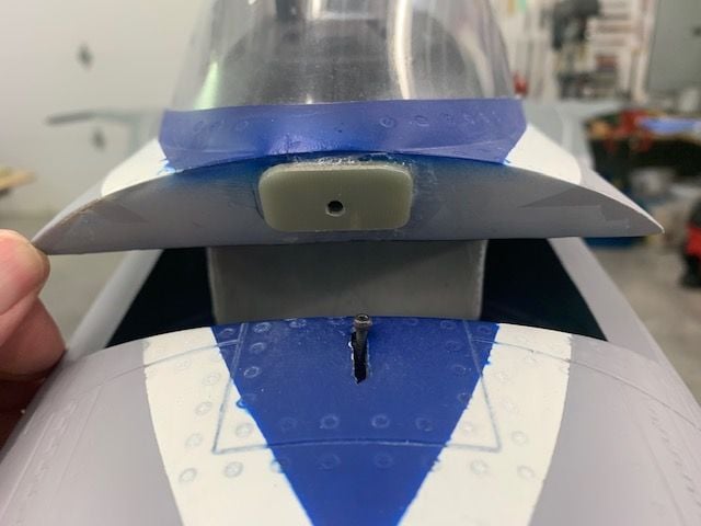
I added a spacer of 1/16" G10 material to allow the pin to securely lock into the canopy frame
I fixed the incorrect angle of the missile rails. After looking at all options I opted for the easy fix. I kept the rear bolt hole in place and allowed the front of the rail to pivot down on the rear bolt. I drilled and tapped another 3mm bolt hole. I used thin CA to harden the new threads since there is no blind nut in the new hole. This did not bind the outboard aileron hinge pin so it worked OK. I accepted a that the top of the tip airfoil will be slightly visible above the top of the missile rail. Other wise it would be too hard to fix in a hurry. The proper fix would be to cut out the rib and blind nuts then fill and reset the bolt holes to center the rail on the tip rib. Not going to happen before FIF in two weeks.
Now the missile rails have the proper negative incidence angle on the ground. I just eyeballed it but it now looks more scale and not so goofy.
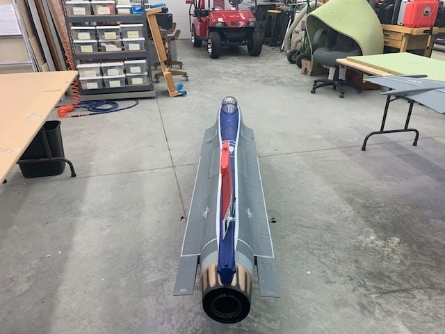
Push test in the shop to center the nose wheel for straight line taxi
I got the landing gear doors slowed down so they move much better now.
Next steps are CG checks with fuel in tanks, fuel pump tests, and turbine start and run up.
One of the things that bugged me from the start was the gap between the canopy frame and the forward fuse. The problem is that the latch pin does not go deep enough in the canopy frame to securely engage and keep the canopy locked with high speed and or vibrations. This area needs attention in the next production run at the factory.
I added a spacer of 1/16" G10 material to allow the pin to securely lock into the canopy frame
I fixed the incorrect angle of the missile rails. After looking at all options I opted for the easy fix. I kept the rear bolt hole in place and allowed the front of the rail to pivot down on the rear bolt. I drilled and tapped another 3mm bolt hole. I used thin CA to harden the new threads since there is no blind nut in the new hole. This did not bind the outboard aileron hinge pin so it worked OK. I accepted a that the top of the tip airfoil will be slightly visible above the top of the missile rail. Other wise it would be too hard to fix in a hurry. The proper fix would be to cut out the rib and blind nuts then fill and reset the bolt holes to center the rail on the tip rib. Not going to happen before FIF in two weeks.
Now the missile rails have the proper negative incidence angle on the ground. I just eyeballed it but it now looks more scale and not so goofy.
Push test in the shop to center the nose wheel for straight line taxi
I got the landing gear doors slowed down so they move much better now.
Next steps are CG checks with fuel in tanks, fuel pump tests, and turbine start and run up.
Last edited by Viper1GJ; 05-12-2021 at 05:05 PM.
The following users liked this post:
Dansy (05-13-2021)
05-13-2021, 04:58 PM
#215
Thread Starter
My Feedback: (20)
Fuel system calibration.
I added fuel one liter at a time and marked the tanks for each liter. This allows me to easily calibrate the CTU fuel factor after each flight. I also checked the weight and CG as each tank filled. Empty weight with air trap full is 37.26 lbs. Full fuel weight is 45.7 lbs with 4.7 liters fuel. I did not notice before but the saddle tanks are not centered on the recommended CG. About 2/3s of the saddle tanks are behind the recommended CG. As a result the CG will shift aft 9mm as the fuel burns from the front tank. The most aft CG is when the front tank is empty and both saddle tanks are full. The CG moves back forward as fuel is burned from the saddle tanks. With 1 liter remaining in the right tank the CG is exactly the same as when full for take off.
The recommended CG in the build guide is 137mm forward of the main gear. I plan to test fly about about 1/2" to 3/4" ahead of the recommended CG based on recommendations from Josh and Robert in Colorado. With my current battery placement my take off CG is 153mm. Landing with 1 liter remaining in the right saddle tank is the same at 153mm. As the front tank burns out the CG will shift back 9mm or about 3/8" to 144mm. Then as the side tanks burn out the CG shifts back forward to 153mm. I am comfortable with this data as it is conservative and forward of the recommended CG. I can easily adjust this range by moving batteries inside the fuse.

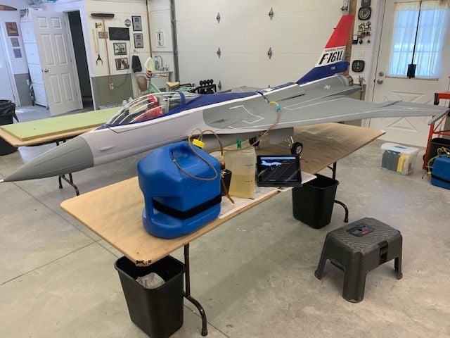
Priming the fuel line to the turbine and running the fuel pump while banging on the top of the fuse where the air trap is mounted with my hand to dislodge any bubbles. I got some at first and after that there was a solid flow of fuel with no air bubbles. The fuel runs back into the jug.

The new K-210G4 started and ran perfectly. The first start was a little slow but spooled up ok after all the fuel lines were filled. The second start was quick and smooth. I did not run at high power since it was hard to hold by myself. Next step was full power run ups and range checks outside.
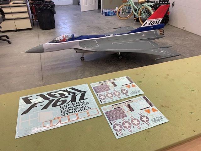
While I was preparing to move outside the decals were delivered. I haven't done waterslide decals since I was a kid. Got to read up on that.
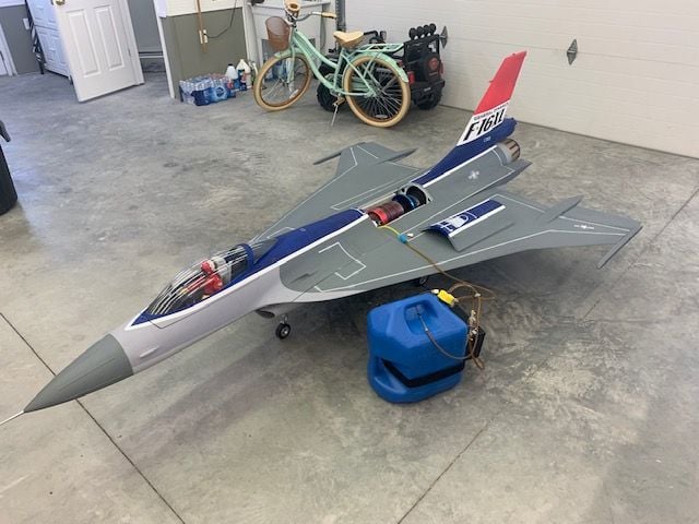
Fueling up so I can calibrate the CTU after the ground run.
I moved the jet outside and tied it to the shop building. I placed markers 150' away for range checks from the nose and tail and to the left and right
Ready to start. I quickly discovered as I ran up the power the strap stretched and raised up into the exhaust.
I rerouted the straps underneath and angled the tail slightly away from the straps. Worked good. I then went to all 4 quadrants and did an idle and full power range check. When all checks were complete I untied the jet and did taxi and brake tests in the yard. I had to dial down the nose wheel steering and add more expo. The brakes checked ok. The jet is very top heavy and with a very narrow wheel base and it is easy to tip in a turn. Don't ask! After taxi test complete I tested the turbine fail safe shutdown. It worked ad expected. After cool down and before turning off the electrical power I got an initial fuel factor for the CTU by checking the fuel remaining and adjusting the fuel factor in the CTU menu. So far so good.
Next stop is the flying field. Hopefully this weekend or early next week depending on schedules and weather.
05-14-2021, 08:09 AM
#218
Do some research on how plastic modelers apply decals! They ALWAYS clearcoat w/ gloss before application. No waterslide decal will sit " flat' on a non glossy finish....It will have white spots on the raised parts if you don't....hope this helps....and what he said..Microsol and Microset were designed for this application!
Last edited by jetjon; 05-14-2021 at 08:11 AM. Reason: more info
05-14-2021, 09:28 AM
#220
the usual technique is to gloss coat, apply the decals w/ the solvent system and the clear over w/ a matte finish�.
Last edited by jetjon; 05-14-2021 at 11:01 AM. Reason: Adding more info
05-14-2021, 12:33 PM
#221

FInal assembly of RC tray and cable looms
I got the RC tray screwed down and secured the cable looms on each side with zip ties and thin Velcro One Wrap.
Both cable looms on left side secured
The view aft from the cockpit area
Turbine and pipe mounted. Fuel fill line mounted, turbine data cable secured, and fuel shut off labled.
Close up of the AB LED ring and connections. I think the zip ties holding the diffuser ring on should be OK. They are far enough from the pipe and should be OK.
Jet on wheels for final programming and receiver antenna mounting
05-14-2021, 05:12 PM
#222
Thread Starter
My Feedback: (20)
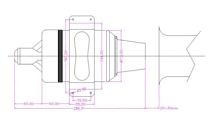
I used 25mm from nozzle to pipe (not the bell) as shown in my post #119. I've been using 25mm on the K-210 since they came out several years ago. I got it from the diagram in the Kingtech manual. I use 30mm for the 300-320N turbines I've run. I used to use 3/4" when I had Jetcat 120-160s.
Thanks for checking,
Gary
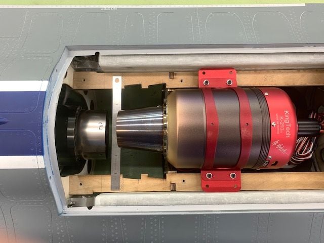
Trailing edge of the turbine nozzle is set 25mm ahead of the pipe and mounting positions marked
Last edited by Viper1GJ; 05-14-2021 at 05:29 PM.
05-14-2021, 05:24 PM
#223
Thread Starter
My Feedback: (20)
Thanks
Gary
05-15-2021, 07:17 AM
#224
Plastic modelers used to use Future floor wax (for the gloss coat prior to applying the decals) sprayed on w/an airbrush ......don't know if that is still valid ,but no other paints would react to it...
Last edited by jetjon; 05-15-2021 at 07:18 AM. Reason: more info
05-15-2021, 02:41 PM
#225
Thread Starter
My Feedback: (20)
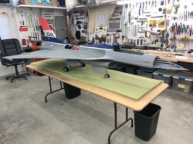
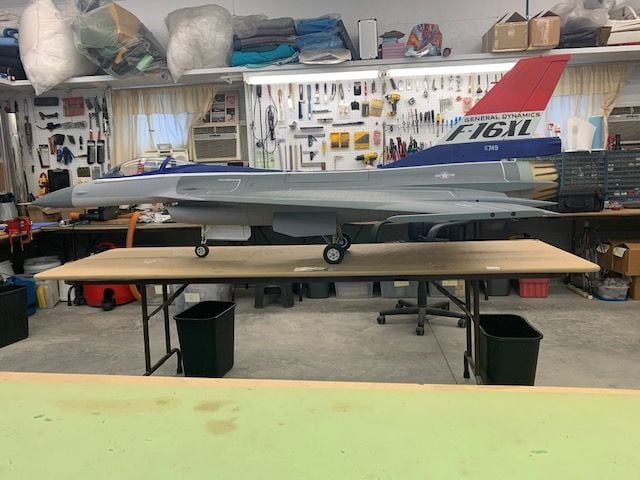
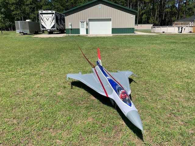
F-16XL Test Flight Prep
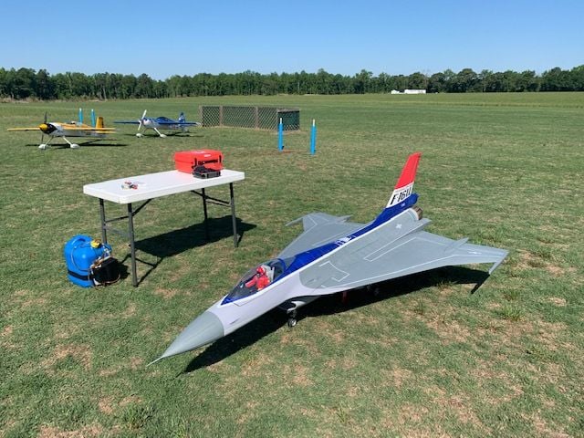
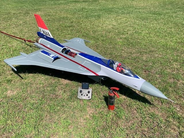
Post assembly, ready for fuel.
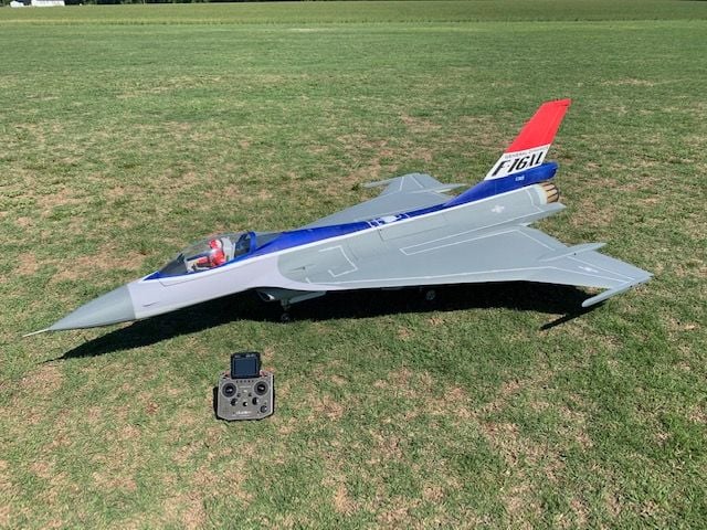
Happy snaps prior to start.

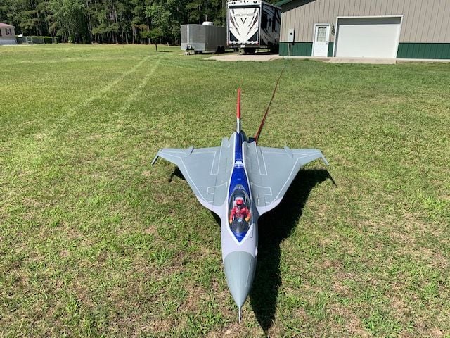
A beautiful day, 78 degrees, winds light and variable
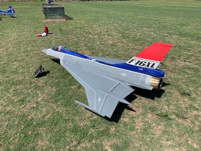
Jet looks good
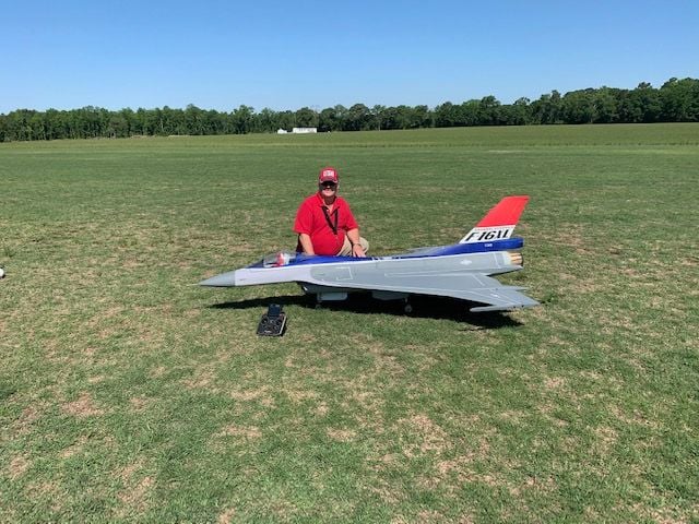
The short fat guy is me!
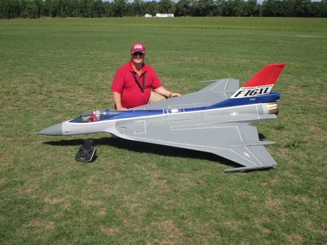
Ready to fly!
Post assembly, ready for fuel.
Happy snaps prior to start.
A beautiful day, 78 degrees, winds light and variable
Jet looks good
The short fat guy is me!
Ready to fly!
Last edited by Viper1GJ; 05-15-2021 at 02:47 PM.