


F-16XL ARF by Global Knight Models from Global Jet Club
 03-24-2021, 03:16 PM
#1

Thread Starter
My Feedback: (20)
Anything F-16XL welcome here!
I am starting a build thread for the F-16XL ARF by Global Knight Models. It is imported and sold by Global Jet Club. Please post anything you have about this new F-16XL model here.
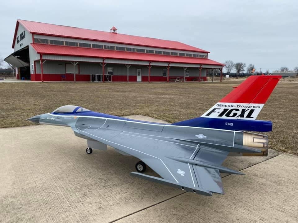
This is one of the prototypes flown by Ali.
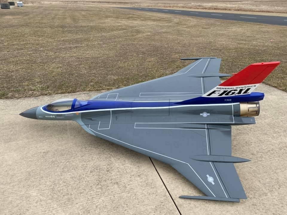

Nice size jet but done in 1/6 scale so it is not too hard to pick up and move around.
I am starting a build thread for the F-16XL ARF by Global Knight Models. It is imported and sold by Global Jet Club. Please post anything you have about this new F-16XL model here.
This is one of the prototypes flown by Ali.
Nice size jet but done in 1/6 scale so it is not too hard to pick up and move around.
Last edited by Viper1GJ; 03-24-2021 at 03:19 PM.
 03-24-2021, 03:58 PM
#2
Thread Starter
My Feedback: (20)
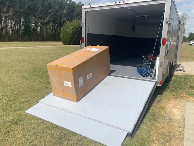
Got notice from the shipper that my jet arrived at the regional freight terminal but it would be several days till it could be delivered to the house. I did not want to wait so I drove to get it.
It's a big box and weighs 60 lbs without the pallet it was on.
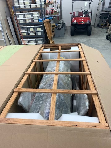
First look! 1st thought is it looks like an F-16 and it's the correct color! 2nd thought is it's packed real well. Wood cage inside box with custom cut EPO foam packing on each end.
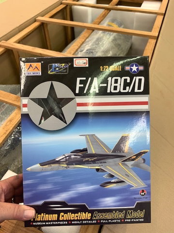
I saw a loose box and thought it was parts. It turned out to be an F-18 display model with stand. Nice touch of swag!
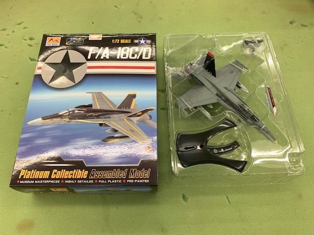
I opened the model to check it out and found a folded piece of paper inside.

Got a personal note from Global Knight! Nice touch. Thanks!
The following users liked this post:
458destroyer (02-03-2023)
03-24-2021, 04:15 PM
#3
Thread Starter
My Feedback: (20)
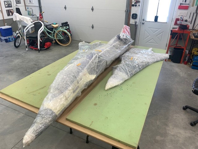
Just 5 pieces in bubble wrap inside the box. Forward fuse, aft fuse, vertical tail, left and right wings. No parts box. I hope the fuse is stuffed full of parts!
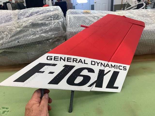
Unwrapped the tail and discovered the finish is a very flat matt finish. Not bad just different than I expected. I've been used to the SM and BVM gloss clear coat. It has a slight sheen if viewed at low angle to light. It actually reminds me of some or the F-16 jets I used to fly. I can't remember what the real XL was like since I only saw it once back in the early 80's. You won't get sun glint from this finish!
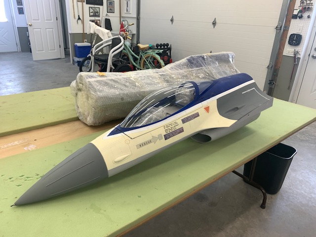
Forward fuse unwrapped next. Looks like fuse is stuffed with parts. I was not expecting the cream color. It is supposed to be a light grey. This looks like a factory paint shop mistake. This destroys the scale look of the jet. It will be hard to fix. TBD.
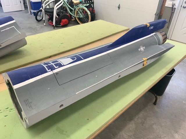
Rear fuse unwrapped next.
It is stuffed full parts. Also looks like an explosion in a hook up wire factory. Looks like it is pre wired but no plugs on wire ends.
Last edited by Viper1GJ; 03-24-2021 at 05:52 PM.
03-24-2021, 04:36 PM
#4
My Feedback: (2)
Viper - My friend has the 1st XL built out of the 2 we ordered and he's hoping the maiden takes place his this coming weekend, he's using JR 8955 2K servos and an ACEx 220 turbine. His XL came out to around 36lbs with the UAT and header tank with some fuel in it.
My build will hopefully start tomorrow, I will be using Savox SB-2290SG's, ACEx 190 turbine and I could either way on a Cortex Pro or AS3000 gyro.
Only feedback we have given is the 120oz tanks are not enough, you will need a header tank. I'm debating on if I want to install one now and see what flight time I get since the ACEx turbines are very fuel efficient, but in the front of the aft fuse you can install a 34oz tank no problem, but its probably smart to install one since I'm not looking for short flight times. Plenty of room to work with inside the jet so that's nice.
Good luck on the build
Last edited by F900; 03-24-2021 at 04:47 PM.
The following users liked this post:
jkeze (03-25-2021)
03-24-2021, 05:26 PM
#5
Thread Starter
My Feedback: (20)
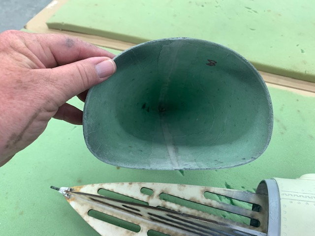
Hi F900, Thanks for the info. My turbine is a K210G4. I agree 120oz is not enough. I was talking to my friend Keith tonight about a 3D printed header tank to fit in the space at the front of the rear fuse section. I can print it if he can send me the files he draws. I gave him some rough measurements and he sent me this pic of a rough draft design.
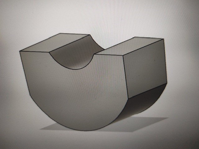
Estimated volume is about 55-60 oz.
Estimated volume is about 55-60 oz.
03-24-2021, 05:32 PM
#6
Thread Starter
My Feedback: (20)
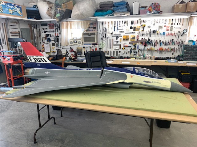
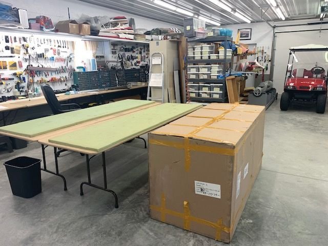
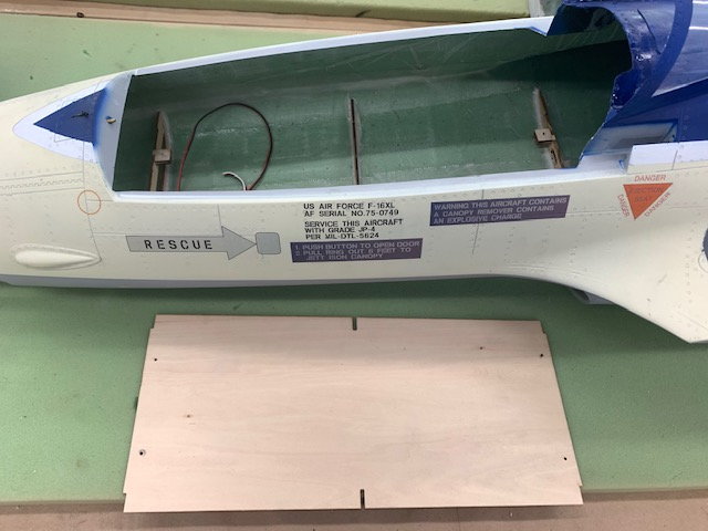
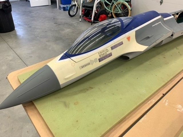
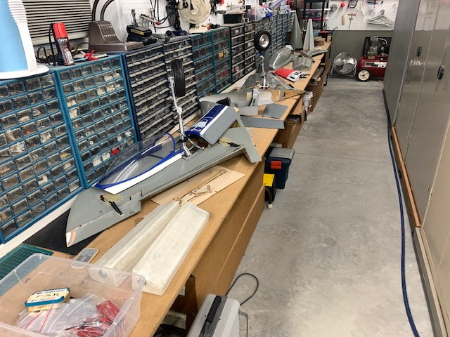
Here's the mock up. The tables are 8' long.

The tables are 30" wide so 60" total.
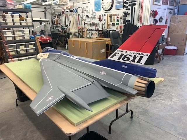
This looks like a fun jet. I'm really happy with the size at 1/6 scale. I've been hosting the SM and BVM 1/5 F-16s the last few years and this one will be much easier to pick up and move around.
03-24-2021, 05:46 PM
#7
Thread Starter
My Feedback: (20)
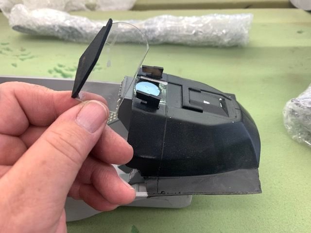
Forward fuse was stuffed with the cockpit and other parts. I unwrapped the cockpit and found the HUD was broken off and one side piece was missing. Also had some glue on the HUD glass.
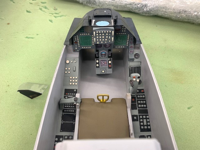
Nice cockpit is provided. However it is the wrong cockpit for this jet. The XL was a Block 10 A model F-16 built in the early 80's and had round dial steam guages, and the radar scope between your legs. It did not have the dual MFD displays that came later with the Block 20-25 C model jets. I discussed this with Mike last December but he said production was already underway with the C model glass cockpits so that is what would come with the kit.
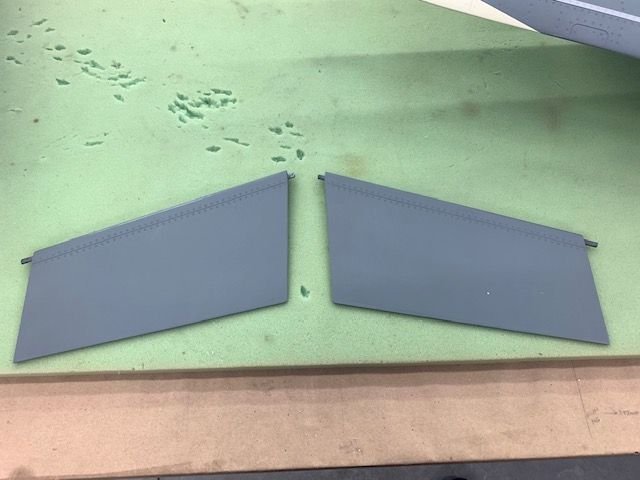
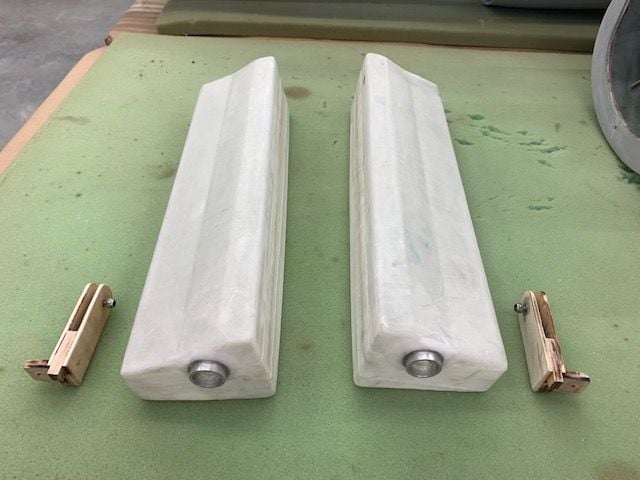
Outboard elevons
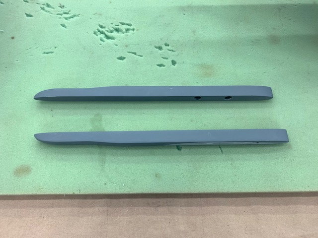
Missile rails that hold the outboard elevon hinge pins

Rear fuse stuffed with pipe
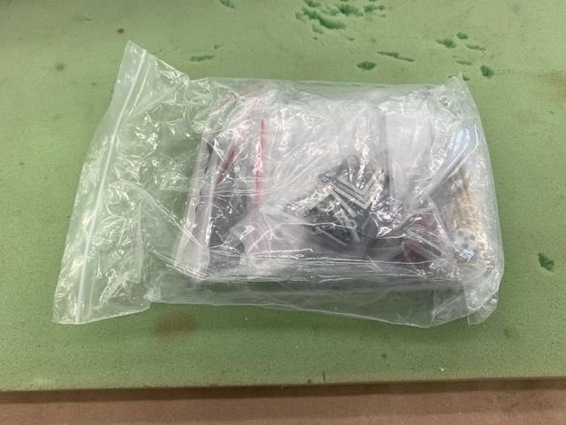 \
\Finally found the parts bag in the rear fuse.
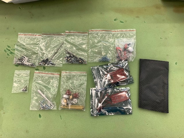
Several sets of hardware, tank hardware, JP brake controller, JP gear controller, and some fake carbon fiber vinyl for the equipment tray. No instructions or manual is included.
03-24-2021, 06:07 PM
#8
My Feedback: (2)
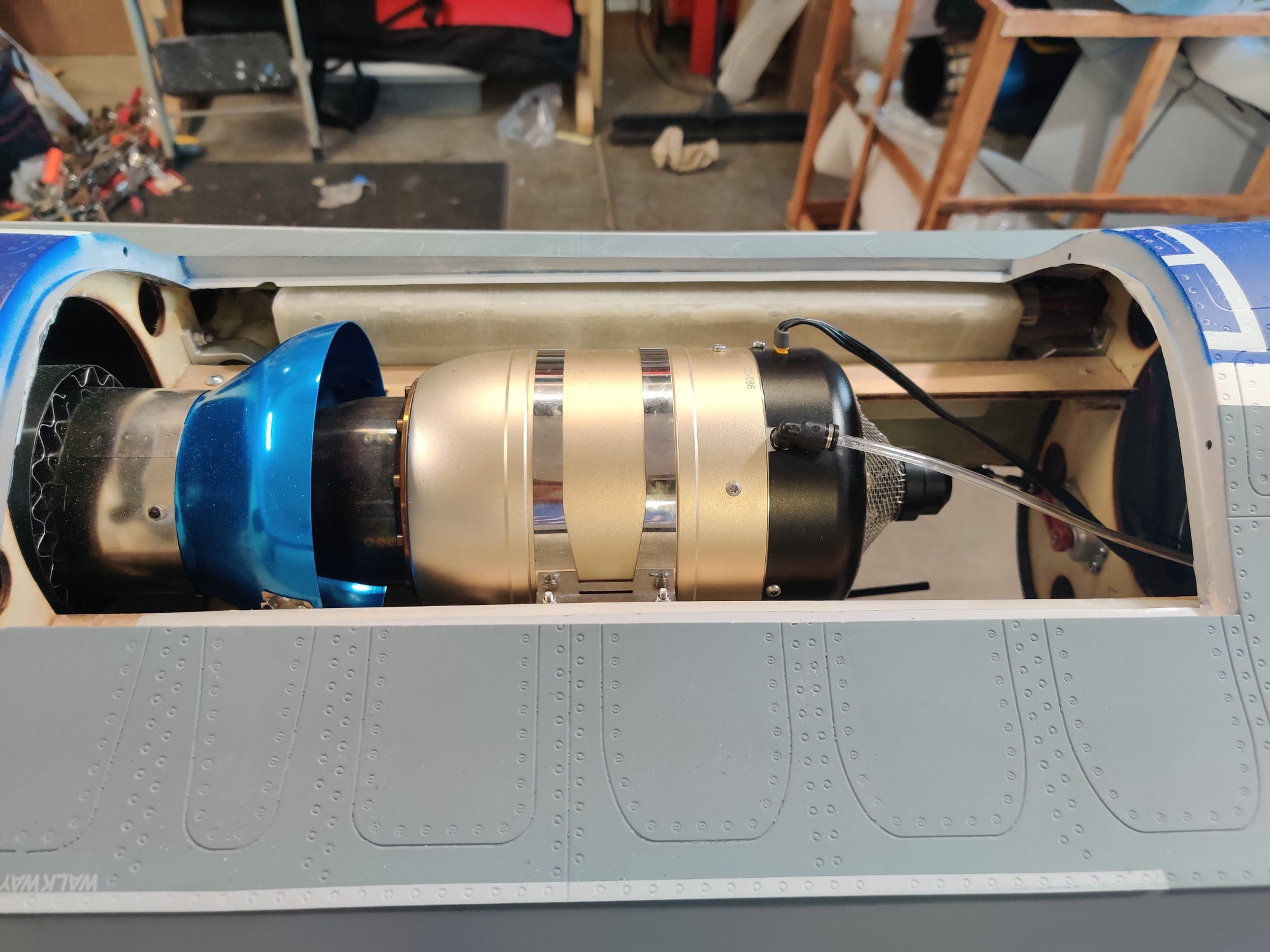
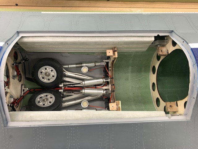
So this is were things get interesting, myself and buddy have chatted about the size of the header tank. Bigger you use the more front weight your going to have on landing since the current fuel configuration will empty the 2 60oz tanks which is either just on the CG or slightly aft, all your remaining fuel will be forward of the CG. Given that the jet is a big delta wing with lifting body it might not matter as much, but our preference is to keep as much weight out of the front which is why we are keeping the header tank at no more than 32oz. By doing that the 220 was moved aft as far as possible from the recommended location, I will have my 190 positioned in the same location just to compare.
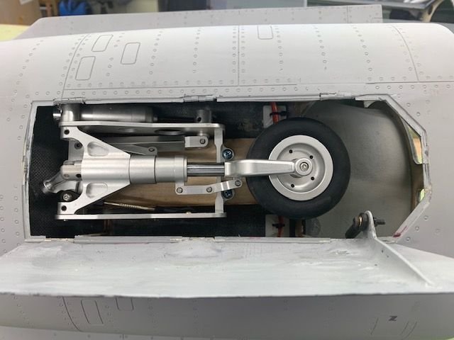
The below picture shows you for reference the location of the 220, by doing this the nose is 0.5lbs heavy using the Xicoy CG meter which is better than expected and for now were quite happy with the result since we don't have to add additional counter weight, also is not shown in order to achieve this CG the ECU battery and JP brake controller battery are positioned on either side of that wooden rail just in front of the turbine. I'll provide you will better feedback once the 1st few flights have taken place to get a better idea on CG placement.
The below picture shows you for reference the location of the 220, by doing this the nose is 0.5lbs heavy using the Xicoy CG meter which is better than expected and for now were quite happy with the result since we don't have to add additional counter weight, also is not shown in order to achieve this CG the ECU battery and JP brake controller battery are positioned on either side of that wooden rail just in front of the turbine. I'll provide you will better feedback once the 1st few flights have taken place to get a better idea on CG placement.
Last edited by F900; 03-24-2021 at 06:14 PM.
03-24-2021, 06:11 PM
#9

My Feedback: (3)
Bummer on the cream colored forward fuse...that’s a challenging one to easily fix and defeats the purpose of a pre-painted jet.
Maybe they will step up and send a correctly painted forward fuse section in return for the cream colored one. (Hint, hint!)
Looking forward to seeing the progression of the build!
JS
Maybe they will step up and send a correctly painted forward fuse section in return for the cream colored one. (Hint, hint!)
Looking forward to seeing the progression of the build!
JS
03-24-2021, 06:11 PM
#10
Thread Starter
My Feedback: (20)
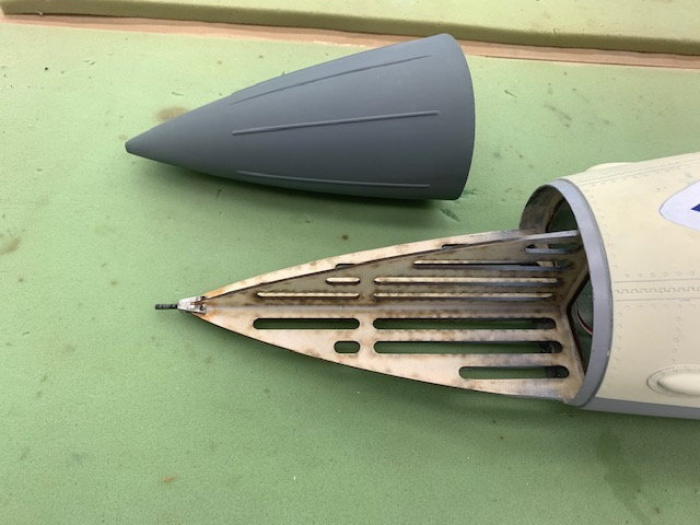
Radome is held on by a threaded pitot tube.
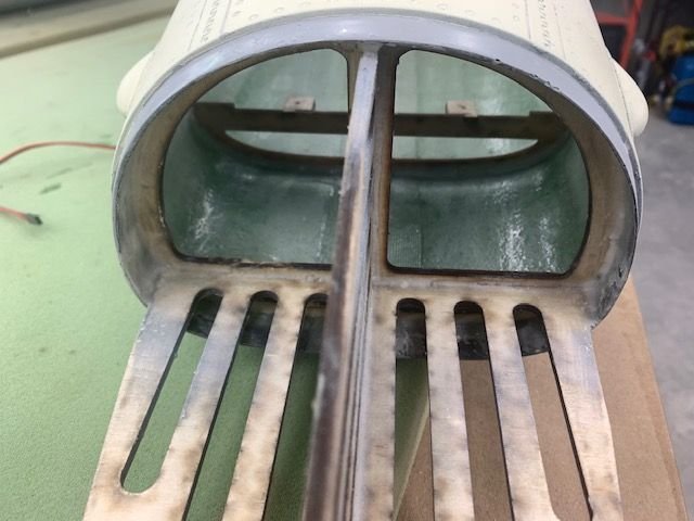
Frame is fixed and non removeable as in SM and BVM models
Equipment tray removed
Space under tray for wires. Wires shown here are nose retract, steering, and nose light
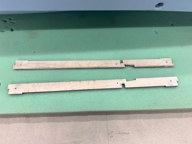
Turbine rails held in place by 3 screws.
Turbine mounting rails removed. Tanks held in by rails and a wood bracket.
Tank holding bracket is held on by one bolt and nut in former
Tank bracket removed
Tank slides out
Im told the tanks hold about 60 oz each. That is only about 120 total which is a little less that I would like.

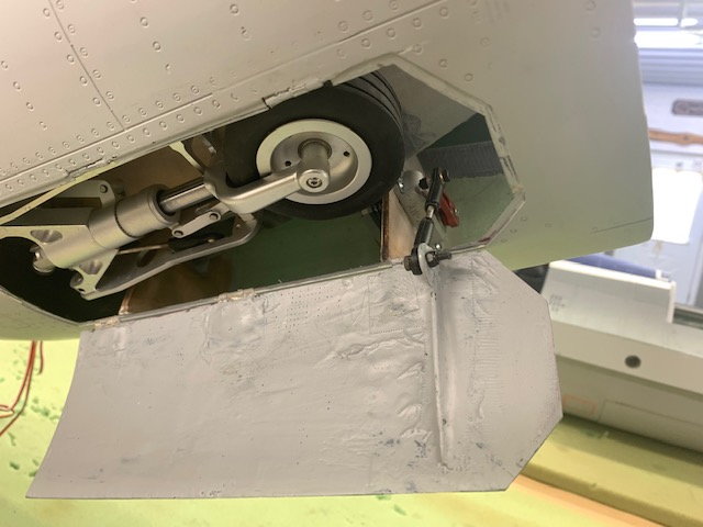
Main gear doors
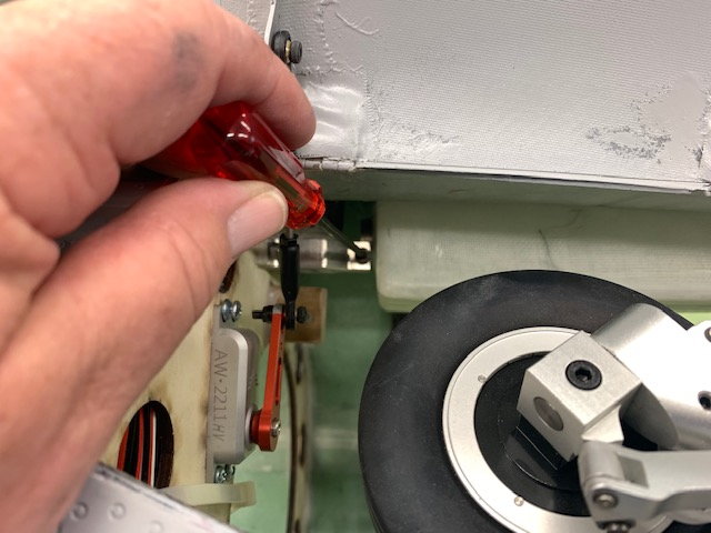
The front wing clamp screw is accessed from the bottom through the gear well
03-24-2021, 06:21 PM
#11
My Feedback: (2)
Bummer on the cream colored forward fuse...that’s a challenging one to easily fix and defeats the purpose of a pre-painted jet.
Maybe they will step up and send a correctly painted forward fuse section in return for the cream colored one. (Hint, hint!)
Looking forward to seeing the progression of the build!
JS
Maybe they will step up and send a correctly painted forward fuse section in return for the cream colored one. (Hint, hint!)
Looking forward to seeing the progression of the build!
JS
Last edited by F900; 03-24-2021 at 06:23 PM.
The following users liked this post:
jsnipes (03-24-2021)
03-24-2021, 06:24 PM
#12
Thread Starter
My Feedback: (20)
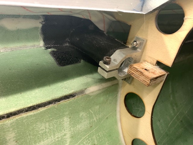
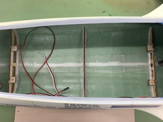
Rear wing tube attached with CF to fuse and formers
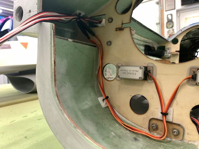
Same for front wing tube. Servo wires are run thru the braided sleeves and glued to the fuse. All good if you don't ever need to change wires. I had planned to use PowerBox Maxi wire for servos but these are glued in so I will use them.
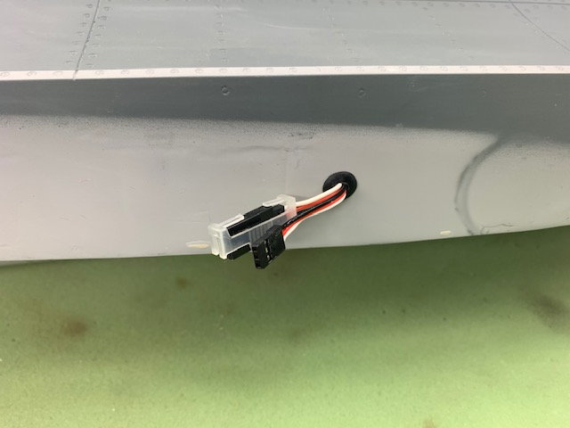
Pre wires for left wing
Pre wire for rudder
Pre wired fuse with wire sleeves glued to fuse sides
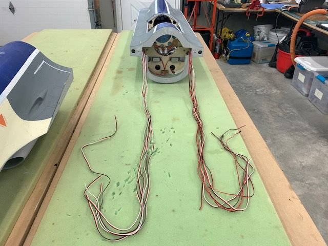
Wires from the rear fuse section. Plugs will have to be crimped on each wire. It will be fun sorting out the gear, brake, and light wires.

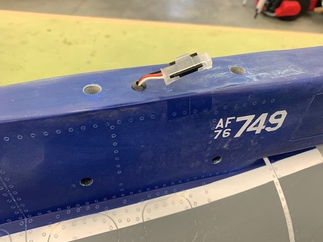
Left side wires are left wing elevons and gear, brake, and light for each main gear
Right side wires are right wing, rudder, and main gear door servos.
03-24-2021, 06:39 PM
#13

So this is were things get interesting, myself and buddy have chatted about the size of the header tank. Bigger you use the more front weight your going to have on landing since the current fuel configuration will empty the 2 60oz tanks which is either just on the CG or slightly aft, all your remaining fuel will be forward of the CG. Given that the jet is a big delta wing with lifting body it might not matter as much, but our preference is to keep as much weight out of the front which is why we are keeping the header tank at no more than 32oz.
03-24-2021, 06:44 PM
#14
Thread Starter
My Feedback: (20)
So this is were things get interesting, myself and buddy have chatted about the size of the header tank. Bigger you use the more front weight your going to have on landing since the current fuel configuration will empty the 2 60oz tanks which is either just on the CG or slightly aft, all your remaining fuel will be forward of the CG. Given that the jet is a big delta wing with lifting body it might not matter as much, but our preference is to keep as much weight out of the front which is why we are keeping the header tank at no more than 32oz. By doing that the 220 was moved aft as far as possible from the recommended location, I will have my 190 positioned in the same location just to compare.
The below picture shows you for reference the location of the 220, by doing this the nose is 0.5lbs heavy using the Xicoy CG meter which is better than expected and for now were quite happy with the result since we don't have to add additional counter weight, also is not shown in order to achieve this CG the ECU battery and JP brake controller battery are positioned on either side of that wooden rail just in front of the turbine. I'll provide you will better feedback once the 1st few flights have taken place to get a better idea on CG placement.
The below picture shows you for reference the location of the 220, by doing this the nose is 0.5lbs heavy using the Xicoy CG meter which is better than expected and for now were quite happy with the result since we don't have to add additional counter weight, also is not shown in order to achieve this CG the ECU battery and JP brake controller battery are positioned on either side of that wooden rail just in front of the turbine. I'll provide you will better feedback once the 1st few flights have taken place to get a better idea on CG placement.
F900, great info. Thanks.
Where is the CG and what do you reference it from. Is this CG info from Mike and Ali?
It sounds like everything need to be as far back as possible. I was going to use the Xicoy CG machine also for trying to set the install locations. Also I was thinking of running the tanks in series and using the front tank first, then left, then right. This leaves the landing gas in the main saddle tank. I used to do it this way alot and had no issues with lateral balance. I used parallel feed in my last 2 1/5 scale F-16s and there is always a small amount left in one of the saddle tanks.
I'll check with Mike and see what we can do about the cream paint color and decals. Thanks for the help.
Gary
03-24-2021, 07:16 PM
#15
My Feedback: (2)
Because 2 into 1 is better than 1 into 2 
I guess it's personal preference and if it turns out the CG is correct, I'm ok with landing with 0.5lbs towards the front, but the thinking is, it should not make a huge difference with a lifting body jet like this F-16XL, the lifting area is a lot bigger than it looks in the picture. Xicoy CG meter was spot on with a similar CG postion for my CARF J-10 and T-One Eurofighter. As I mentioned we will know more this weekend.
I guess it's personal preference and if it turns out the CG is correct, I'm ok with landing with 0.5lbs towards the front, but the thinking is, it should not make a huge difference with a lifting body jet like this F-16XL, the lifting area is a lot bigger than it looks in the picture. Xicoy CG meter was spot on with a similar CG postion for my CARF J-10 and T-One Eurofighter. As I mentioned we will know more this weekend.
The following users liked this post:
Auburn02 (03-24-2021)
03-25-2021, 07:54 AM
#18
So is the scheme is supposed to be the same as the one in the first pics/video on this post? How did they screw that up so bad?

The following 2 users liked this post by ravill:
drfred58809 (03-25-2021),
Viper1GJ (03-25-2021)
03-25-2021, 04:06 PM
#22
Thread Starter
My Feedback: (20)
Mike at Global Jet Club reached out to me today before I even had a chance to call about the cream color on the fuse. He is going to have the Global Knight factory send me a complete set of decals and I will repaint the cream color. I found some flat grey paint today that is pretty close and that will be a pretty easy fix if I get the decals.
Mike also sent a build guide which has answers to most of my questions about CG and control throws plus lots more.
That is great customer service and I appreciate it.
Thanks Mike and Mario ant GJC!
03-25-2021, 05:12 PM
#23
Thread Starter
My Feedback: (20)
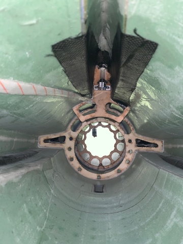
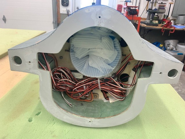
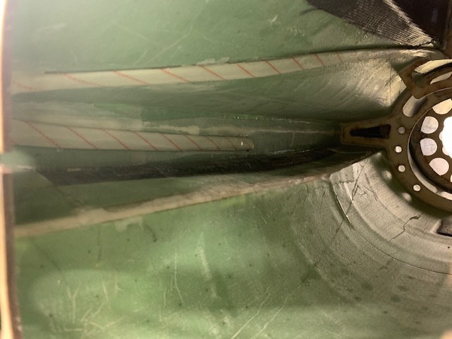
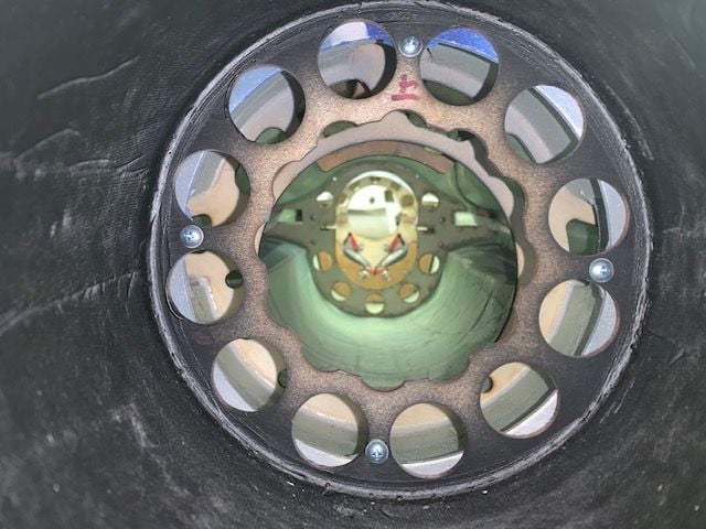
Here is the view from the pipe bell area toward the rear. Servo leads are in the striped sleeves
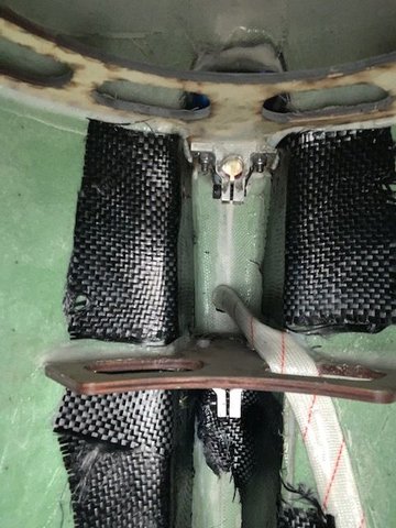
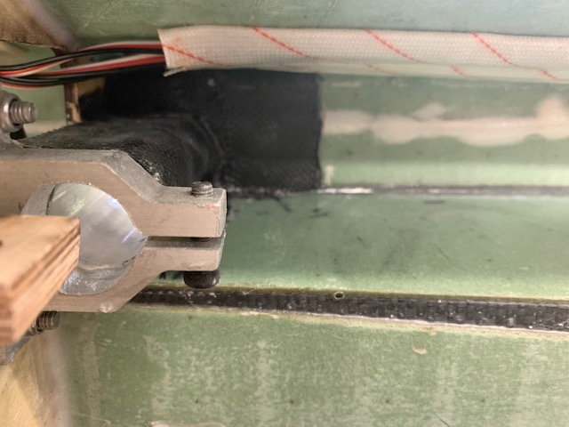
Looking up toward the vertical fin mounting brackets and rudder servo cable sleeve. Looks like carbon cloth is wrapped around the front mounting clamp.
Tail pipe ring in rear looking forward
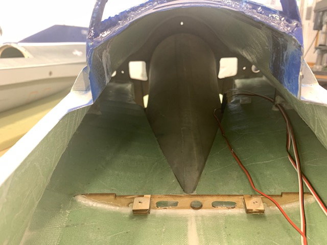
Cockpit area looking to rear. Wires are nose retract, steering and light
Nose gear well. A mini servo mounts in the lower part of the NG frame for steering. Pushrod is installed seen on the bottom frame in the photo
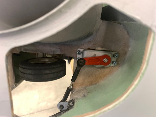
Nose gear door servo
Nose gear door
Parts table. Parts for F-105 and F-16XL intermingled here. Maybe I could make a hybrid F-105XL!
Last edited by Viper1GJ; 03-25-2021 at 05:46 PM.
03-25-2021, 05:36 PM
#24
Thread Starter
My Feedback: (20)
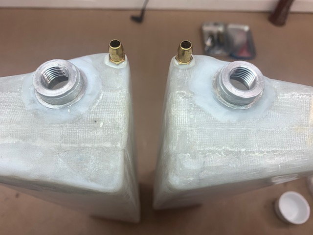
After spending half a day doing yard chores I finally got to the shop and started modifying the fuel tanks. I'm installing a "high flow" fuel system using 3/16 ID fuel lines from vent to pump.
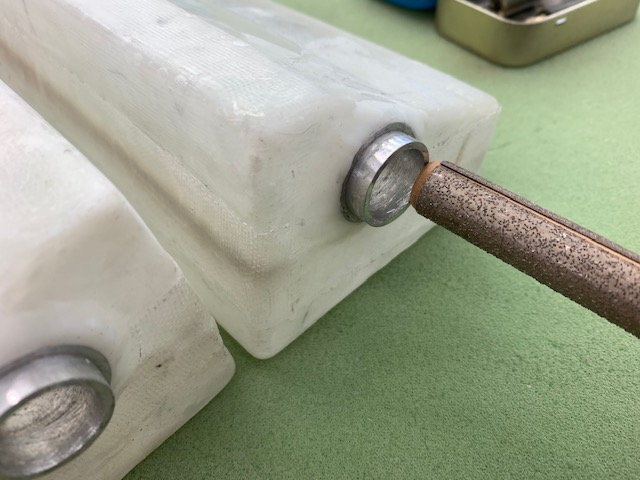
I found my fuel tank fittings fit right in the existing tank openings. I used a permagrit round file to score the inside of the tank fittings to grip the hysol epoxy.
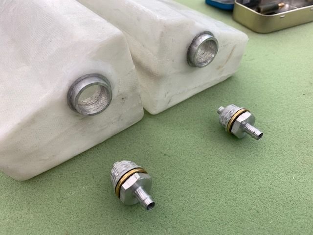
3/16" ID tank fittings with threads scuffed up.
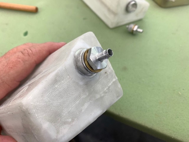
Fits like it was designed for it. I checked for clearance inside the fuse and there is plenty of room.
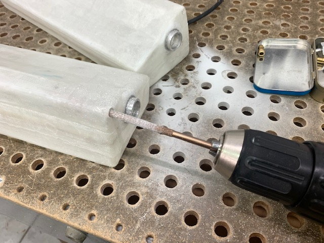
Cutting vent fitting holes with round permagrit file in drill
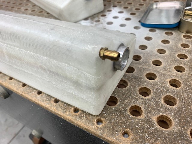
Test fit
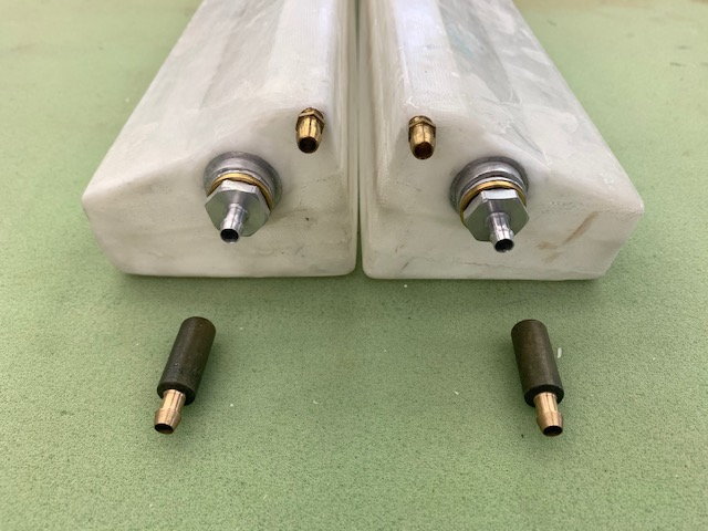
I scuffed all the mating surfaces. I inspected inside both tanks with a small mirror and they looked pretty good. I have seen some China tanks that have blobs of chinapoxy and glass fibers inside that required cutting them open to clean up the mess. These had just some shop dust plus what I put in them cutting the holes.
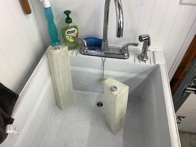
Tank rinse and volume check
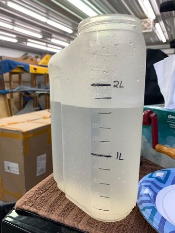
Both thank held less than 1.7 Liters. I estimated 1.68L or about 57 oz each for a total of only 116 oz. We will have to add another tank for sure to support my K-210G4.
I cleaned all the mating surfaces with acetone. Hysol was applied to both surfaces and parts inserted. Squeeze out cleaned off with Q-tips.
I found my fuel tank fittings fit right in the existing tank openings. I used a permagrit round file to score the inside of the tank fittings to grip the hysol epoxy.
3/16" ID tank fittings with threads scuffed up.
Fits like it was designed for it. I checked for clearance inside the fuse and there is plenty of room.
Cutting vent fitting holes with round permagrit file in drill
Test fit
I scuffed all the mating surfaces. I inspected inside both tanks with a small mirror and they looked pretty good. I have seen some China tanks that have blobs of chinapoxy and glass fibers inside that required cutting them open to clean up the mess. These had just some shop dust plus what I put in them cutting the holes.
Tank rinse and volume check
Both thank held less than 1.7 Liters. I estimated 1.68L or about 57 oz each for a total of only 116 oz. We will have to add another tank for sure to support my K-210G4.
I cleaned all the mating surfaces with acetone. Hysol was applied to both surfaces and parts inserted. Squeeze out cleaned off with Q-tips.
03-25-2021, 05:43 PM
#25
Thread Starter
My Feedback: (20)
Gary