


Sukhoi Su-17 M4 "Fitter", 1/6 Scale Project
 06-16-2021, 04:03 PM
#26

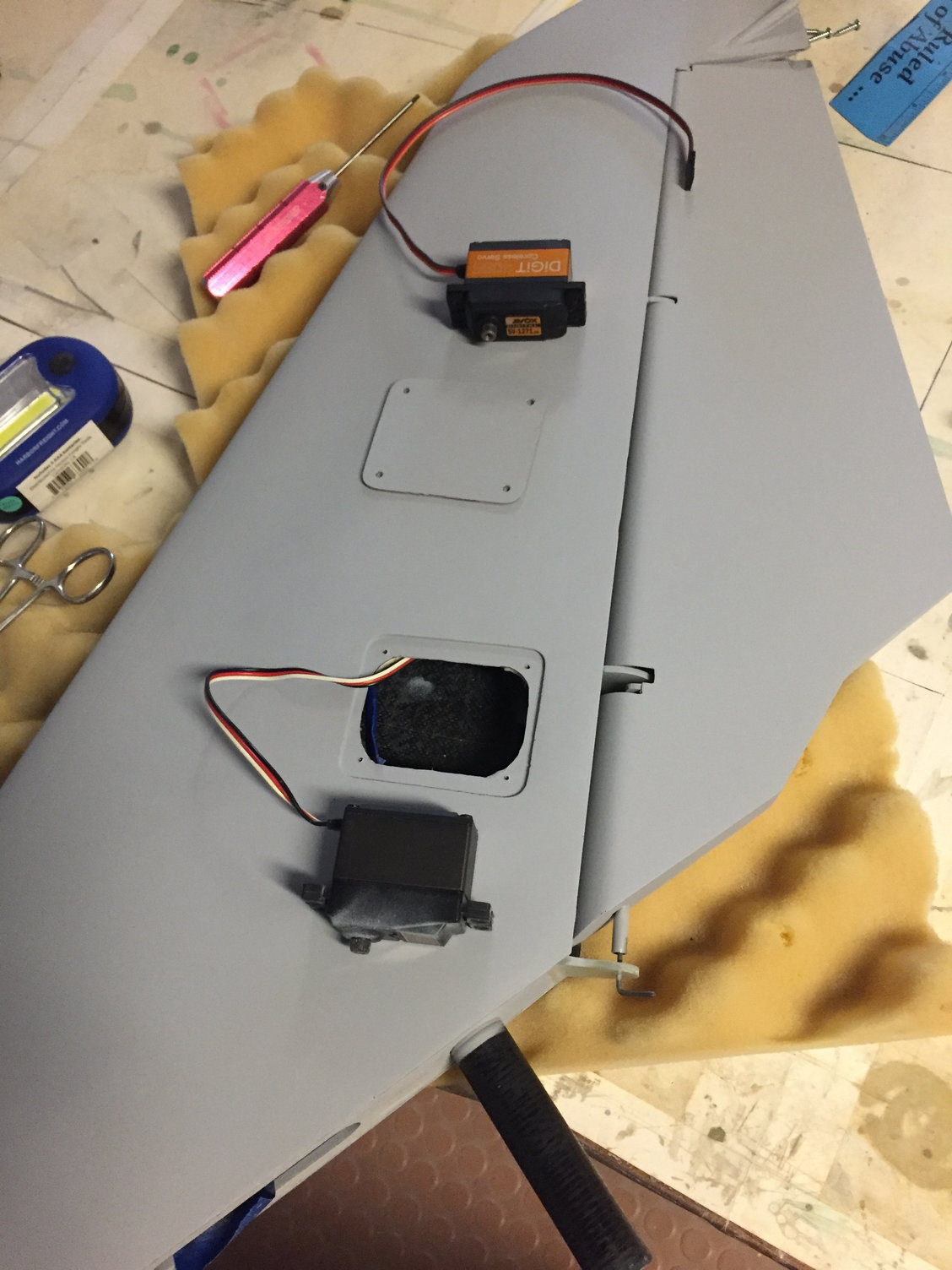
Htails went well, so time to repeat process for the Vfin and rudder. Should be easier! Intent here was to have an accessible servo and access panel located in the Vfin, but I wanted to try to use a pull pull system to operate the rudder. I don't like using torque tubes - the longer and/or smaller the diameter of the tube, the less torsional resistance you'll have to counteract the rudder loads, so greater chance of flutter. So by using threaded rods and clevises as the pull-pull hardware, one should be able to get a pretty stiff setup. There are disadvantages, with every setup. the disadvantage here, is you'll need a high torque servo, and tight linkages. Plus you can't really get any mechanical advantage with this setup , as you could with a standard control arm on the rudder. I don't wat a control horn visible.
If I would run into issues later down the road, I could pull out the pull-pull linkage, and stick a control arm and pushrod onto the external surfaces, and I'd have to then live with it. So atleast I had a plan, before installing any structure onto the Vfin skins...

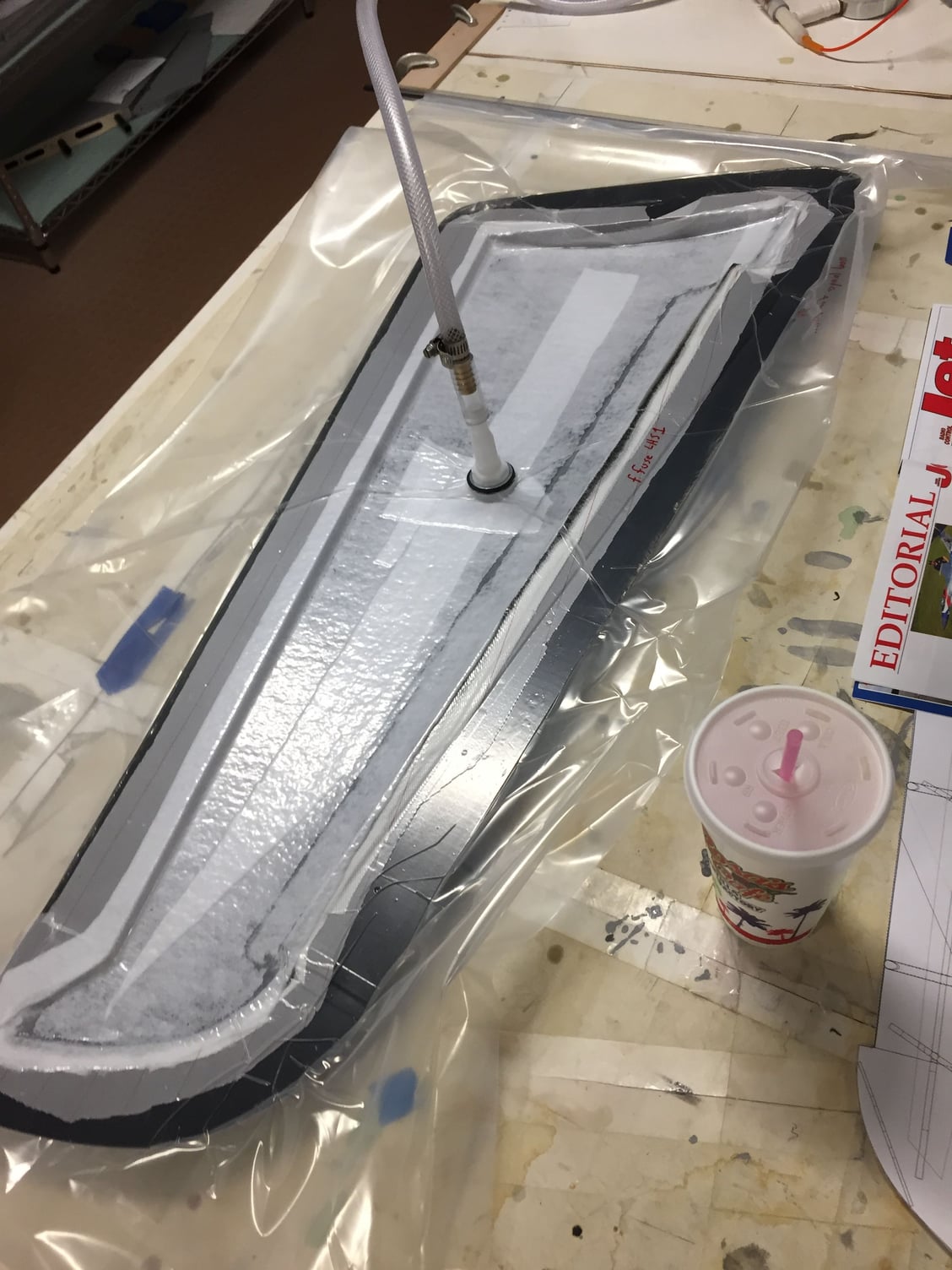
Vac bag time. Looks like I switched to using the full bag method. Much easier to maintain a vacuum. For me, any way...
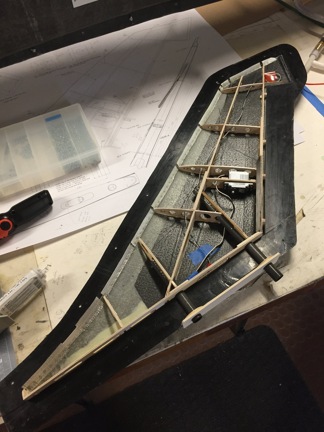
Structure, servo, and wires for lighting routed. I assumed lighting would be icing on the cake, but could likely be added after the model has flown. so for now, it's a detail...
Everything closed up in the Vfin mold. This pic is dedicated to B-1 Bob. :-D
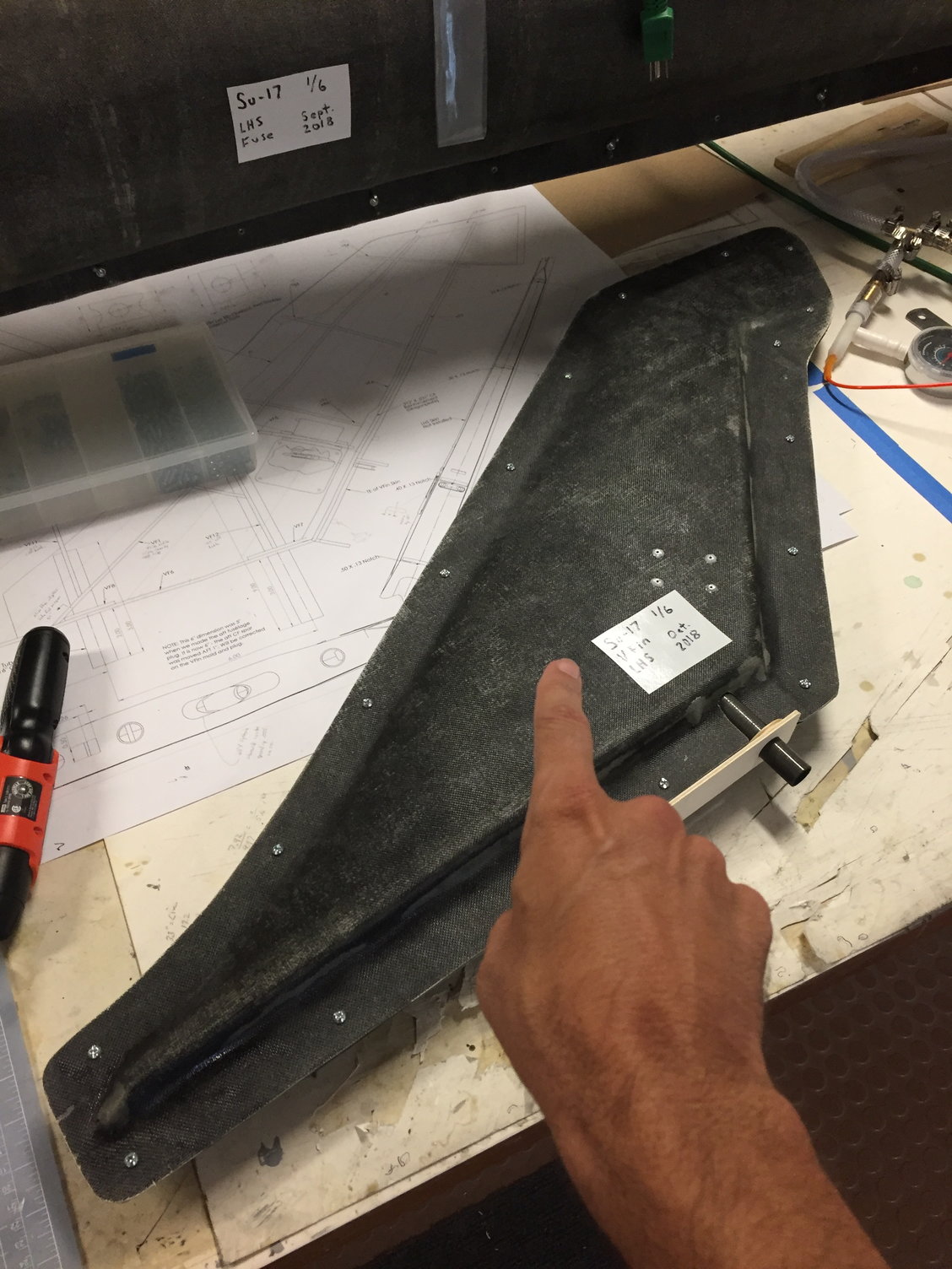
When I laid up the LH Vfin skin, I added a servo cover in the mold. When the skin is laid up and bagged, you'll be left with a skin that has a pocket for a servo cover. So that's what I have here. Also followed same process to lay up the rudder, with separate molds.
Added G-10 plates to hold a piano wire hinge, got some primer on the parts, and almost ready to throw onto the parts rack. Except after running the (approximate) loads numbers, I decided to go to a higher torque servo, and decided to run everything at 7.4 volts. So we're doing a servo swap here. Even though I'm a Futaba diehard, I decided to settle on Savox servos for just about everything in the model.
If I would run into issues later down the road, I could pull out the pull-pull linkage, and stick a control arm and pushrod onto the external surfaces, and I'd have to then live with it. So atleast I had a plan, before installing any structure onto the Vfin skins...
Vac bag time. Looks like I switched to using the full bag method. Much easier to maintain a vacuum. For me, any way...
Structure, servo, and wires for lighting routed. I assumed lighting would be icing on the cake, but could likely be added after the model has flown. so for now, it's a detail...
Everything closed up in the Vfin mold. This pic is dedicated to B-1 Bob. :-D
When I laid up the LH Vfin skin, I added a servo cover in the mold. When the skin is laid up and bagged, you'll be left with a skin that has a pocket for a servo cover. So that's what I have here. Also followed same process to lay up the rudder, with separate molds.
Added G-10 plates to hold a piano wire hinge, got some primer on the parts, and almost ready to throw onto the parts rack. Except after running the (approximate) loads numbers, I decided to go to a higher torque servo, and decided to run everything at 7.4 volts. So we're doing a servo swap here. Even though I'm a Futaba diehard, I decided to settle on Savox servos for just about everything in the model.

The following users liked this post:
grbaker (06-18-2021)
06-16-2021, 04:16 PM
#27
I could not find any pics of the final servo install for the rudder, but here is a screen shot of the cad model. The servo is basically grabbing a lower rib inside the rudder. This rib is a CF plate part. You want to maximize the separation between the pushrods, but still have a parallelogram setup between the servo, pushrods, and rudder CF plate.
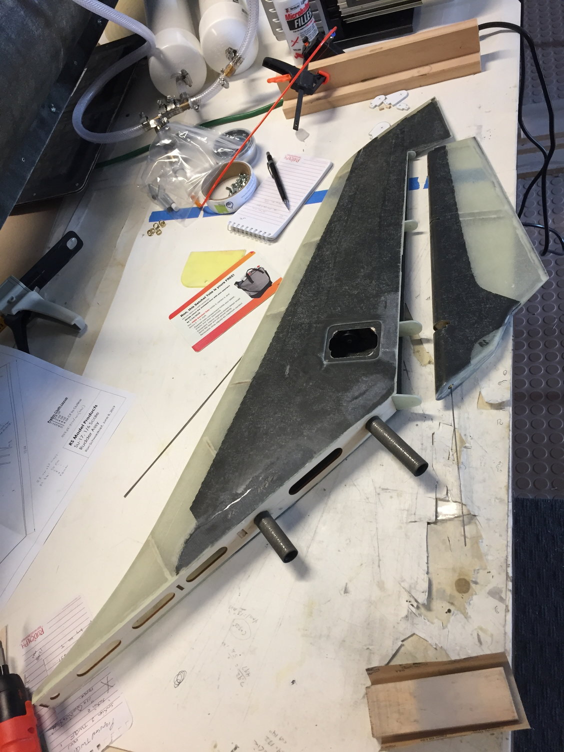
Also, you'll find you get to make a nasty cutout in the Vfin aft closeout web, for pushrod clearances... So I added additional CF material along the skins and the closeout web, to make up for the weakness brought on by the pull-pull rod cutout.
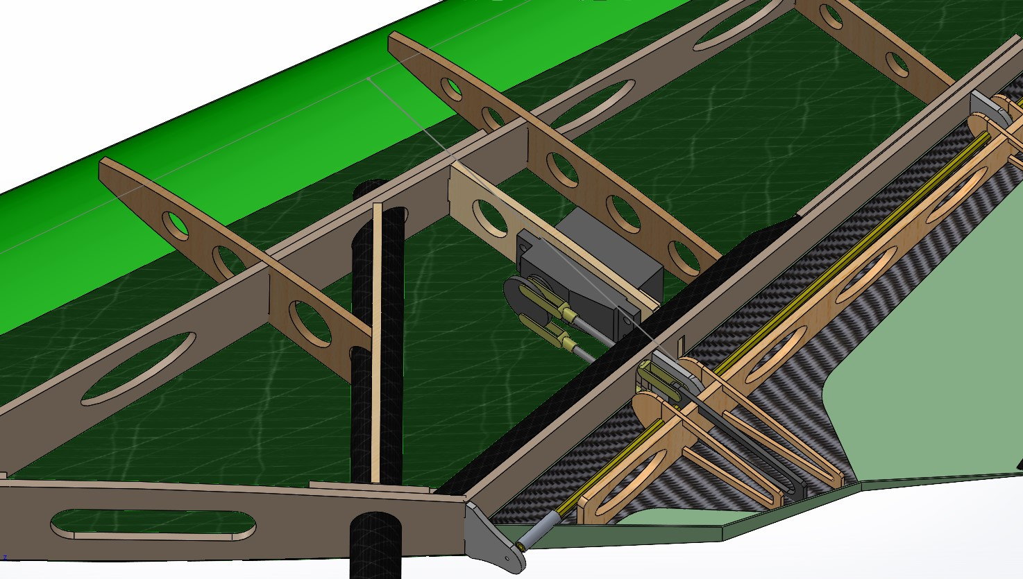
Showing pull-pull (or push-push) arrangement for the rudder/servo...
Also, you'll find you get to make a nasty cutout in the Vfin aft closeout web, for pushrod clearances... So I added additional CF material along the skins and the closeout web, to make up for the weakness brought on by the pull-pull rod cutout.
Showing pull-pull (or push-push) arrangement for the rudder/servo...
The following users liked this post:
grbaker (06-18-2021)
06-16-2021, 04:52 PM
#28
Next, is the Aft fuselage. Plan is to have it removable for accessibility, but will have to pull the tailpipe, and turbine. Similar construction method, mostly FG with CF layups where I want extra stiffness. I intend on adding operable speedbrakes, ( air system  ), and drag chute. details for the drag chute open/release have not been worked out yet, but I think I have decent workable volume for the chute and riser strings...
I can also point out that I'm wimping out on priming the molds, then doing the layups... There are advantages and disadvantages to both, I'd guess. One advantage without priming, is that one can see upon assembly, how the structure will bond with the skins if they have not been primed. Is the structure gaping with the skins? Or are you getting a good bondline, etc. One disadvantage to it, is that one may find the skins have air bubbles at the outer surface of the skin. Primer will hide them. So without priming the molds, might have to be willing to do some pinhole filling.
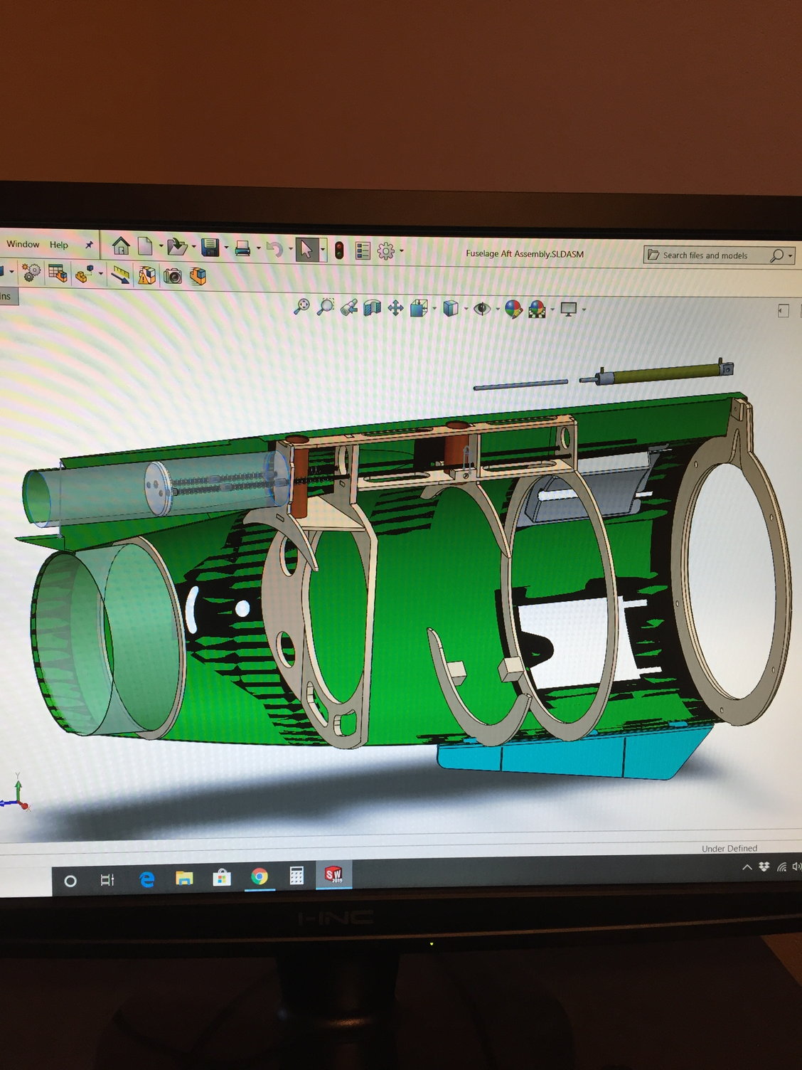
The plan. Not sure about the long air cylinder for the drag chute operation - was just doing some fitting / arrangements... Note the bulkhead that will hold the Htail pivot rods get to be angled. Great.
Plan for the speedbrake, using Robart air cylinders.
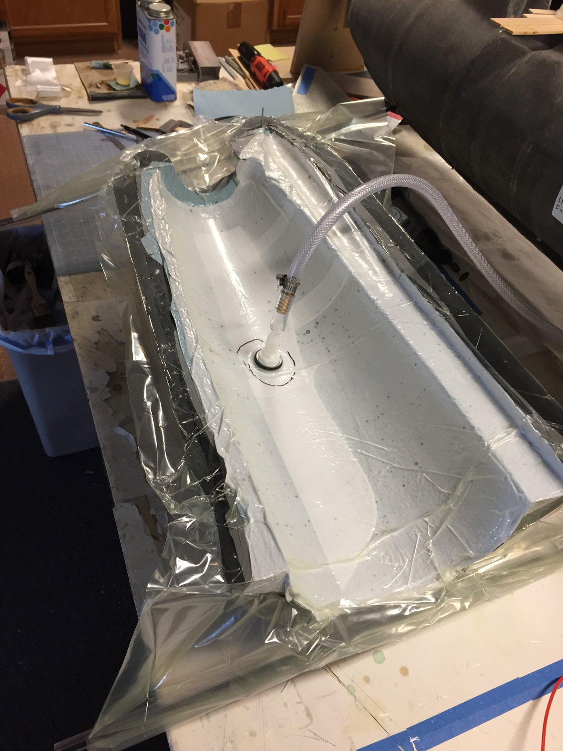
Bagging the first aft fuselage skin.
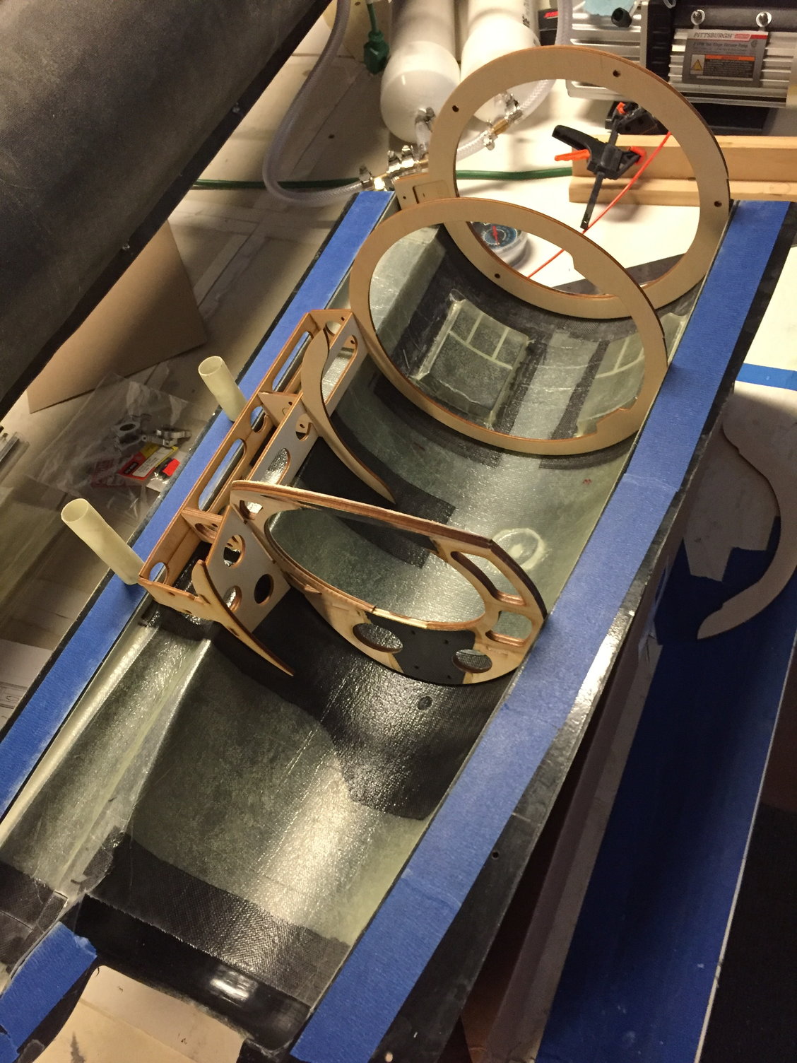
Trial fitting the Aft fuselage structure. Vfin will be removable.
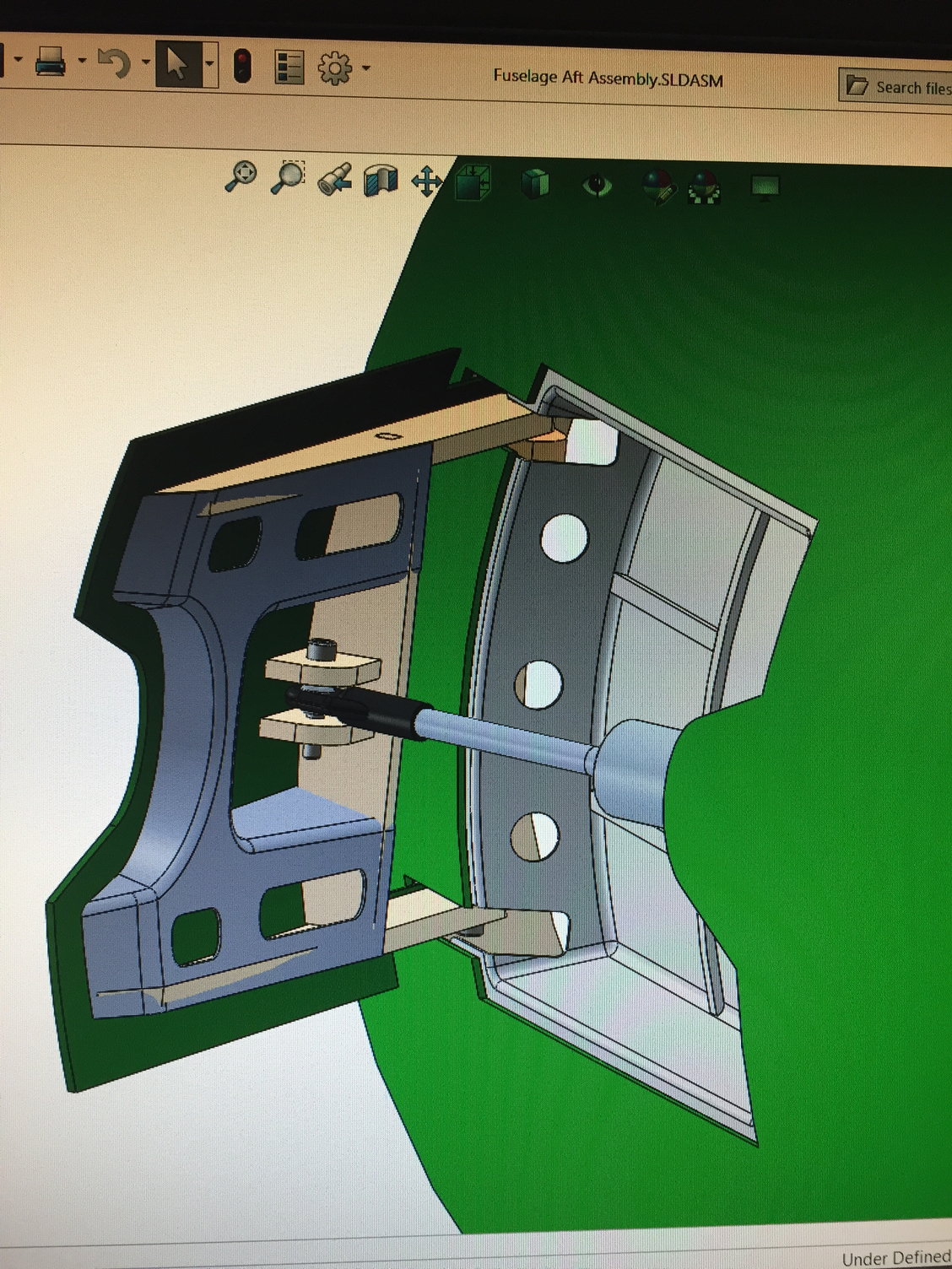
Brass tubes used to line up where the Htail pivot tubes should get rigged. Due to the swept pivot axis of the Htail, you have to deal with an Htail pushrod that swings while pivoting the Htail. Designed up a clamping arm, that will hold a heavy duty ball rod end (10-32 hardware). Perhaps overkill, but is limited to what is commercially available...
Summer 2019 aft fuselage buildup. Everything seems to fit. Time for primer on the aft fuselage, then throw this stuff onto the parts shelf.
), and drag chute. details for the drag chute open/release have not been worked out yet, but I think I have decent workable volume for the chute and riser strings...I can also point out that I'm wimping out on priming the molds, then doing the layups... There are advantages and disadvantages to both, I'd guess. One advantage without priming, is that one can see upon assembly, how the structure will bond with the skins if they have not been primed. Is the structure gaping with the skins? Or are you getting a good bondline, etc. One disadvantage to it, is that one may find the skins have air bubbles at the outer surface of the skin. Primer will hide them. So without priming the molds, might have to be willing to do some pinhole filling.
The plan. Not sure about the long air cylinder for the drag chute operation - was just doing some fitting / arrangements... Note the bulkhead that will hold the Htail pivot rods get to be angled. Great.
Plan for the speedbrake, using Robart air cylinders.
Bagging the first aft fuselage skin.
Trial fitting the Aft fuselage structure. Vfin will be removable.
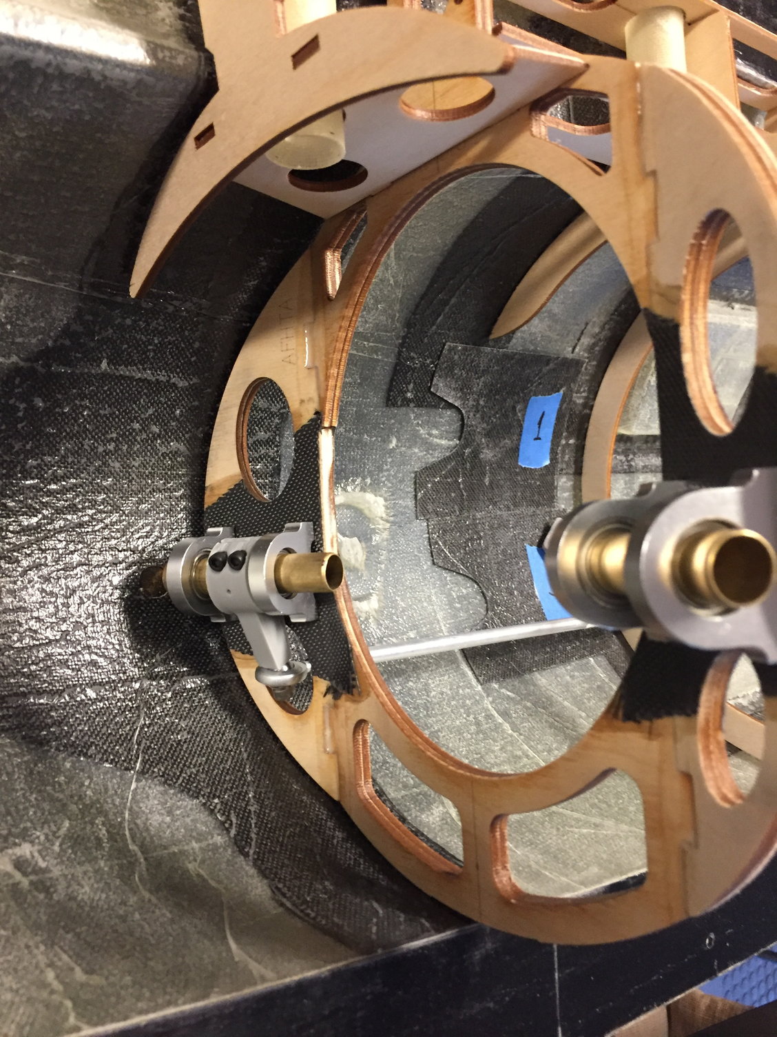
Brass tubes used to line up where the Htail pivot tubes should get rigged. Due to the swept pivot axis of the Htail, you have to deal with an Htail pushrod that swings while pivoting the Htail. Designed up a clamping arm, that will hold a heavy duty ball rod end (10-32 hardware). Perhaps overkill, but is limited to what is commercially available...
Summer 2019 aft fuselage buildup. Everything seems to fit. Time for primer on the aft fuselage, then throw this stuff onto the parts shelf.
The following users liked this post:
grbaker (06-18-2021)
06-17-2021, 07:54 AM
#29

Very cool - question, on the horizontals, you have what appears to be an anti-rotation pin protruding from the root but that obviously can't be the case given the nature of the fully pivoting stab. Or is that just a secondary spar that will be trimmed off/left short of where the stab meets the fuse?
06-17-2021, 11:05 AM
#30
The pin you pointed out is actually a lug that is grabbed on the full scale aircraft, to pivot the Htail up and down. It uses a bellcrank inside the fuselage, and so it requires a curved slot cutout in the fuselage... In my case I've modeled it as a carbon tube that works as a deflection limiter (why not?), and by adding some scale linkage looking stuff inside the cutout, one could make it appear more scale. But in reality I'm actuating the Htail by pivoting it around the Htail pivot axis with the control horn clamp I showed.
It's possible that I may not have had the slot in my model at this point. I remember making the slot small and tight, then opening it up as needed to get the deflections I wanted. Then I went back and opened the slot to make the shape either more to scale, and/or to ensure the rod does not get hung up on the slot edge.
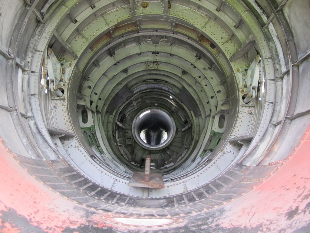
Pic of aft fuselage on full scale. Engine has been pulled out. To the L and R you can see the Htail actuation bellcranks and cylinder stuff that grab the Htail through curved slots in the fuselage.
It's possible that I may not have had the slot in my model at this point. I remember making the slot small and tight, then opening it up as needed to get the deflections I wanted. Then I went back and opened the slot to make the shape either more to scale, and/or to ensure the rod does not get hung up on the slot edge.
Pic of aft fuselage on full scale. Engine has been pulled out. To the L and R you can see the Htail actuation bellcranks and cylinder stuff that grab the Htail through curved slots in the fuselage.
Last edited by Ron S; 06-17-2021 at 11:10 AM. Reason: added slot text
06-17-2021, 11:23 AM
#31
Around August 2019 I worked on some of the smaller parts, such as wing control surfaces, and hatches on the fuselage. Here are a few pics of some of that.
Aileron skins and structure being rigged in place before closing up.
Same with the outboard TE Flaps.
And Inbd TE Flaps. Missing a couple ribs here.
Engine hatch getting a mid length bulkhead
And by Nov 2019, canopy and aft cockpit hatches have been removed from the molds.
Aileron skins and structure being rigged in place before closing up.
Same with the outboard TE Flaps.
And Inbd TE Flaps. Missing a couple ribs here.
Engine hatch getting a mid length bulkhead
And by Nov 2019, canopy and aft cockpit hatches have been removed from the molds.
The following users liked this post:
grbaker (06-18-2021)
06-17-2021, 11:32 AM
#32
Forward fuselage also began in this timeframe.
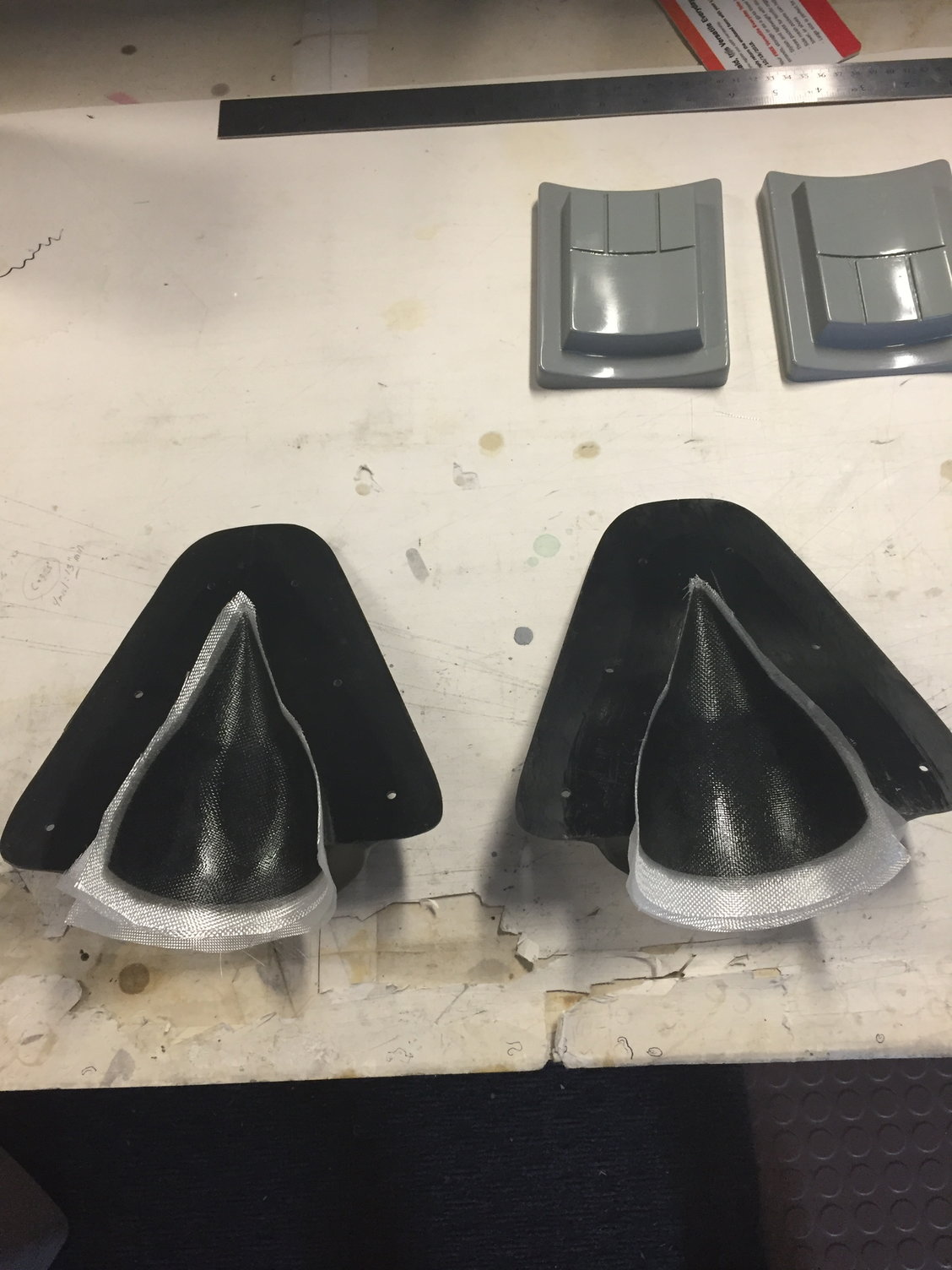
Inlet Shock Cones being laid up in the molds.
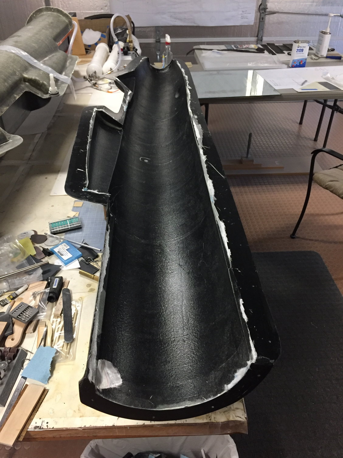
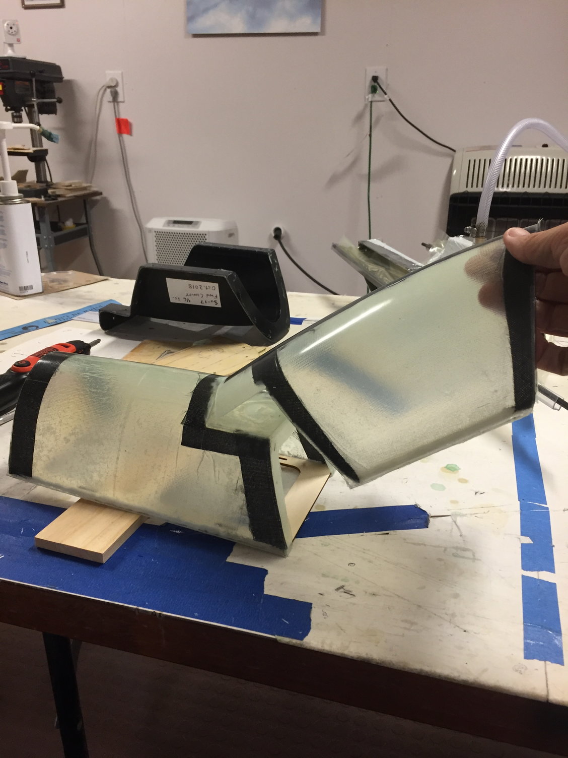
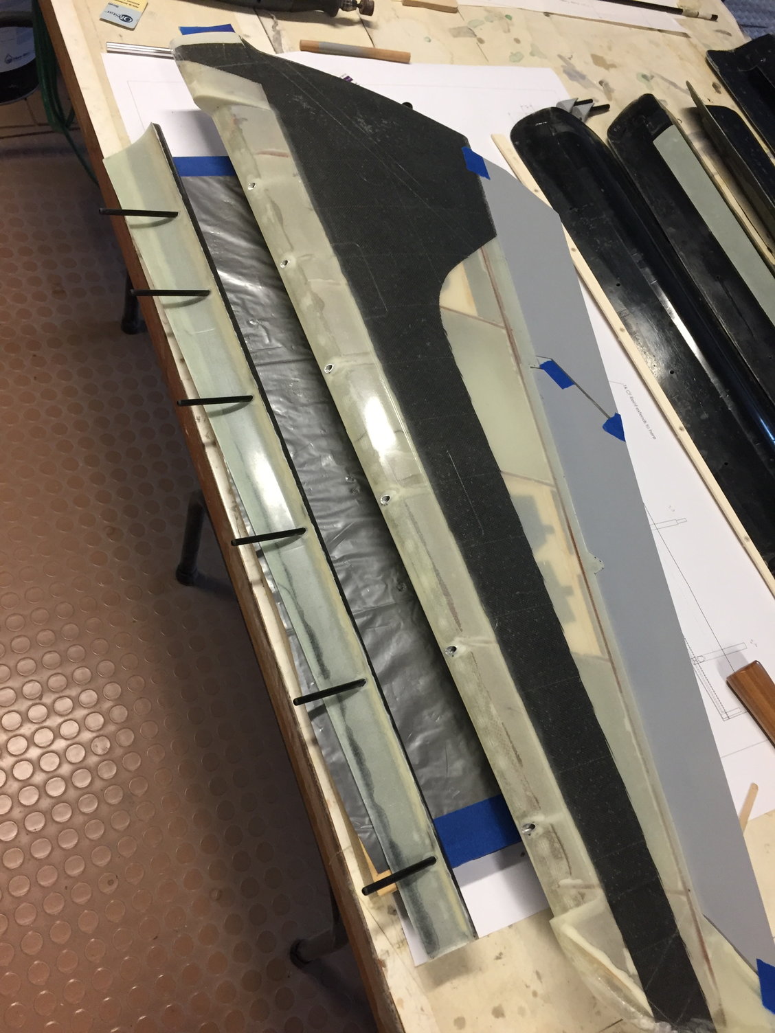
One of the fuselage skins debagged... these were long parts (relative to my not-too-indepth experience), and made for long days laying them up.
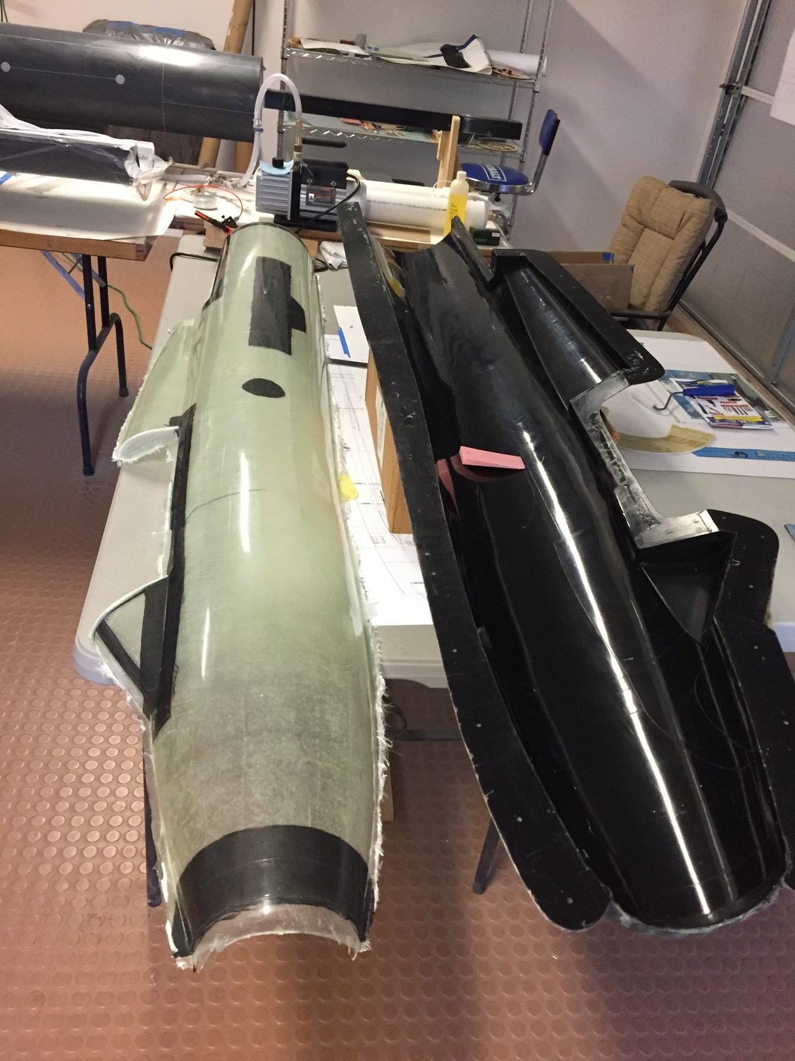
One of the skins out of the mold. Green tint of the glass is the PVA needing to be washed off.
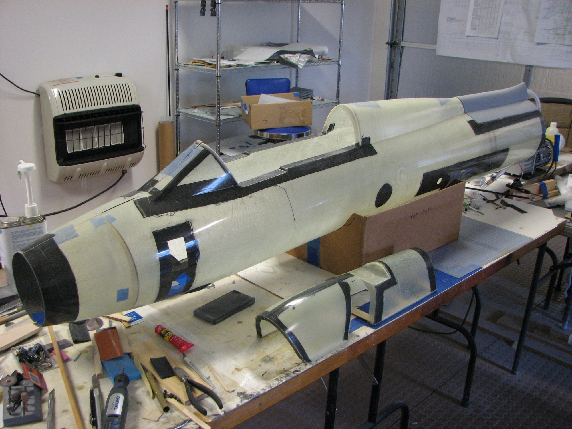
Skins being trimmed and trial fitted before going back into the molds to be seamed together.
Inlet Shock Cones being laid up in the molds.
One of the fuselage skins debagged... these were long parts (relative to my not-too-indepth experience), and made for long days laying them up.
One of the skins out of the mold. Green tint of the glass is the PVA needing to be washed off.
Skins being trimmed and trial fitted before going back into the molds to be seamed together.
Last edited by Ron S; 06-17-2021 at 11:34 AM. Reason: added pic
The following users liked this post:
grbaker (06-18-2021)
06-17-2021, 12:23 PM
#33
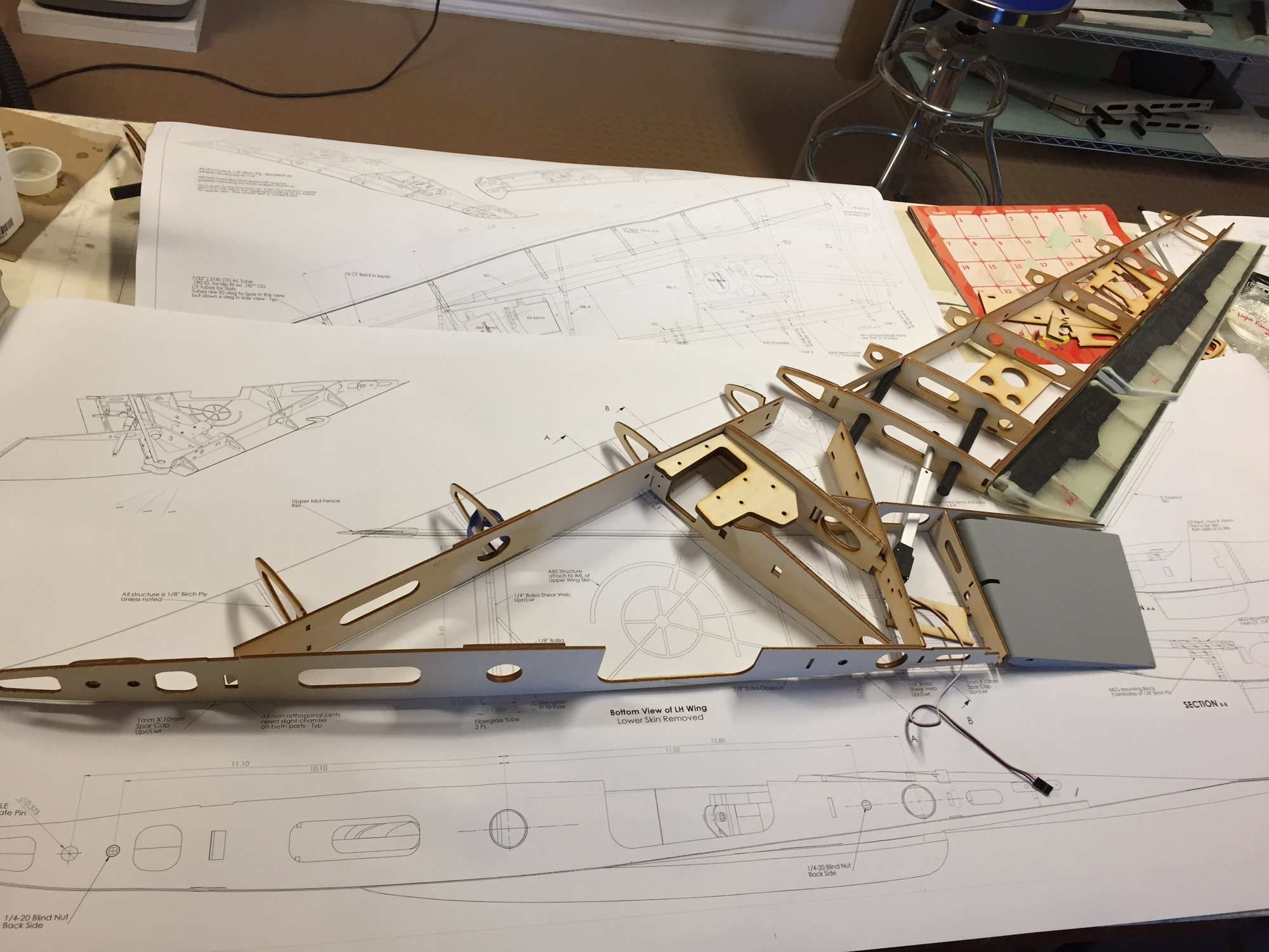
Around March 2020, I was finally bagging the inboard wing skins. The forward fuselage was not final finished, because at some point I was going to need to rig the inboard wings with the fuselage. I wanted to have the inboard wings available to rig properly to the fuselage, and to locate the fuselage bulkheads that will hold the wing spar tubes.
The wing mounts to the fuselage using two CF tubes - same diameter, but the largest diameter I could fit inside the wing. The aftmost tube takes the majority of the bending load. If I run into load issues or I want to be more conservative with bending loads, I can add another CF tube inside the aft CF wing spar tube. Below shows the intended internal arrangement for the Inboard Wing. The wing mounts to the fuselage with 1 degree of incidence, and 3 degrees of anhedral - which means one cannot run the tubes continuously from the LH panel, thru the fuselage, to the RH panel. Oh well. I will set up the parts so that I can remove the CF tubes if needed (ie, sleeved in the fuselage and also in the wing.) One could possibly save an ounce or two if they were permanently installed in the wing. One could also make the inboard wings part of the center fuselage, and I'm certain several ounces of weight could be saved. That would mean a more complex, larger plug/mold, and I would have difficulty in dealing with that.
The plan also, is to have the Outboard wing panels (the part that swings fwd/aft) SIMPLY plug into a swinging arm - the arm attaches to the pivot mechanism, and is yawed by a linear actuator aft of the MLG. The area near the MLG and pivot gets pretty busy, quick. On the real aircraft, the location of the pivot point was dictated by the location of a major hardpoint on the Su-7. The fixed wing Su-7, essentially, had the outer wing removed, the hardpoint (where major structural members ran to) was converted over to a pivot point, then the outboard wing attached - this is a very simplified way of describing it.
This pivot design is somewhat similar to the Skymaster F-14. I'm not sure what they used for materials for their pivot arm, but it was not Aluminum. And I'm not sure what they are using for the actual pivot hardware (regarding pins/bearings), but for my prototype, it is 7075T6, and hence it is a chunky piece of material. We'll see how this works for the prototype. I'm using a 5/8" dia steel tube for the Pivot Pin, with an Aluminum filler inside. I have an upper and lower carbon plate mounted to the main wood spars - these carbon plate holds the pin fixed. Between the plates is the Aluminum arm. And between the Aluminum arm and the Pivot Pin, are tapered roller bearings, so I can transfer vertical, side, and moment loads from the outboard wings to the Inboard wing structure. A big bolt goes thru all of it, to clamp the sandwich of parts together, and to minimize slop of the whole thing.
Maybe I could have gotten away with bushings - I'm not sure. But we're building a prototype. Onward!
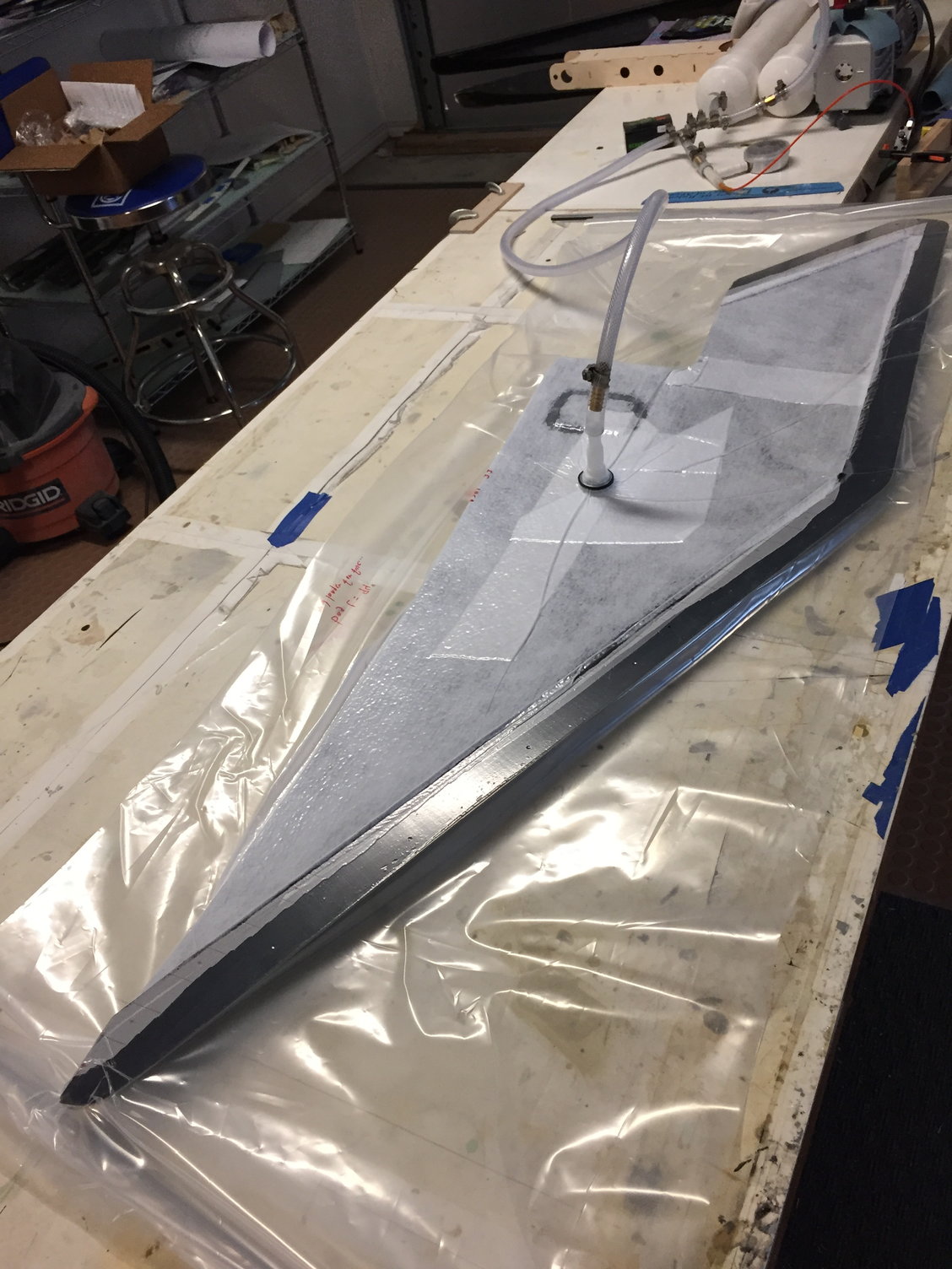
Bagging the Inboard wing skins.
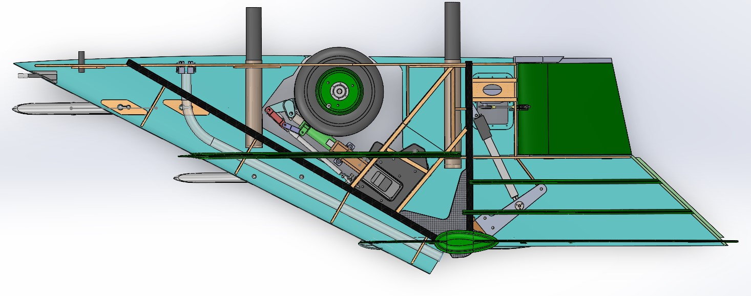
Plan view of the internal layout of the inboard wing. Linear actuator and Swing arm can be seen.
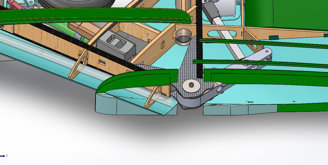
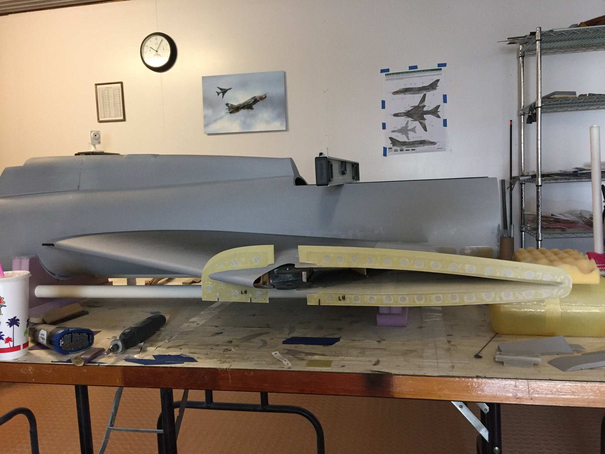
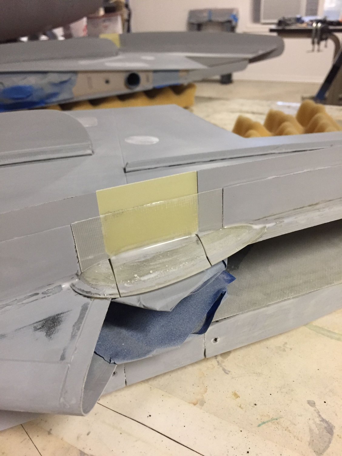
Closer view of the Pivot Area - green teardrop shaped Upper Pivot Cover removed. There is a wing fence/pylon pretty much at the same station as the pivot point. Great...
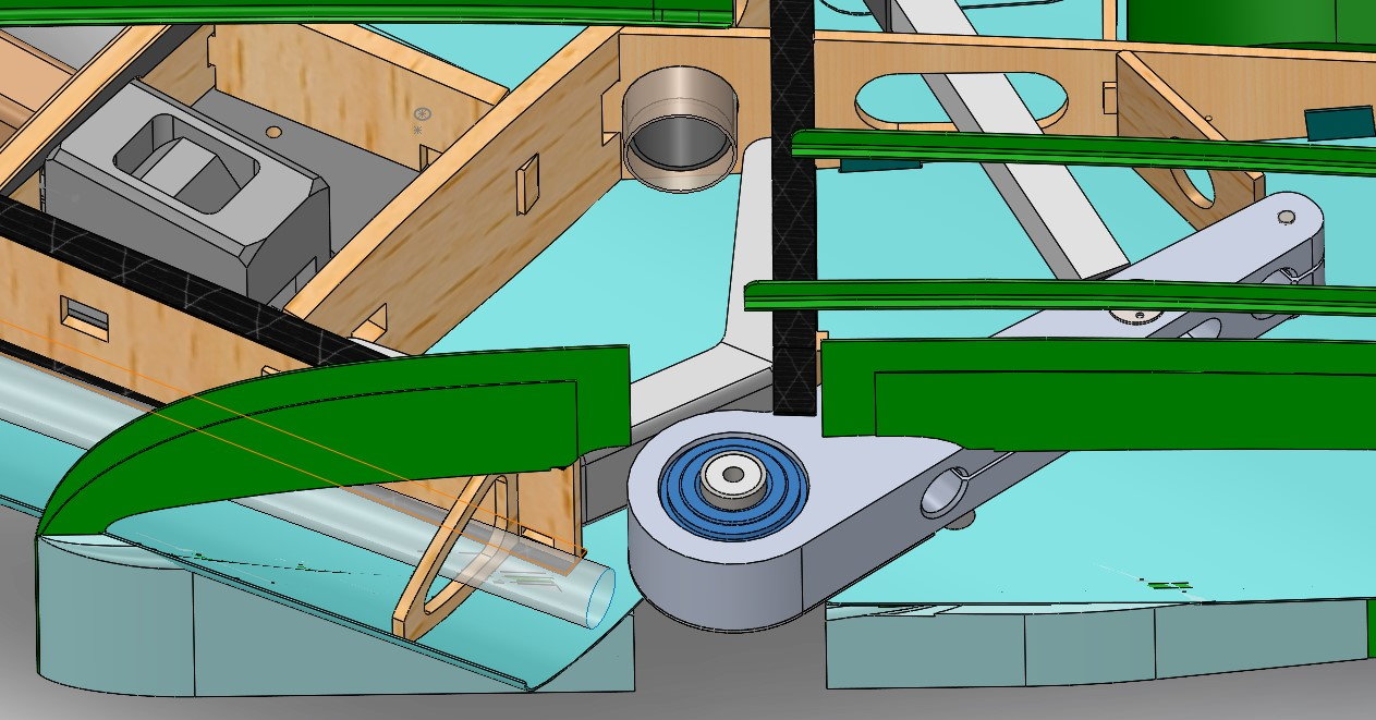
Carbon plates that hold the pin - removed. The pin is visible, along with the taper bearings (blue).
The wing mounts to the fuselage using two CF tubes - same diameter, but the largest diameter I could fit inside the wing. The aftmost tube takes the majority of the bending load. If I run into load issues or I want to be more conservative with bending loads, I can add another CF tube inside the aft CF wing spar tube. Below shows the intended internal arrangement for the Inboard Wing. The wing mounts to the fuselage with 1 degree of incidence, and 3 degrees of anhedral - which means one cannot run the tubes continuously from the LH panel, thru the fuselage, to the RH panel. Oh well. I will set up the parts so that I can remove the CF tubes if needed (ie, sleeved in the fuselage and also in the wing.) One could possibly save an ounce or two if they were permanently installed in the wing. One could also make the inboard wings part of the center fuselage, and I'm certain several ounces of weight could be saved. That would mean a more complex, larger plug/mold, and I would have difficulty in dealing with that.
The plan also, is to have the Outboard wing panels (the part that swings fwd/aft) SIMPLY plug into a swinging arm - the arm attaches to the pivot mechanism, and is yawed by a linear actuator aft of the MLG. The area near the MLG and pivot gets pretty busy, quick. On the real aircraft, the location of the pivot point was dictated by the location of a major hardpoint on the Su-7. The fixed wing Su-7, essentially, had the outer wing removed, the hardpoint (where major structural members ran to) was converted over to a pivot point, then the outboard wing attached - this is a very simplified way of describing it.
This pivot design is somewhat similar to the Skymaster F-14. I'm not sure what they used for materials for their pivot arm, but it was not Aluminum. And I'm not sure what they are using for the actual pivot hardware (regarding pins/bearings), but for my prototype, it is 7075T6, and hence it is a chunky piece of material. We'll see how this works for the prototype. I'm using a 5/8" dia steel tube for the Pivot Pin, with an Aluminum filler inside. I have an upper and lower carbon plate mounted to the main wood spars - these carbon plate holds the pin fixed. Between the plates is the Aluminum arm. And between the Aluminum arm and the Pivot Pin, are tapered roller bearings, so I can transfer vertical, side, and moment loads from the outboard wings to the Inboard wing structure. A big bolt goes thru all of it, to clamp the sandwich of parts together, and to minimize slop of the whole thing.
Maybe I could have gotten away with bushings - I'm not sure. But we're building a prototype.
Onward!Bagging the Inboard wing skins.
Plan view of the internal layout of the inboard wing. Linear actuator and Swing arm can be seen.
Closer view of the Pivot Area - green teardrop shaped Upper Pivot Cover removed. There is a wing fence/pylon pretty much at the same station as the pivot point. Great...
Carbon plates that hold the pin - removed. The pin is visible, along with the taper bearings (blue).
The following users liked this post:
grbaker (06-18-2021)
06-17-2021, 12:36 PM
#34
And pics of some of the final hardware being assembled, for the Inboard wing...
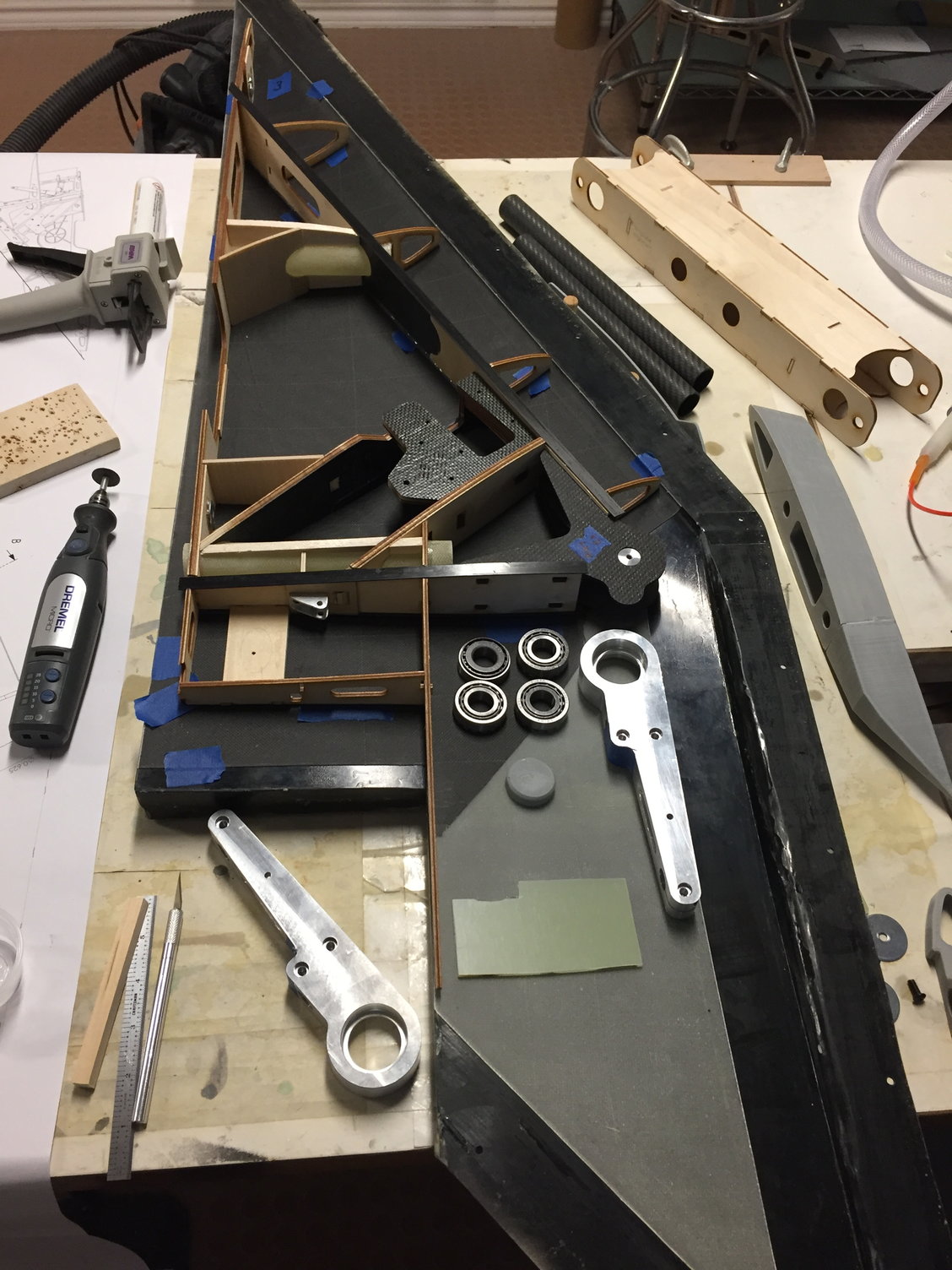
View of Lower LH Inboard wing - hardware being rigged in place...
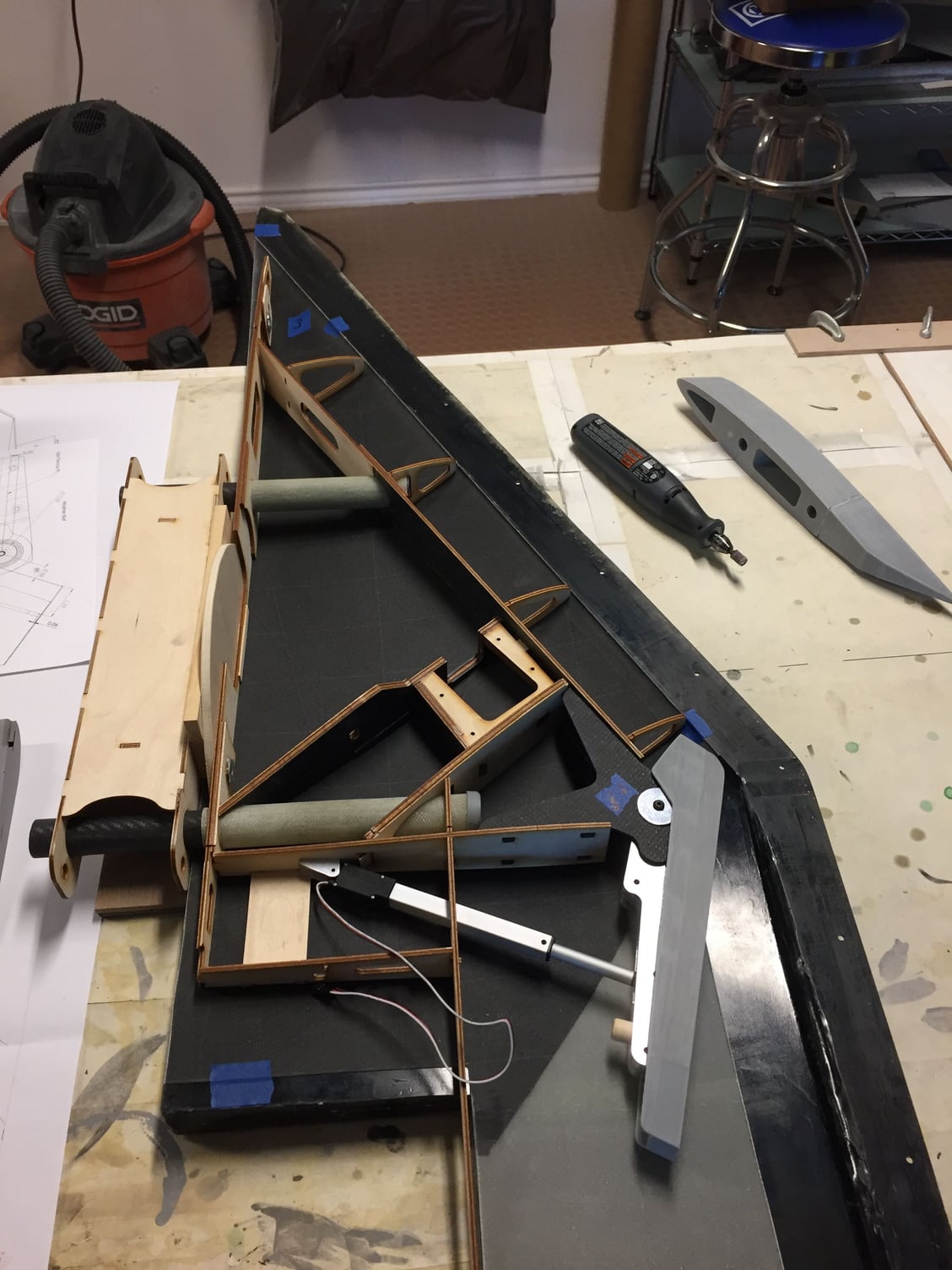
Pic showing where the Linear Actuator will reside.
Structure bonded to the upper skin already. Getting ready to bond LH Lower skin to the assembly, then close up in the molds. There is a gray ABS spacer mounted to the pivot arm to ensure proper clearance with the wingskins.
View of Lower LH Inboard wing - hardware being rigged in place...
Pic showing where the Linear Actuator will reside.
Structure bonded to the upper skin already. Getting ready to bond LH Lower skin to the assembly, then close up in the molds. There is a gray ABS spacer mounted to the pivot arm to ensure proper clearance with the wingskins.
The following users liked this post:
grbaker (06-18-2021)

 06-18-2021, 02:46 PM
#38
Thank you, George! 
Next is the Outboard wing. These panels will have LE Slats, Ailerons, and outbd TE Flaps. The intent is to use 2 small servos to, in parallel, push the Slat out. The Slat truly should slide out at a slight curve - curving downward as it travels forward (and down). I believe Slats work by energizing the air near the top side of the airfoil (due to the slot that is created from the lower side of the airfoil to the upper side). Since the LE moves down as it deploys forward, it is also effecting the camber of the wing. Generally, adding camber to a wing, should create more lift than a symmetrical airfoil at the same angle of attack.
I was concerned about making reliably moving Slats with 6 curved rails, at this model's small scale. I also wanted to make a single slat - on the real aircraft, the Slats appear to be broken up into 3 segments, but I believe they are actuated mechanically (I think they are not gravity operated like an A-4 Skyhawk, etc)... So I decided to have the Slats deploy forward, but also down (linearly) at a 6 degree angle (I think I remember it as 6 degrees down!) downward. That way, if the slot that is created between the (back side of the) Slat itself and the rest of the wing does not create a correct or effective slot, atleast I should get a camber effect. And that should allow for the inboard wing to stall a bit sooner than the outboard wing. So I'm hoping/expecting there should be some benefit. (Is it worth the weight and complexity? I can't say, but I'll say the challenge is worth it. So I will march on. )
The Outboard TE Flap appears to only be deflected down (around 25 degrees) during landings. I decided I would put the slats and Outboard TE Flaps on a 3 position switch. I also decided these would only be operated when the wing is in the Full Forward position. (If not, the TE Flap will strike the inbd wing - not good.) The 3 position switch will correspond to: 1- Clean Outboard Wing, 2- Slat part out and TE Flap part out (for takeoff), and 3 - Full Slat out and Outboard TE Flap full down 25 degrees. If we survive first flight, we can tweak the settings from there.
So I'll show pics of the structural plan of the Outboard wing, how it mates to the Inboard wing, and maybe some Slat cross sections.
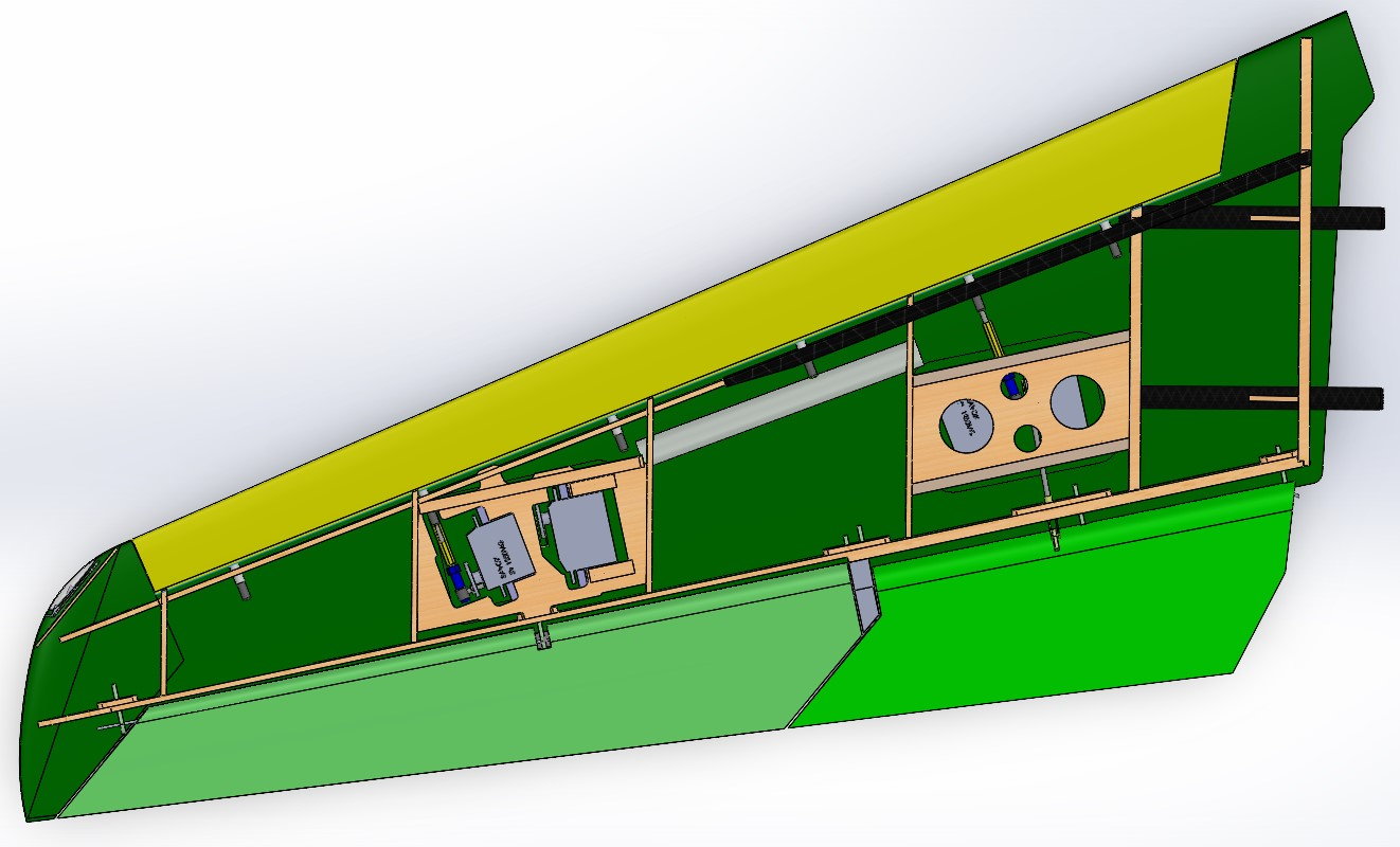
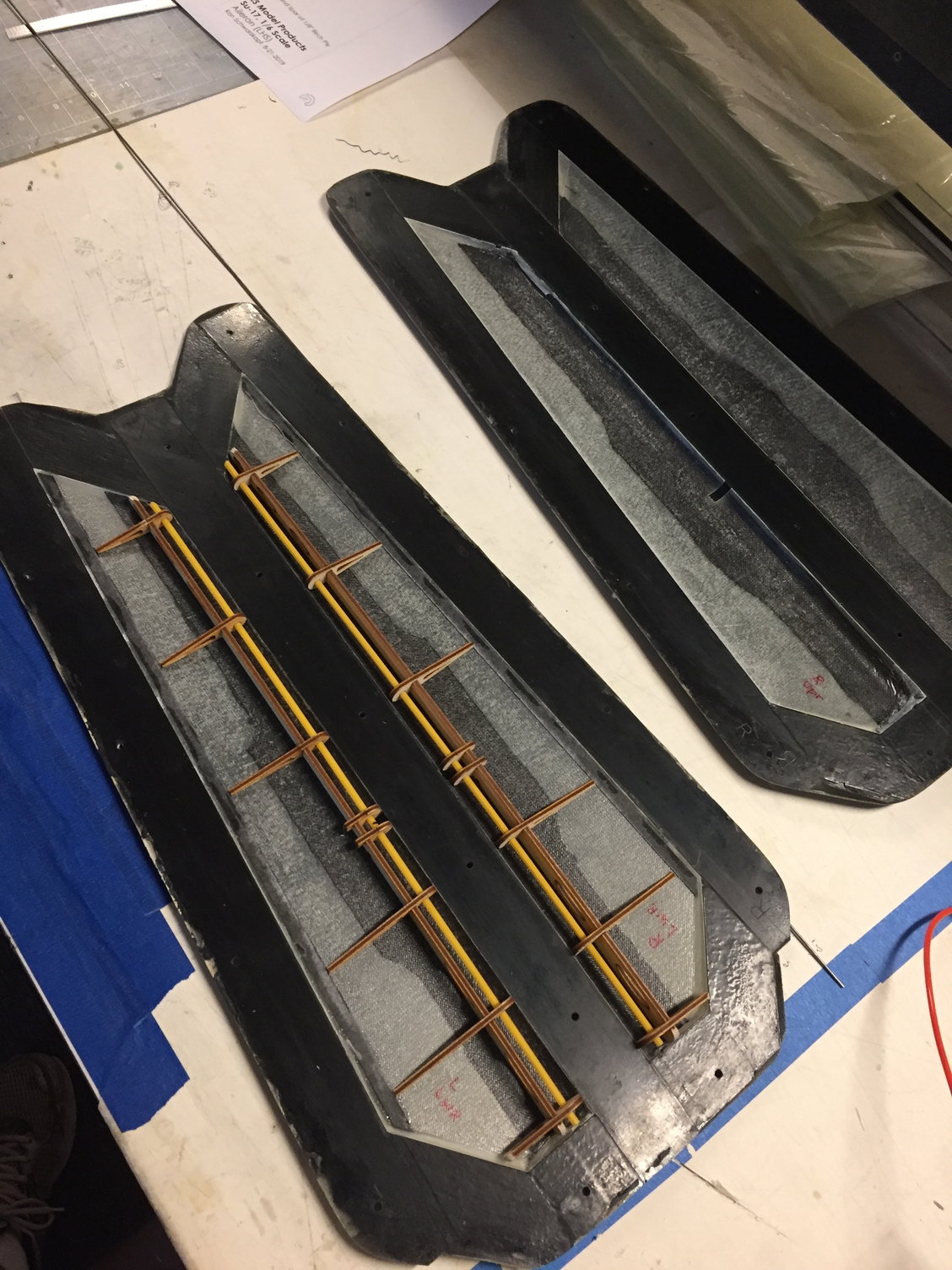
Outboard wing panel (LH side), with the wing upper FG skin removed. Basic setup with a Fwd spar, and a TE closeout spar. servos accessible thru 2 lower covers. Inbd portion of this panel has 2 carbon rods, to pass the load from the Outboard wing to the Aluminum sweep arm on the Inboard wing.
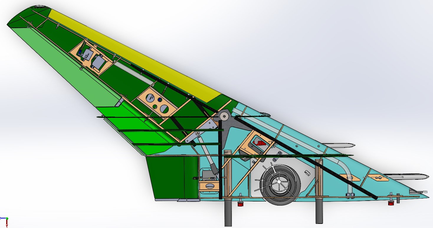
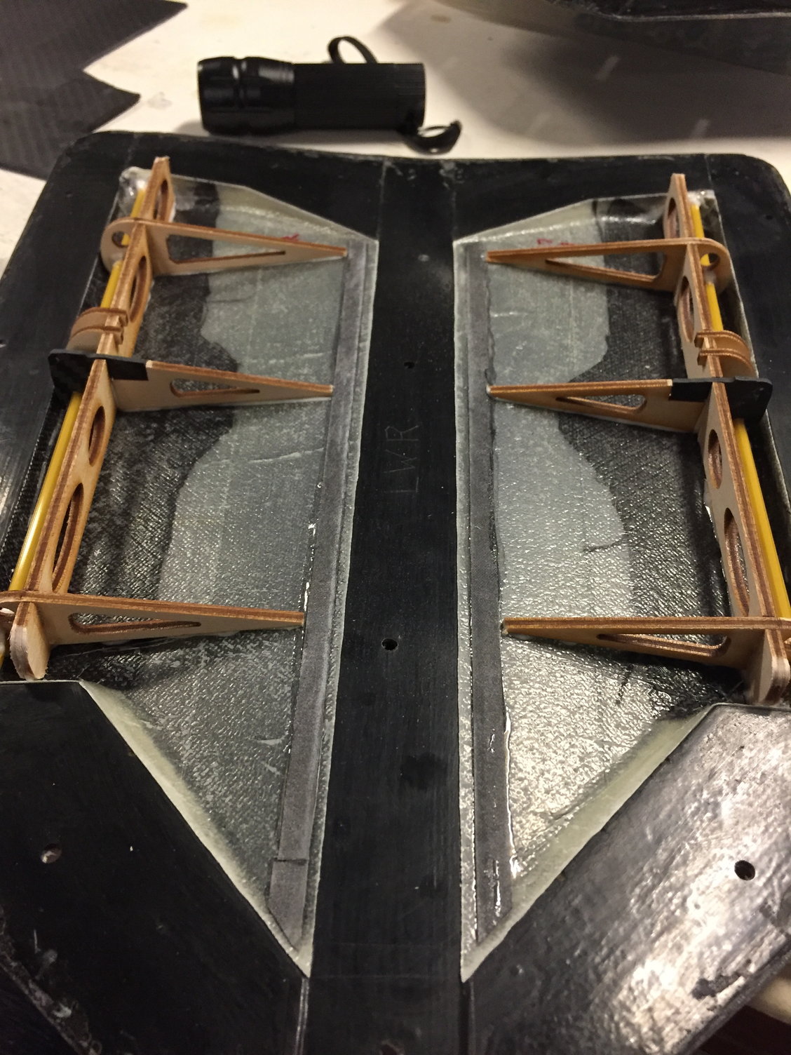
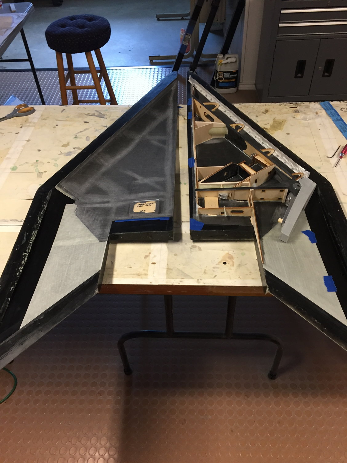
Outboard wing mated to the Inboard wing, with both upper wing skins removed so you can see some of the load path. The carbon rods of the Outboard wing are clamped to the Aluminum swing arm by 3 clamping screws accessed on the bottom side of the inboard wing. Wing is shown in the full swept aft position. Note the majority of the Outboard TE Flap is now buried inside the Inboard Wing TE.
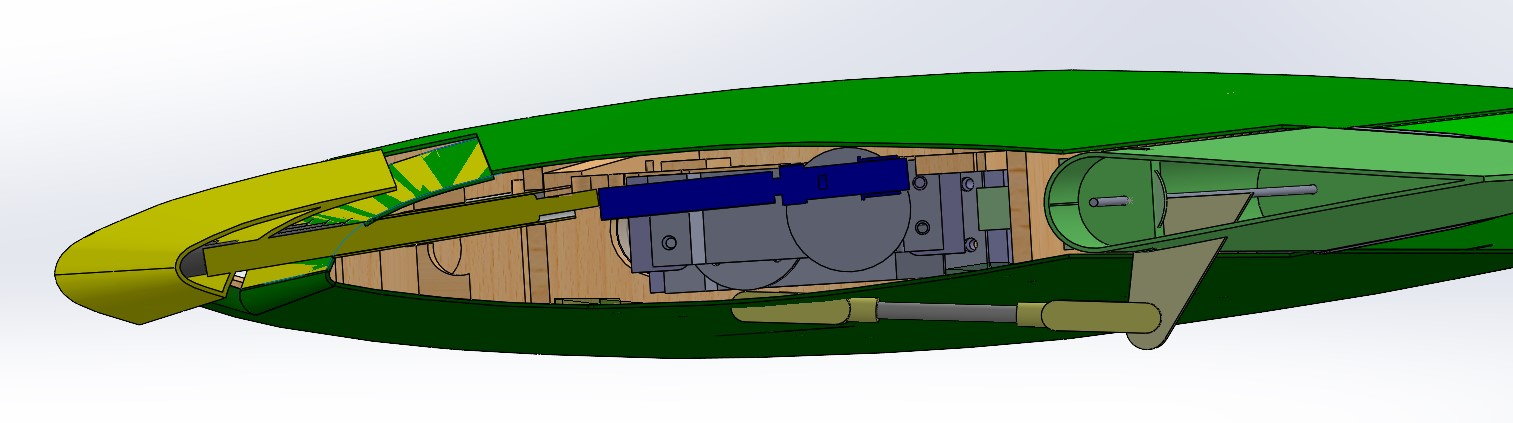
Might be hard to decode this, but this is a cross section of the wing at the outboard slat servo. You see the servo, the servo yellow/blue pushrod going forward, the yellow Slat and "track" going 6 degrees down, and you can kinda see the slot created between the back side of the slat and the green wingskin. toward the right of the pic you see a cross section of the Aileron.
Next is the Outboard wing. These panels will have LE Slats, Ailerons, and outbd TE Flaps. The intent is to use 2 small servos to, in parallel, push the Slat out. The Slat truly should slide out at a slight curve - curving downward as it travels forward (and down). I believe Slats work by energizing the air near the top side of the airfoil (due to the slot that is created from the lower side of the airfoil to the upper side). Since the LE moves down as it deploys forward, it is also effecting the camber of the wing. Generally, adding camber to a wing, should create more lift than a symmetrical airfoil at the same angle of attack.
I was concerned about making reliably moving Slats with 6 curved rails, at this model's small scale. I also wanted to make a single slat - on the real aircraft, the Slats appear to be broken up into 3 segments, but I believe they are actuated mechanically (I think they are not gravity operated like an A-4 Skyhawk, etc)... So I decided to have the Slats deploy forward, but also down (linearly) at a 6 degree angle (I think I remember it as 6 degrees down!) downward. That way, if the slot that is created between the (back side of the) Slat itself and the rest of the wing does not create a correct or effective slot, atleast I should get a camber effect. And that should allow for the inboard wing to stall a bit sooner than the outboard wing. So I'm hoping/expecting there should be some benefit. (Is it worth the weight and complexity? I can't say, but I'll say the challenge is worth it. So I will march on.
)The Outboard TE Flap appears to only be deflected down (around 25 degrees) during landings. I decided I would put the slats and Outboard TE Flaps on a 3 position switch. I also decided these would only be operated when the wing is in the Full Forward position. (If not, the TE Flap will strike the inbd wing - not good.) The 3 position switch will correspond to: 1- Clean Outboard Wing, 2- Slat part out and TE Flap part out (for takeoff), and 3 - Full Slat out and Outboard TE Flap full down 25 degrees. If we survive first flight, we can tweak the settings from there.
So I'll show pics of the structural plan of the Outboard wing, how it mates to the Inboard wing, and maybe some Slat cross sections.
Outboard wing panel (LH side), with the wing upper FG skin removed. Basic setup with a Fwd spar, and a TE closeout spar. servos accessible thru 2 lower covers. Inbd portion of this panel has 2 carbon rods, to pass the load from the Outboard wing to the Aluminum sweep arm on the Inboard wing.
Outboard wing mated to the Inboard wing, with both upper wing skins removed so you can see some of the load path. The carbon rods of the Outboard wing are clamped to the Aluminum swing arm by 3 clamping screws accessed on the bottom side of the inboard wing. Wing is shown in the full swept aft position. Note the majority of the Outboard TE Flap is now buried inside the Inboard Wing TE.
Might be hard to decode this, but this is a cross section of the wing at the outboard slat servo. You see the servo, the servo yellow/blue pushrod going forward, the yellow Slat and "track" going 6 degrees down, and you can kinda see the slot created between the back side of the slat and the green wingskin. toward the right of the pic you see a cross section of the Aileron.
06-18-2021, 03:04 PM
#39
So now from the virtual world to the physical world - the parts.  I've made and shown pics of the Ailerons and TE Flaps in work earlier.
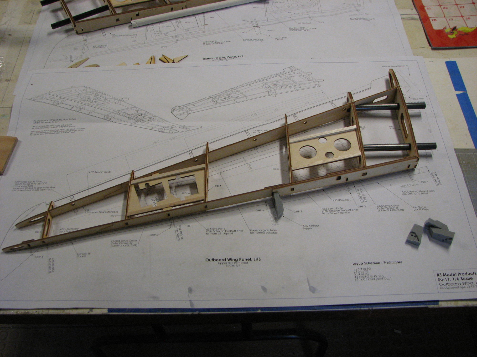
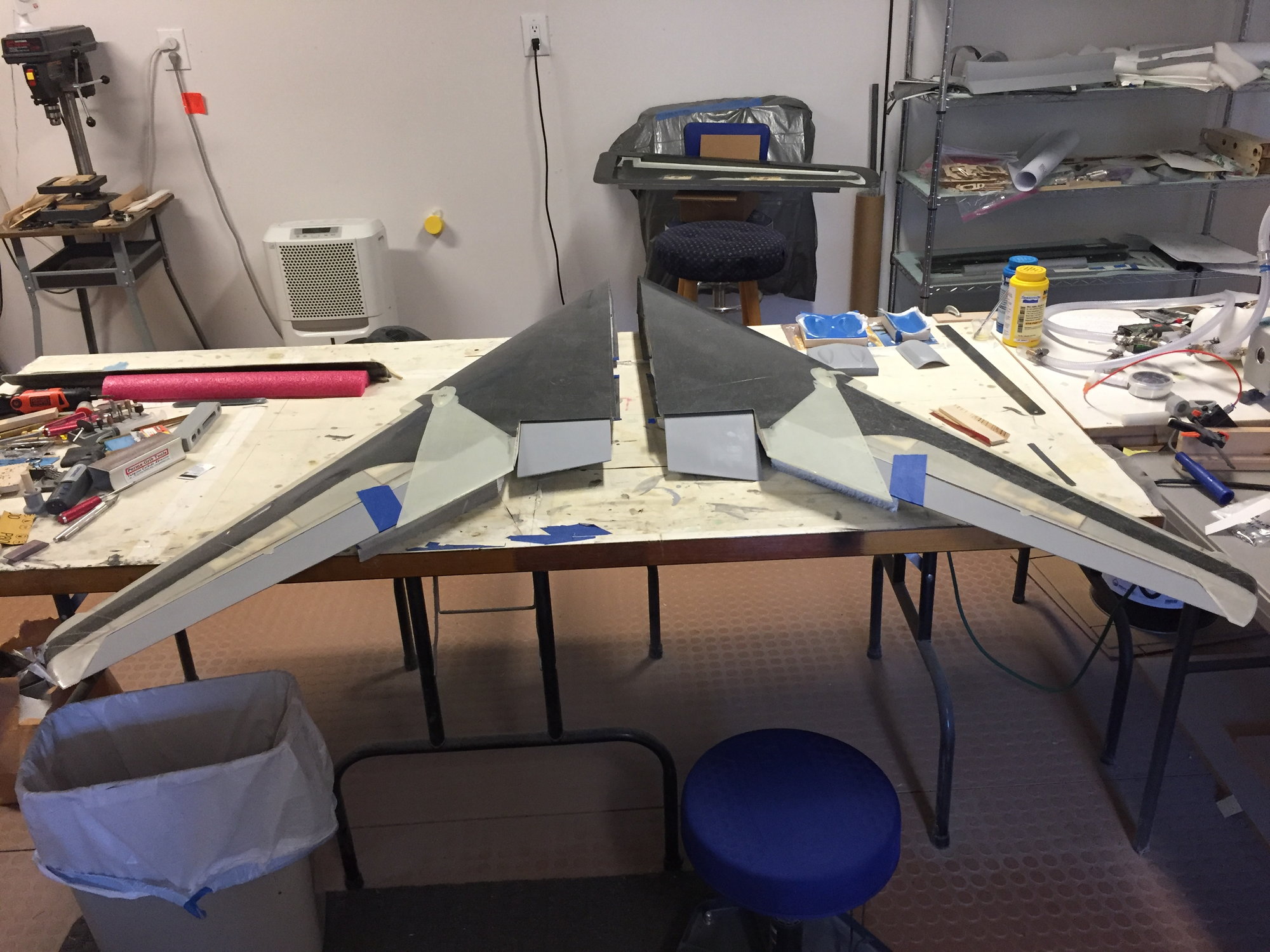
Rigging the Outboard wing structure together, Jan 2020.
Early rigging of some of the parts. I may have been waiting for the carbon plates or the pivot arms, so they are not shown. Also wanted to check to see if the Outboard TE Flap will not collide with the Inboard TE Flap area...
Time to bag the Outboard wing skins, May 2020.
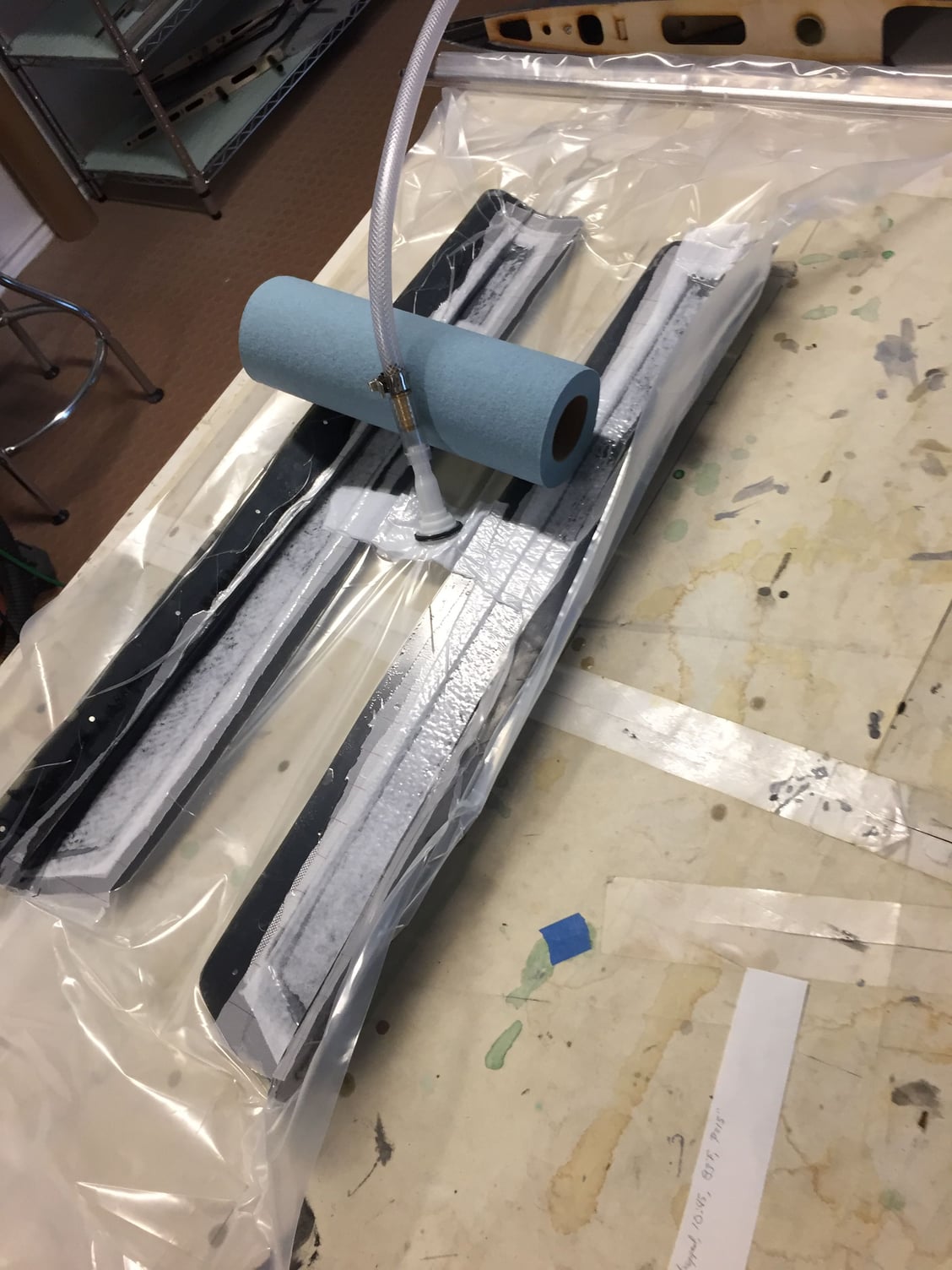
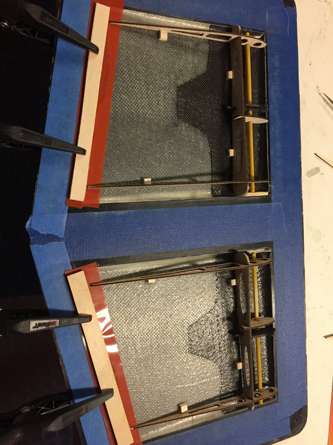
Bagging the LE Slat skins.
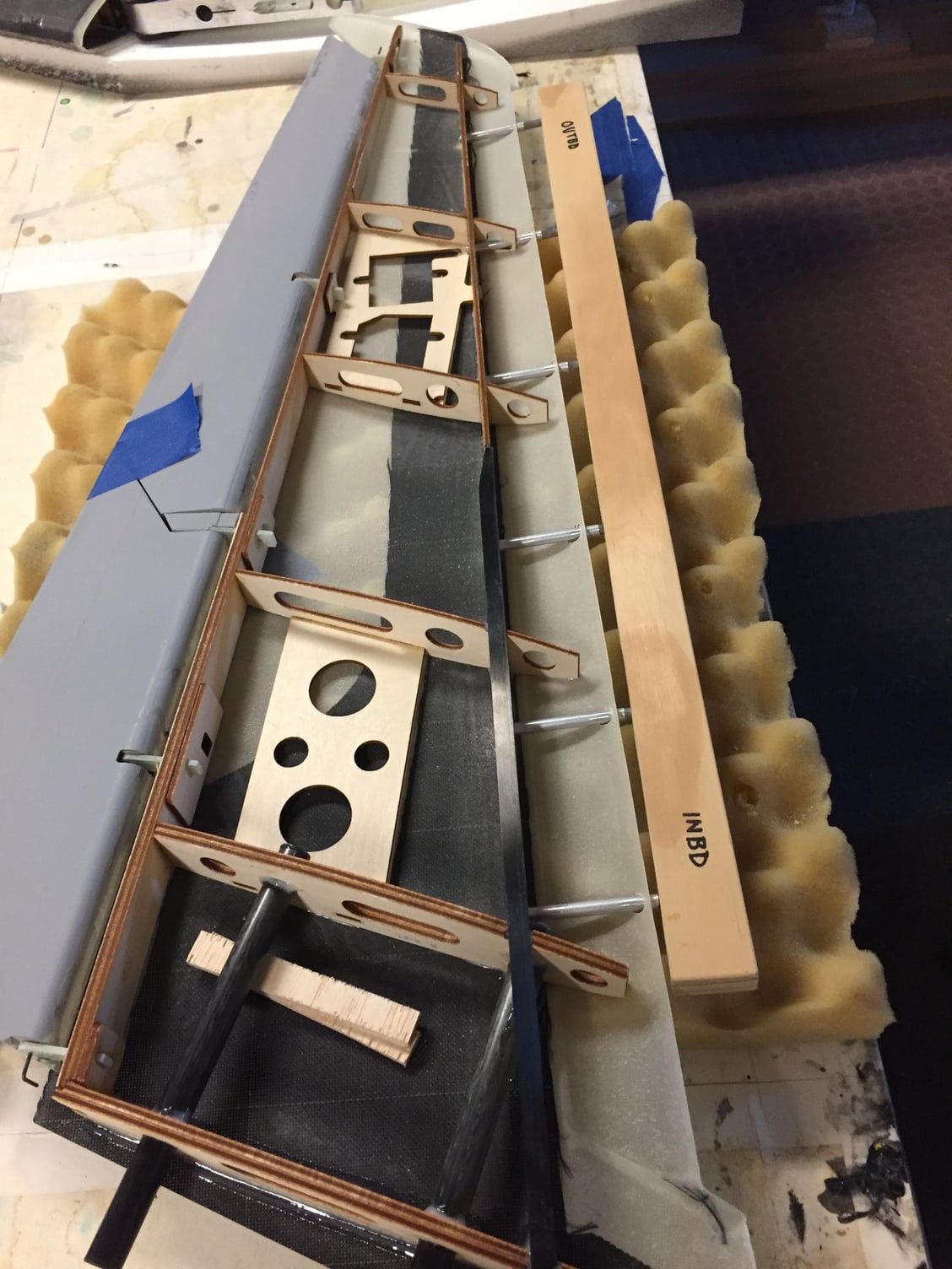
RH panel, lower side - structure has been bonded to the upper skin. I'm using the wood bar with 6 steel rods in it (the Slat Comb) to align the aluminum tubes, which will create the Slat tracks.
LH Outboard wing, closed up, with the back side of the LE Slat - not installed.
Time to throw primer on all of it. :-)
I've made and shown pics of the Ailerons and TE Flaps in work earlier. Rigging the Outboard wing structure together, Jan 2020.
Early rigging of some of the parts. I may have been waiting for the carbon plates or the pivot arms, so they are not shown. Also wanted to check to see if the Outboard TE Flap will not collide with the Inboard TE Flap area...
Time to bag the Outboard wing skins, May 2020.
Bagging the LE Slat skins.
RH panel, lower side - structure has been bonded to the upper skin. I'm using the wood bar with 6 steel rods in it (the Slat Comb) to align the aluminum tubes, which will create the Slat tracks.
LH Outboard wing, closed up, with the back side of the LE Slat - not installed.
Time to throw primer on all of it. :-)
06-18-2021, 03:10 PM
#40
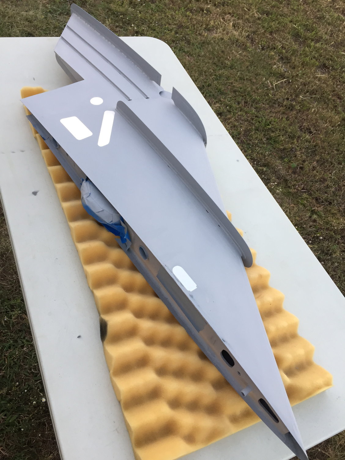
And a bit later, I added some Flite Metal to the inboard parts that are to be unpainted as per the full scale aircraft. I did this a bit more down the road... One can get bored working on a model that is all in nothing but primer... 
Flite metal time.
Flite metal time.
Last edited by Ron S; 06-18-2021 at 03:36 PM. Reason: added a word
06-18-2021, 03:30 PM
#41
After the wing parts had been closed up to the structure, it was a constant process to test fit the Outboard wings to the Inboard wings. I was looking at making sure proper gaps were maintained, and wing incidence was maintained as the wing swept. I was paranoid and just wanted to make sure that I didn't introduce any twists in the wing. Due to the high sweep of the Inboard wing, I had to get one of those Robart 3 foot extensions for my incidence meter. I also found that reading the bubble gage thingie accurately on the incidence meter would bounce around a bit more than I liked, so I eventually bought an electronic angle gage with a little LCD display, and made a mount to use on my Robart incidence meter rail assembly. I also made half a dozen parts to help align the outboard to the inboard wing, and used lots of shims...
I will post more tomorrow.
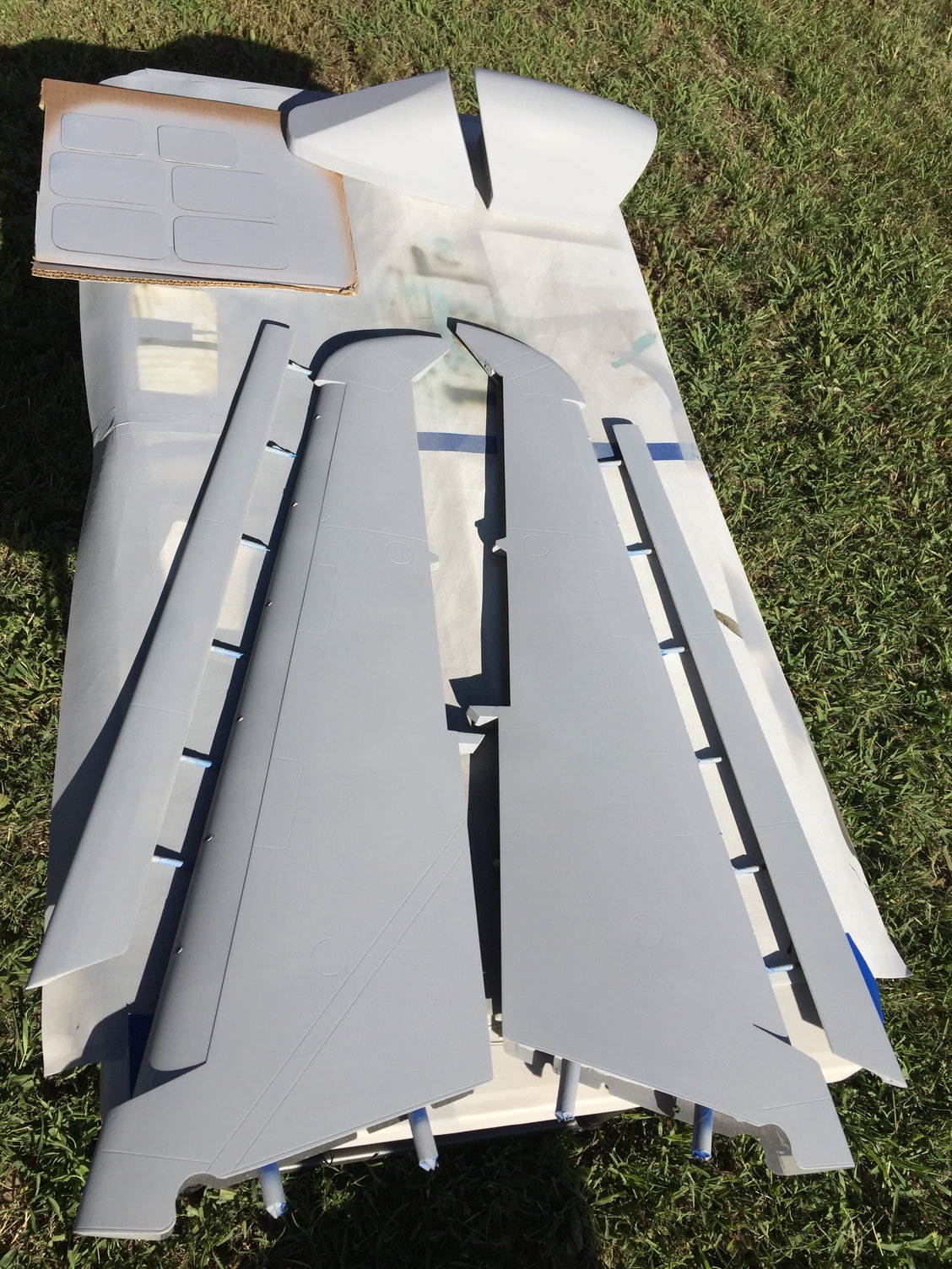
Test fitting wing parts before primer.
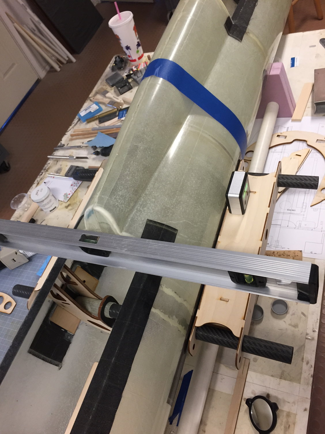
I made 2 laser cut boxes to simulate the inboard wing, and used this to help rig the carbon wingspar tubes / sockets to the fuselage, then rig to get the proper anhedral and incidence. Little silver digital angle meter seen to the right, sitting on one of the wood boxes... I also used this, mounted on my Robart incidence meter.
A pic waay before the wing skins were bonded in place, of the Inboard wing structure, temporarily fitted to the fuselage. The fuselage wingspar sockets and corresponding bulkheads were loose at this time. Also attempting to get some motivation before wing skin attach...
I will post more tomorrow.
Test fitting wing parts before primer.
I made 2 laser cut boxes to simulate the inboard wing, and used this to help rig the carbon wingspar tubes / sockets to the fuselage, then rig to get the proper anhedral and incidence. Little silver digital angle meter seen to the right, sitting on one of the wood boxes... I also used this, mounted on my Robart incidence meter.
A pic waay before the wing skins were bonded in place, of the Inboard wing structure, temporarily fitted to the fuselage. The fuselage wingspar sockets and corresponding bulkheads were loose at this time. Also attempting to get some motivation before wing skin attach...
06-19-2021, 01:33 PM
#42
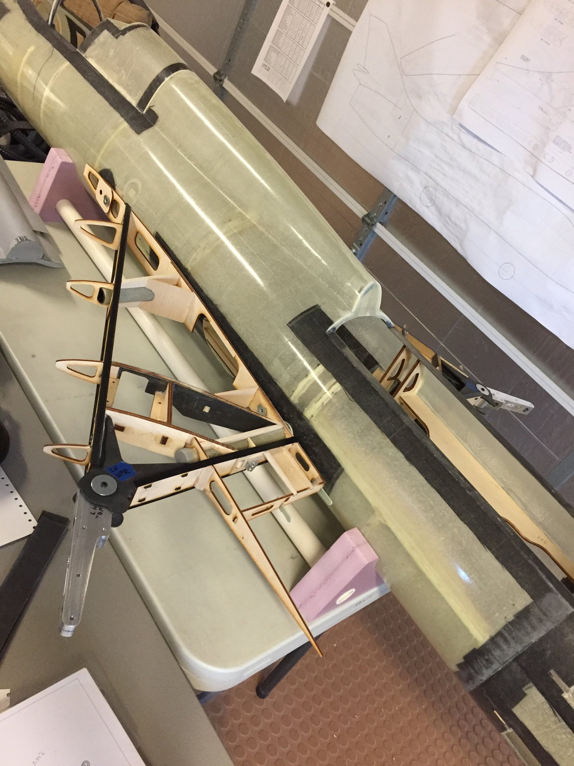
Actually those last two pics looks like the wing carrythru structure WAS already bonded in place. Below is a pic of that same structure outside of the model. It appears I don't have many pics showing the wing rigging, but the wing incidence meter and the digital angle meter was used a lot.
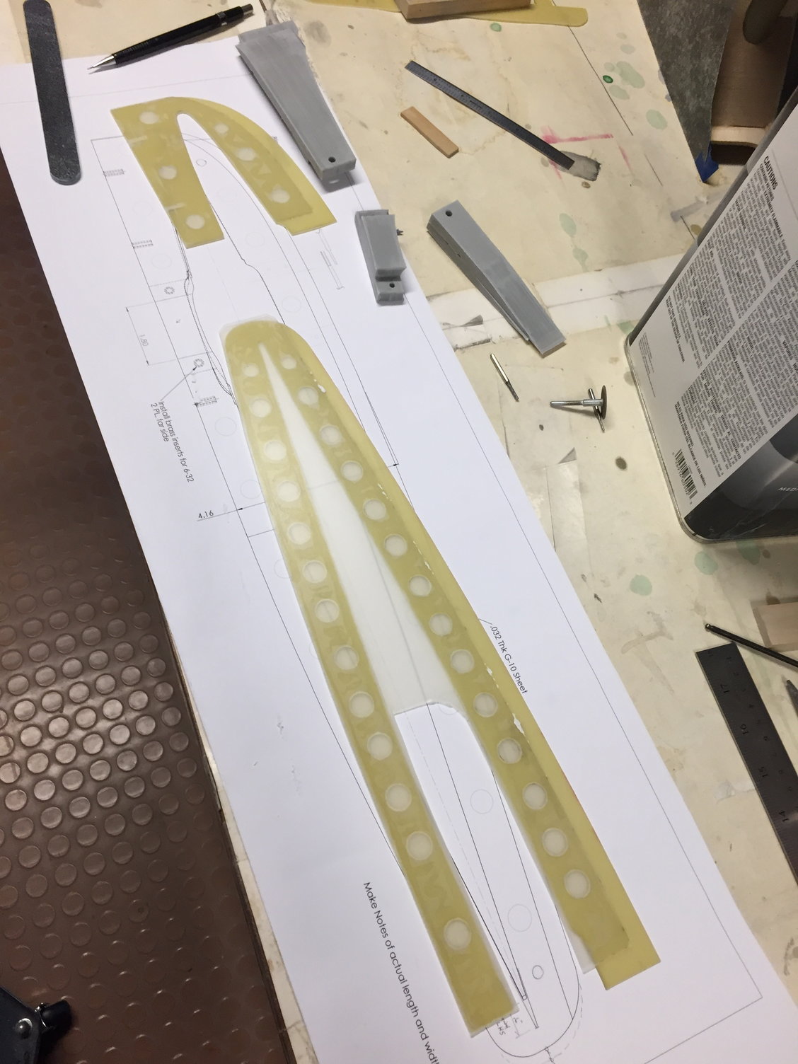
After the wing was rigged to the correct angles, and structure inside the fuselage had been bonded in, it was time to get to work on the inboard wing fences. There is a small wing fence that was made of G-10 or poly-ply, under the wing and just outboard of the inboard TE Flap. After that was installed, I started on the Outboard Fence. This fence wraps all the way around the airfoil, at the wing pivot station, and will need cutouts in the fence on the top and below the wing, to get access to the pivot pin. The lower portion of the fence turns into the outboard pylon, also. and, this fence has varying thicknesses... So I made the fence by stacking G-10 sheets to the needed thickness, Then to create the lower pylon portion of this fence, I added ABS grown pylon halves, to build up to the needed pylon thickness. These were a bunch of work... Plus, since the wing has anhedral, they have to be aligned so that when the model is sitting on the ground, the fences hang straight down, and not normal to the wing plane.
2020 Feb, wing carrythru structure and inbd wing structure.
Some of the parts to build a outboard fence / pylon.
Outboard fence on LH wing. note the cutouts above and below the wing pivot point.
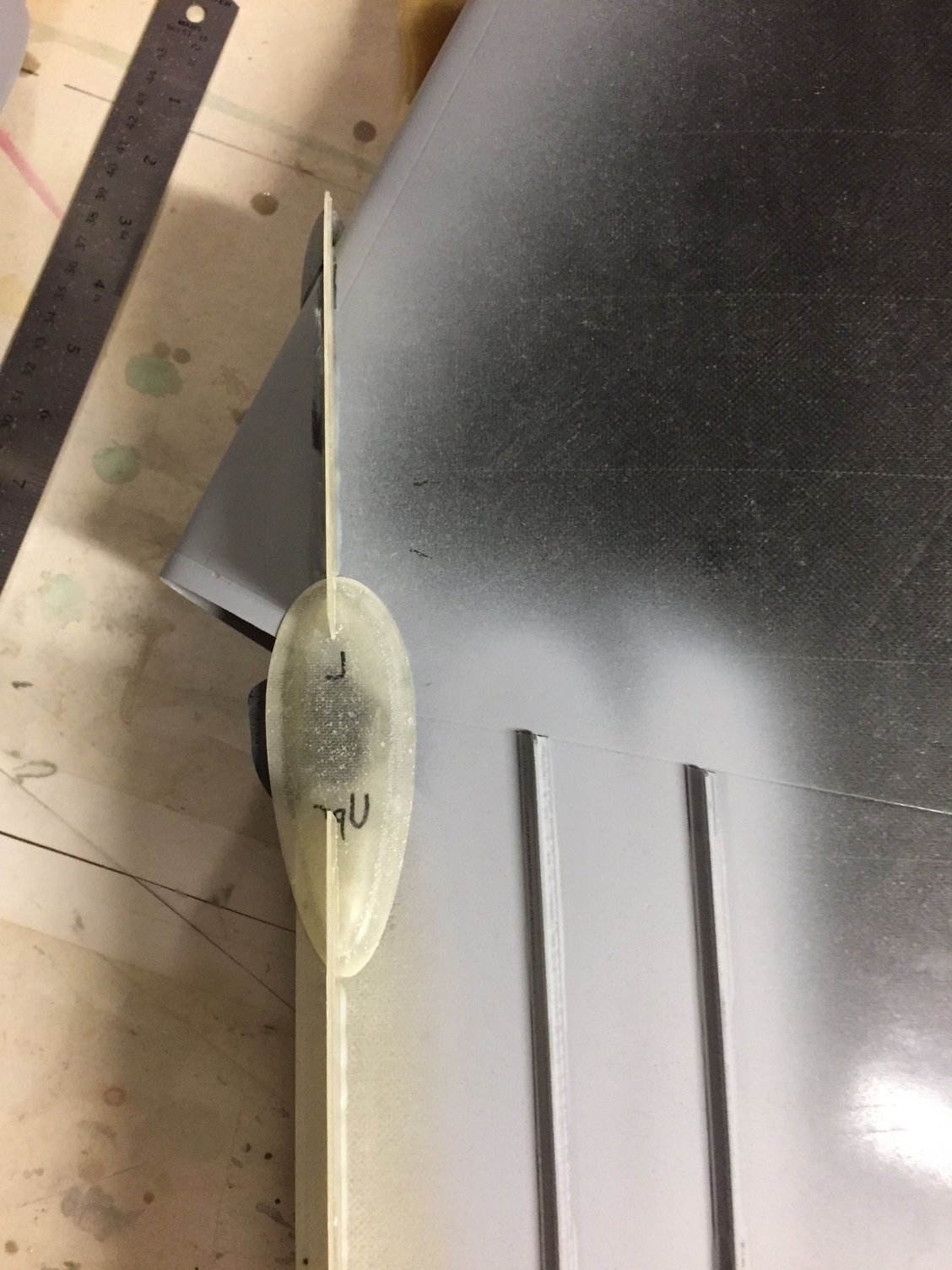
Teardrop shaped pivot covers made and located above and below the wing pivot point. They will later be sliced into sections...
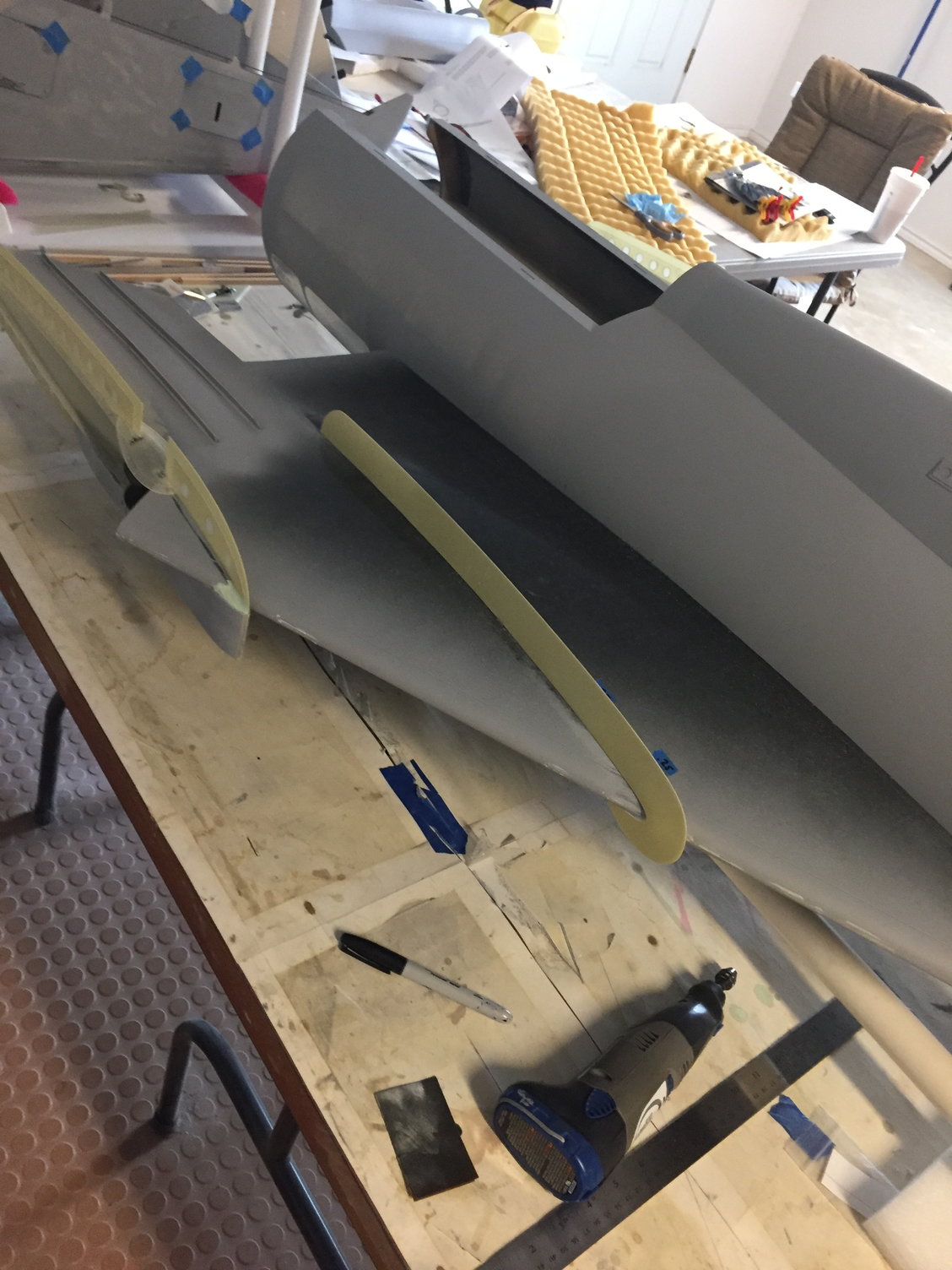
Then, installation of the midboard fence, which is mostly on top of the wing, and slightly wraps around the wing LE.
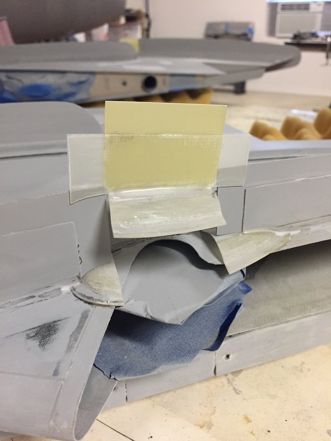
Closeup of the Upper teardrop cover, having been sliced up, with part of the fence attached so it is now removable (slide up and down), but screwed in place for flight.
Pivot cover slid down in place. similar cover made for the lower side, but the lower cover also becomes part of a pylon.
After the wing was rigged to the correct angles, and structure inside the fuselage had been bonded in, it was time to get to work on the inboard wing fences. There is a small wing fence that was made of G-10 or poly-ply, under the wing and just outboard of the inboard TE Flap. After that was installed, I started on the Outboard Fence. This fence wraps all the way around the airfoil, at the wing pivot station, and will need cutouts in the fence on the top and below the wing, to get access to the pivot pin. The lower portion of the fence turns into the outboard pylon, also. and, this fence has varying thicknesses... So I made the fence by stacking G-10 sheets to the needed thickness, Then to create the lower pylon portion of this fence, I added ABS grown pylon halves, to build up to the needed pylon thickness. These were a bunch of work... Plus, since the wing has anhedral, they have to be aligned so that when the model is sitting on the ground, the fences hang straight down, and not normal to the wing plane.
2020 Feb, wing carrythru structure and inbd wing structure.
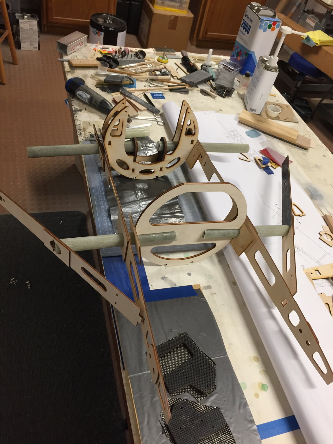
Some of the parts to build a outboard fence / pylon.
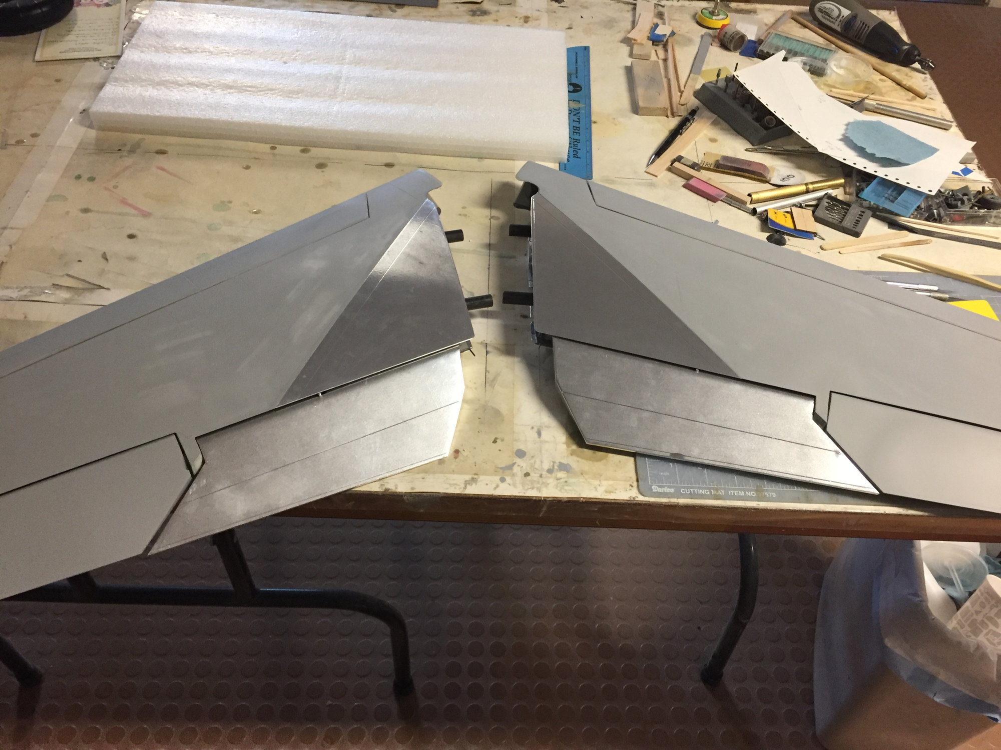
Outboard fence on LH wing. note the cutouts above and below the wing pivot point.
Teardrop shaped pivot covers made and located above and below the wing pivot point. They will later be sliced into sections...
Then, installation of the midboard fence, which is mostly on top of the wing, and slightly wraps around the wing LE.
Closeup of the Upper teardrop cover, having been sliced up, with part of the fence attached so it is now removable (slide up and down), but screwed in place for flight.
Pivot cover slid down in place. similar cover made for the lower side, but the lower cover also becomes part of a pylon.
06-19-2021, 01:48 PM
#43
The inboard wings eventually get T shaped external stiffeners added, to the area near the TE, where there is minimal structure. That is because this area becomes a hollow "glove", where the outboard wing slides into... Also added a few Flite Metal panel shapes for some of the prominent access panels on the wing.
Next, I got back onto the MLG doors. They needed inner liners to stiffen them up, so a mold was made to create those liners. Also, a scalloped part was going to have to be made, as a wheel well, for the portion of the tire that gets hidden inside the fuselage when the gear is up...
Primer time.
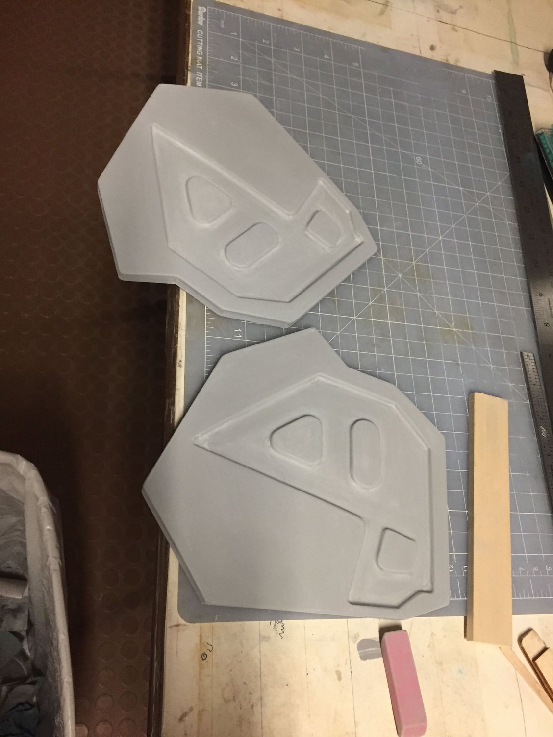
Quick molds made for the MLG inner liners.
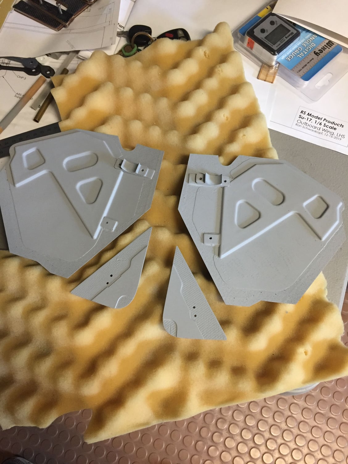
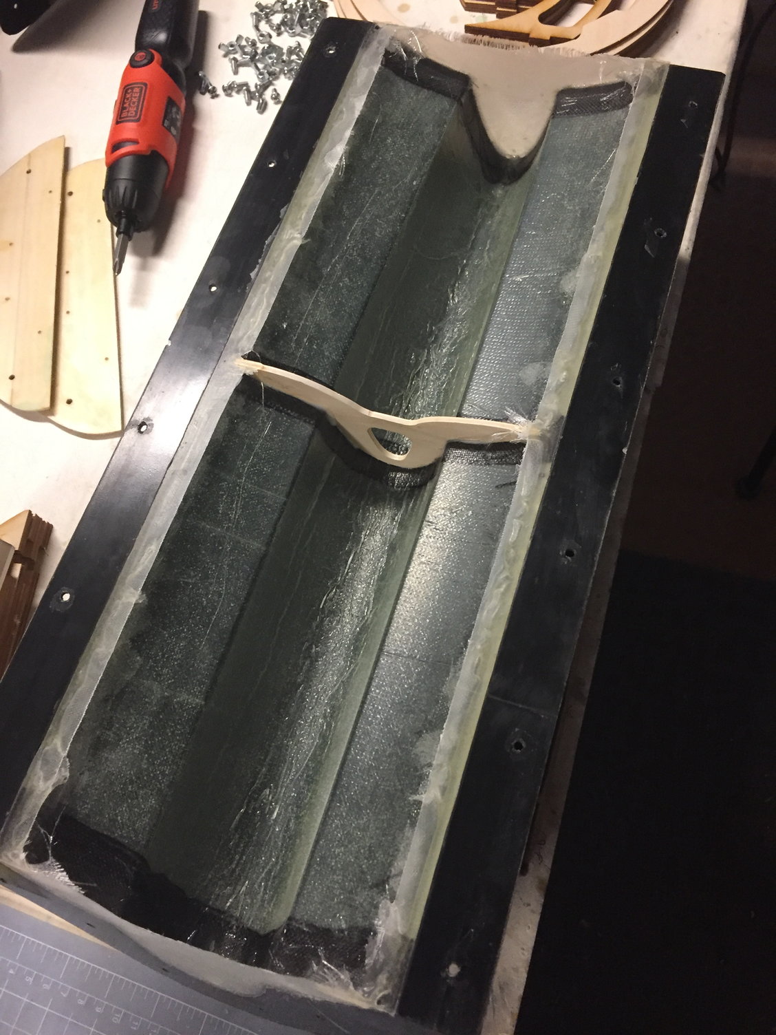
Parts were laid up with the liner molds, then attached to the inside of the MLG doors. the large doors mount directly to the MLG strut, while the smaller triangular door mounts next to the lower "trailing link" portion of the strut. There is one more door that covers right where the main strut pops thru the lower wing - I'm gonna hold off on that door for a while.
Once again, another plug shape was made to create the scalloped cutout in the fuselage, for clearance of the MLG tire when retracted. This was not built into the fuselage plug, because I suspected it was going to involve a lot of fitting, and tolerance buildup. Parts were laid up, then installed and faired in as shown.
Next, I got back onto the MLG doors. They needed inner liners to stiffen them up, so a mold was made to create those liners. Also, a scalloped part was going to have to be made, as a wheel well, for the portion of the tire that gets hidden inside the fuselage when the gear is up...
Primer time.
Quick molds made for the MLG inner liners.
Parts were laid up with the liner molds, then attached to the inside of the MLG doors. the large doors mount directly to the MLG strut, while the smaller triangular door mounts next to the lower "trailing link" portion of the strut. There is one more door that covers right where the main strut pops thru the lower wing - I'm gonna hold off on that door for a while.
Once again, another plug shape was made to create the scalloped cutout in the fuselage, for clearance of the MLG tire when retracted. This was not built into the fuselage plug, because I suspected it was going to involve a lot of fitting, and tolerance buildup. Parts were laid up, then installed and faired in as shown.
06-19-2021, 02:03 PM
#44
I never located any tires for the main landing gear. So, as expected, I was going to have to cast some. Which is okay, because I've always wanted to try this. Shortly before I had cast mine, Mugu had his long MiG-21 thread, where he did just the same, so it gave me some confidence I could atleast get close. Also, long ago, Kevin W had posted how he cast tires for his Me-262.
I had already been casting some parts using Smooth-on mold material, and there is a distributor locally. (Well, 50 mile drive locally...) I had previously made a tire shape already (had a pic of it when I described the MLG), so I headed off to the casting place to see if they had any suggestions - I brought some pics of how I thought I could do it - lets see what I'll need.
I decided to try making the tire out of 85 Durometer 2-part urethane, with a black dye added to it. from the density, and from Mugu's attempts, I suspected I'd end up with a heavy tire. So I wanted to try to install a low density core (like a smaller donut) inside my mold, then do the pour around the core. For the mold, I wanted to try to stick with material I had some experience with, which was a 35-45 Durometer material, if I remember correctly. It is the bright blue stuff in the pics.
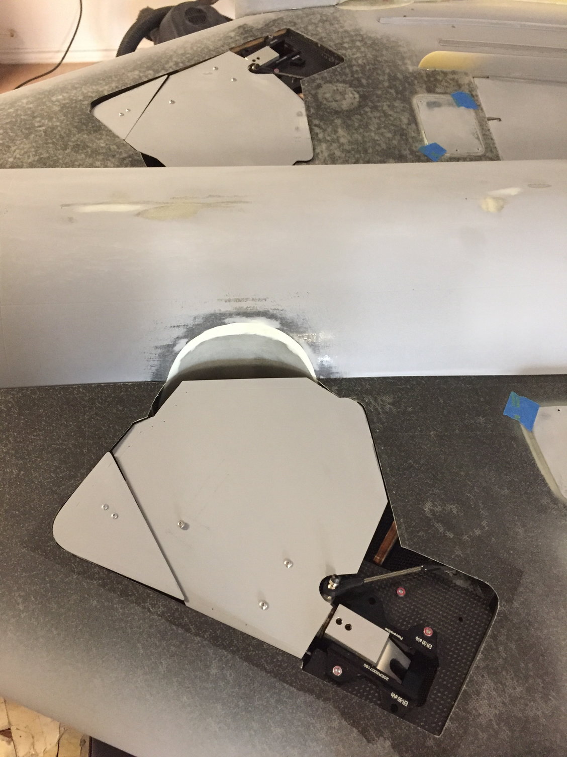
After making a little box, and making parting planes to pour the mold, I started pouring the mold material around the tire plug.
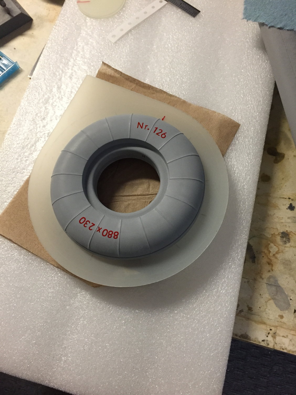
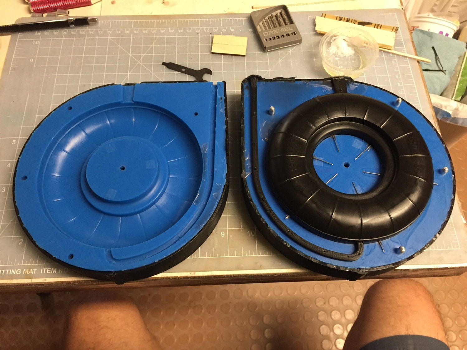
Plug with parting plane. Need to add sides to make a "pool"...
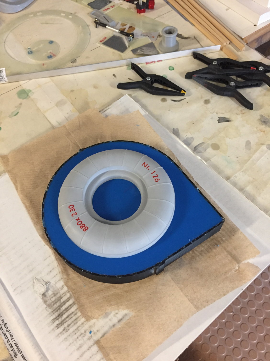
First half has been poured, and parting plane removed. Need to spray mold release, then pour this last side...
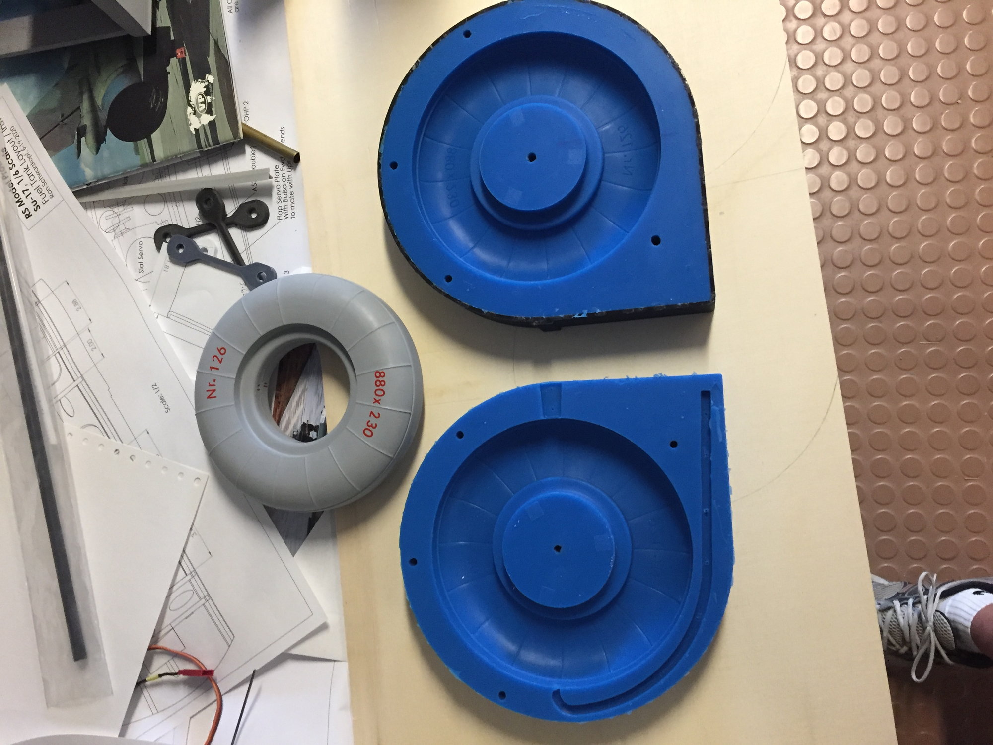
Molds are done, and nothing stuck together! So far, so good.
So, as expected, I was going to have to cast some. Which is okay, because I've always wanted to try this. Shortly before I had cast mine, Mugu had his long MiG-21 thread, where he did just the same, so it gave me some confidence I could atleast get close. Also, long ago, Kevin W had posted how he cast tires for his Me-262.I had already been casting some parts using Smooth-on mold material, and there is a distributor locally. (Well, 50 mile drive locally...) I had previously made a tire shape already (had a pic of it when I described the MLG), so I headed off to the casting place to see if they had any suggestions - I brought some pics of how I thought I could do it - lets see what I'll need.
I decided to try making the tire out of 85 Durometer 2-part urethane, with a black dye added to it. from the density, and from Mugu's attempts, I suspected I'd end up with a heavy tire. So I wanted to try to install a low density core (like a smaller donut) inside my mold, then do the pour around the core. For the mold, I wanted to try to stick with material I had some experience with, which was a 35-45 Durometer material, if I remember correctly. It is the bright blue stuff in the pics.
After making a little box, and making parting planes to pour the mold, I started pouring the mold material around the tire plug.
Plug with parting plane. Need to add sides to make a "pool"...
First half has been poured, and parting plane removed. Need to spray mold release, then pour this last side...
Molds are done, and nothing stuck together! So far, so good.
Last edited by Ron S; 06-19-2021 at 02:09 PM. Reason: forgot to add the pics.
06-19-2021, 02:25 PM
#45
It had been suggested I might want to add a flow path, so when the tire material is being injected, it fills from the bottom. So I created the J shaped path in the mold. I'm not saying this is the best way to do this - I'd like to spend some time seeing if I can improve on this whole process, but if I can get 2 usable tires, I'm gonna run with them.
It looked like I was gonna need some big syringes (Amazon), and when the tire material is mixed and in the syringes, I was going to have to work very fast. I forget what the working time with the material was, but I wish it was double...
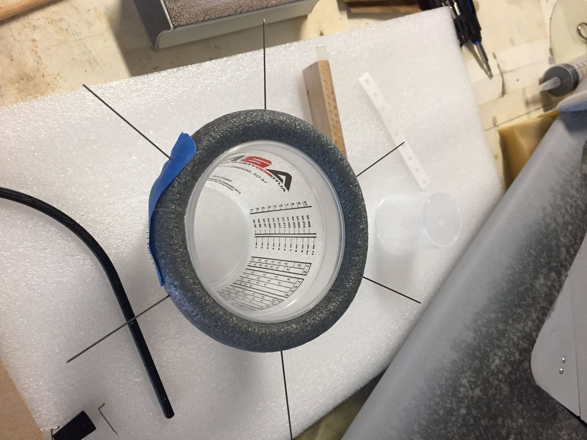
Pic of the foam core, I think 5/8" diameter, sitting on top of a plastic cup to keep it round. I've stuck it with .032 wires, which will suspend the core in the mold. (In theory!)
Molds, with locating pins added. you can probably guess the core assembly will get clamped in place when the molds are clamped together, suspending the core. That's the plan, anyway! What could go wrong?
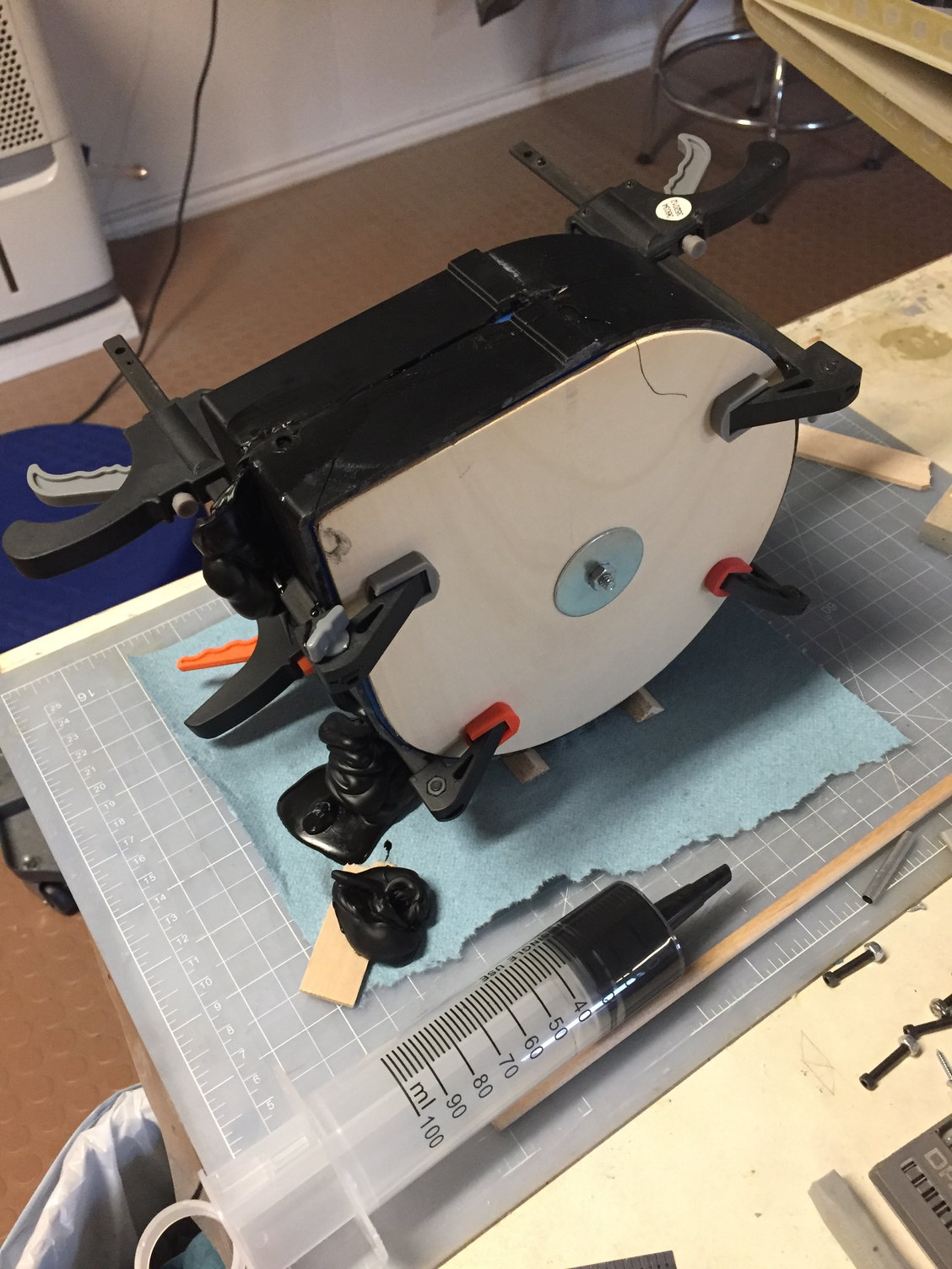
Black tire mixed up, and time to inject like the wind... As the minutes tick by, the stuff gets thicker and thicker. Be prepared to make a mess. We inject thru a little port in the top, and there's a bigger port that will dump access when you've filled it to the top.
Came back the following day, because my shop smelled like holy heck. But I got a usable tire out of it, with some flaws, but they could be addressed. :-) Time to make more until I run out of material because the stuff has a very short shelf life once the containers are opened.
It looked like I was gonna need some big syringes (Amazon), and when the tire material is mixed and in the syringes, I was going to have to work very fast. I forget what the working time with the material was, but I wish it was double...
Pic of the foam core, I think 5/8" diameter, sitting on top of a plastic cup to keep it round. I've stuck it with .032 wires, which will suspend the core in the mold. (In theory!)
Molds, with locating pins added. you can probably guess the core assembly will get clamped in place when the molds are clamped together, suspending the core. That's the plan, anyway! What could go wrong?
Black tire mixed up, and time to inject like the wind... As the minutes tick by, the stuff gets thicker and thicker. Be prepared to make a mess. We inject thru a little port in the top, and there's a bigger port that will dump access when you've filled it to the top.
Came back the following day, because my shop smelled like holy heck. But I got a usable tire out of it, with some flaws, but they could be addressed. :-) Time to make more until I run out of material because the stuff has a very short shelf life once the containers are opened.
Last edited by Ron S; 06-19-2021 at 02:34 PM. Reason: typo
06-19-2021, 02:30 PM
#46
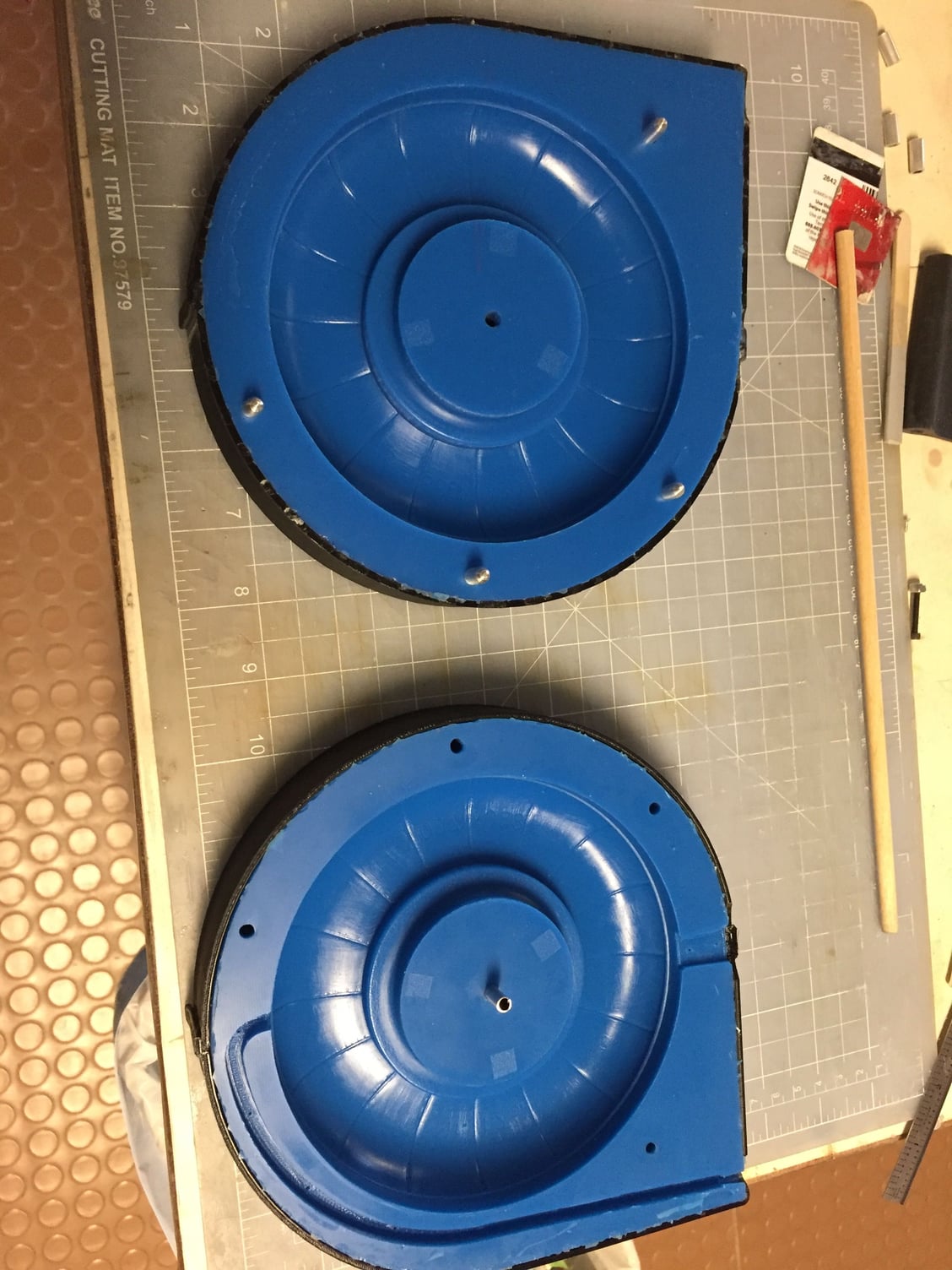
I ended up making 2 full usable tires, and a third which had a bit of a small air cavity. I'm pretty sure this can be filled later. But I put the third tire to the side for now, and played around with sticking pins around the tire to see if I could detect the core... I became confident these would be usable tires, but making a perfect tire was going to take more experimentation. I made a list of things to try next time (to improve on the process), then moved on.
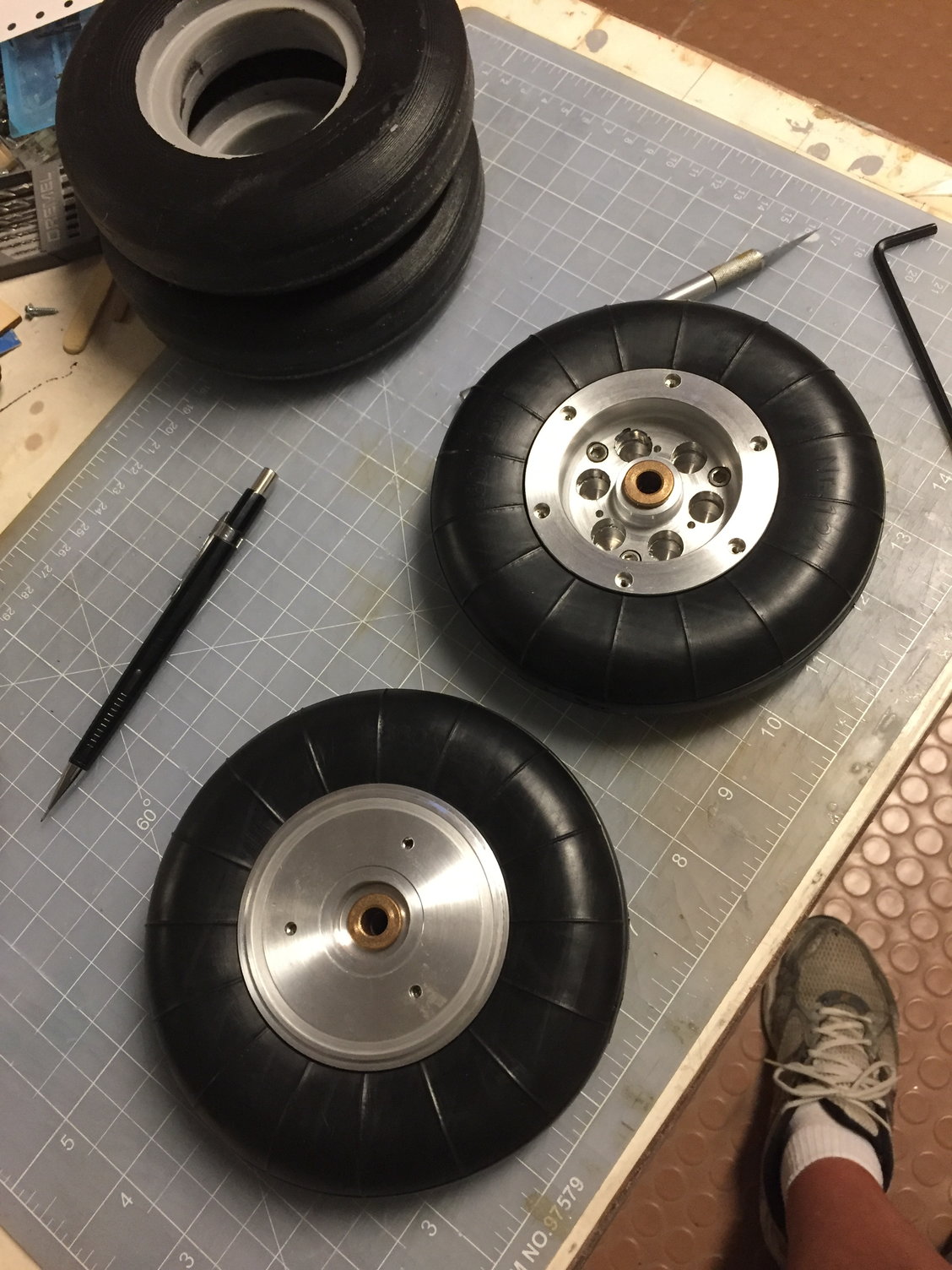
2 usable tires.
2 usable tires.
06-19-2021, 03:10 PM
#47
From when I started this project, I was pretty much assuming I was going to fly the model with my Futaba 18SZ transmitter. I realized I was going to have to do some servo doubling up, with "matchbox" type devices (or Futaba used to have MSA-10s, which would allow you to run up to 4 servos with one channel, etc)... At some point in time I think I saw a thread from Gunrad (? I'll correct that) using a distribution box from AR, for an F-22. Buck Garza ordered one up and started using it on his Skymaster F-4, so eventually I decided to pick one up.
So I was pretty tied up with molds and parts, but I did order one, and eventually I started playing around with it (it sat around for several months), and I think this product made my project do-able.
So this, of course, is the Smoothflite RRS, from Advanced Radio ( Dreamworks had them in stock at the time). Nothing new to some of you... It allows me to run 2 Futaba 7008 receivers (never felt the need to try that before), 2 Rx power inputs, and run the whole thing at 7.4 volts. It still allows for telemetry (which I wanted to do at some point), has built in gyro functions (okay, I admit I've been flying RC for 30+ years, and have 2-3 gyros (in the box still), but have never used gyros in my models ), and allows for up to 26 servo outputs. I was getting close to needing that many channel outputs ( if one counts telemetry).
I didn't want to try another radio mfgr, because I'd want to try the setup on anther airplane first, and didn't want to spend that kind of time away from this project.
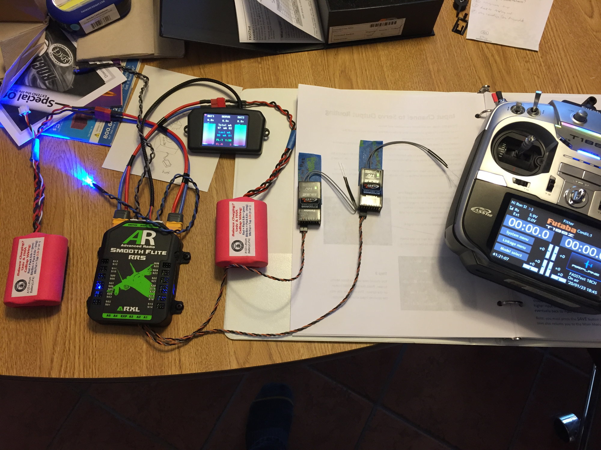
Testing Smoothflite with A123 batteries before switch to 7.4v...
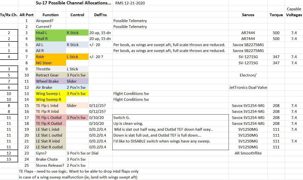
Shows AR Output port usage - either needed, or as future allocation...
So I was pretty tied up with molds and parts, but I did order one, and eventually I started playing around with it (it sat around for several months), and I think this product made my project do-able.
So this, of course, is the Smoothflite RRS, from Advanced Radio ( Dreamworks had them in stock at the time). Nothing new to some of you... It allows me to run 2 Futaba 7008 receivers (never felt the need to try that before), 2 Rx power inputs, and run the whole thing at 7.4 volts. It still allows for telemetry (which I wanted to do at some point), has built in gyro functions (okay, I admit I've been flying RC for 30+ years, and have 2-3 gyros (in the box still), but have never used gyros in my models
), and allows for up to 26 servo outputs. I was getting close to needing that many channel outputs ( if one counts telemetry).I didn't want to try another radio mfgr, because I'd want to try the setup on anther airplane first, and didn't want to spend that kind of time away from this project.
Testing Smoothflite with A123 batteries before switch to 7.4v...
Shows AR Output port usage - either needed, or as future allocation...
Last edited by Ron S; 06-19-2021 at 03:11 PM. Reason: typo
06-19-2021, 03:19 PM
#48

Seriously impressive.
Regards,
Regards,
 06-20-2021, 11:03 AM
#50
Thanks guys
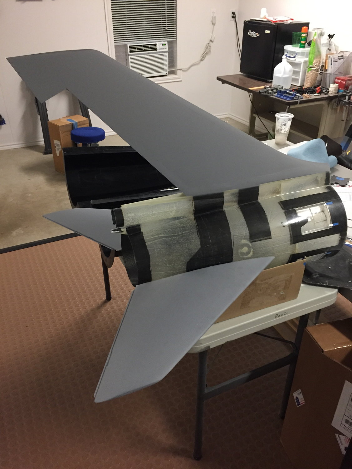
August 2020, we had a local club meeting, and the club was considering having their first jet event, so Paul B and myself thought it might stir up some interest if we were to bring our scratch build projects to a club meeting. One of my favorite pics below, with 2 unfinished projects well underway (Su-17, and Paul's Buccaneer). I like the pic because of where the sun is - I don't know why.
We had several jet events coming up in Sept, Oct, Nov, and with still a lot of mechanical things to do on the Fitter, I was realizing there was little chance of getting a test flight on the Fitter by end of year. I wanted to get atleast some of the paint on the model, but I still had to finalize the pivot hardware, work up CG location, canopy, all of the control surface programming, get the cockpit in work, and another round of working on the landing gear (final pins, springs, etc.) So I decided to move ahead with these things, along with paint since we had some nice weather for October thru December.
Also, had to finalize color schemes. I had been collecting pics for years online, but I think to do the job right, I really wanted first hand pics, and that wasn't go to happen for 2020... Too difficult to communicate to other groups in Europe to get pics - I was having no success with the avenues I took. Part of the problem is I think I'd need to work this a bit harder, but I didn't want to slow down the model building.
In the end I decided if I wasn't gonna be able to get really good color, (and markings, fastener location, stencil ) documentation, I would go with atleast an interesting color scheme that I had found some history on, and it's a Soviet airplane so that should be the insignia on the model. This aircraft operated at an Soviet run airfield (Gross-Dolln airfield) in East Germany until 1994, until the entire "20th Guards" unit pulled out of Templin. They operated some 40 or so Su-17s there.
From what I can find, it seems when the entire unit pulled out, Yellow 27 and others made their way to Chebinki Air Field in Russia, for storage. There, the aircraft sadly was left to deteriorate, and probably got cannibalized as needed. The last pic in this post was from about 2008 at Chebinki.
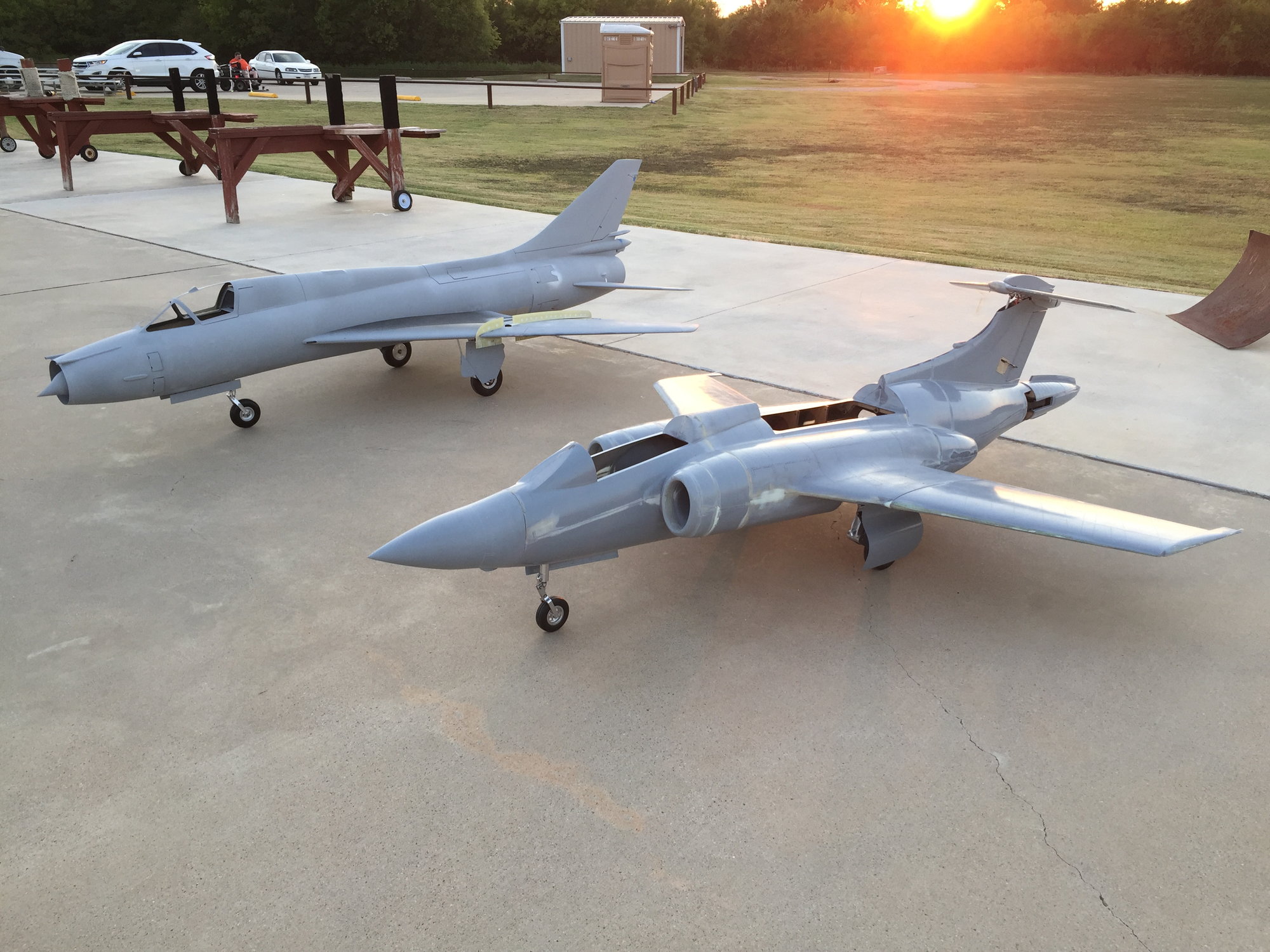
Fitter and Buccaneer (in work) at T-bird Field.
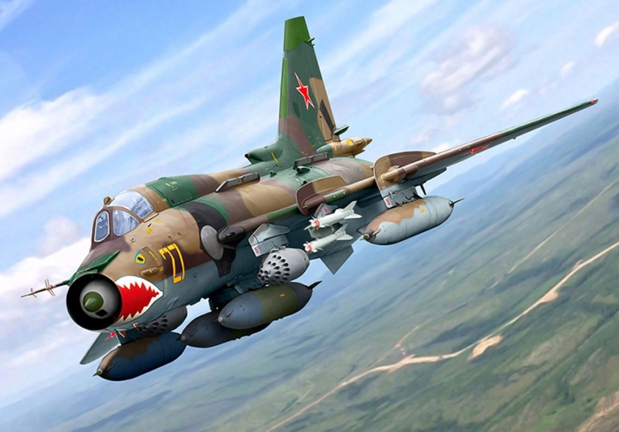
Yellow 27 su-17M4 color scheme with a shark mouth. :-)
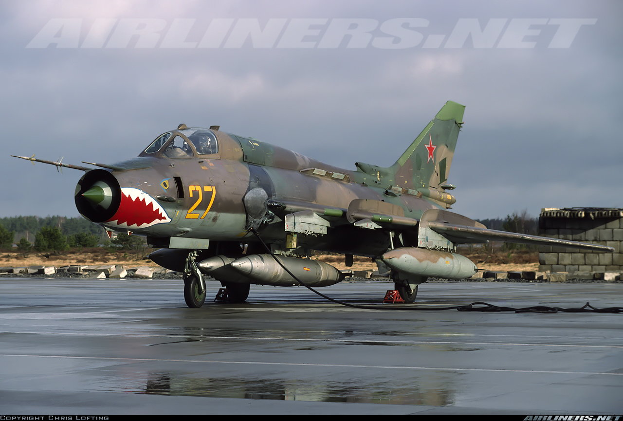
Yellow 27 readying for a flight - probably heading back to Soviet Union.
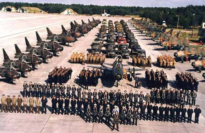
20th GvAPIB operating at Gross Dolln Air Base, until April 1994.
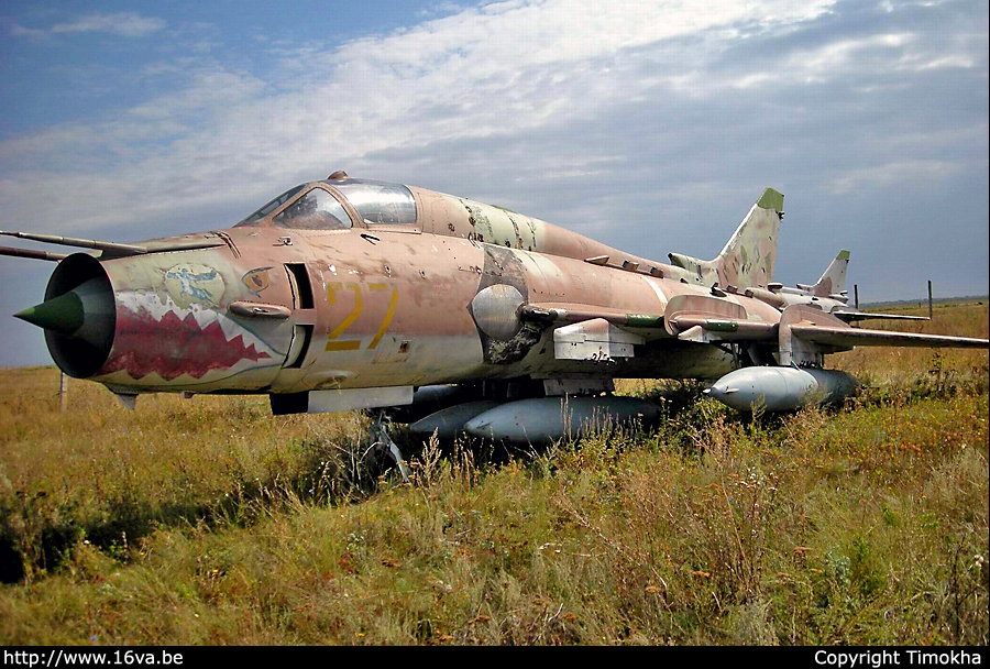
In storage with its other buddies... :-(
August 2020, we had a local club meeting, and the club was considering having their first jet event, so Paul B and myself thought it might stir up some interest if we were to bring our scratch build projects to a club meeting. One of my favorite pics below, with 2 unfinished projects well underway (Su-17, and Paul's Buccaneer). I like the pic because of where the sun is - I don't know why.
We had several jet events coming up in Sept, Oct, Nov, and with still a lot of mechanical things to do on the Fitter, I was realizing there was little chance of getting a test flight on the Fitter by end of year. I wanted to get atleast some of the paint on the model, but I still had to finalize the pivot hardware, work up CG location, canopy, all of the control surface programming, get the cockpit in work, and another round of working on the landing gear (final pins, springs, etc.) So I decided to move ahead with these things, along with paint since we had some nice weather for October thru December.
Also, had to finalize color schemes. I had been collecting pics for years online, but I think to do the job right, I really wanted first hand pics, and that wasn't go to happen for 2020... Too difficult to communicate to other groups in Europe to get pics - I was having no success with the avenues I took. Part of the problem is I think I'd need to work this a bit harder, but I didn't want to slow down the model building.
In the end I decided if I wasn't gonna be able to get really good color, (and markings, fastener location, stencil ) documentation, I would go with atleast an interesting color scheme that I had found some history on, and it's a Soviet airplane so that should be the insignia on the model.
This aircraft operated at an Soviet run airfield (Gross-Dolln airfield) in East Germany until 1994, until the entire "20th Guards" unit pulled out of Templin. They operated some 40 or so Su-17s there.From what I can find, it seems when the entire unit pulled out, Yellow 27 and others made their way to Chebinki Air Field in Russia, for storage. There, the aircraft sadly was left to deteriorate, and probably got cannibalized as needed. The last pic in this post was from about 2008 at Chebinki.
Fitter and Buccaneer (in work) at T-bird Field.
Yellow 27 su-17M4 color scheme with a shark mouth. :-)
Yellow 27 readying for a flight - probably heading back to Soviet Union.
20th GvAPIB operating at Gross Dolln Air Base, until April 1994.
In storage with its other buddies... :-(
Last edited by Ron S; 06-20-2021 at 11:04 AM. Reason: more work
The following users liked this post:
grbaker (06-20-2021)