


Sukhoi Su-17 M4 "Fitter", 1/6 Scale Project
 06-14-2021, 01:11 PM
#1

Howdy,
I have held off on doing this because I didn't really want to do a full build thread as several others have done (and have done VERY well). I suspected it would get too time consuming. So I will do what might be a very time compressed build thread.
A few years back (2017) I was looking to do a scratch build project - and perhaps make a few builder kits if the project was going in the right direction. I was going in a couple different aircraft directions, but in the end, I decided to start to amass information / documentation on the Su-17 Fitter, because:
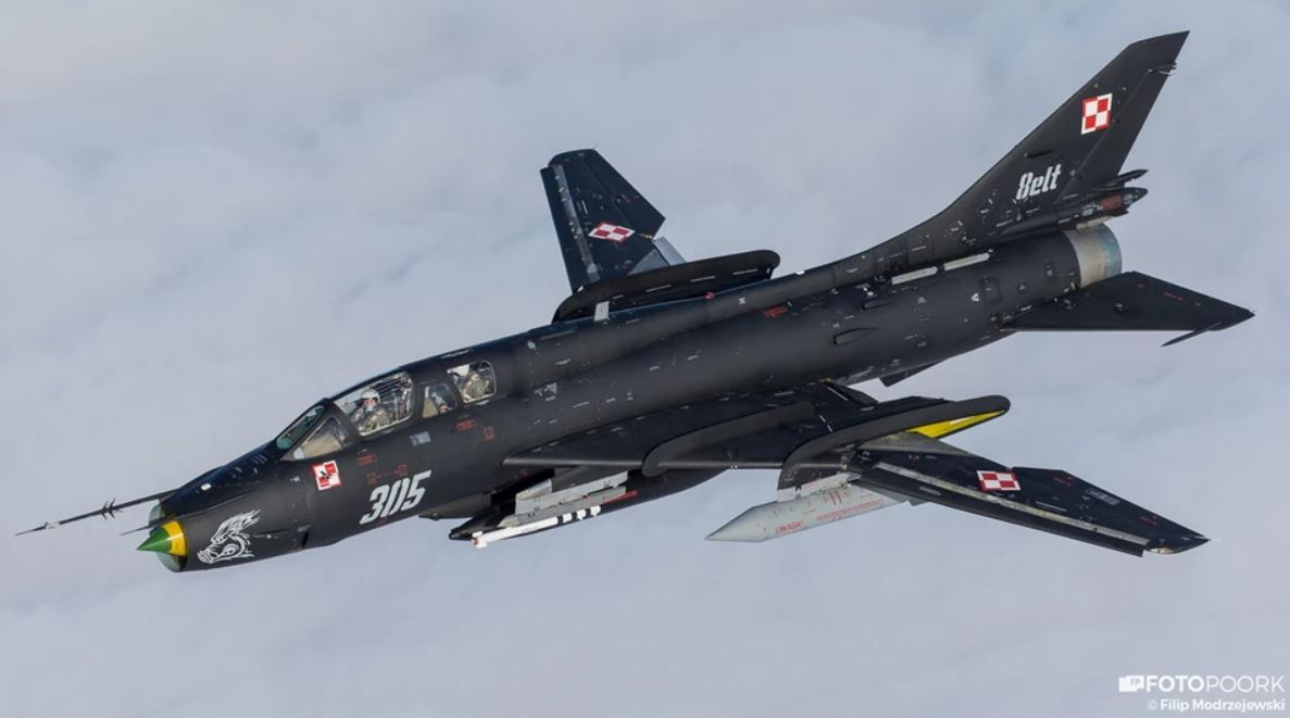
1.) The Polish Air Force still flies them and had just recently updated their aircraft with new color schemes, so recent photographs online were available,
2.) For modelers in the US, it is a relatively obscure aircraft (even though several countries had flown them), so I would not likely run into someone else building one (?? ??),
??),
3.) It is a somewhat complex aircraft, with lots of functions a modeler could add (inbd and outbd flaps, slats, swing wing, drag chute, involved main landing gear, etc),
4.) There are several viewable at museums (although unfortunately, not here in the US),
5.) Lots of color schemes available, if you can find the documentation (from bare metal finish, to various shades of Camo, and a few specially colored in almost sport-type schemes).
6.) It's mostly an attack aircraft, so one could add tons of different types of stores.
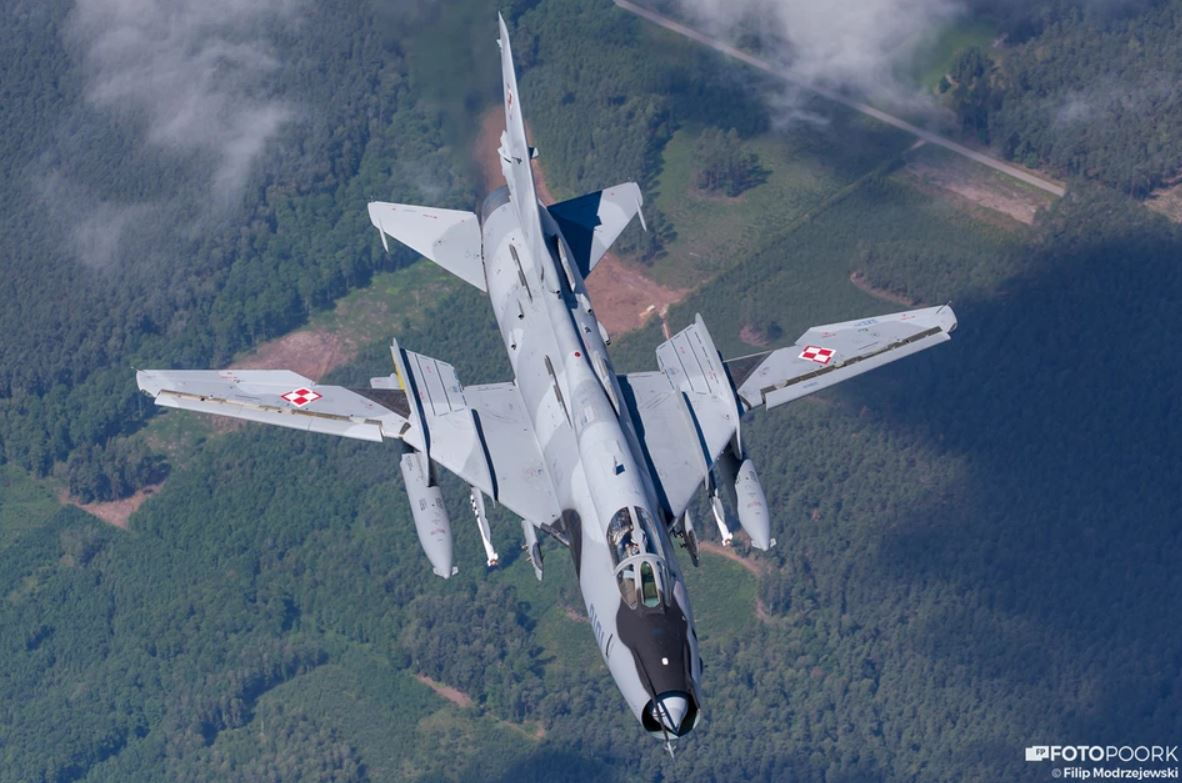
Polish Su-22M4 with updated colors, and wings full forward.
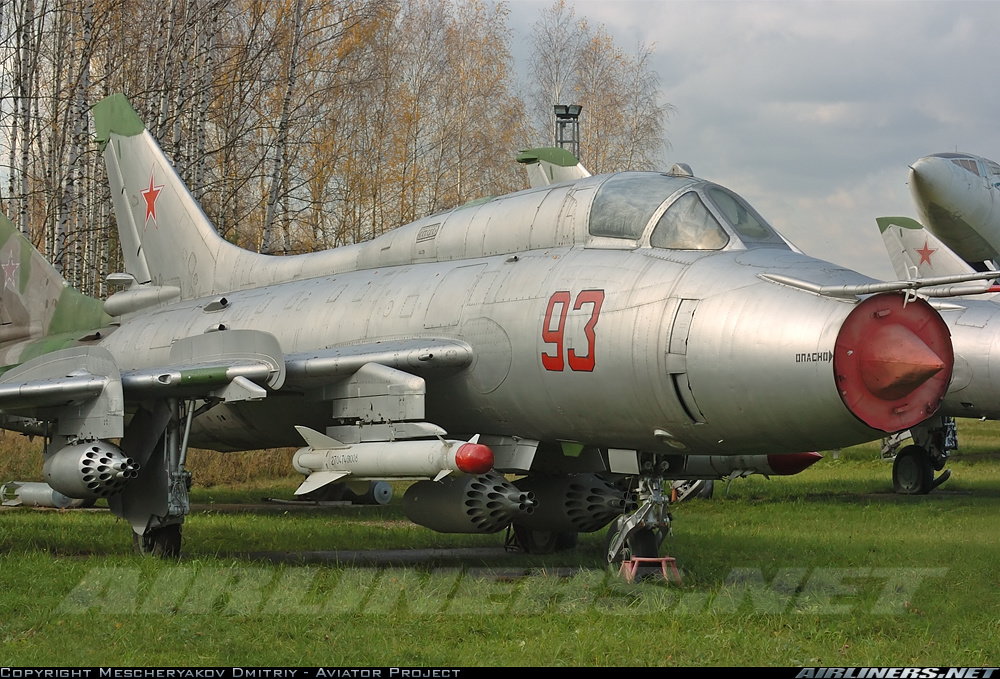
Su-17M3 with wings full aft, bare metal, at Monino Air Museum.
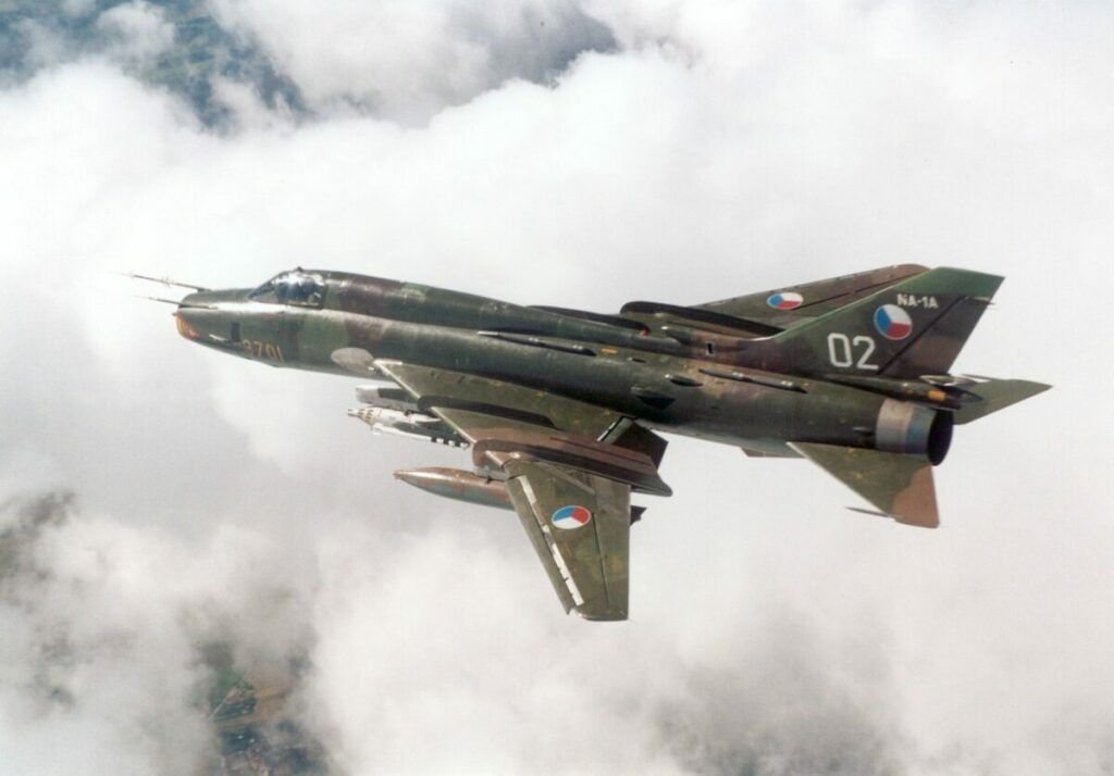
Czech Su-22M4 with wings mid-sweep.
I have held off on doing this because I didn't really want to do a full build thread as several others have done (and have done VERY well). I suspected it would get too time consuming. So I will do what might be a very time compressed build thread.
A few years back (2017) I was looking to do a scratch build project - and perhaps make a few builder kits if the project was going in the right direction. I was going in a couple different aircraft directions, but in the end, I decided to start to amass information / documentation on the Su-17 Fitter, because:
1.) The Polish Air Force still flies them and had just recently updated their aircraft with new color schemes, so recent photographs online were available,
2.) For modelers in the US, it is a relatively obscure aircraft (even though several countries had flown them), so I would not likely run into someone else building one (??
??),3.) It is a somewhat complex aircraft, with lots of functions a modeler could add (inbd and outbd flaps, slats, swing wing, drag chute, involved main landing gear, etc),
4.) There are several viewable at museums (although unfortunately, not here in the US),
5.) Lots of color schemes available, if you can find the documentation (from bare metal finish, to various shades of Camo, and a few specially colored in almost sport-type schemes).
6.) It's mostly an attack aircraft, so one could add tons of different types of stores.
Polish Su-22M4 with updated colors, and wings full forward.
Su-17M3 with wings full aft, bare metal, at Monino Air Museum.
Czech Su-22M4 with wings mid-sweep.
 06-14-2021, 01:43 PM
#2
A bit about the actual aircraft. This aircraft was a further development of the Su-7, which was flying around the 1950-70s. The Su-7 had high takeoff and landing speeds, and the manufacturer was looking to improve on these characteristics, from going to a delta wing planform, to trying out a variable sweep wing. The extreme leading edge sweep (around 62 degrees sweepback) of the wing is beneficial for high mach number flight, but is a detriment to low speed flight. Variable sweep became "a thing" back in the 60s, with the F-111 in the US, along with a few predecessor test aircraft (Bell X-5).
After several variants, the swing wing version of the Su-7 turned into the Su-17. Different external shapings of the aircraft caused it to eventually develop a larger dorsal spine that would extend to the vertical fin. The Su-17M3 has a dorsal spine that blends with a nice curve into the vertical fin leading edge. On the M4 variant, that curve is replaced by an additional air inlet and exhaust, which I suspect is used for avionics cooling. There is also a UM3 variant, which removes a wing root gun, and becomes a 2 place aircraft, for pilot instruction.
The notation of Su-17 is used to designate the Russian aircraft ( or Soviet aircraft). This aircraft was exported to several countries (Poland, Hungary, East Germany, Czechoslovakia) - the export aircraft were designated as Su-22. So there are also Su-22M4, UM3, M4 variants. In a few cases the export aircraft had larger diameter engines. I'd suspect the avionics would also vary depending on the receiving nation.
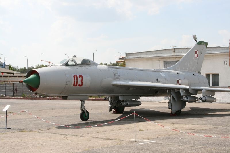
Polish Su-7 (fixed wing)
polish Su-22 UM3 in special color scheme
This aircraft was a further development of the Su-7, which was flying around the 1950-70s. The Su-7 had high takeoff and landing speeds, and the manufacturer was looking to improve on these characteristics, from going to a delta wing planform, to trying out a variable sweep wing. The extreme leading edge sweep (around 62 degrees sweepback) of the wing is beneficial for high mach number flight, but is a detriment to low speed flight. Variable sweep became "a thing" back in the 60s, with the F-111 in the US, along with a few predecessor test aircraft (Bell X-5).After several variants, the swing wing version of the Su-7 turned into the Su-17. Different external shapings of the aircraft caused it to eventually develop a larger dorsal spine that would extend to the vertical fin. The Su-17M3 has a dorsal spine that blends with a nice curve into the vertical fin leading edge. On the M4 variant, that curve is replaced by an additional air inlet and exhaust, which I suspect is used for avionics cooling. There is also a UM3 variant, which removes a wing root gun, and becomes a 2 place aircraft, for pilot instruction.
The notation of Su-17 is used to designate the Russian aircraft ( or Soviet aircraft). This aircraft was exported to several countries (Poland, Hungary, East Germany, Czechoslovakia) - the export aircraft were designated as Su-22. So there are also Su-22M4, UM3, M4 variants. In a few cases the export aircraft had larger diameter engines. I'd suspect the avionics would also vary depending on the receiving nation.
Polish Su-7 (fixed wing)
polish Su-22 UM3 in special color scheme
Last edited by Ron S; 06-14-2021 at 01:49 PM. Reason: added pics
The following users liked this post:
grbaker (06-18-2021)
06-14-2021, 02:09 PM
#3
Around mid 2017 I had started collecting pics, 3 views, books, and plastic models I could refer to, to model up the airplane in Solidworks cad system. I also looked at a range of loosely similar models, to compare length/span sizes, weights, engine sizes, and started looking at what scale would be practical for me. In the end I decided upon 1/6, which works well because one can get pilot figures of that scale. Another driver of the scale was main landing gear. for the prototype model, I wanted to see if it would be practical to use an already available retract unit, but still get the proper motion and location of the MLG strut.
The MLG uses a trailing link strut, basically. But it also uses a "pullrod" in front of the strut, that causes the trailing link/wheel unit to "shrink" against the strut, so that the MLG can be squeezed into a triangular bay inside the wings.
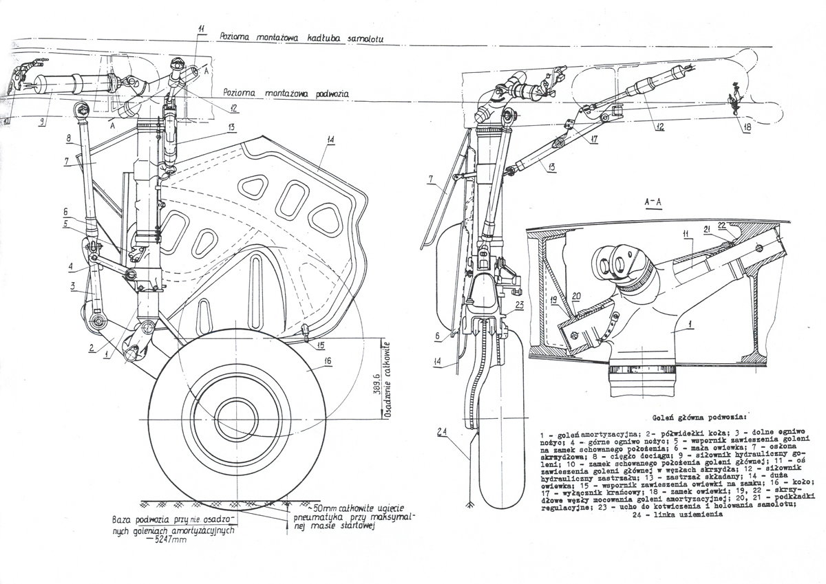
View of RHS main landing gear layout showing a basic trailing link arrangement, but with the pullrod ahead of the main strut. When the whole unit retracts into the wing, the pullrod swings the trailing link and wheel up toward the main strut. This is "shrink".
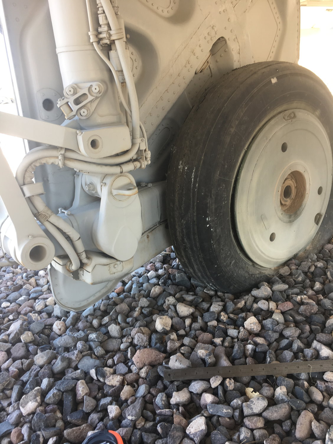
Pic of the RHS landing gear (fully compressed) on an Su-7, taken by Dave Evans (Ozie16) on RCU... Thanks!
The MLG uses a trailing link strut, basically. But it also uses a "pullrod" in front of the strut, that causes the trailing link/wheel unit to "shrink" against the strut, so that the MLG can be squeezed into a triangular bay inside the wings.
View of RHS main landing gear layout showing a basic trailing link arrangement, but with the pullrod ahead of the main strut. When the whole unit retracts into the wing, the pullrod swings the trailing link and wheel up toward the main strut. This is "shrink".
Pic of the RHS landing gear (fully compressed) on an Su-7, taken by Dave Evans (Ozie16) on RCU... Thanks!
The following users liked this post:
grbaker (06-18-2021)
06-14-2021, 02:37 PM
#4
It was going to take a while to figure out how to do the landing gear. It was decided I would start work on the Fuselage / Wing Plug designs, and hopefully a magical landing gear idea would eventually happen. The model scale would allow for something similar to an Electron E50 unit to be used, with modifications. The idea was not going to happen overnite, so I proceeded onto the the Plug design. I have a small 3D printer, that I've used a lot with ABS material. My machine is small enough that making fuselage cross sections was not going to be an option. I could get another larger machine, or just blend construction methods. In the end, I would have a laser cut service create basic fuselage bulkheads, and build a more typical fuselage of foam, glass, stringers, wrapped around a 2" steel hollow square post. Then, I would build additional detail with the 3d printer out of ABS plastic.
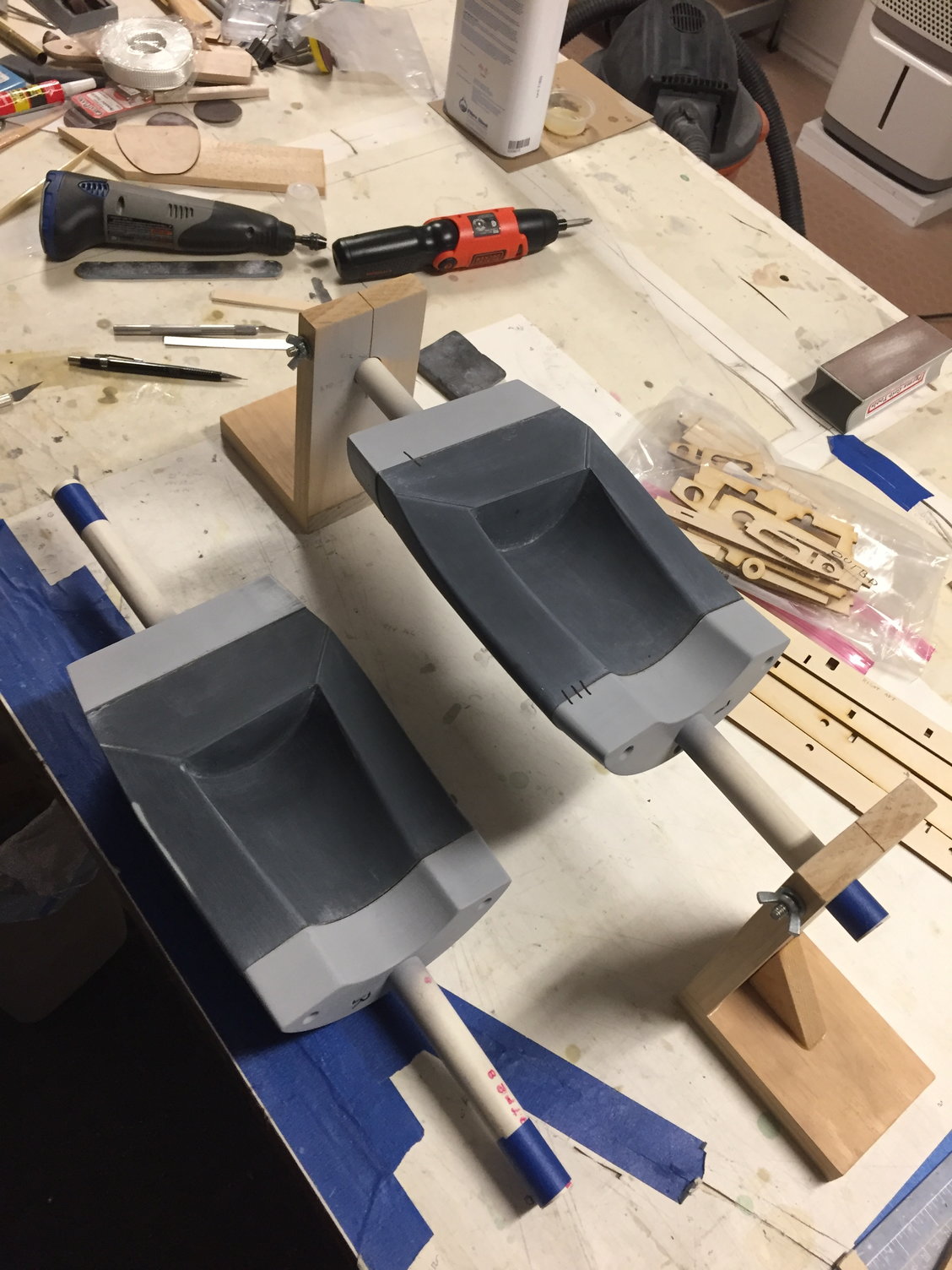
I would follow a similar path for the wings, but instead, I'd start with higher density foam cores that were glass sheeted... In the end, it was easier to make the plug shapes for the TE flaps, ailerons, slats, and other items with the 3d printer - everything was going to get glassed anyway, then bonded to the wing plugs or fuselage plugs as needed. Enclosed is a pic of the plug hardware showing the plug material makeup. The yellow printed parts represent hundreds of hours of growing time. I don't have a good number on that, because the effort on the project had to skip around between design and build continuously.
The ordering of the laser cut plug parts and first assembly is really when I see the physical portion of this task starting, which was November 2017 - I ordered the parts, then headed to the AZ Jet Rally.
Plug hardware was worked on until about July 2018, (where I was about 90% done).
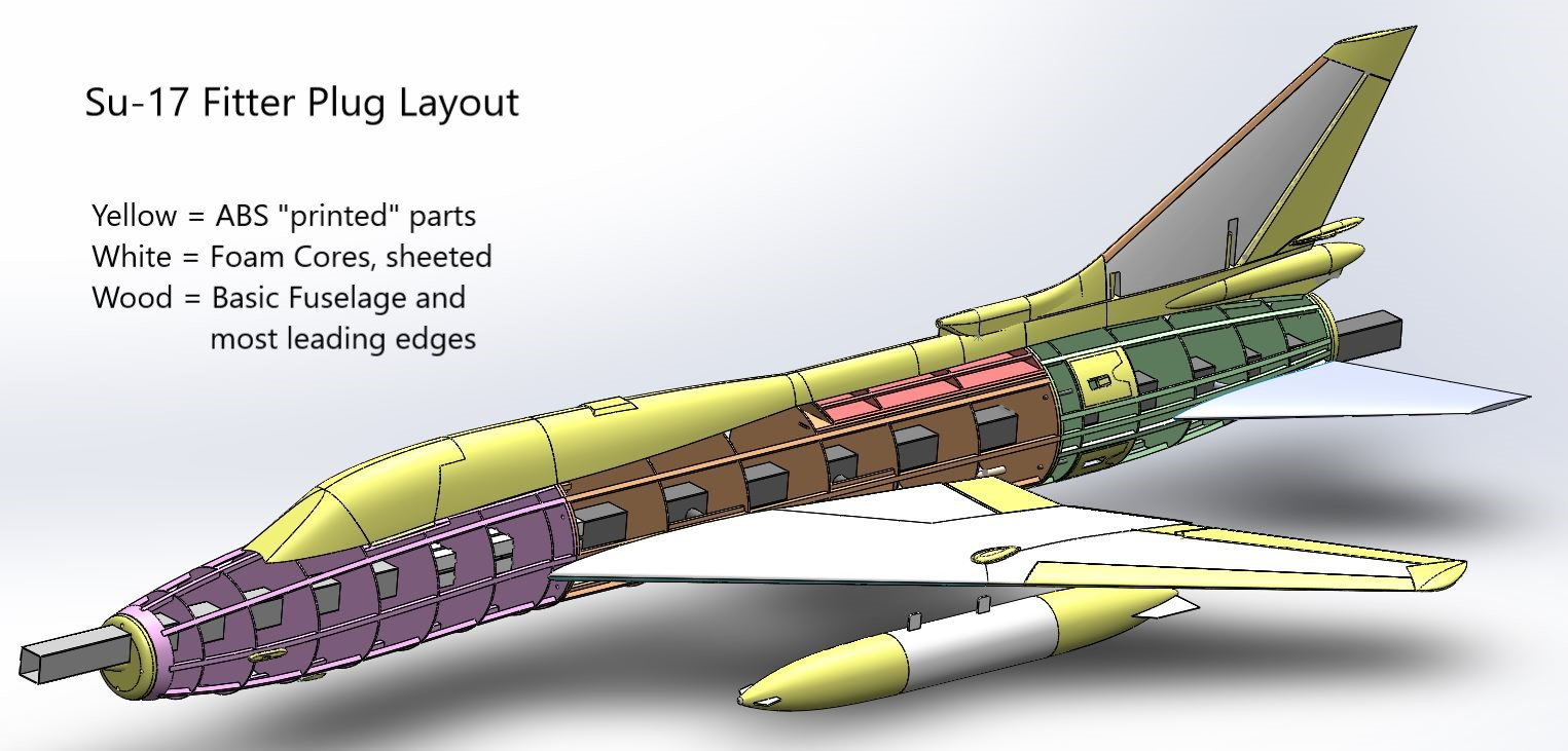
Plug material for the Su-17 model.
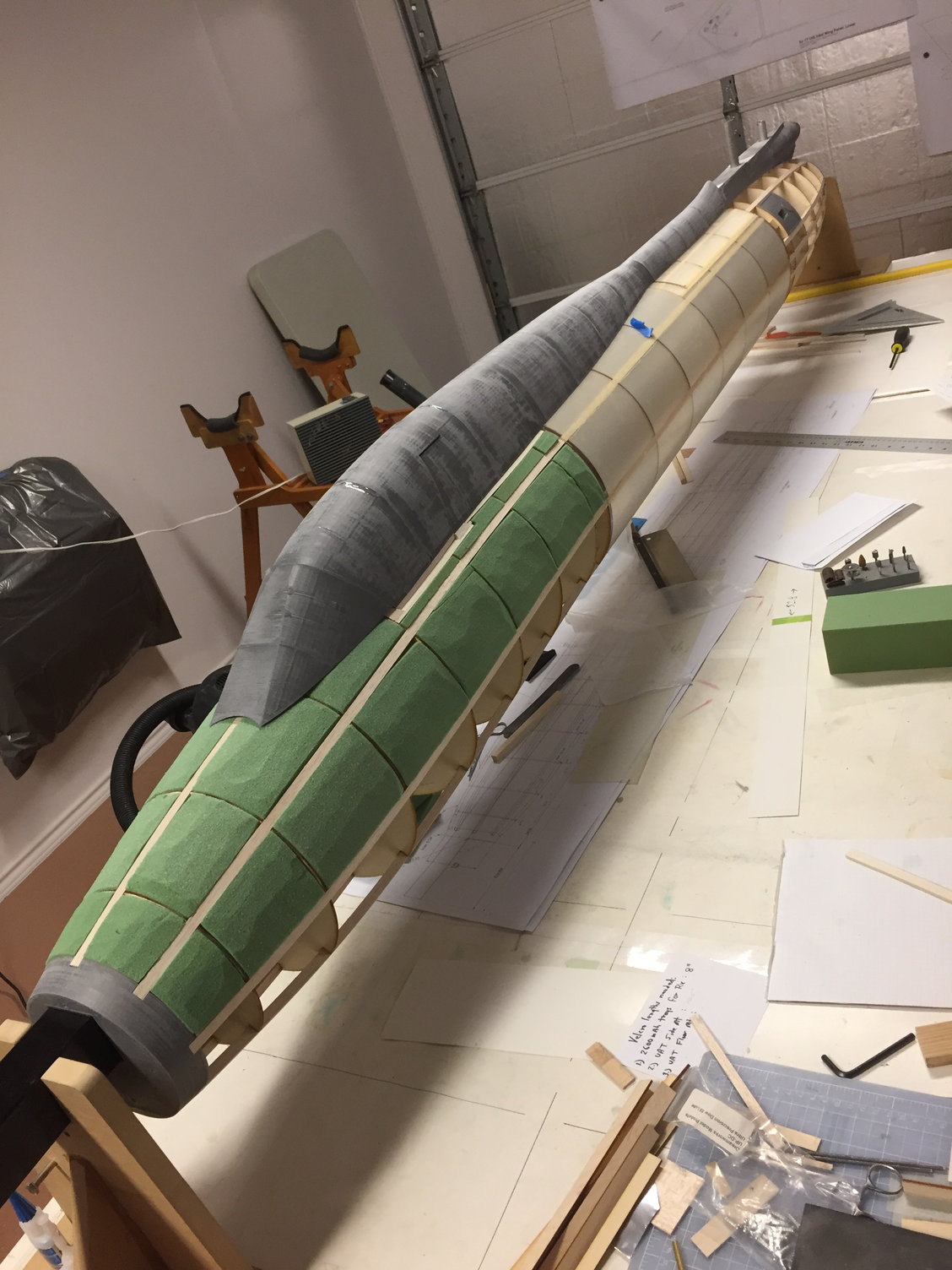
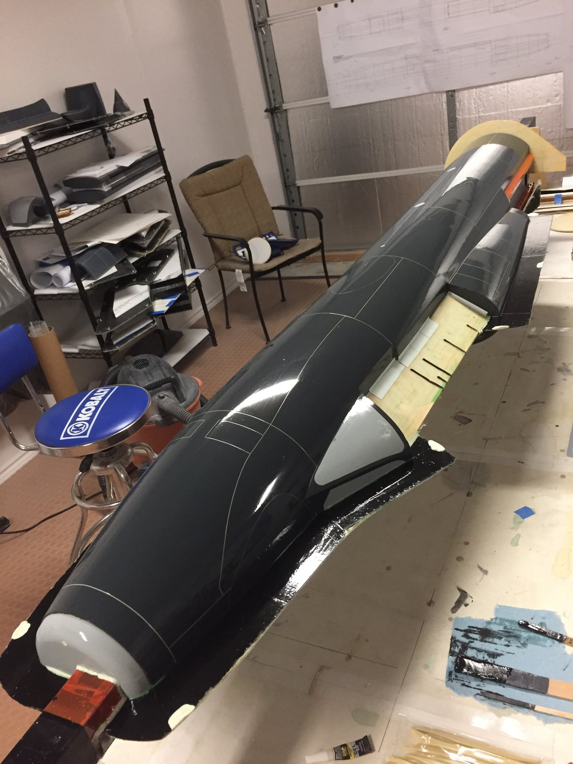
Early days on the fuselage plug
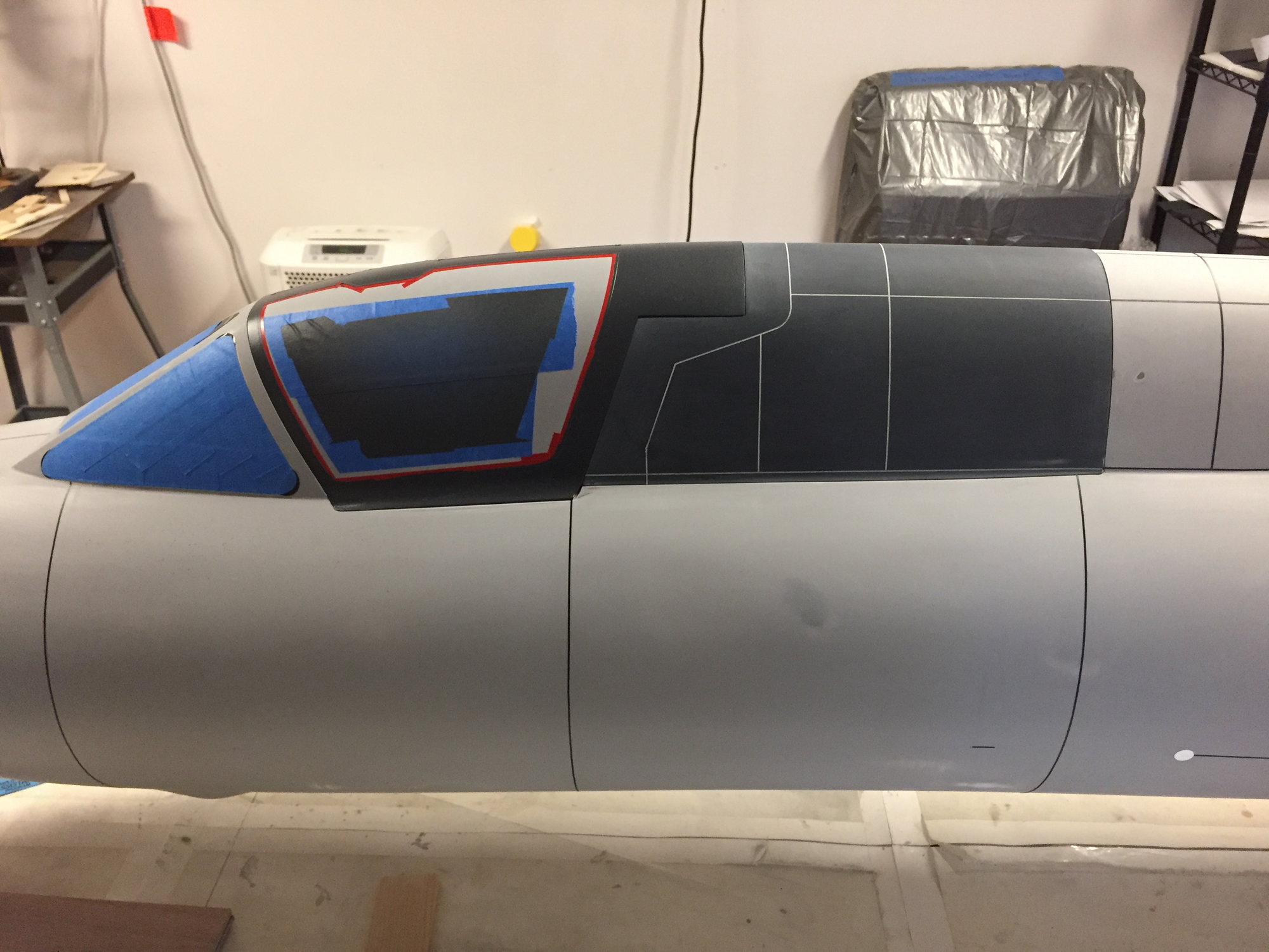
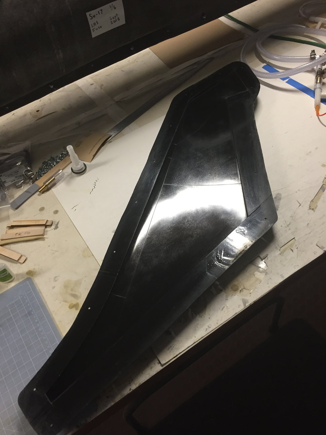
Blending canopy areas - older construction methods with some of the newer methods...
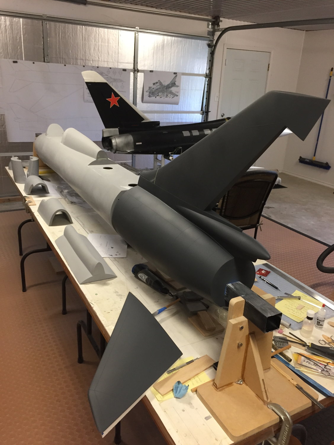
Tail surface plug parts. Never mind the Eurosport in the background. :-)
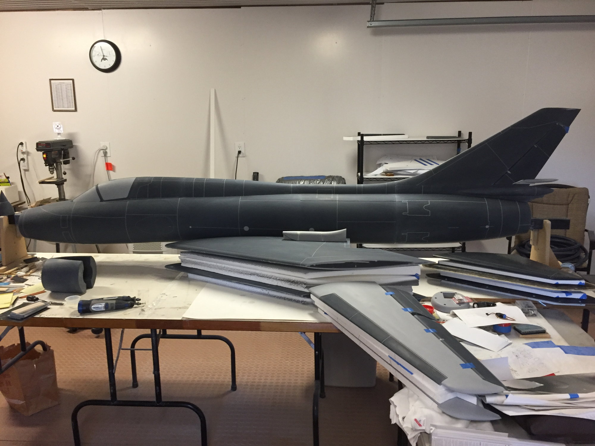
Plug hardware reaching the 90% point around July 2018.
I would follow a similar path for the wings, but instead, I'd start with higher density foam cores that were glass sheeted... In the end, it was easier to make the plug shapes for the TE flaps, ailerons, slats, and other items with the 3d printer - everything was going to get glassed anyway, then bonded to the wing plugs or fuselage plugs as needed. Enclosed is a pic of the plug hardware showing the plug material makeup. The yellow printed parts represent hundreds of hours of growing time. I don't have a good number on that, because the effort on the project had to skip around between design and build continuously.
The ordering of the laser cut plug parts and first assembly is really when I see the physical portion of this task starting, which was November 2017 - I ordered the parts, then headed to the AZ Jet Rally.
Plug hardware was worked on until about July 2018, (where I was about 90% done).
Plug material for the Su-17 model.
Early days on the fuselage plug
Blending canopy areas - older construction methods with some of the newer methods...
Tail surface plug parts. Never mind the Eurosport in the background. :-)
Plug hardware reaching the 90% point around July 2018.
Last edited by Ron S; 06-14-2021 at 02:41 PM. Reason: added pics
The following users liked this post:
grbaker (06-18-2021)
06-14-2021, 04:02 PM
#6

Ah! - the veil of secrecy has been lifted.
This is a spectacular build - even better in the 'flesh' than pictures can show. Ron's a craftsman and the attention to detail shows.
Well done Ron - a true Top Gun worthy model.
Let's see the rest of the build.
Paul
This is a spectacular build - even better in the 'flesh' than pictures can show. Ron's a craftsman and the attention to detail shows.
Well done Ron - a true Top Gun worthy model.
Let's see the rest of the build.
Paul
The following users liked this post:
yeahbaby (06-15-2021)
 06-14-2021, 05:21 PM
#8

Outstanding work.
Regards,
Regards,


 06-15-2021, 08:58 AM
#13
Thanks for all the nice comments. Sysiek, if you have any pics of your uncle's airplane, please feel free to post! My original plan was to do a Polish color scheme. Maybe for airplane 2. And the Eurosport is not mine - I did a minor repair job on it for a local friend. But now I know of this model's travels! ")
And Jetjon you went overboard a bit... But thanks!!
Sysiek, if you have any pics of your uncle's airplane, please feel free to post! My original plan was to do a Polish color scheme. Maybe for airplane 2. And the Eurosport is not mine - I did a minor repair job on it for a local friend. But now I know of this model's travels! And Jetjon you went overboard a bit... But thanks!!
Last edited by Ron S; 06-15-2021 at 08:59 AM. Reason: blushing
The following users liked this post:
jetjon (06-15-2021)
06-15-2021, 09:12 AM
#14
While building stuff, I was also trying to get sources for documentation. (well, searching for documentation started before laying out the model, but it was an ongoing thing) I'm still waiting for another book to ship, but my current collection of books include what's shown here, and a few model kits. Fyi, Kitty Hawk models recently announced they were closing their doors... 
I had also sent emails and made a couple calls to the Air Force Museum - it seems they have an Su-22M4 in their stash, but it is not on display. It would have been great to get actual measurements, but the museum (Public Affairs office) was not going to allow for any of that - a big thanks to them.
My hope initially was perhaps to make an overseas trip to do just that, or get better documentation at some point in time. That could still happen. Along with that though, there are several hundreds of pics and drawings online I've been able to download over the last few years. Plus, I borrowed Paul Stelly's Squadron book in the pic.
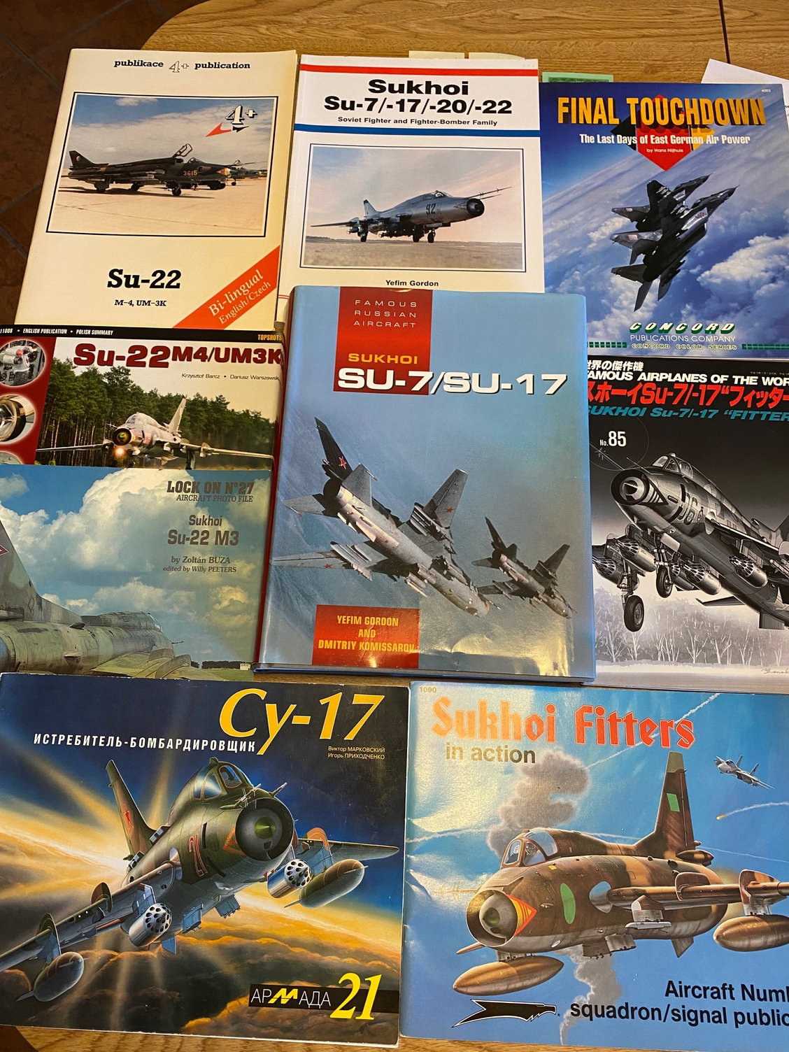
Books Galore...
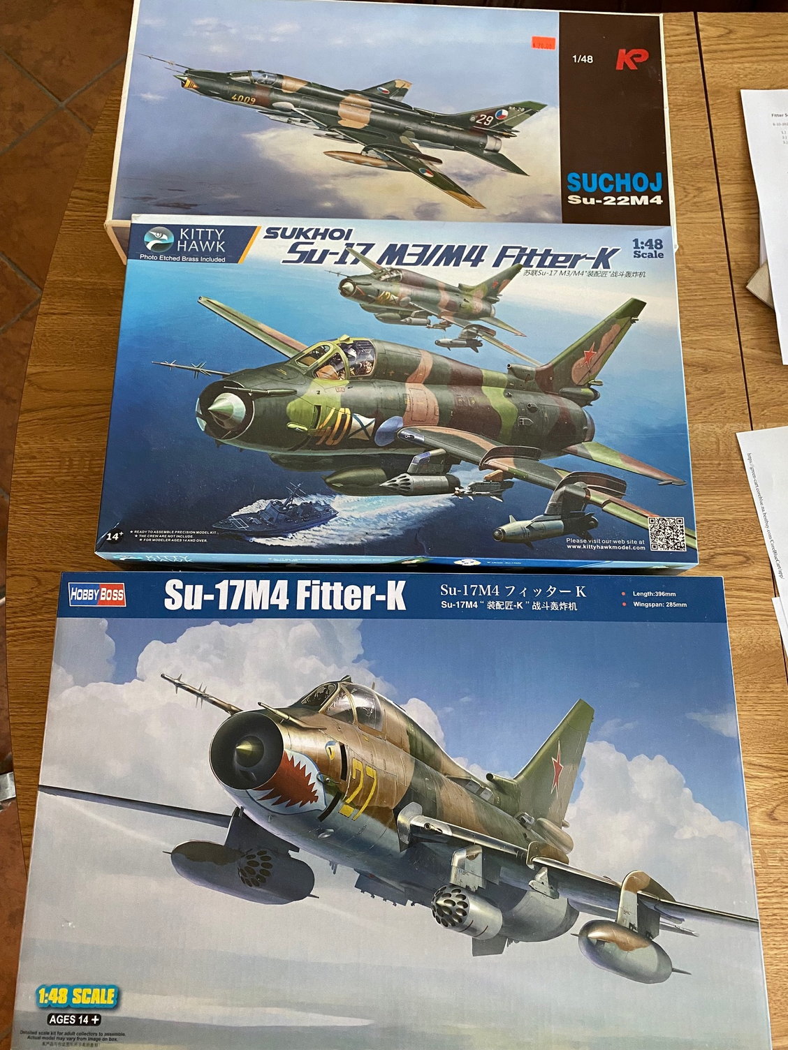
Didn't want to go overboard with the kits!...
I had also sent emails and made a couple calls to the Air Force Museum - it seems they have an Su-22M4 in their stash, but it is not on display. It would have been great to get actual measurements, but the museum (Public Affairs office) was not going to allow for any of that - a big thanks to them.
My hope initially was perhaps to make an overseas trip to do just that, or get better documentation at some point in time. That could still happen. Along with that though, there are several hundreds of pics and drawings online I've been able to download over the last few years. Plus, I borrowed Paul Stelly's Squadron book in the pic.
Books Galore...
Didn't want to go overboard with the kits!...
The following users liked this post:
grbaker (06-18-2021)
06-15-2021, 09:38 AM
#15
During Summer thru Fall of 2018 I worked on the molds. Or, atleast got to the 90% point. It always seems later down the road the decision is made to make more molds for the secondary parts (cockpit stuff, wheel liners, etc). When you get to this point, space starts becoming an issue (unless you are building inside a warehouse! ) A few mold pics below. They are not pretty - they're just a necessary evil...
Going thru my mold pics, I evidently did not keep many pics. They are hard to photograph because the insides are black gelcoat, and when I was in mold making mode, I didn't want to mess with my phone camera - its just finish a mold, then get onto the next.
I should also point out that most of the epoxy resin I used for the plug and molds were from Fibreglast in Ohio (System 2000). I've used them for a couple previous projects, and just felt it was easy to stick with them. On Paul B's Buccaneer project, he tried Duratec Primer for the Plug parts, and I had always wanted to try that, so I did this time around, and it seemed to work well. I also tried the same gelcoat Paul B used on his molds - I believe from ACP, and that worked well. I don't like working with the orange mold gelcoat that Fibreglast supplies - I just couldn't get used to that bright orange color.
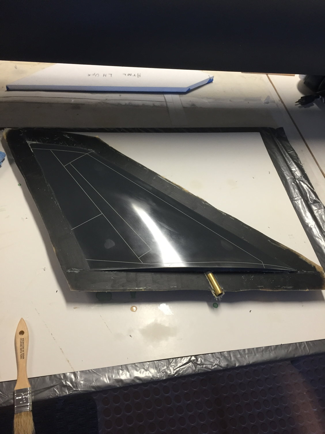
Htail mold in work.
Fuselage molds in work.
Inlet duct plugs being finished
Vertical fin mold half
) A few mold pics below. They are not pretty - they're just a necessary evil...Going thru my mold pics, I evidently did not keep many pics. They are hard to photograph because the insides are black gelcoat, and when I was in mold making mode, I didn't want to mess with my phone camera - its just finish a mold, then get onto the next.
I should also point out that most of the epoxy resin I used for the plug and molds were from Fibreglast in Ohio (System 2000). I've used them for a couple previous projects, and just felt it was easy to stick with them. On Paul B's Buccaneer project, he tried Duratec Primer for the Plug parts, and I had always wanted to try that, so I did this time around, and it seemed to work well. I also tried the same gelcoat Paul B used on his molds - I believe from ACP, and that worked well. I don't like working with the orange mold gelcoat that Fibreglast supplies - I just couldn't get used to that bright orange color.
Htail mold in work.
Fuselage molds in work.
Inlet duct plugs being finished
Vertical fin mold half
Last edited by Ron S; 06-15-2021 at 10:23 AM. Reason: speling errirs
06-15-2021, 09:57 AM
#16
The major mold work was finished (90%) around December 2018. Model design work continued, and I also developed a plan for the landing gear. Landing gear machining began in January 2019. Before that, I had ordered EV-50 retract sets from Electron. I had the smaller sets installed in my Pirotti Rebel and I thought they worked great, so I was willing to try the 50s this time around.
Actual model part design was also progressing - jumping between doing molds, working landing gear design, then back to model structure. Enclosed are a few Solidworks screen shots from late 2018 to early 2019.
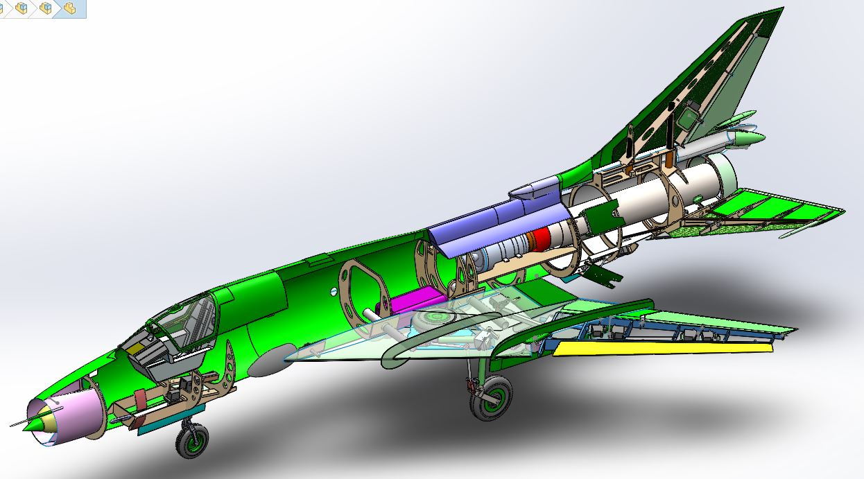
Early layout of the inside guts. :-)
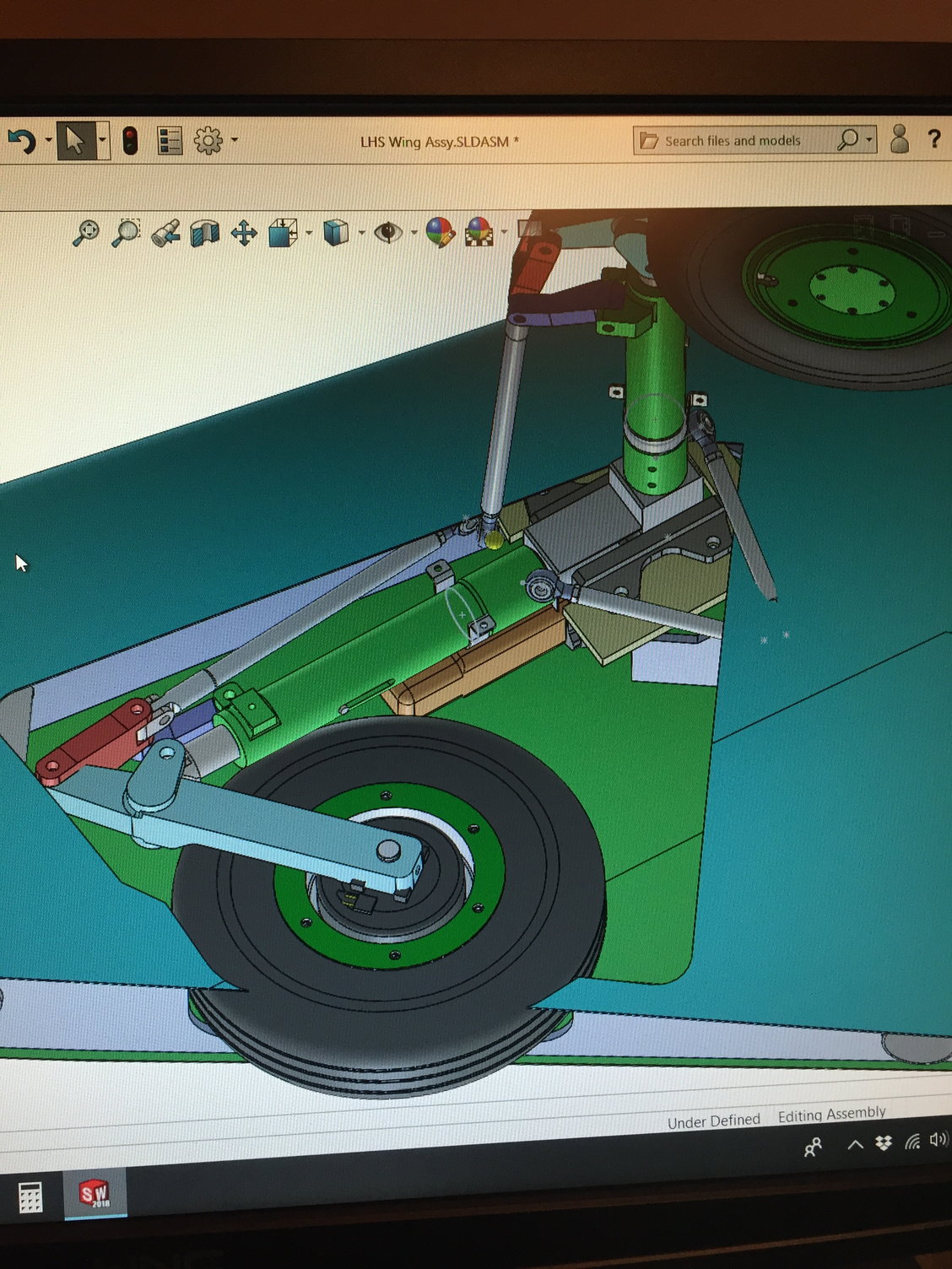
Prelim layout of the MLG. Electron EV-50s installed. The strut and wheel can fit into the MLG bay if I rotate the strut about its centerline axis. A yaw arm was added to do this. If I don't do this, commercial retract unit would not be usable - because the swing angle of the strut is angled in the planform and side views. the retract unit would be poking thru the top of the wing.
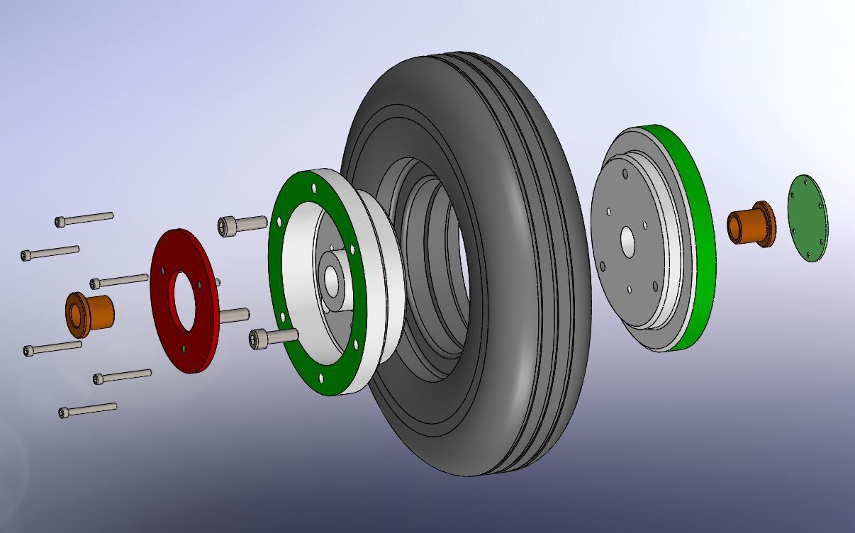
MLG wheel assembly. I could not find tires anywhere near the diameter I needed, so I was going to have to try casting them. Great...
Actual model part design was also progressing - jumping between doing molds, working landing gear design, then back to model structure. Enclosed are a few Solidworks screen shots from late 2018 to early 2019.
Early layout of the inside guts. :-)
Prelim layout of the MLG. Electron EV-50s installed. The strut and wheel can fit into the MLG bay if I rotate the strut about its centerline axis. A yaw arm was added to do this. If I don't do this, commercial retract unit would not be usable - because the swing angle of the strut is angled in the planform and side views. the retract unit would be poking thru the top of the wing.
MLG wheel assembly. I could not find tires anywhere near the diameter I needed, so I was going to have to try casting them. Great...
06-15-2021, 10:19 AM
#17
After the landing gear was modeled up in Solidworks, I grew the basic strut parts out of ABS plastic. I also grew a bagel sized tire shape, to eventually use as a plug for the whole tire casting experiment to be done. And I started machining some of the lathe "turned" parts for the NLG. I have a Small lathe, and am certainly not an expert with it, but I was going to try my best with it, and learn during the whole process. I do not have a mill, so any "flat machined" type parts I was going to have to make other arrangements.
Ultimate Jets actually had a perfect sized/shaped Behotec tire available for the NLG, so there was one success. I quickly ordered a few. For the next few months, I started making aluminum chips, ordering more bits and radius cutters, springs, and more aluminum stock. The Aluminum parts were from 7075-T6, and some of the less significant parts are 6061 (T3 I think) - whatever the common heat treat is. If I were to do it all over again, I'd just order nothing but 7075-T6.
At this point, I started describing this build in my JPO District VIII column of Contrails (~ February 2019).
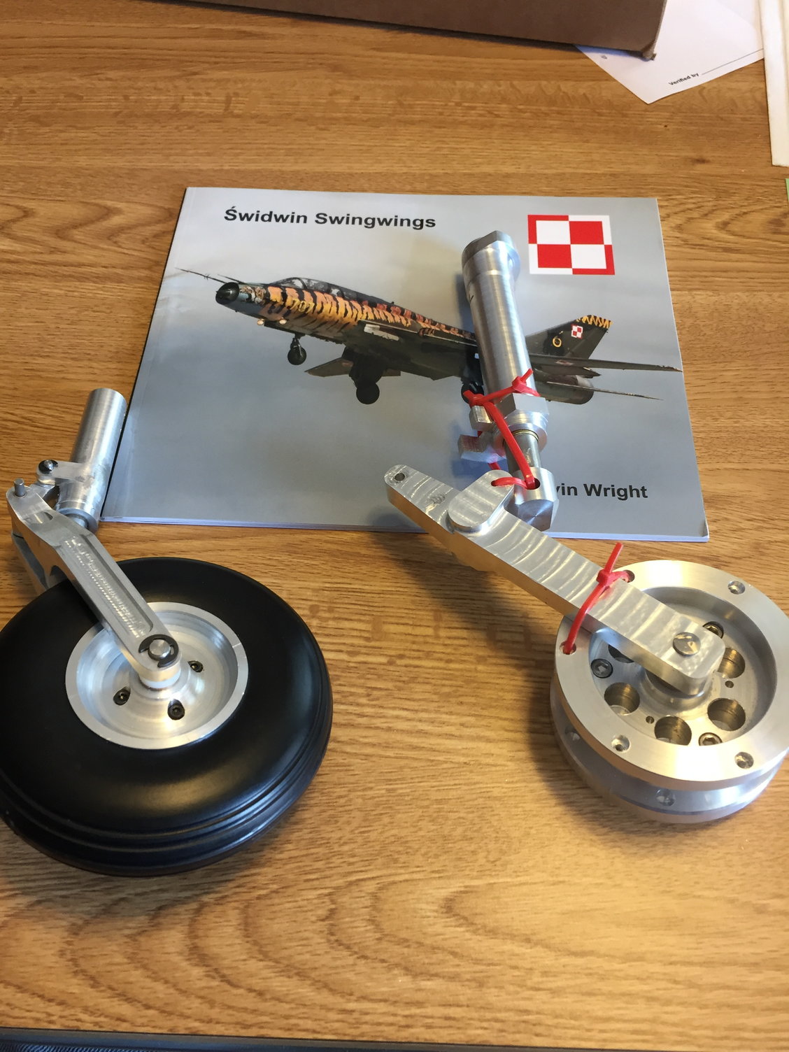
A NLG assembly, and the start of a MLG strut assembly.
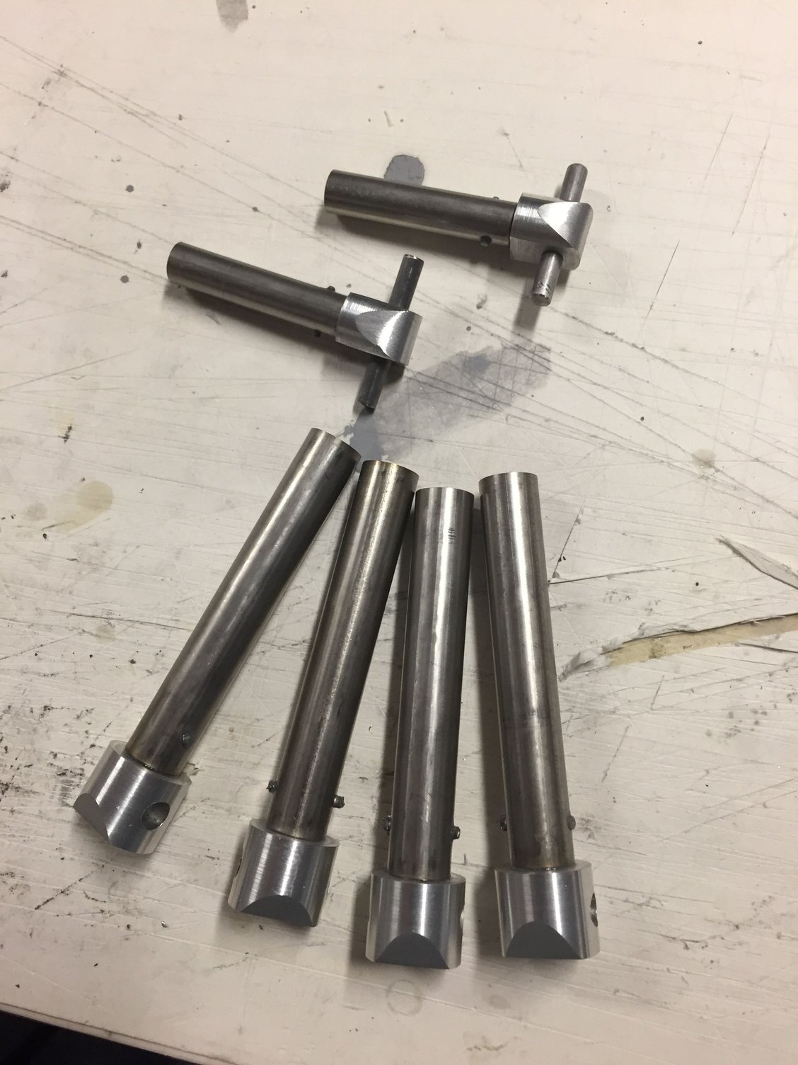
Lower strut assemblies, for the NLG and MLG - 2 sets.
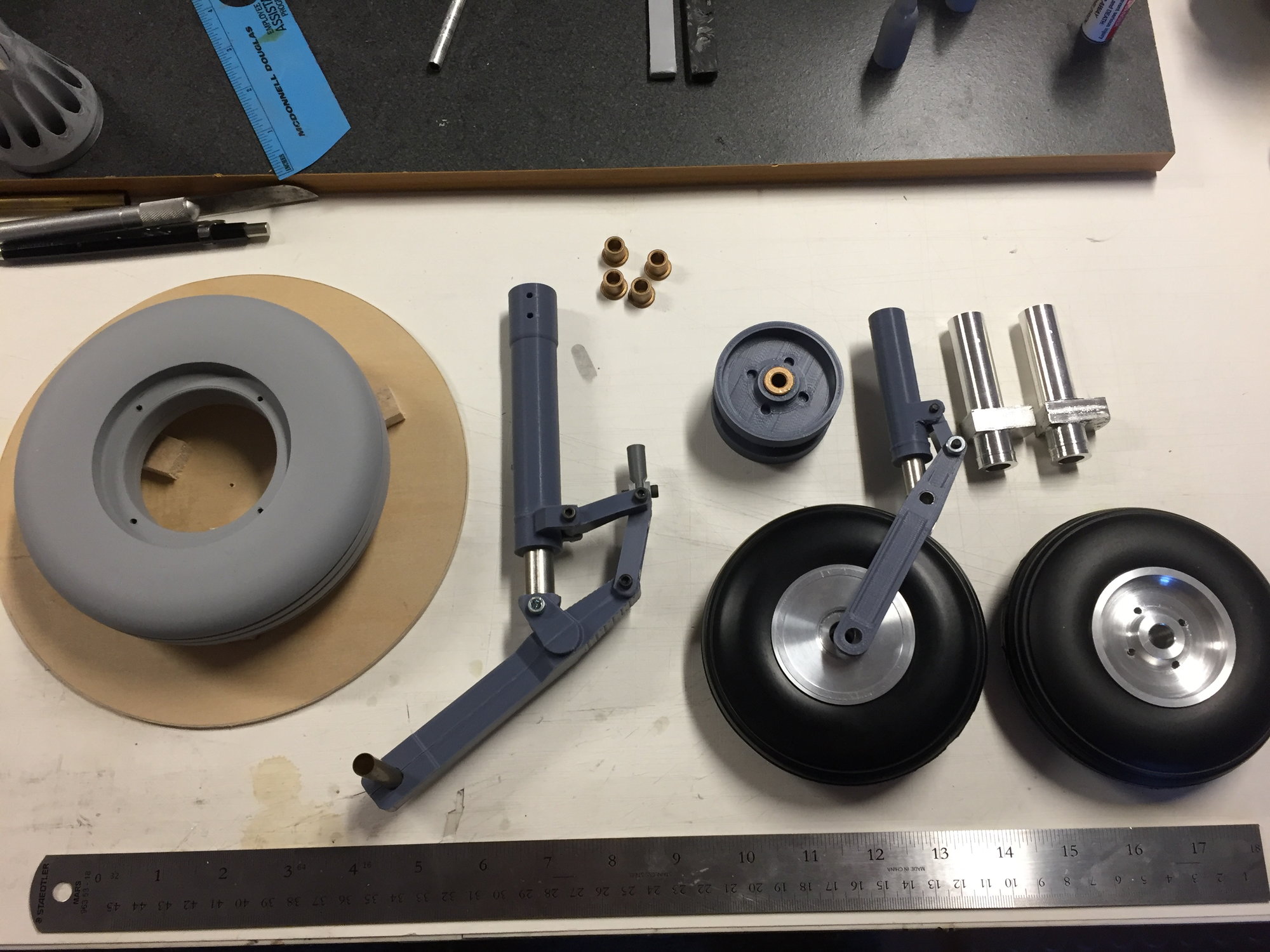
Plastic printed (grown) ABS struts, along with machined rims and the Behotec NLG tire. the plan was to make 2 usable landing gear sets for now.
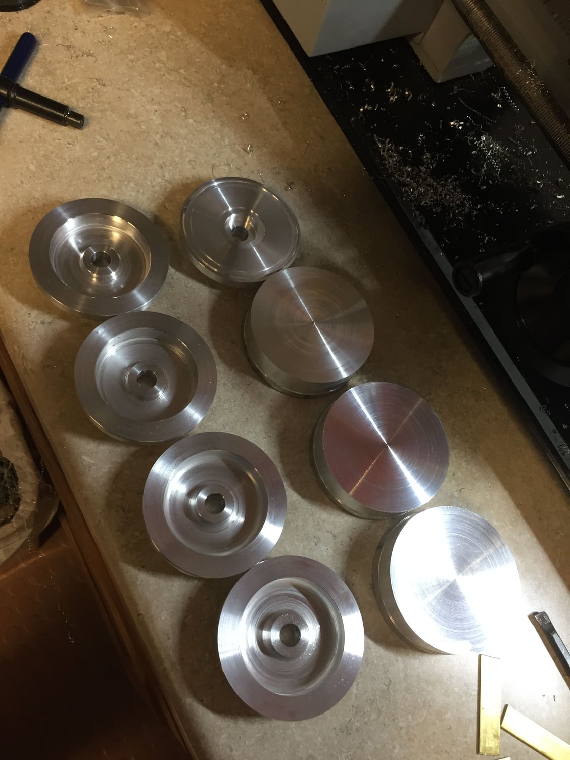
MLG or NLG rims in early stages of being turned on the lathe. Not even sure which is which right now. :-)
Ultimate Jets actually had a perfect sized/shaped Behotec tire available for the NLG, so there was one success.
I quickly ordered a few. For the next few months, I started making aluminum chips, ordering more bits and radius cutters, springs, and more aluminum stock. The Aluminum parts were from 7075-T6, and some of the less significant parts are 6061 (T3 I think) - whatever the common heat treat is. If I were to do it all over again, I'd just order nothing but 7075-T6.At this point, I started describing this build in my JPO District VIII column of Contrails (~ February 2019).
A NLG assembly, and the start of a MLG strut assembly.
Lower strut assemblies, for the NLG and MLG - 2 sets.
Plastic printed (grown) ABS struts, along with machined rims and the Behotec NLG tire. the plan was to make 2 usable landing gear sets for now.
MLG or NLG rims in early stages of being turned on the lathe. Not even sure which is which right now. :-)
The following users liked this post:
grbaker (06-18-2021)
06-15-2021, 10:48 AM
#18
I should also say, when I was trying to figure out the scale of the model, I also started a spreadsheet listing the component that makes up the model, and a best guesstimate of the weight of the item. I did this on my F-107A project from about a decade ago, and it worked pretty well. I wish I had done a better job (spent more time) approximating the weights - there were several items like wing fences, where, you'd think they would not contribute much to weight, but they would... When assembling the landing gear parts, it was evident I would be adding lightening holes into a lot of the chunky parts (rims, etc). Which is not a problem, but I would rather have designed more of that into the gear in the first place.
Also, anything having to do with pylons and stores, I did not keep in mind a contribution of weight to the list. Mainly because I figured If I get that far, I'd be ecstatic. Some of this project began with a bit of a "Ready, Shoot, Aim" attitude. I did not want to over analyze, then decide it could not be done...
Anyway, a 1/6 scale model would yield a size of about 112" length, and a span varying from 65 to 89 inches. I was shooting for 42-44 lbs dry. Always good to have a goal...
I will continue more postings tomorrow. Back to the model.
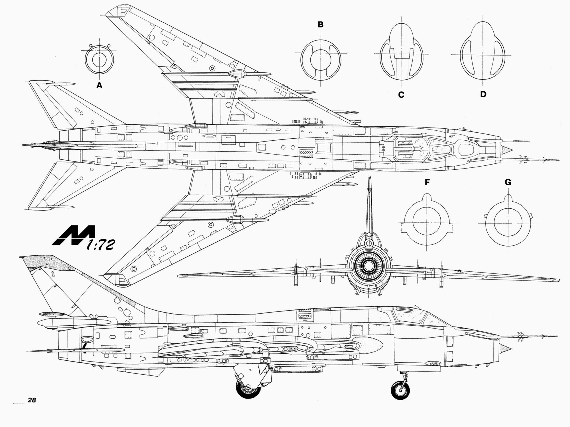
These are the 3 views I based the model on.
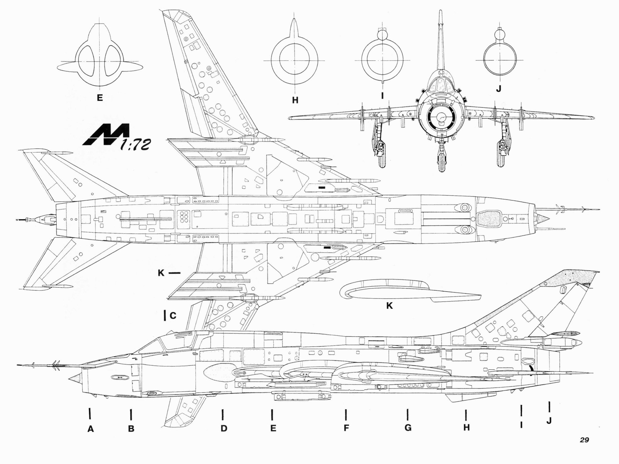
I was eventually able to find and purchase the book these 3-views came from, which is Armada #21, which evidently is a series of books similar to the Squadron book series in the US.
Also, anything having to do with pylons and stores, I did not keep in mind a contribution of weight to the list. Mainly because I figured If I get that far, I'd be ecstatic.
Some of this project began with a bit of a "Ready, Shoot, Aim" attitude. I did not want to over analyze, then decide it could not be done...Anyway, a 1/6 scale model would yield a size of about 112" length, and a span varying from 65 to 89 inches. I was shooting for 42-44 lbs dry. Always good to have a goal...
I will continue more postings tomorrow. Back to the model.
These are the 3 views I based the model on.
I was eventually able to find and purchase the book these 3-views came from, which is Armada #21, which evidently is a series of books similar to the Squadron book series in the US.
06-15-2021, 10:59 AM
#19
I remember visiting an air museum in phoenix (maybe Tucson but def AZ) with Ivan Munninghoff -was there for a jet meet and had the weird rainstorm. - they had a mig which had a similar strut to compress the gear during retraction, he passed the "rope" and was climbing into the wheel well to better understand the geometry. the 22 looks like it may have borrowed a bit from the mig 21, sounds like that part carried over as well.
06-15-2021, 12:12 PM
#20
Looking forward to the wing system, should be interesting.
Regards,
Regards,
06-15-2021, 06:11 PM
#22
Pat, if you visited the Pima Air Museum in Tucson with Ivan, I have pics of the MiG-21 there along with the Chinese J-6 a version of the MiG-19, which is somewhat a little bit like the Fitter MLG.
In the first MiG-21 pic, the strut is quite straight. It has a series of links that allow the wheel to stay parallel to the fuselage while it retracts into the fuselage.
In the MiG-19 or J-6 pic, this is the closest thing Pima has to the Fitter MLG gear. It does not have the shrink pullrod that is on the Fitter. I checked here - hoping I could find a Soviet aircraft that might have a similar arrangement. They do have a nice MiG-23 though, and I think my head would explode trying to figure out that arrangement!
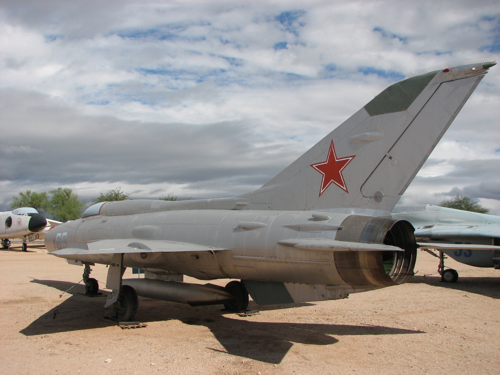
MiG-21PF at Pima air Museum
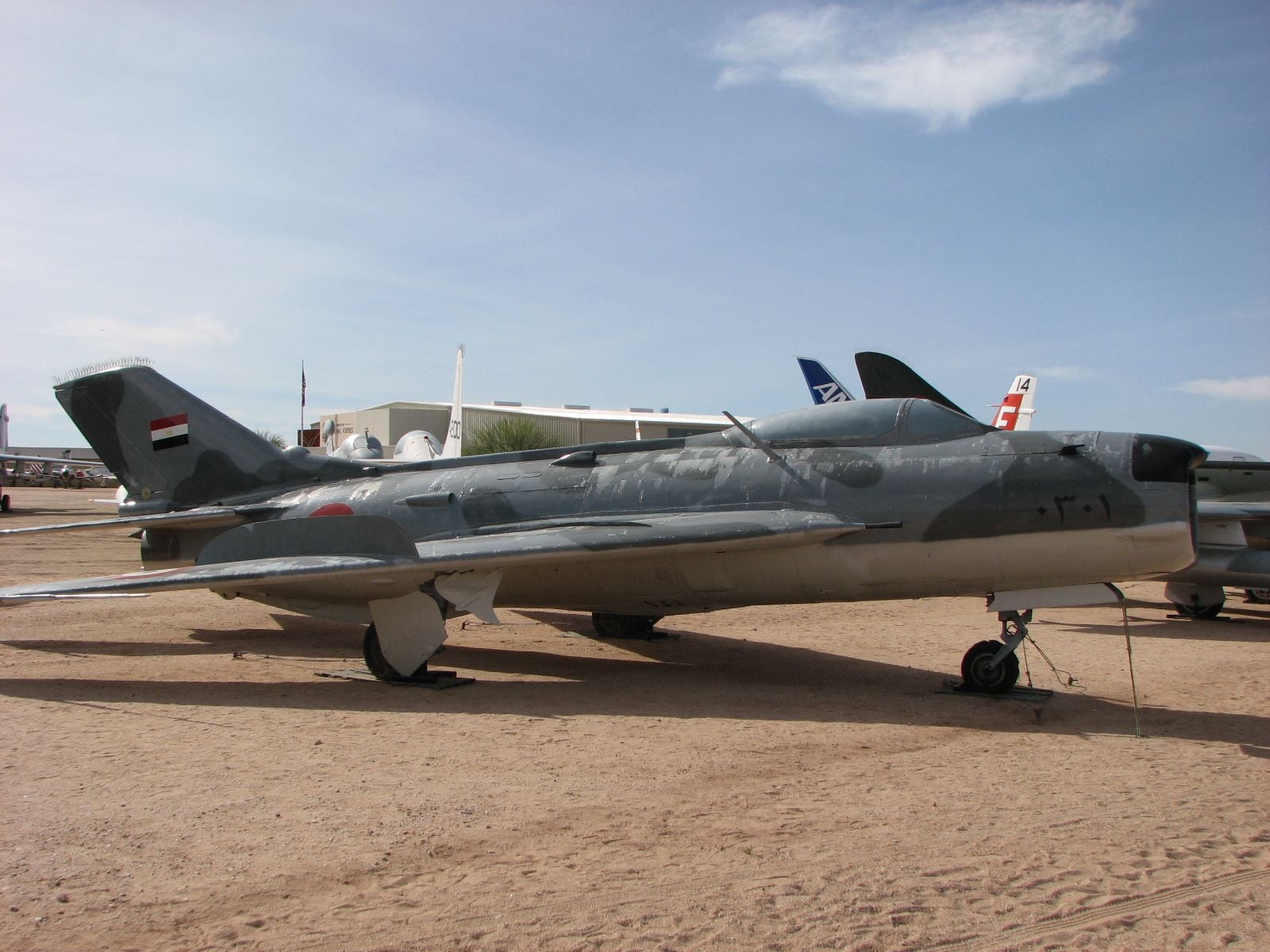
J-6 at Pima Air Museum
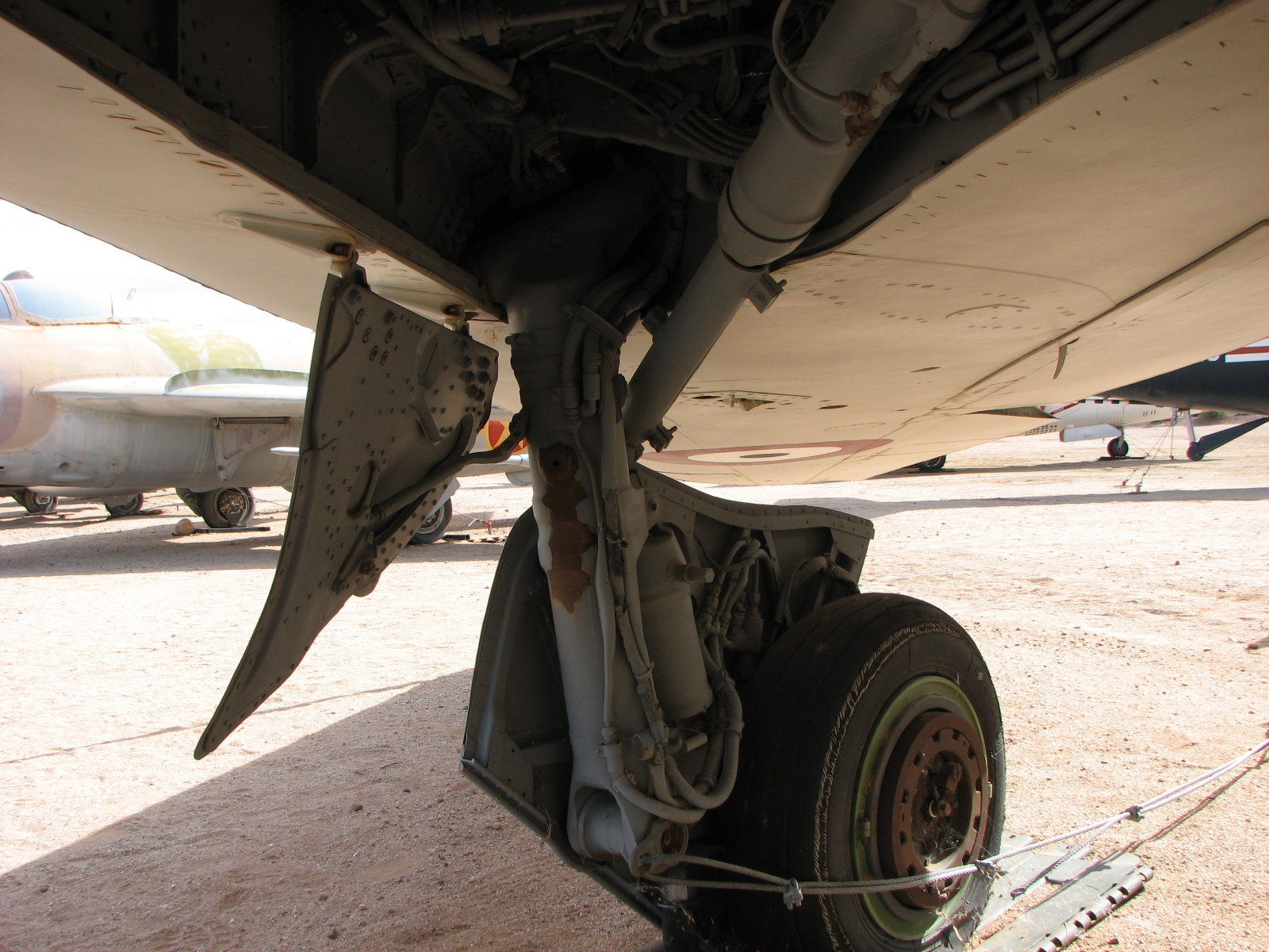
J-6 MLG. It is a trailing link strut arrangement, but there is no pullrod (ahead of the strut) to cause a shrink action while retracting.
In the first MiG-21 pic, the strut is quite straight. It has a series of links that allow the wheel to stay parallel to the fuselage while it retracts into the fuselage.
In the MiG-19 or J-6 pic, this is the closest thing Pima has to the Fitter MLG gear. It does not have the shrink pullrod that is on the Fitter. I checked here - hoping I could find a Soviet aircraft that might have a similar arrangement. They do have a nice MiG-23 though, and I think my head would explode trying to figure out that arrangement!
MiG-21PF at Pima air Museum
J-6 at Pima Air Museum
J-6 MLG. It is a trailing link strut arrangement, but there is no pullrod (ahead of the strut) to cause a shrink action while retracting.
The following users liked this post:
grbaker (06-18-2021)
06-16-2021, 04:35 AM
#23
Ron
I visited Pima when at the Tucson rally, this was a smaller indoor exhibit... that's why i think it was up at the phoenix rally. we also visited Aeroloft on that same trip. There is now a commemorative air force museum in Mesa, I wonder if that is the place. Same trip I drank four red bulls in an hour driving home and felt like i time travelled. so brain damage is not out of the question.
I visited Pima when at the Tucson rally, this was a smaller indoor exhibit... that's why i think it was up at the phoenix rally. we also visited Aeroloft on that same trip. There is now a commemorative air force museum in Mesa, I wonder if that is the place. Same trip I drank four red bulls in an hour driving home and felt like i time travelled. so brain damage is not out of the question.
06-16-2021, 03:17 PM
#24
I've been to the Commemorative AF museum too, and they have a 21 there I'm pretty sure. I'm not sure what else they have that might have similar gear - I'll have to check their website out.
I should also state in my last "goals" posting , that I was shooting for using around a 180 sized turbine. I can no longer edit that post.
I do intend on going through the wing stuff, but I'll probably post the build in order that the items were worked on. And that means I worked the aft fuselage stuff first. Htails, then Vtail, then Aft fuselage. Reason why is, I had not done this in a while (composite layups), and I figured if I have to scrap my first part or two, might as well be Htails, since they're not too involved. Luckily all went well.
The plan for basic construction of this model was to follow what I had done on an earlier project (same methods). i.e., Fiberglass skins with no backing foam, CF where I thought needed to improve stiffness, with the skins wrapped around lasercut structure. Also, I did not add rivet or fastener detail to the plug/molds, but I did apply most of the panel lines to the plug/molds. Some of the reasons for this: 1.) It would save a lot of up-front time, 2.) If I wanted to update the molds and add corrections, I could add them at a later date, 3.) I was not confident I could do an accurate job of applying that kind of minute detail to a model of an airplane I have not gotten my hands (or rulers) on, 4.) I felt it was more important to get the model in the air and focus on flyability before adding the minute detail, 5.) I can add much of that kind of detail to the model AFTER it has been built.
Also, I know many have had success with using the glass/foam/glass sandwich method. I have not experimented with that before. I suspect this method will create a stiffer laminate, but there will be a weight gain, and since the plies are not split onto either side of the foam, it seems one would get dings much easier into the outer glass ply (and pushing into the foam). So for now, no intents of using foam. But I do intend on making test panels at some point, for comparison...
I also have a scroll saw, but when it comes to cutting out bulkheads and ribs, I pretty much hate it. I don't have a laser cutter, but I have a friend that does. And he has a laser cutting service, and supplies the wood too. So I just have to get some of his wood, and get comfortable designing around it, then start sending him files for cutting. So Bob Leserve at www.laserdesignservices.com did all the cutting for me, for a very reasonable cost - I do appreciate the help!
The following users liked this post:
grbaker (06-18-2021)
06-16-2021, 03:36 PM
#25
Onto the Htails. Many Soviet aircraft have stabilators that have a SWEPT pivot axis. I just kinda assumed it was because you can cram the actuation hardware beneath the fuselage skin better, but now I suspect it is an attempt at moving the Htail pivot axis closer or aft of the aerodynamic center of the stabilator, hence a better chance at mass balancing the stabilator. If so, pretty clever, but it sure does make plug-in Htails more difficult. Mine will be removable if you have to, but for now I'm not designing that in as feature to make life easier... This is a prototype, and I'd rather save the weight.
So pics show the basic buildup of the Htail (screenshot), and the buildup process.
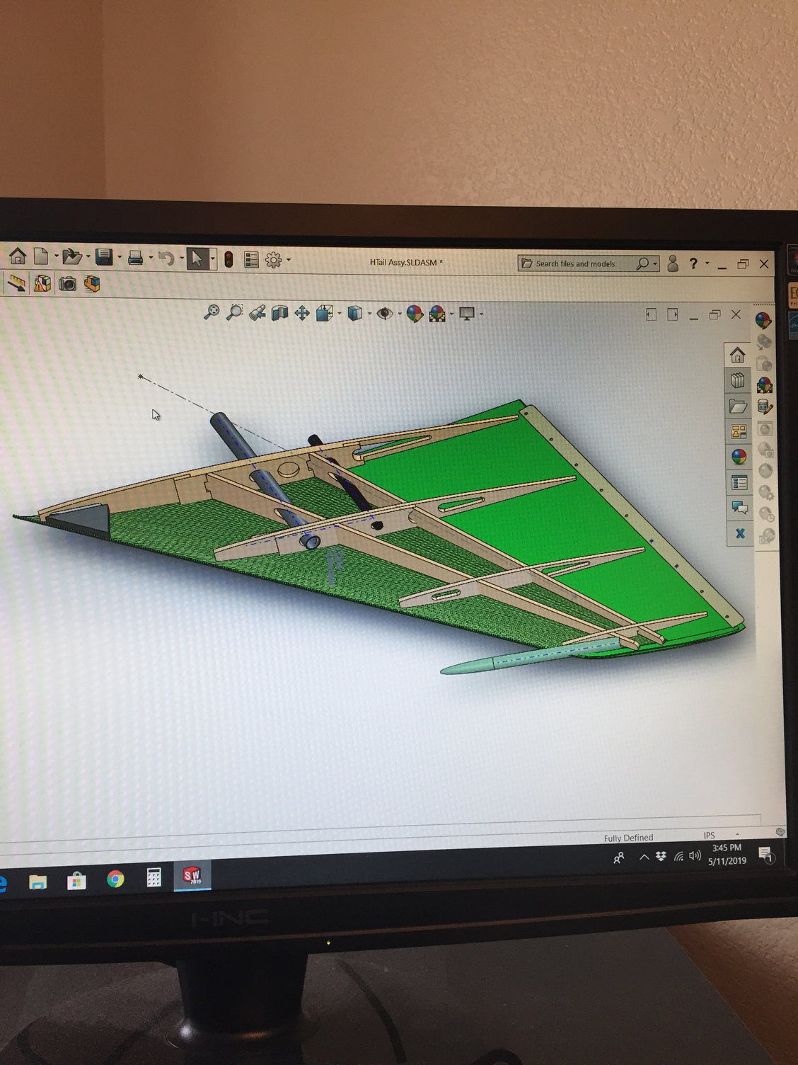
Screenshot of the Htail assembly.
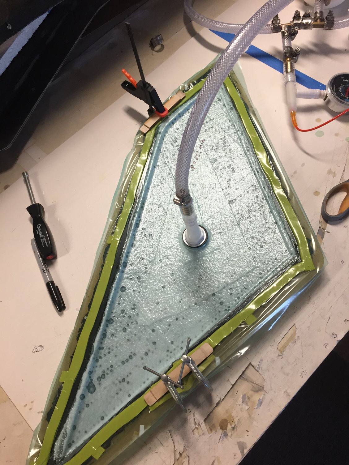
Vac bagging the Htail skins. Initially I tried using the method shown with yellow "dum-dum" tape sealant and single layer vacuum plastic sheet, but I could not keep good vacuum. After making the first 6-7 parts, I switched to using full bags going around the entire mold. Much easier to seal.
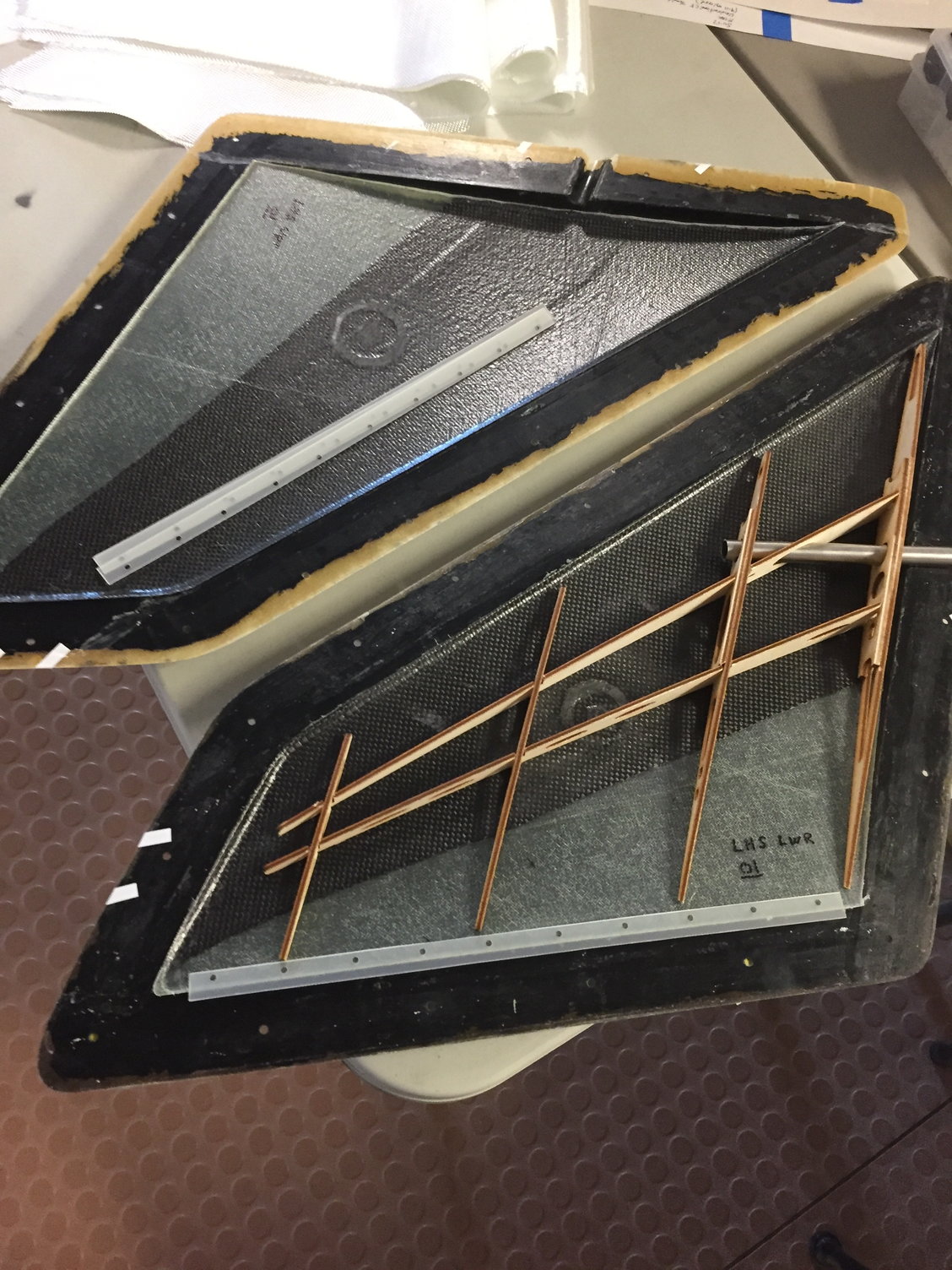
Trial fitting internal structure onto laid up and trimmed skins. You can see the first 2/3 of the skin with CF cloth... The part yielded a pretty stiff part in the end. I think I can remove some weight in future layups.
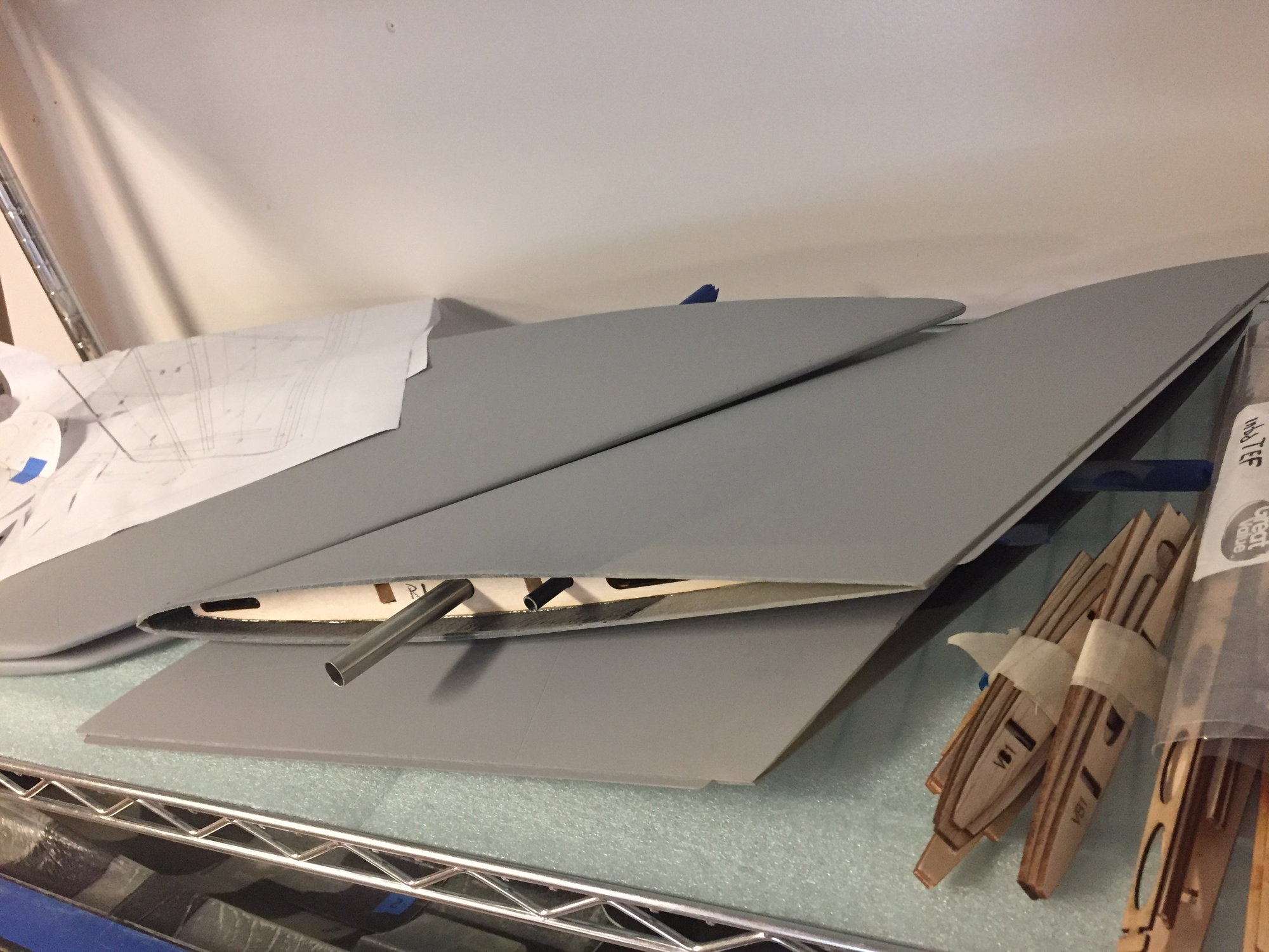
Parts eventually primed, then thrown onto the parts rack - move onto the next subassembly. More laser cut structure in waiting...
So pics show the basic buildup of the Htail (screenshot), and the buildup process.
Screenshot of the Htail assembly.
Vac bagging the Htail skins. Initially I tried using the method shown with yellow "dum-dum" tape sealant and single layer vacuum plastic sheet, but I could not keep good vacuum. After making the first 6-7 parts, I switched to using full bags going around the entire mold. Much easier to seal.
Trial fitting internal structure onto laid up and trimmed skins. You can see the first 2/3 of the skin with CF cloth... The part yielded a pretty stiff part in the end. I think I can remove some weight in future layups.
Parts eventually primed, then thrown onto the parts rack - move onto the next subassembly. More laser cut structure in waiting...
Last edited by Ron S; 06-16-2021 at 03:37 PM. Reason: added a word
The following users liked this post:
grbaker (06-18-2021)