


Assembler~Builder $
 10-02-2021, 04:27 AM
#26


Join Date: Dec 2011
Location: burlingtonontario, CANADA
Posts: 403
Likes: 0
Received 0 Likes
on
0 Posts
Assembly costs need to be broken down and offered in phases, 1) Assembled and hinged. 2) Landing gear and doors fitted. 3) Electrics, fuel, turbine and pipe fitted. 4) Primed. 5) Amount of external detailing 6) Simple paint work or custom weathering. 7) Cockpit simple or detailed. 8) Test flown and turn key.
 10-02-2021, 05:30 AM
#27
My Feedback: (1)
That was my point!!!! He looks to be trying to find cheap option to include with kit. This is unproven what the kit will even look like. I've built BVM from kits and you need 300 hrs minimum to complete a flyable plane. Many more hours depending on level of scale detail!!!
I hate the way everyone jumps to (YOUR WRONG CONCLUSION IN THIS FORUM)
10-02-2021, 04:08 PM
#28

My Feedback: (53)

That was my point!!!! He looks to be trying to find cheap option to include with kit. This is unproven what the kit will even look like. I've built BVM from kits and you need 300 hrs minimum to complete a flyable plane. Many more hours depending on level of scale detail!!!
I hate the way everyone jumps to (YOUR WRONG CONCLUSION IN THIS FORUM)
I hate the way everyone jumps to (YOUR WRONG CONCLUSION IN THIS FORUM)
 10-02-2021, 04:10 PM
#29

Hi Kevin,
Long time no see. I rarely get to Scobbe though I live only four miles away. We simply wanted to know what people were currently charging for "whatever" level of assembly. Post #2 defined the baseline product. This somehow created a dust storm. We anticipate three levels of product. Turnkey being a finished offering. Customer will specify JetFan or Sch�beler 110, 120, 130. Each inlet is 105% of 110 FSA. EDF is a customer install except turnkey.
Ed
Last edited by Flite-Metal; 10-02-2021 at 04:26 PM.
 10-03-2021, 01:14 PM
#32

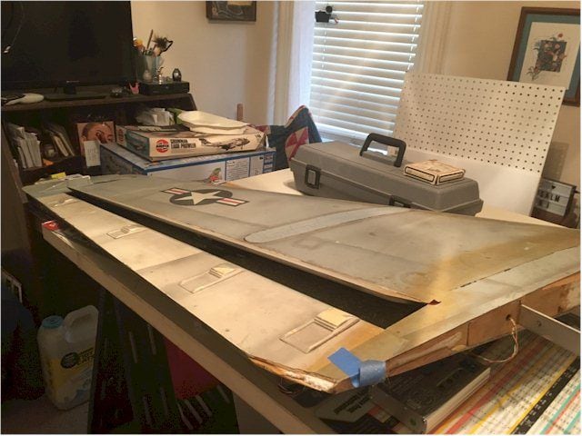
This is where the actual assembly aspect of these four 6's were showcased in the design thread. I suppose a few simple illustrations will serve to show prefab aspects of the design. To understand this you have to look back in this thread and the design threads.

Foam core slat, wing, solid spoileron, and core flap. Simply sheeted and hinged. Internal slat structure is prefab with proportional movement with the flap. Foam cores are hot wired to fit coves without the builder/assembler having to do more than sheet the surfaces.

Foam core slat, wing, solid spoileron, and core flap. Simply sheeted and hinged. Internal slat structure is prefab with proportional movement with the flap. Foam cores are hot wired to fit coves without the builder/assembler having to do more than sheet the surfaces.
Lastly, your depiction of the flaps may create a challenge for potential scale customers. Per the NATOPS manual, "The wing flaps are semi-Fowler type slotted flaps..." - not the split flaps shown in the diagram.
Hope this helps you. With a few thousand hours in this A6 series, I look forward to seeing this project fly.
10-03-2021, 03:20 PM
#33
Franklin,
Thank you for your post. All help is appreciated.:
However...
Spoileron: While it is true NAVAIR 01-85ADA-1(1-45) refers to spoilerons as flaperons. All branches of the service tend to name/rename aerodynamic devices and functions to make it their own. Clicking Spoileron will link you to the aeronautical definition of that word/function.
Flaperon: Flaps which function through “X” % of the aileron movement. On the B-47 flaperon function in unison with the aileron until the aileron exceeds 25% of travel.
Deceleron: Are devices originally intended to aid in roll control as well as reduce airspeed during final descent, Decelerons are typically located at or near wing tips due to the lack of available space elsewhere. We provide information for acrivating the decelerons. That area of the wing is a vacuum formed piece included with each model. We chose to not design in the deceleron due to someone could literally stall during the approach...aka crash. However functionality could be achieved if coupled to the electric brakes upon touchdown..
.
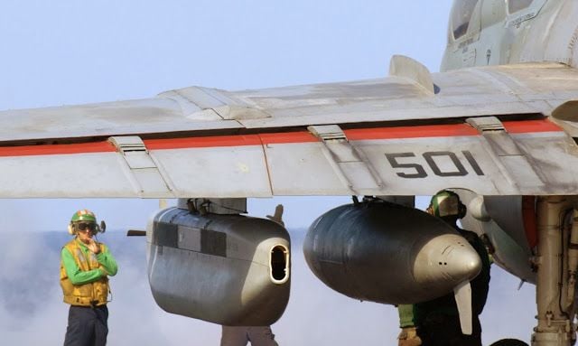
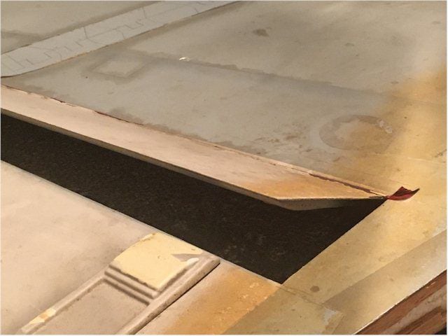
Flaps on the MAC6's are not extended trusses as found in the Fowler flap. Viewed from the top the MAC6's give the visual illusion of the Grumman A6 trusses ahead of each telescoping truss. The 1:1 A6 flap leading edge is painted red because it is a pinch zone hazard...and is visible when the flaps are deployed. If we were to replicate the Fowler flap truss...believe me we tried several configurations...it was judged to not be practical or safe..
Because the leading edge of the flap is exposed...its red surface contributes to an illusion the flap has moved rearward as it is lowered. The 1:1 image below looks the same as our flaps do.
Thank you for your post. All help is appreciated.:
However...
Spoileron: While it is true NAVAIR 01-85ADA-1(1-45) refers to spoilerons as flaperons. All branches of the service tend to name/rename aerodynamic devices and functions to make it their own. Clicking Spoileron will link you to the aeronautical definition of that word/function.
Flaperon: Flaps which function through “X” % of the aileron movement. On the B-47 flaperon function in unison with the aileron until the aileron exceeds 25% of travel.
Deceleron: Are devices originally intended to aid in roll control as well as reduce airspeed during final descent, Decelerons are typically located at or near wing tips due to the lack of available space elsewhere. We provide information for acrivating the decelerons. That area of the wing is a vacuum formed piece included with each model. We chose to not design in the deceleron due to someone could literally stall during the approach...aka crash. However functionality could be achieved if coupled to the electric brakes upon touchdown..
.
Flaps on the MAC6's are not extended trusses as found in the Fowler flap. Viewed from the top the MAC6's give the visual illusion of the Grumman A6 trusses ahead of each telescoping truss. The 1:1 A6 flap leading edge is painted red because it is a pinch zone hazard...and is visible when the flaps are deployed. If we were to replicate the Fowler flap truss...believe me we tried several configurations...it was judged to not be practical or safe..
Because the leading edge of the flap is exposed...its red surface contributes to an illusion the flap has moved rearward as it is lowered. The 1:1 image below looks the same as our flaps do.
.
 ..
..
..Last edited by Flite-Metal; 10-03-2021 at 04:12 PM.
10-03-2021, 04:38 PM
#34

You could build a simplified wing for your first model - minimize the bells and whistles on the first wing - to help with your build schedule, keep it lighter, etc. Then prove out the rest of the airframe, Cg, etc.
Then later, build a second wing with one or more additional functions (slats, or wingtip speedbrakes (decelerons), etc ). Since there's no landing gear details that interact with the wing... Then, if you run into unexpected slat difficulties (for example), it doesn't kill the remainder of the project. Just a suggestion.
Then later, build a second wing with one or more additional functions (slats, or wingtip speedbrakes (decelerons), etc ). Since there's no landing gear details that interact with the wing... Then, if you run into unexpected slat difficulties (for example), it doesn't kill the remainder of the project. Just a suggestion.
The following users liked this post:
FalconWings (10-04-2021)
10-03-2021, 05:25 PM
#35
You could build a simplified wing for your first model - minimize the bells and whistles on the first wing - to help with your build schedule, keep it lighter, etc. Then prove out the rest of the airframe, Cg, etc.
Then later, build a second wing with one or more additional functions (slats, or wingtip speedbrakes (decelerons), etc ). Since there's no landing gear details that interact with the wing... Then, if you run into unexpected slat difficulties (for example), it doesn't kill the remainder of the project. Just a suggestion.
Then later, build a second wing with one or more additional functions (slats, or wingtip speedbrakes (decelerons), etc ). Since there's no landing gear details that interact with the wing... Then, if you run into unexpected slat difficulties (for example), it doesn't kill the remainder of the project. Just a suggestion.
Not doing deceleron in first 6 so that saves a ton of time. Slats and activation frames (4) are in the foam wing cut so I may only do spoileron on #1. There is no air system. A retract, retract door, and brake controller simplifies radio setup and wiring in fuse. I am not cutting canopy frame nor installing cockpit tub on #1.
Last edited by Flite-Metal; 10-04-2021 at 04:32 AM.
10-04-2021, 05:23 AM
#37
My Feedback: (19)
The amount of work these are going to take will be a tough sell these days. Not very many people take on a huge build project like these anymore. Honestly, the amount of time and skill needed for this, I would look at what full scale homebuilt services charge.
The following users liked this post:
mikes68charger (10-08-2021)
10-04-2021, 07:03 AM
#38
My Feedback: (53)
I agree, especially this is for an EDF jet (not saying it�s bad) but that�s a lot of money for an EDF, so I see this more as a self build and not paying thousand to get it done�..Unlike turbine models�
10-04-2021, 09:11 AM
#39
Thank you for asking.
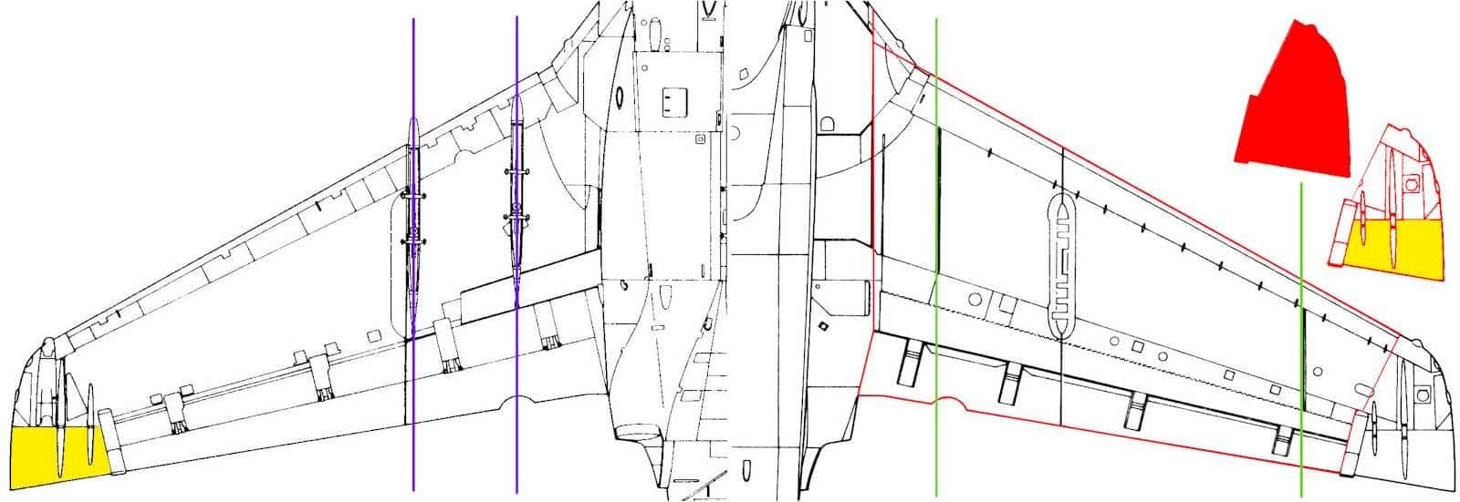
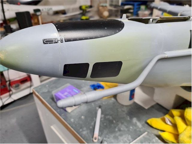
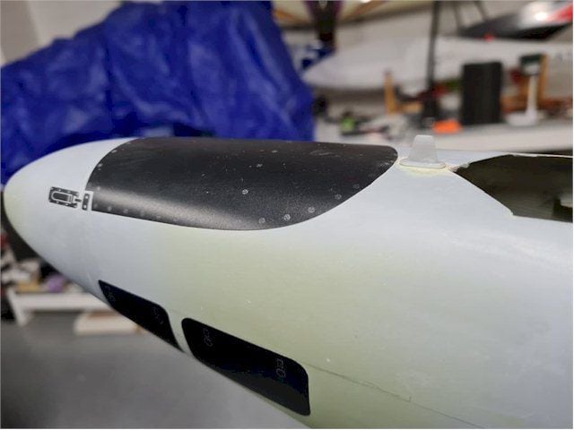
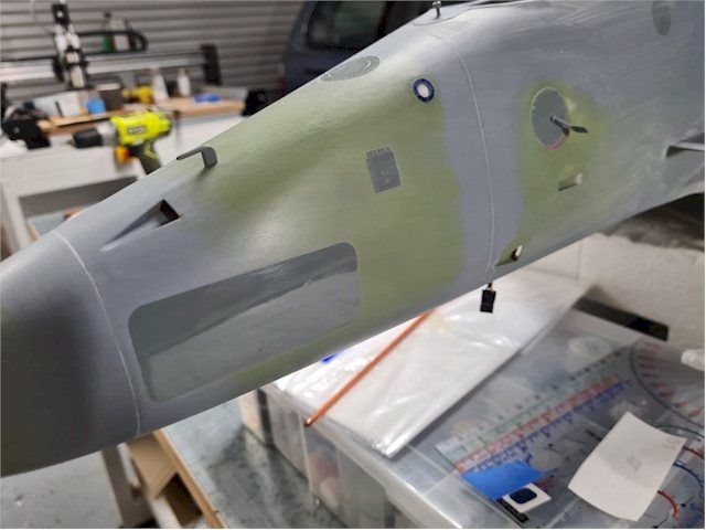
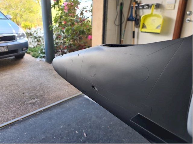
Answering your initial question...The one piece movie fuselage utilized as the plug for our upgrading to a two piece fuselage had no panel line definition. Panels on the 8 movie A6's were painted on. Below are a few pics of the movie 6's left wing top. Below pics I will continue to explain surface details on the MAC6's.
.
.
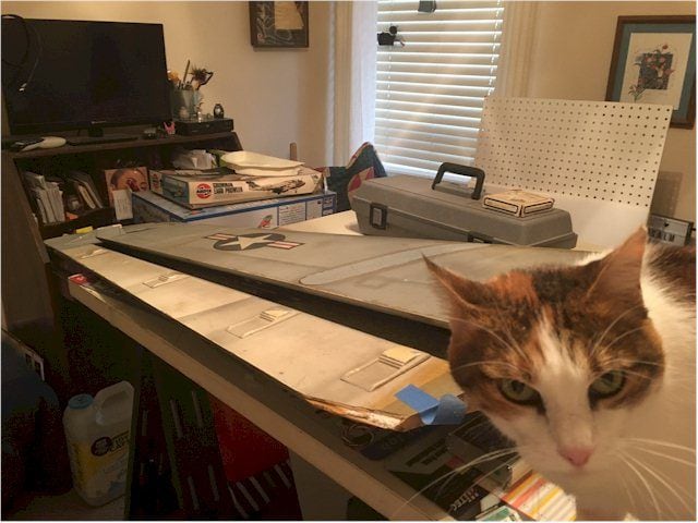
My hel-purrrr.
My hel-purrrr.
Last edited by Flite-Metal; 10-04-2021 at 10:50 AM.
10-04-2021, 11:08 AM
#40
Thank you for your post. All help is appreciated ... However...
Spoileron: While it is true NAVAIR 01-85ADA-1(1-45) refers to spoilerons as flaperons. All branches of the service tend to name/rename aerodynamic devices and functions to make it their own. Clicking Spoileron will link you to the aeronautical definition of that word/function.
Flaperon: Flaps which function through “X” % of the aileron movement. On the B-47 flaperon function in unison with the aileron until the aileron exceeds 25% of travel.
Deceleron: Are devices originally intended to aid in roll control as well as reduce airspeed during final descent, Decelerons are typically located at or near wing tips due to the lack of available space elsewhere. We provide information for acrivating the decelerons. That area of the wing is a vacuum formed piece included with each model. We chose to not design in the deceleron due to someone could literally stall during the approach...aka crash. However functionality could be achieved if coupled to the electric brakes upon touchdown..
The 1:1 A6 flap leading edge is painted red because it is a pinch zone hazard.../QUOTE]
The red has nothing to do with pinch points. The surface underneath is red so that if they're partially extended or not fully retracted there's significant contrasting color that's easily visible from the cockpit or from another aircraft flying in formation. Could it have been blue or black instead? Sure, but the Navy chose red. It has nothing to do with pinch points.
QUOTE=Flite-Metal;12696995]Because the leading edge of the flap is exposed...its red surface contributes to an illusion the flap has moved rearward as it is lowered. The 1:1 image below looks the same as our flaps do.
I really don't know why you are so intent on ignoring what the actual flight manual says or someone with over 2,000 hours actually flying the aircraft tell you about how the flaps work. If nothing else, I'd think it hurts you with potential customers, but if you want to cling to inaccurate word choice and ideas about the flight surfaces work, then go ahead. It's your credibility that gets damaged.
Last edited by franklin_m; 10-04-2021 at 11:49 AM.
10-04-2021, 12:11 PM
#41
On the A6 series, they're called flapersons and speed brakes. I clicked on your "deceleron" link, and note that in the wikipedia article, which is hardly authoritative when it comes to nomenclature of a specific aircraft, only one of them was even related to a military source. And one does not make the argument. I'm struggling to understand why you're so wedded to nomenclature that is NOT reflected in the actual flight manual for the aircraft you're modeling.
I have no idea where you ever got the impression they were used to control roll. Not on this aircraft, which is probably why the manual calls them "speed brakes." There is no differential deployment of the speed brakes on the actual aircraft. In fact, it's an emergency situation if they do (that means it's not supposed to happen). Having actually flown the actual aircraft, they extend and retract in unison on the top and bottom of the wing. They are not used for roll control. Also, please explain how the speed brakes cause a stall. They add drag - period. They're no different in that sense than extending the landing gear. If you didn't include them for simplicity purposes, that's fine, but they have no effect on stall speed (at least in the actual aircraft).
*No one said the decelerons/speed brakes on the 6's was used for roll control.
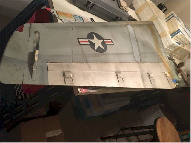
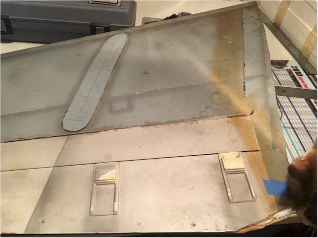
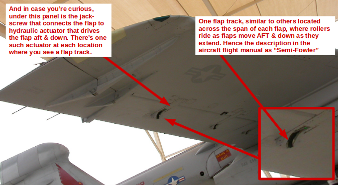
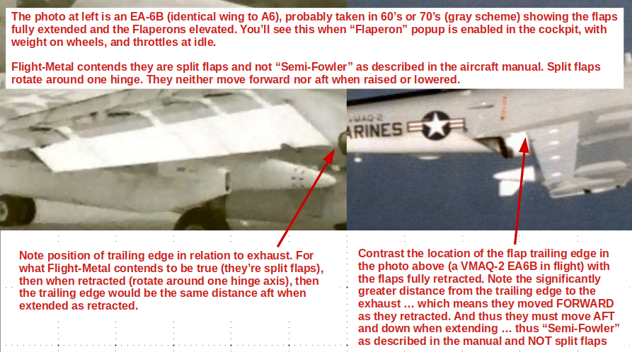
Wrong. I have no idea what you mean by trusses, as word choice seems to be imprecise. The flaps on the A6 series aircraft are "semi-Fowler" as described in the actual aircraft flight manual. Plus, as you note from the photo below, the flap tracks are clearly visible. They're present at various locations along the span of each flap section, and there are physical rollers attached to each flap at these locations. When the jack screws are energized, they drive the flaps AFT and down - with the rollers riding in those tracks. Again, not sure why you're so determined to ignore what people who've actually flown the aircraft are telling you.
* The 6 flap attachment is an extension beneath the spoileron,,,aka flaperon.
.
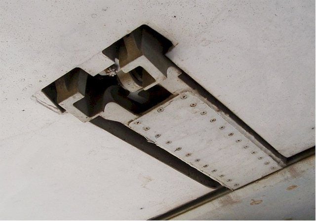
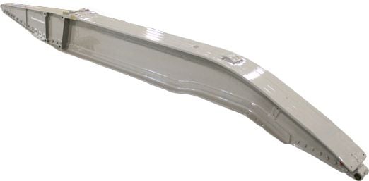
Solid sided truss box with flap track along bottom edge.

.Wrong. It's not an optical illusion. Having watched an actual A6 deploy flaps, from the cockpit in flight, from the wingman position when flying formation, from the ground while watching my Airframers do maintenance, and even once while investigating a mishap, I can assure you it is not an optical illusion. They move AFT and down, and thus are, as described in the actual flight manual, semi-Fowler flaps.
*The illusion is on my model...not the 1:1 6's.
__________________________________________________ _________________________________________
I have no idea where you ever got the impression they were used to control roll. Not on this aircraft, which is probably why the manual calls them "speed brakes." There is no differential deployment of the speed brakes on the actual aircraft. In fact, it's an emergency situation if they do (that means it's not supposed to happen). Having actually flown the actual aircraft, they extend and retract in unison on the top and bottom of the wing. They are not used for roll control. Also, please explain how the speed brakes cause a stall. They add drag - period. They're no different in that sense than extending the landing gear. If you didn't include them for simplicity purposes, that's fine, but they have no effect on stall speed (at least in the actual aircraft).
*No one said the decelerons/speed brakes on the 6's was used for roll control.
Wrong. I have no idea what you mean by trusses, as word choice seems to be imprecise. The flaps on the A6 series aircraft are "semi-Fowler" as described in the actual aircraft flight manual. Plus, as you note from the photo below, the flap tracks are clearly visible. They're present at various locations along the span of each flap section, and there are physical rollers attached to each flap at these locations. When the jack screws are energized, they drive the flaps AFT and down - with the rollers riding in those tracks. Again, not sure why you're so determined to ignore what people who've actually flown the aircraft are telling you.
* The 6 flap attachment is an extension beneath the spoileron,,,aka flaperon.
.
Solid sided truss box with flap track along bottom edge.
.
*The illusion is on my model...not the 1:1 6's.
__________________________________________________ _________________________________________
10-04-2021, 12:24 PM
#42
Look, it's clear you're intent on clinging to the spoileron language. It's inaccurate, not what's used in the aircraft manual. As for the deceleron and the extensive discussion in your earlier post, one that mentioned roll control. I'm not sure why you'd bother including that if indeed you knew that wasn't the case for the A6. And lastly, are you now saying they're semi-Fowler after all? Just because there's a complex mechanical design that produces the aft and down movement, one that involves various structures, does not mean they're not semi-Fowler - which was my point all along.
And this doesn't even address telling me the red was because they're "pinch points" something that's absolutely untrue. But hey, it's your credibility.
An optical illusion on your model? No problem. That wasn't clearly stated earlier. So my original point remains true. Namely that folks entering this into scale competitions may get dinged because the flap actuation doesn't match that on the full scale aircraft.
Last edited by franklin_m; 10-04-2021 at 12:26 PM.
10-04-2021, 12:55 PM
#43

The following users liked this post:
patf (10-05-2021)
10-04-2021, 12:57 PM
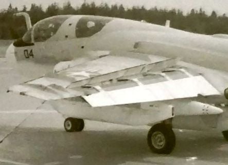
#44
I don't have a better photo of EA6B on the ground in the configuration he showed in the B&W photo, but if someone finds one, you'll see the same thing. When flaps fully extended (30 degrees vs. 20), the trailing edge of the flap next to the fuselage is really close to the exhaust. In flight, flaps fully retracted, the distance is considerably greater.
10-04-2021, 01:16 PM
#45
This is not a credibility issue nor would that matter anyway... These jets are four models of Grumman A6 Intruders...not, nor intended to be, 1:5.5 replicas.
I recognize the wording in the NATOPS and its symantics relative to structural parts of "all" USN/USMC aircraft. Anyone working within the scope of NATOPS is in their right to refer to all the functional parts as identified by NATOPS. All of my replies have been from references outside of NATOPS though I have complete copies of the Grumman A6 NATOPS...A-6A-NFM-1967-S, A-6ABCDE-NFM-Part1-S, and A-6A,B,C,D,E-NFM-Part 2-S (6A,E,EA,K Flight Manuals).
In scale competition the documentation provided by the competitor is the "only" resource utilized by the static judge...nothing more. A static judges' personal recollections/knowledge of the subject being judged are not permitted to be the point of comparison of models in competition. Subjective judging is not permitted in R/C scale contests...FAI, USSMA, AMA, nor Top Gun protocols.
These jets are four models of Grumman A6 Intruders...not, nor intended to be, 1:5.5 replicas.I recognize the wording in the NATOPS and its symantics relative to structural parts of "all" USN/USMC aircraft. Anyone working within the scope of NATOPS is in their right to refer to all the functional parts as identified by NATOPS. All of my replies have been from references outside of NATOPS though I have complete copies of the Grumman A6 NATOPS...A-6A-NFM-1967-S, A-6ABCDE-NFM-Part1-S, and A-6A,B,C,D,E-NFM-Part 2-S (6A,E,EA,K Flight Manuals).
In scale competition the documentation provided by the competitor is the "only" resource utilized by the static judge...nothing more. A static judges' personal recollections/knowledge of the subject being judged are not permitted to be the point of comparison of models in competition. Subjective judging is not permitted in R/C scale contests...FAI, USSMA, AMA, nor Top Gun protocols.


The following users liked this post:
Halcyon66 (10-04-2021)
10-04-2021, 01:59 PM
#48
There's fender bender...:^) Bama won again! The confusion appears to be contagious...pot'a'to or potato which is it in Bama? Tater?
Last edited by Flite-Metal; 10-04-2021 at 02:06 PM.
