


1/7th F-14D Scratch build thread *building started*
 06-26-2009, 07:57 PM
#26
Senior Member

Join Date: May 2006
Location: Camarillo,
CA
Posts: 234
Likes: 0
Received 0 Likes
on
0 Posts
ORIGINAL: invertmast
The wing sealing bag, i'd like to do as well, but i am having a helluva time trying to figure out how to make it happen, as i have no idea where to get the bladder bag made.. then how to inflate and suck it back down. The inflation part is simple, but getting it to suck back down flat is the difficult part, as the only way i can think of making this happen is for it to be stretched over the mounting surface slightly so the tension of the rubber bag pulls it back down.
The wing sealing bag, i'd like to do as well, but i am having a helluva time trying to figure out how to make it happen, as i have no idea where to get the bladder bag made.. then how to inflate and suck it back down. The inflation part is simple, but getting it to suck back down flat is the difficult part, as the only way i can think of making this happen is for it to be stretched over the mounting surface slightly so the tension of the rubber bag pulls it back down.
 06-26-2009, 08:31 PM
#27

ORIGINAL: Seraphim77
I've thought of experimenting with Tempur-Pedic Foam type material...something that retains its form/shape after being compressed. Even with an air bladder bag, I don't think you'd have to worry about the sucking it back down part...just let the wing push the air out and flatten it as the wing sweeps. Once the wing extends back out, the steady air source would re-inflate it. The goal is to form a seal with the wing.
ORIGINAL: invertmast
The wing sealing bag, i'd like to do as well, but i am having a helluva time trying to figure out how to make it happen, as i have no idea where to get the bladder bag made.. then how to inflate and suck it back down. The inflation part is simple, but getting it to suck back down flat is the difficult part, as the only way i can think of making this happen is for it to be stretched over the mounting surface slightly so the tension of the rubber bag pulls it back down.
The wing sealing bag, i'd like to do as well, but i am having a helluva time trying to figure out how to make it happen, as i have no idea where to get the bladder bag made.. then how to inflate and suck it back down. The inflation part is simple, but getting it to suck back down flat is the difficult part, as the only way i can think of making this happen is for it to be stretched over the mounting surface slightly so the tension of the rubber bag pulls it back down.
yea thats the thing though.. the bladder works in reverse. Its sucked down when the wings are extended and then inflates once the wings are swept back. The inflation part is simple.. its the suction part that i can't figure out.
06-26-2009, 09:12 PM
#29
Senior Member
Join Date: May 2006
Location: Camarillo,
CA
Posts: 234
Likes: 0
Received 0 Likes
on
0 Posts
ORIGINAL: Mike Emilio
What's the shape of this rubber bladder thing.
Anyone have a picture of what it looks like.
What's the shape of this rubber bladder thing.
Anyone have a picture of what it looks like.
06-26-2009, 09:13 PM
#30
ORIGINAL: Mike Emilio
What's the shape of this rubber bladder thing.
Anyone have a picture of what it looks like.
What's the shape of this rubber bladder thing.
Anyone have a picture of what it looks like.
if you look in this photo you can see a "khaki" colored part on the upper part of the fuselage that is screwed to the fuselage structure. This is the wing "sealing" bag, that is on the upper part of the fuselage aft of the over wing fairing. When the wing sweeps back, this "bag" inflates sealing the gap between the fuselage and the wing.
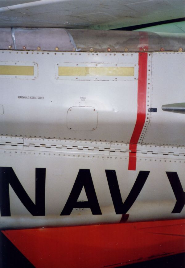
and a couple pics showing the area on the airplane:
 06-26-2009, 10:01 PM
#31
Senior Member
I have in mind something like a long belows, similar like you use to blow on a fire.
If the belows was side hinged on the inboard, of the area shape, then put into a corresponding shaped rubber bag. Almost sounds like the wing would gently push it down when swept, then spring back up when the wing clears it on extending.
I can mould a rubber bag to any shape, just need the bellows mechanism inside.
It's a long way to go to get to this stage but something to think about.
p.s sent the slat track dxf to your email.
06-26-2009, 11:22 PM
#32

My Feedback: (75)

Join Date: Jan 2002
Location: Oceanside,
CA
Posts: 1,461
Likes: 0
Received 0 Likes
on
0 Posts
Thomas, looks good bro!! I know it WILL be perfect!!! Can't wait to see the progress.
Good luck with it!
Lowell
Good luck with it!
Lowell
06-27-2009, 12:17 AM
#33
ORIGINAL: jet time
Thomas, looks good bro!! I know it WILL be perfect!!! Can't wait to see the progress.
Good luck with it!
Lowell
Thomas, looks good bro!! I know it WILL be perfect!!! Can't wait to see the progress.
Good luck with it!
Lowell
06-28-2009, 08:08 PM
#35
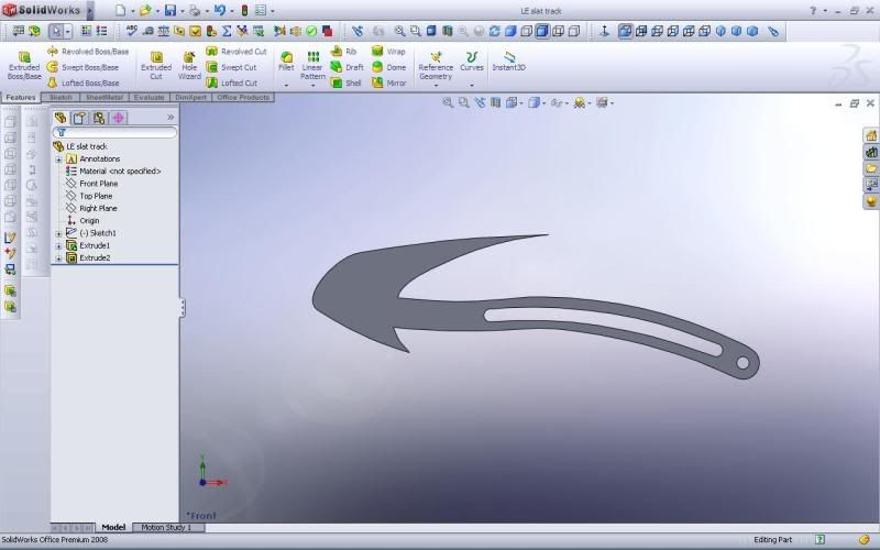
Still slowly working on some cad stuff while i'm off for work. I've got a crued drawing of the LE slat track worked out. I've got to adjust the spline points to smooth it out and thicken up the track where the "roller" slots are.. I think i'll be using 3/16" or 1/4" G-10 / Dragon plate (carbon laminated ply) for these parts and i will have them CNC cut. For rollers i'll be using either some EXTREMELY small bearings (3mm OD) which puts the slot around .125" for in the slat track. This would make a total of 6 bearings per slat track w/ 1mm spacers between the bearings and .5mm shims between the bearings and the mounting ribs in the wing. I'm almost positive that a hausl hydraulic system would be the simplest and easiest system for slat actuation, along w/ the speed brake actuation.
Some are probly wondering why hydraulic. 1. i'm 99% sure line length's have a little less influence on actuation times, so for the 3 piece speed brakes their extension and retraction could have better timing. 2. The cost for an air system to actuate everything on a model this large would be about the same as a hyrdaulic system, and with the hydraulic system theirs less chance of not getting the gear up in the wells. 3. Easier maintenance... For the slats, this would make 3 or 4 1" wide x 3 or 4" long access panels on the bottom of the wings. If i were to do a servo' actuated system, i would have to either do multiple servos (which i dont want to put servo's way out in the wing tips) or 2. do a single servo' with bellcranks and carbon pushrods (which i really dont like b/c if something were to come loose or break, your screwed. PLUS all of this would have to be installed BEFORE the wing halves are closed in the molds. This would add alot of time and $$$$$ to cost of the airframe.
Any suggestions or comments on this? I'm completely in the dark when using the hausl system, and i only have a limited knowledge of working with hydraulic systems when i was getting my A&P, and haven't messed with any since.
anyways,
here's a pic of the leading edge slat track:
And for the stabilator control, how would everyone like to see it done. Aluminum stabilator control arm is definately happening, but what about the stabilator mount in the fuselage. I know alot of companies are going w/ the aluminum mount and servo mount all in one. Is this what most people would like to see? or would a simpler system be more preferred (and a bit cheaper to make). The cheaper route would consist of the bearings in a birch ply mount (same thickness as the bearings) that are keyed into 3/16" ply bulkheads laminated with carbon... I've worked out a bit of cad stuff for the aluminum stab and servo mount.. here's a pic of that:
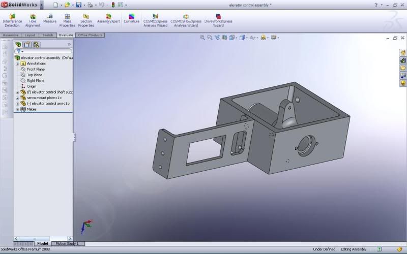
Its probly over-sized, as the assembly is 1 1/2" thick, and about 1 3/4" x 2 1/2" for the stab mount. I'll update this drawing when i get back in town w/ more accurate dimensions taken from the plans.
Some are probly wondering why hydraulic. 1. i'm 99% sure line length's have a little less influence on actuation times, so for the 3 piece speed brakes their extension and retraction could have better timing. 2. The cost for an air system to actuate everything on a model this large would be about the same as a hyrdaulic system, and with the hydraulic system theirs less chance of not getting the gear up in the wells. 3. Easier maintenance... For the slats, this would make 3 or 4 1" wide x 3 or 4" long access panels on the bottom of the wings. If i were to do a servo' actuated system, i would have to either do multiple servos (which i dont want to put servo's way out in the wing tips) or 2. do a single servo' with bellcranks and carbon pushrods (which i really dont like b/c if something were to come loose or break, your screwed. PLUS all of this would have to be installed BEFORE the wing halves are closed in the molds. This would add alot of time and $$$$$ to cost of the airframe.
Any suggestions or comments on this? I'm completely in the dark when using the hausl system, and i only have a limited knowledge of working with hydraulic systems when i was getting my A&P, and haven't messed with any since.
anyways,
here's a pic of the leading edge slat track:
And for the stabilator control, how would everyone like to see it done. Aluminum stabilator control arm is definately happening, but what about the stabilator mount in the fuselage. I know alot of companies are going w/ the aluminum mount and servo mount all in one. Is this what most people would like to see? or would a simpler system be more preferred (and a bit cheaper to make). The cheaper route would consist of the bearings in a birch ply mount (same thickness as the bearings) that are keyed into 3/16" ply bulkheads laminated with carbon... I've worked out a bit of cad stuff for the aluminum stab and servo mount.. here's a pic of that:
Its probly over-sized, as the assembly is 1 1/2" thick, and about 1 3/4" x 2 1/2" for the stab mount. I'll update this drawing when i get back in town w/ more accurate dimensions taken from the plans.
06-29-2009, 02:11 PM
#36
After talking with a few ex F-14 mechanics, its come to my attention that the wing inflation bag on the fuselage is inflated at all times when the engines are running, and the only time its not inflated is when the wings are in the "oversweep" position for storage in the hangar and carrier. Knowing this will make the decision on how to tackle the wing bag much easier.
 06-29-2009, 03:12 PM
#38
ORIGINAL: NickC5FE
Pretty sick buddy! Looking great on the slat track!
Pretty sick buddy! Looking great on the slat track!
now the question is can i Find ball bearings small enough to make use of a 2mm/2-56 bolt and still maintain a 1/8 to 3/16" slot width. If not, i may have to go with a bushing type system using aluminum and brass tubes. Ehh we will see when that time comes
06-29-2009, 03:40 PM
#39
Senior Member
Join Date: May 2006
Location: Camarillo,
CA
Posts: 234
Likes: 0
Received 0 Likes
on
0 Posts
The bag can be entirely passive in nature...ie tap 'bleed air' or intake pressure somehow when the engines are running. Or, just use that foam I was talking about and cover it with some sort of leather-type material! ;c) Check out this post and look at Dennis Crooks response on what he did with the bags:
[link]http://www.rcuniverse.com/forum/fb.asp?m=5698056[/link]
Slat rails and stab mounts done in SolidWorks look great!
[link]http://www.rcuniverse.com/forum/fb.asp?m=5698056[/link]
Slat rails and stab mounts done in SolidWorks look great!
06-29-2009, 04:03 PM
#40
ORIGINAL: Seraphim77
The bag can be entirely passive in nature...ie tap 'bleed air' or intake pressure somehow when the engines are running. Or, just use that foam I was talking about and cover it with some sort of leather-type material! ;c) Check out this post and look at Dennis Crooks response on what he did with the bags:
[link]http://www.rcuniverse.com/forum/fb.asp?m=5698056[/link]
Slat rails and stab mounts done in SolidWorks look great!
06-29-2009, 04:13 PM
#41
Senior Member
Join Date: May 2006
Location: Camarillo,
CA
Posts: 234
Likes: 0
Received 0 Likes
on
0 Posts
I agree...it would provide less complexity, weight, and hassle to deploy. It would be one less thing to service as well.
06-29-2009, 04:23 PM
#42
ORIGINAL: Seraphim77
I agree...it would provide less complexity, weight, and hassle to deploy. It would be one less thing to service as well.
I agree...it would provide less complexity, weight, and hassle to deploy. It would be one less thing to service as well.
07-02-2009, 02:02 AM
#43

Hi Thomas,
thank you to point your thread to me, I don't know how I missed it (already subscribed)!
Have a great work, I'll follow it very closely!
Best regards
Angelo
thank you to point your thread to me, I don't know how I missed it (already subscribed)!
Have a great work, I'll follow it very closely!
Best regards
Angelo
07-02-2009, 03:05 AM
#44
Join Date: Jan 2007
Location: farnborough, , UNITED KINGDOM
Posts: 3,294
Likes: 0
Received 1 Like
on
1 Post
Thomas, good luck with the project. You may already know of Servocity, but they do carry a range of interesting attachments and fittings for servos and such, including bushings and small bearings - link attached.
[link]http://www.servocity.com/html/bearings__bushings___collars.html[/link]
marcs
[link]http://www.servocity.com/html/bearings__bushings___collars.html[/link]
marcs
07-02-2009, 05:20 AM
#45

ORIGINAL: invertmast
here's a pic of the leading edge slat track:
here's a pic of the leading edge slat track:
Hi Thomas,
Great work I love your enthusiasm to start such a big project.
On this slat track, can you tell me how the bearings will work? I assume there would be 2 of them in that track? And something I have never understood is how will the bearing turn? Do you need anough slop in the track so that only one side of the bearing is touching the track?
Thanks in advance,
07-02-2009, 06:14 AM
#46
marc,
Thanks for the link.. I know about servocity, but have never used any of their stuff, i'll have to look into it.
Matt,
as far as the slat tracks, their is typically a bit of play or slop between the track and roller to allow them to move. I'll be building in this play in the rollers, but it will only be a couple of thousandths. Their will be 2 bearings for the track, which will act as a mechanical stop for fully extended and retracted as well.
07-02-2009, 11:56 AM
#47
My Feedback: (42)
Join Date: Jul 2003
Location: Charlotte,
NC
Posts: 808
Likes: 0
Received 0 Likes
on
0 Posts
Thomas,
Your link worked fine. That's one big sucker! Good luck on the build, I'll stayed tuned and read about your progress.
David
Your link worked fine. That's one big sucker! Good luck on the build, I'll stayed tuned and read about your progress.
David
07-03-2009, 06:18 PM
#48
Got a bit more stuff done today.. actually a good bit of stuff done.... I removed the vertical stab fairing "shapes" from the fuselage bulkheads, as they would be in the way of mounting the vertical stabs. Plus i plan to have these fairings integral to the vertical fins, as they will be a basis for gluing the verticals to the fuselage.. I also removed the cockpit hatch portion from some of the forward fuselage bulkheads and adjusted them to take the 1/8" floors. I modified the bulkheads to get the "curve" mentioned in some of the earlier posts, and got the jig cut out and assembled. I"m not satisfied with what you see in the photo's and it will get alot of changes to gaurantee the fuselage is 100% straight. Since i got the preliminary jig somewhat complete, i just had to install all the fuselage bulkheads and take some pictures. I also had intentions on building the horizontal and vertical stabs next week, but the local hobby shop's stock of balsa is currently Dead.. they didn't have anything that i needed, so i'll just have to keep working on what little i have left to finish and adjust before all i can do is "just build".
So here's some pictures:
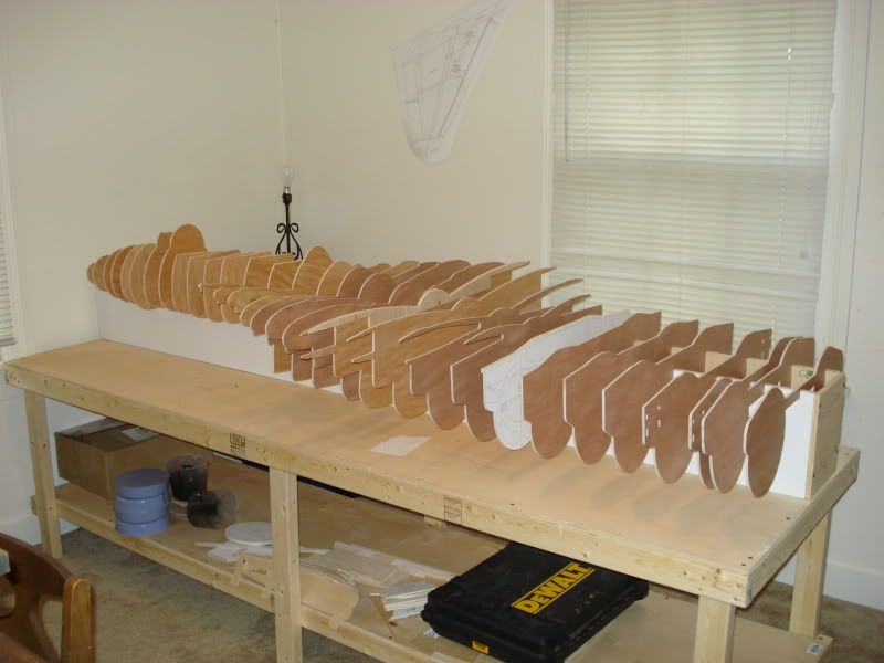
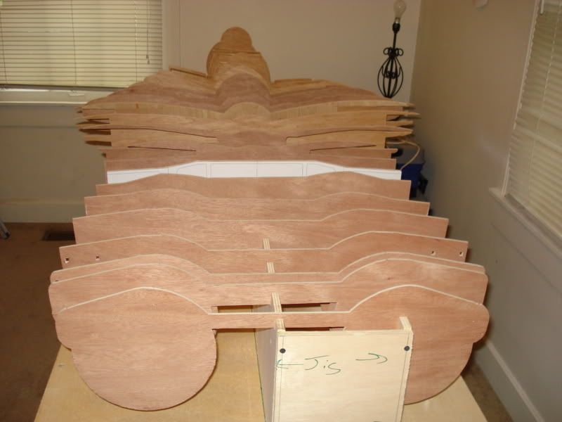
So here's some pictures:
07-03-2009, 07:13 PM
#50
ORIGINAL: Mike Emilio
Are you only going to use the right half of the jig, and not both sides?
Are you only going to use the right half of the jig, and not both sides?
I'm still debating... i was planning to use a combination of 3 different setups.
The central jig will be their, and i will have 1" steel tubing running the length of the nacelle centerlines. The jig for the nacelle centerlines will have to be trimmed down to allow for the aluminum tube.. To keep the precision, i was planning to leave the one nacelle jig full size and offset it a bit so it will still reach the span-wise centerline of the bulkheads. Plus a bit more, that i haven't figured out...
The wood jigs have to be extremely precise between the 3 of them to keep the centerlines the length of the fuselage in place, and then the centerlines side to side aligned as well. Its not going to be easy keeping the bulkheads aligned, so i'm not 100% set on what kind of jig im going to go with just yet. i'm going to play around w/ a few different ideas and see what i like the best out of them all.