


Maus - Dimensional Drawings?
 06-23-2016, 11:05 AM
#1

Thread Starter
Does anyone have any detail drawings or what not? I am looking to create a 3-D model of the iconic Maus, and trying to find any data online is nigh-impossible. (Trying to find reasonably priced 1/35 scale kits or larger is even worse).
Ideally the main items I would be looking for would be overall side skirt dimensions, track details, cross sectional profile (with dimensions), etc... I've seen snippets of dimensioned drawings like this:

So I know they exist someplace...
Hell I'd take a couple pieces of Juckenburg's 1/16 kit to measure up...
Anyone have any sources? Feel free to email or PM me...
Ideally the main items I would be looking for would be overall side skirt dimensions, track details, cross sectional profile (with dimensions), etc... I've seen snippets of dimensioned drawings like this:
So I know they exist someplace...
Hell I'd take a couple pieces of Juckenburg's 1/16 kit to measure up...
Anyone have any sources? Feel free to email or PM me...
 07-09-2016, 06:17 AM
#5
Thread Starter
So after seeing a fellow RC Club member's Converted-To-RC Juckenburg Maus, (and my kids never shutting up about the Maus in World of Tanks) and having some serious interest in RC stuff now, I lucked out and got a Juckenburg resin model. THANK YOU! BTW!
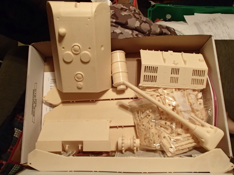
This kit is huge BTW... That fuel tank is a single solid piece!
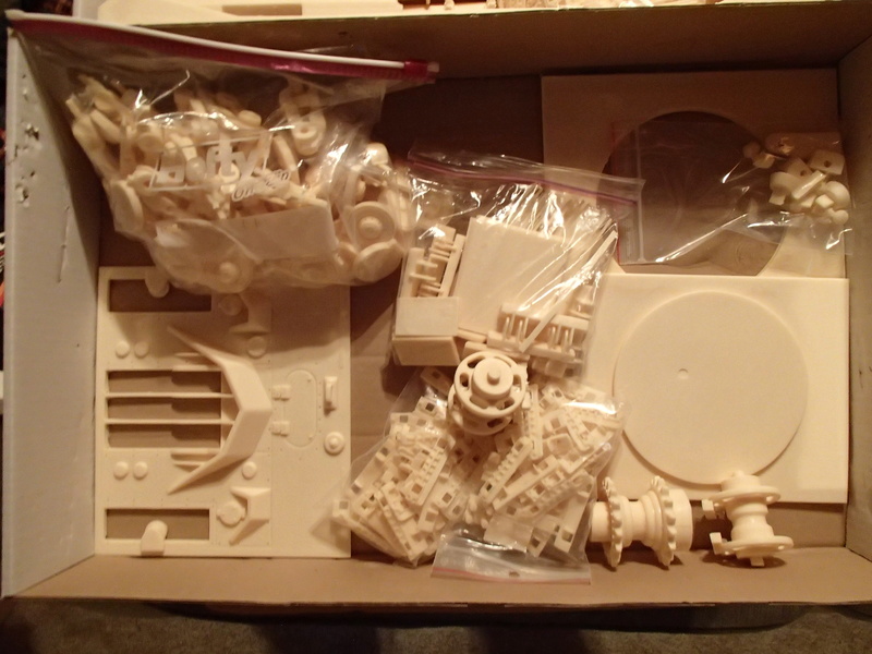
Look at all those tracks....
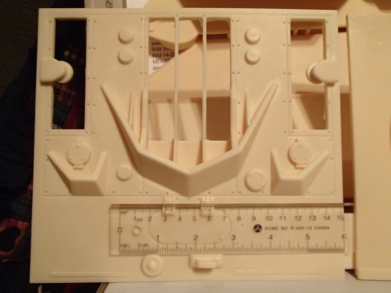
Did I mention that this is huge? still missing the side skirt armour for added width.
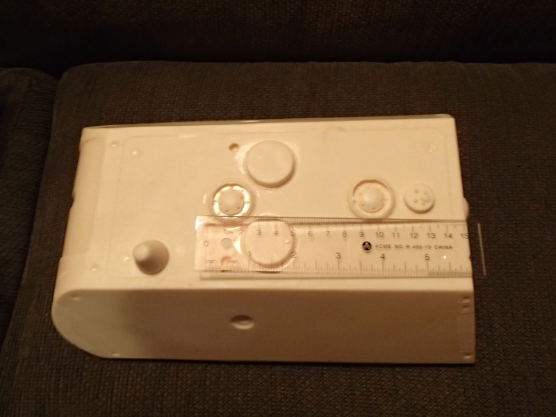
The resin turret which is fully cast (hollow with nearly 1/4" thick sides), open bottom for the turret ring portion.
So the other reason I did this was after talking to my fellow RC Club tanker and seeing his RC'd version of the above, that I'd look at designing a full aluminum version.
I had been using a copy of Panzer Tracts No. 6-3 to get some measurements to create a basic 3D model. I've also been looking into existing manufacturers regarding the drive line. So this was after a week of fiddling during lunchtimes and breaks at work... I figure that this will be a 6 month project for design alone.
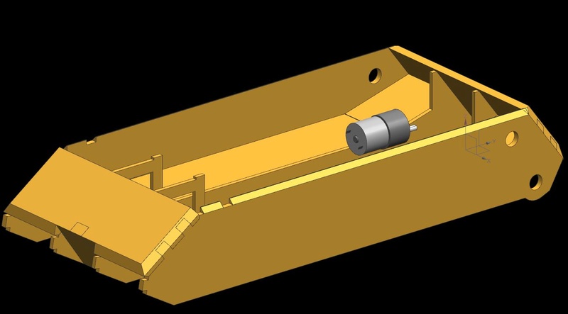
So this is currently the 9 pcs that have been rough designed.
12.7mm (1/2") front upper and lower glacis
9.525mm (3/8") rear upper glacis (lower TBD)
6.35mm (1/4") outer side skirts (TBD Turret components)
4.7625mm (3/16") inner hulls, (TBD some upper hull portions)
2.05mm (0.0808" #12 ga) inner track wells, (TBD upper hulls and turret upper plates)
TBD once the overall exterior is created, internals for structure/support. The concept is that the outer skirts will be able to be removed by taking out 4-6 bolts for access to tracks and bogeys. Upper hull plates will be magnetized for removal and the turret will be a drop in (Large enough to not need a retaining system) and a magnetically attached roof on the turret.
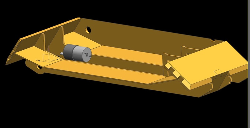
The motor/gearbox you see is a Pololu 37Dx57mm gearbox (they have dimensions online), so it was placed above the lower hull due to space limitations.
Components are interlocked to provide that "Welded" pattern.
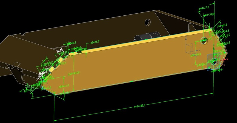
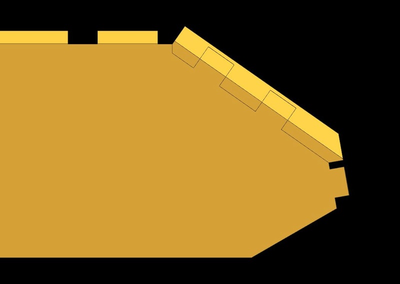
And showing some of the component dimensioning of the side skirt... Note that everything centers from the rear sprocket centerline, that just the way I design...
Anyone know of 1:10th scale King Tiger metal tracks? They would fit 1/16 Maus tracks for width... (64mm 1/10 KT vs 66mm 1/16 Maus) That going to be the toughest part IMHO...
Like I said, looking at 6 months of design, then possibly looking at a kickstarter later to get a limited production run of them made...
This kit is huge BTW... That fuel tank is a single solid piece!
Look at all those tracks....
Did I mention that this is huge? still missing the side skirt armour for added width.
The resin turret which is fully cast (hollow with nearly 1/4" thick sides), open bottom for the turret ring portion.
So the other reason I did this was after talking to my fellow RC Club tanker and seeing his RC'd version of the above, that I'd look at designing a full aluminum version.
I had been using a copy of Panzer Tracts No. 6-3 to get some measurements to create a basic 3D model. I've also been looking into existing manufacturers regarding the drive line. So this was after a week of fiddling during lunchtimes and breaks at work... I figure that this will be a 6 month project for design alone.
So this is currently the 9 pcs that have been rough designed.
12.7mm (1/2") front upper and lower glacis
9.525mm (3/8") rear upper glacis (lower TBD)
6.35mm (1/4") outer side skirts (TBD Turret components)
4.7625mm (3/16") inner hulls, (TBD some upper hull portions)
2.05mm (0.0808" #12 ga) inner track wells, (TBD upper hulls and turret upper plates)
TBD once the overall exterior is created, internals for structure/support. The concept is that the outer skirts will be able to be removed by taking out 4-6 bolts for access to tracks and bogeys. Upper hull plates will be magnetized for removal and the turret will be a drop in (Large enough to not need a retaining system) and a magnetically attached roof on the turret.
The motor/gearbox you see is a Pololu 37Dx57mm gearbox (they have dimensions online), so it was placed above the lower hull due to space limitations.
Components are interlocked to provide that "Welded" pattern.
And showing some of the component dimensioning of the side skirt... Note that everything centers from the rear sprocket centerline, that just the way I design...
Anyone know of 1:10th scale King Tiger metal tracks? They would fit 1/16 Maus tracks for width... (64mm 1/10 KT vs 66mm 1/16 Maus) That going to be the toughest part IMHO...
Like I said, looking at 6 months of design, then possibly looking at a kickstarter later to get a limited production run of them made...
07-11-2016, 04:16 AM
#7
You may want to try getting these tracks:
https://www.rapidonline.com/modelcra...lastic-51-1640
The sprockets are part 451
These I used for my Maus build and are 68mm which is very close to 16th scale and look close to the actual track too.
Here is a link to my build if you need some ideas:
http://southeastarmoreddivision.weeb...aus-build.html
07-11-2016, 04:21 AM
#8
Oh, if you want to get those tracks, call in person as the shipping calculator may still be wrong on the online order form. (should be about 30-50USD for all tracks and sprockets)
I also had to pay a 30USD customs fee via DHL when it got to the States.
I also had to pay a 30USD customs fee via DHL when it got to the States.
07-11-2016, 04:36 AM
#9
Thread Starter
I saw your Maus in my Google searches. Very nice.
I'm still in concept phase. Like I said 6 month timeline for design. By then I'll have a 3D printer and hopefully more details on the tougher stuff.
I'm still in concept phase. Like I said 6 month timeline for design. By then I'll have a 3D printer and hopefully more details on the tougher stuff.
 07-15-2016, 11:14 AM
#11
Thread Starter
A design update... Just cause 
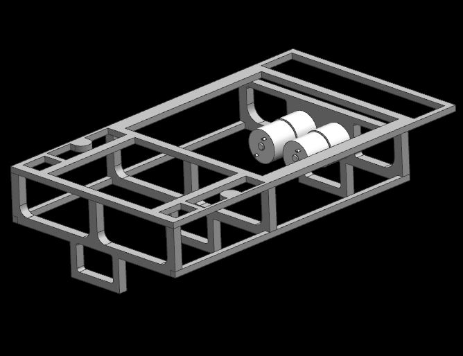
So I developed a basic framework using the external components I was modelling. 65mm inside the inner hull is scale. Ug... So small...
Main transverse framework to be 3/8" thick, all other framework to be 1/4" thick. (lasercut nesting to be completed later)
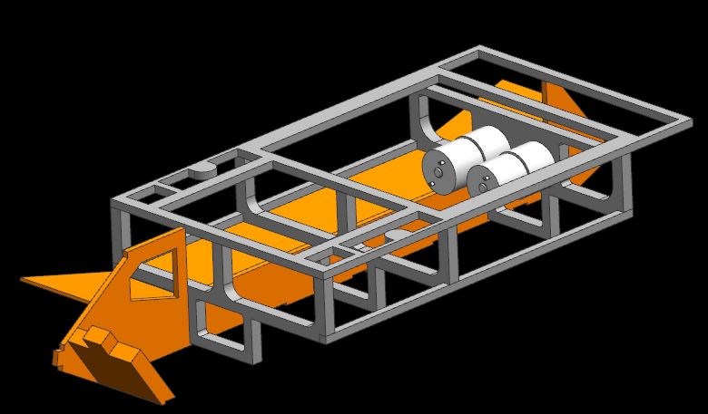
Side hulls will attach to the framework, sponson floors will attach as well. Front and rear lower Glacis plates to form part of the major framework.
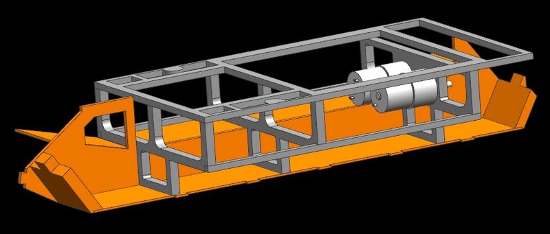
Lower hull floor attached to framework and lower glacis plates. (Left inner hull wall and sponson floor omitted for clarity)
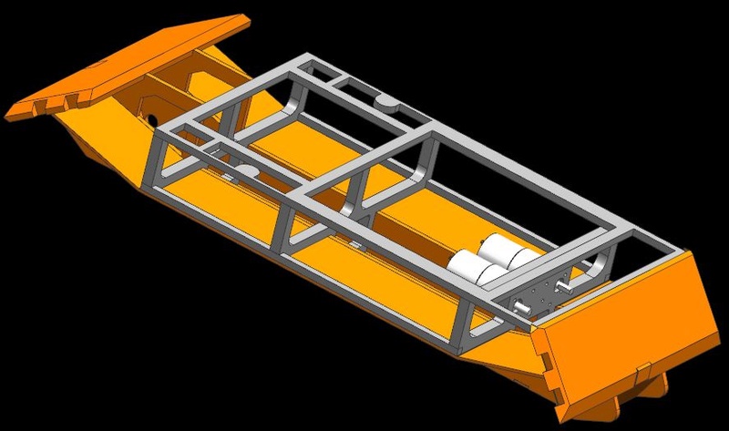
Added upper glacis plates (1/2" front, 3/8" rear) , note that there will be additional framework added for support and structural rigidity.
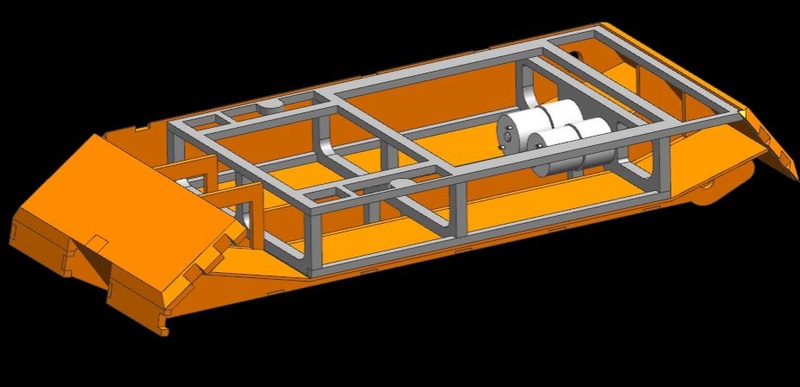
Front track armor covers put in place (1/4" thick = 2-3 3M bolts/csnk screws per for installation and solid attachment)
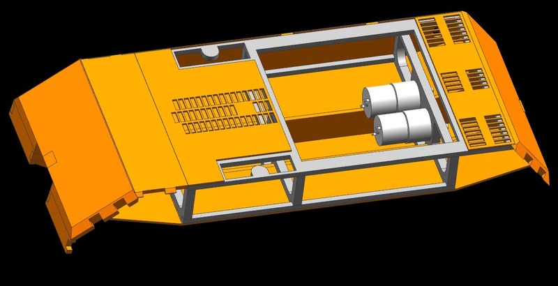
Front "crew compartment" upper panel (3/16") and primary vent panels (12ga, 0.0808") placed
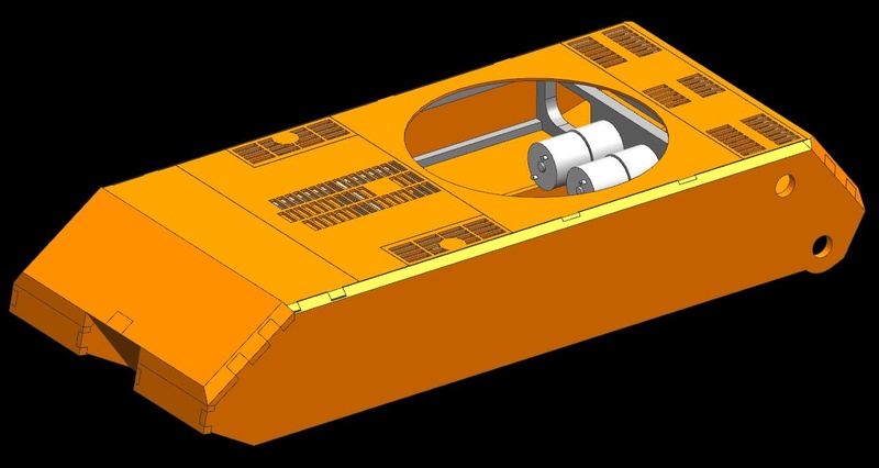
exhaust panels and turret ring in place (all 12ga /0.0808" aluminum sheet)
26pcs and mass is 5.6kg so far (not including the motors). No hardware yet, no mounting holes, but likely going to use M3 hexagon socket countersunk cap screws with flat heads. Everything is at least 2mm thick and the heads have a 1.5mm depth on a 90 degree countersink. Should be lots of holding force. The question is whether to use helicoils or not for added torque ability...
So I developed a basic framework using the external components I was modelling. 65mm inside the inner hull is scale. Ug... So small...
Main transverse framework to be 3/8" thick, all other framework to be 1/4" thick. (lasercut nesting to be completed later)
Side hulls will attach to the framework, sponson floors will attach as well. Front and rear lower Glacis plates to form part of the major framework.
Lower hull floor attached to framework and lower glacis plates. (Left inner hull wall and sponson floor omitted for clarity)
Added upper glacis plates (1/2" front, 3/8" rear) , note that there will be additional framework added for support and structural rigidity.
Front track armor covers put in place (1/4" thick = 2-3 3M bolts/csnk screws per for installation and solid attachment)
Front "crew compartment" upper panel (3/16") and primary vent panels (12ga, 0.0808") placed
exhaust panels and turret ring in place (all 12ga /0.0808" aluminum sheet)
26pcs and mass is 5.6kg so far (not including the motors). No hardware yet, no mounting holes, but likely going to use M3 hexagon socket countersunk cap screws with flat heads. Everything is at least 2mm thick and the heads have a 1.5mm depth on a 90 degree countersink. Should be lots of holding force. The question is whether to use helicoils or not for added torque ability...
07-21-2016, 01:36 PM
#12
Thread Starter
Started on some assembly and suspension....

Did some gear/driveline concepts. Hope to get with ETO for a final solution, but due to the narrow hull width (65mm internal), will use that style of gearbox to drive a 1:1 timing belt style sprocket set.
The bracket will have to be modified to allow for tensioning later on for proper belt lengths... (like I said concepts right now.) Also started to include mounting holes & hardware. Button head and countersunk for external connections (and concealed ones). and SHCS for internal connections.

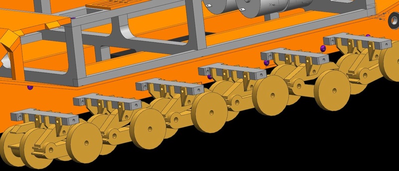
Made a suspension "Grate" for mounting the bogey assemblies. Mirror images to cut down on different parts. Sheet metal bogey mounts, all identical to mass produce (0.080" sheet, likely to be steel for strength).

Some quickly constructed models of upper and lower bogey arms with road wheels.

bogey arms are very rough but have scale contours currently. Design will use springs in each upper/lower assembly. Some clearance issues with bracketry, but the arms themselves will be attached via captive pins and "E-clips".
Soon back to real work
Did some gear/driveline concepts. Hope to get with ETO for a final solution, but due to the narrow hull width (65mm internal), will use that style of gearbox to drive a 1:1 timing belt style sprocket set.
The bracket will have to be modified to allow for tensioning later on for proper belt lengths... (like I said concepts right now.) Also started to include mounting holes & hardware. Button head and countersunk for external connections (and concealed ones). and SHCS for internal connections.
Made a suspension "Grate" for mounting the bogey assemblies. Mirror images to cut down on different parts. Sheet metal bogey mounts, all identical to mass produce (0.080" sheet, likely to be steel for strength).
Some quickly constructed models of upper and lower bogey arms with road wheels.
bogey arms are very rough but have scale contours currently. Design will use springs in each upper/lower assembly. Some clearance issues with bracketry, but the arms themselves will be attached via captive pins and "E-clips".
Soon back to real work
Last edited by Jarlath; 07-21-2016 at 01:38 PM.
08-03-2016, 11:00 AM
#15
Thread Starter
Suspension iteration. showing road wheel travel possibility.
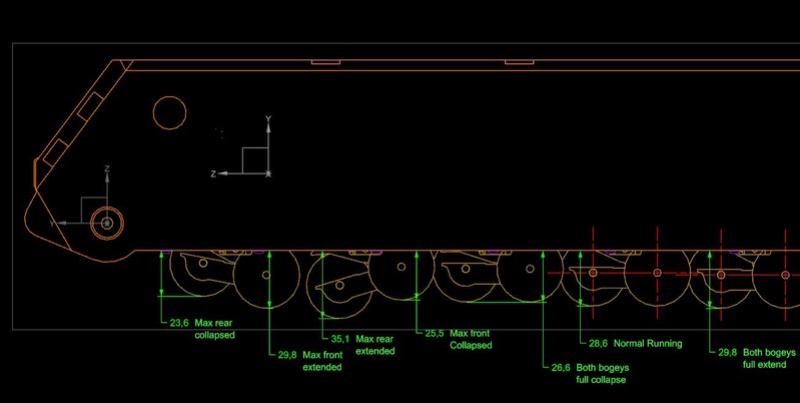
Should be only 3.2mm total travel Full unit compressed to extended, all bogeys at the same time (so far... from suspension arm limits Slightly smaller than scale 51.2mm vs 70mm theoretical design)
New component arrangement (bogey mounts and crossmembers...)
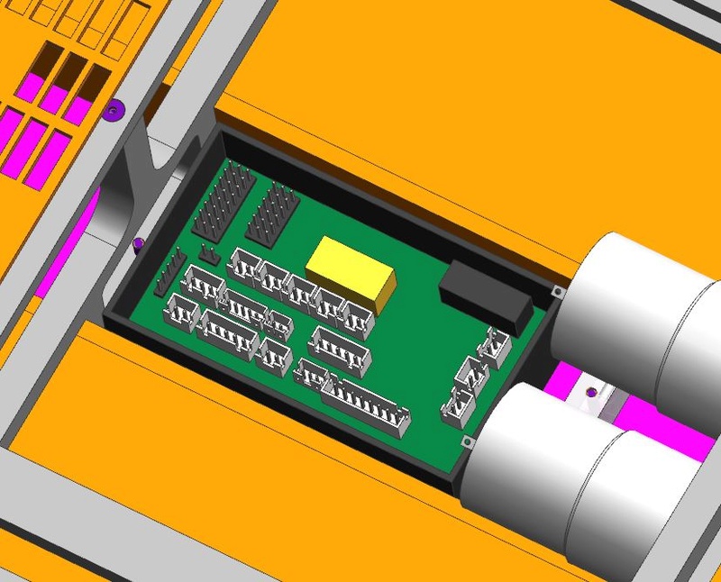
Took the time to model an IBU3 board with proper JST connectors, positions are guesstimated from images online. Overall dims are from the source
Should be only 3.2mm total travel Full unit compressed to extended, all bogeys at the same time (so far... from suspension arm limits Slightly smaller than scale 51.2mm vs 70mm theoretical design)
New component arrangement (bogey mounts and crossmembers...)
Took the time to model an IBU3 board with proper JST connectors, positions are guesstimated from images online. Overall dims are from the source
 08-10-2016, 01:52 PM
#17
Thread Starter
Some more basic work on the Maus project. Cleaned up the upper suspension arm a bit and added a cutout in the lower arm to allow for actual fitting between the two.
And then, started on the turret and tracks...

All side of the turret are to be 12.7mm thick aluminum plate (203.2mm scale, so pretty damned close)

The front of the turret will be the hardest single piece to actually create. Likely a formed/bent plate (to a specific angle) and then machined. likely rolled with the side armor angle then have the tab corners machined off.
Note the center cut out, already roughed in and should allow for the official -7, +23 elevation of the gun (guesstimated with diameter of required inner components (main barrel bore is 8mm scale, I used 14.5 as the space claimed by barrel mechanisms.

The rough intermediate track links. 2 separate P/N aligned.

Showing the "casting stiffeners" of the original. No mass relief cuts yet...

A series of them @ 10.3mm spacing (pin center to centers are approx. 165mm).

Turret roughed in place. 1mm gap currently between turret and lower hull. To be used for bearings or rotational requirements.

The side profile. Note the road wheels still in the various positions that show off the travel with regards to the track.

The blue circle is the corner of the turret travel along the hull. Looks pretty damned close to the real one. May be some tweaking once the centre armor guards get designed and put in place...
And then, started on the turret and tracks...
All side of the turret are to be 12.7mm thick aluminum plate (203.2mm scale, so pretty damned close)
The front of the turret will be the hardest single piece to actually create. Likely a formed/bent plate (to a specific angle) and then machined. likely rolled with the side armor angle then have the tab corners machined off.
Note the center cut out, already roughed in and should allow for the official -7, +23 elevation of the gun (guesstimated with diameter of required inner components (main barrel bore is 8mm scale, I used 14.5 as the space claimed by barrel mechanisms.
The rough intermediate track links. 2 separate P/N aligned.
Showing the "casting stiffeners" of the original. No mass relief cuts yet...
A series of them @ 10.3mm spacing (pin center to centers are approx. 165mm).
Turret roughed in place. 1mm gap currently between turret and lower hull. To be used for bearings or rotational requirements.
The side profile. Note the road wheels still in the various positions that show off the travel with regards to the track.
The blue circle is the corner of the turret travel along the hull. Looks pretty damned close to the real one. May be some tweaking once the centre armor guards get designed and put in place...
08-11-2016, 09:45 AM
#18
Nice work!!!
08-11-2016, 10:35 AM
#19
Thread Starter
Current mass w/o complete running gear and additional guts (as you see it in the model images, with 1/4 of the bogeys and limited track adds) is already 10kg (aluminum)... SO guessing a final mass with all electronics and guts to be double that...
So looking at a 40-45lbs beast of a tank at 1mph...
Plus whatever mass savings I do later in via weight relief cuts etc...
So looking at a 40-45lbs beast of a tank at 1mph...
Plus whatever mass savings I do later in via weight relief cuts etc...
08-11-2016, 12:17 PM
#20

Join Date: Jul 2016
Location: St louis missouri
Posts: 82
Likes: 0
Received 0 Likes
on
0 Posts
Current mass w/o complete running gear and additional guts (as you see it in the model images, with 1/4 of the bogeys and limited track adds) is already 10kg (aluminum)... SO guessing a final mass with all electronics and guts to be double that...
So looking at a 40-45lbs beast of a tank at 1mph...
Plus whatever mass savings I do later in via weight relief cuts etc...
So looking at a 40-45lbs beast of a tank at 1mph...
Plus whatever mass savings I do later in via weight relief cuts etc...
08-12-2016, 05:55 AM
#21
Thread Starter
I'll have to put up an image showing material thicknesses.
09-15-2016, 09:47 AM
#22
Thread Starter
So I decided to buy some scale maus tracks for reference. Many thanks to Mark @ Mark 1 tanks for the opportunity to snag the last of the remaining tracks from his epic 1/6th scale maus.
As for an update... Been working heavy on the tracks... 8 degrees one way per link, 225 degrees the other.
The main cleat is 66 mm wide and those pin holes are 2mm in diameter.
Some creative liberty with "exact" precision of the casting webbing in the original mold. Going to be submitting these components to an aluminum casting company locally to see how much they will roughly cost...
I'm hoping that they come out decent... 56 pairs of links per side... 112 main cleats, 224 outer links, and 112 center links per side.... Out of aluminum, each track set should be roughly 0.8kg (1.75 lbs) not including 112 track pins (56mm long) per side. Or I use dual pins per pivot akin to mato Jagdpanther tracks...
Tried my hand at nesting for sheets of metal for cutting...
This is a 4' x 8' sheet of 1/2" aluminium laid out for 50 units for abrasive waterjet cutting.
The ONLY items on this sheet are, Front upper and lower glacis, and 4 turret sides (front, sides and rear). 6 pcs... That is it...
06-13-2017, 06:52 AM
#23
Thread Starter
It has been awhile, but I'll thread resurrect because there has been some progress...
My efforts are limited by Space, time and $$$; in that order...
However, I got the 3D printer up and running.. So time for prototyping...

So those are my track links designed roughed out via 3D printer to determine viability... 66mm wide...
So new plan while I wait for space, time, and garage electricals, milling machine, and more $$$... Is to 3D print the whole Maus for proof of concept. Also means that smaller details such as the armoured deflector skirts on the upper hull will be 3D printed...
My efforts are limited by Space, time and $$$; in that order...
However, I got the 3D printer up and running.. So time for prototyping...
So those are my track links designed roughed out via 3D printer to determine viability... 66mm wide...
So new plan while I wait for space, time, and garage electricals, milling machine, and more $$$... Is to 3D print the whole Maus for proof of concept. Also means that smaller details such as the armoured deflector skirts on the upper hull will be 3D printed...
06-13-2017, 08:33 AM
#24
Wonderful engineering,
I sure could have benefited from your analysis when building mine, in particular the issue you noticed:
" The blue circle is the corner of the turret travel along the hull. Looks pretty damned close to the real one. May be some tweaking once the centre armor guards get designed and put in place.. "
Actually had this issue as the turret ring guard does ride very close to the hull and the engine cooler guard clearance was a challenge clearing turret rotation!

