


3D Print Project SSYMS 80 ton 1/16th Scale
 05-28-2020, 11:08 AM
#51

Thread Starter

I agree, practically every part for the CR-10 series of printers is available on line.
From power supplies to control boards, I have found every part I have ever looked for and they are usually very inexpensive.
As far as new printers I have been looking at the new CR-10 V2 and V3 printers as my next printer, they have improved the CR-10, added some new features and the price is lower than what I paid for my CR-10S two years ago. The big difference between the V2 and V3 is the V3 has a Titan direct drive and I believe a V6 hot end.
Steve
 06-03-2020, 01:51 PM
#52
Wondering what the major advantage of the CR10V2 is vs the CR10S? Most of the features are already available as upgrades for the CR10S and the blurb on the Creality page compares the V2 to the original CR10, not the 10S?
06-04-2020, 12:08 AM
#53
Thread Starter
Martin,
You are absolutely right most features on the CR-10 V2 version can be added to my original CR-10S I have done some of them.
The CR-10 V2 has the dual Z axis stepper motors like the original CR-10S and is available with both the BL touch and the Titan Direct Drive.
The V2 also has the quieter stepper drivers and the frame reinforcement.
My original CR-10S already had the dual Z axis I believe the BL touch and Direct drive can both be added to it as well.
I wanted a second printer that I was familiar with and I was hesitant to upgrade my existing printer beyond a certain point, without a backup in place, in case I had any issues doing the upgrades I wanted.
Additionally I wanted to increase my ability to print more parts faster.
I find I spend half of my print time printing things for other people, so I will soon be able to do my projects full time and still print stuff for other people.
Steve
The following users liked this post:
Panther F (06-04-2020)
10-01-2020, 12:12 AM
#54
Thread Starter
It has been a while since I have posted any update, The pandemic has made me very busy, you see I sell and build video streaming systems, as you can imagine everyone needs to stream nowadays, schools, churches, corporate entities are all having to start streaming to provide service for their students, congregations and their employees and customers in order to do business.
Consequently I have not had as much free time as I need or would like to complete some of my ongoing projects.
My belt sander finally came in, as did my new printer, I haven�t even taken the time to assemble and setup either one yet.
With what little free time I have had I spent designing and printing the loading ramp that was used to drive the tanks onto the SSYMS rail car.
Here are some pictures of the parts I have designed so far using photos of the 1/35th scale ramp made by trumpeter for their SSYMS rail car. It would have been nice to have plans for this item to ease the designing process, but I manged to muddle through.


Above are the exploded views of some of the parts. The only things missing in the pictures are the cross bars which support the diamond plates and the hinge that joins the short ramp and long ramp together. I cheated a little on the cross bars, as compared to the Trumpeter kit parts, as I did not want to have 15 cross pieces to print so I only have nine and some are duplicated by making mine rectangular, they pull double duty as each bar has a different height and width so I only have to rotate them to use them in another position.
I think I got pretty close on the dimensions, I shortened the long ramp a little to fit the print bed, of course after I printed the ramps I realized I could just rotate it diagonally to fit the bed in the correct length so I am redoing those parts luckily it won�t affect much else except the diamond plate that spans the space between the ramps. I will just need to reprint some more plates. The ramps I printed will still work just at a slightly steeper angle.
I will post some pictures of the printed parts, as soon as I take them.
Steve
Consequently I have not had as much free time as I need or would like to complete some of my ongoing projects.
My belt sander finally came in, as did my new printer, I haven�t even taken the time to assemble and setup either one yet.
With what little free time I have had I spent designing and printing the loading ramp that was used to drive the tanks onto the SSYMS rail car.
Here are some pictures of the parts I have designed so far using photos of the 1/35th scale ramp made by trumpeter for their SSYMS rail car. It would have been nice to have plans for this item to ease the designing process, but I manged to muddle through.
Above are the exploded views of some of the parts. The only things missing in the pictures are the cross bars which support the diamond plates and the hinge that joins the short ramp and long ramp together. I cheated a little on the cross bars, as compared to the Trumpeter kit parts, as I did not want to have 15 cross pieces to print so I only have nine and some are duplicated by making mine rectangular, they pull double duty as each bar has a different height and width so I only have to rotate them to use them in another position.
I think I got pretty close on the dimensions, I shortened the long ramp a little to fit the print bed, of course after I printed the ramps I realized I could just rotate it diagonally to fit the bed in the correct length so I am redoing those parts luckily it won�t affect much else except the diamond plate that spans the space between the ramps. I will just need to reprint some more plates. The ramps I printed will still work just at a slightly steeper angle.
I will post some pictures of the printed parts, as soon as I take them.
Steve
10-01-2020, 12:35 AM
#55
Great to see the project was not lost or shelved. Everyone would understand under these circumstances of todays 'new normal'.
Still excited and interested in this one.
Still excited and interested in this one.
10-01-2020, 03:06 PM
#56
Thread Starter
Panther F,
Thanks for the feedback.
I have too much time invested to let this project fall by the wayside and I promised myself I would get this done before I would move on to complete my next major project, the16 ton Fries Strabokran and the V2 rocket in 1/16th scale.
Steve
Thanks for the feedback.
I have too much time invested to let this project fall by the wayside and I promised myself I would get this done before I would move on to complete my next major project, the16 ton Fries Strabokran and the V2 rocket in 1/16th scale.
Steve
10-20-2020, 06:31 PM
#57
Thread Starter
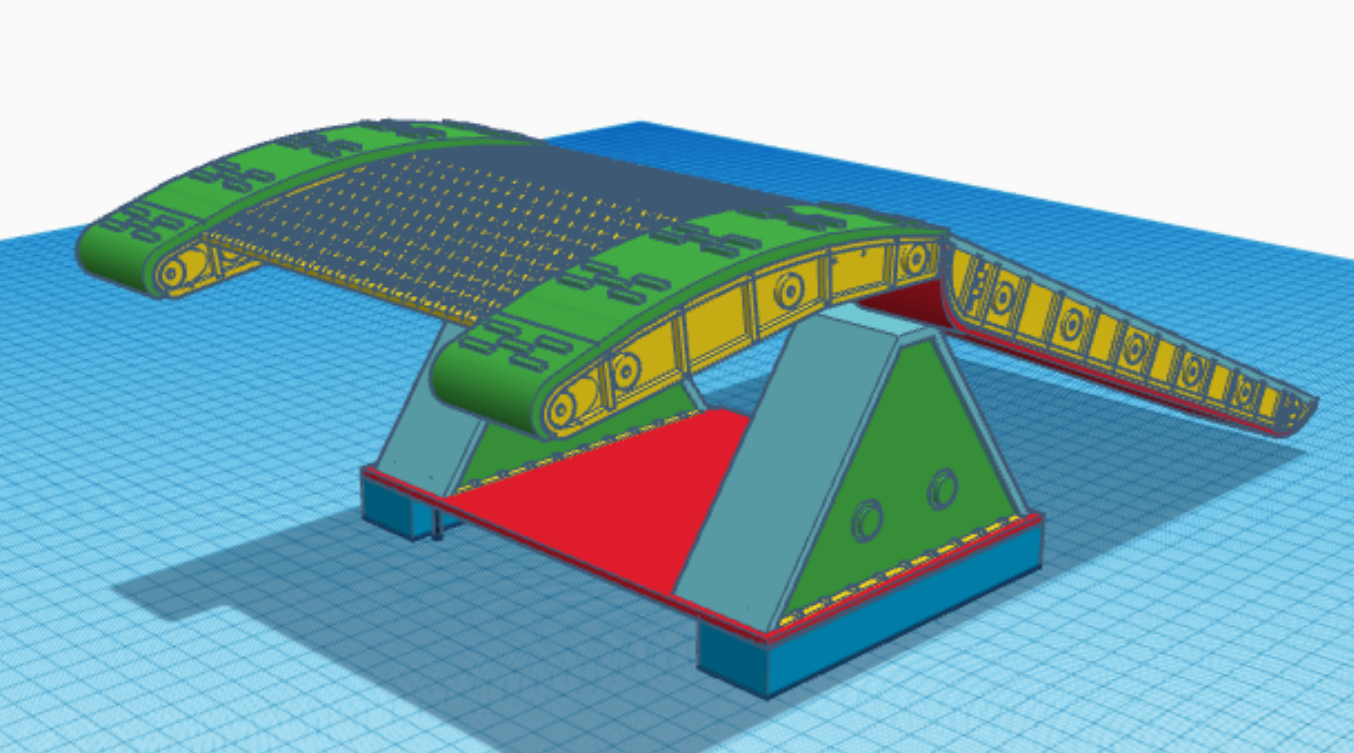
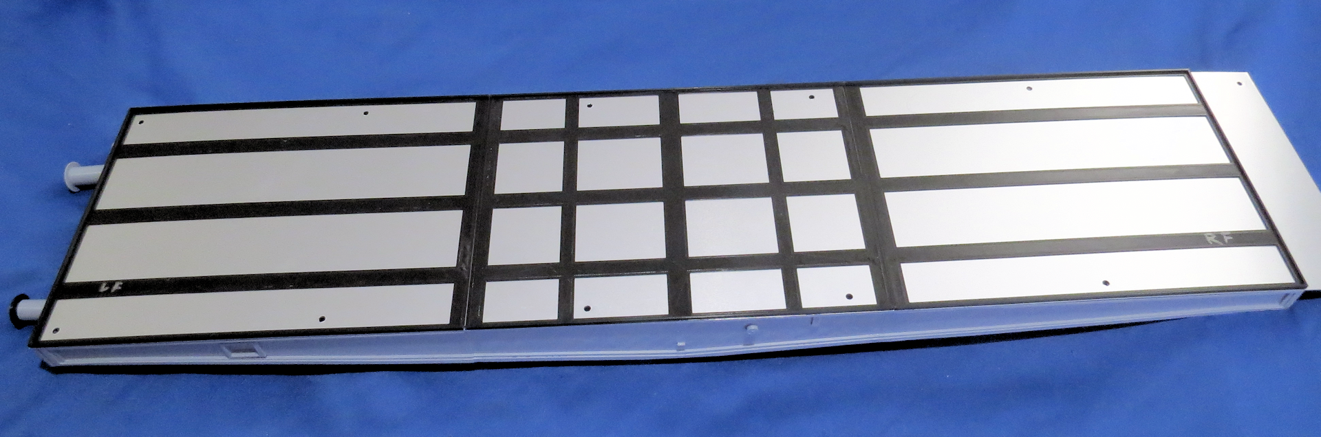
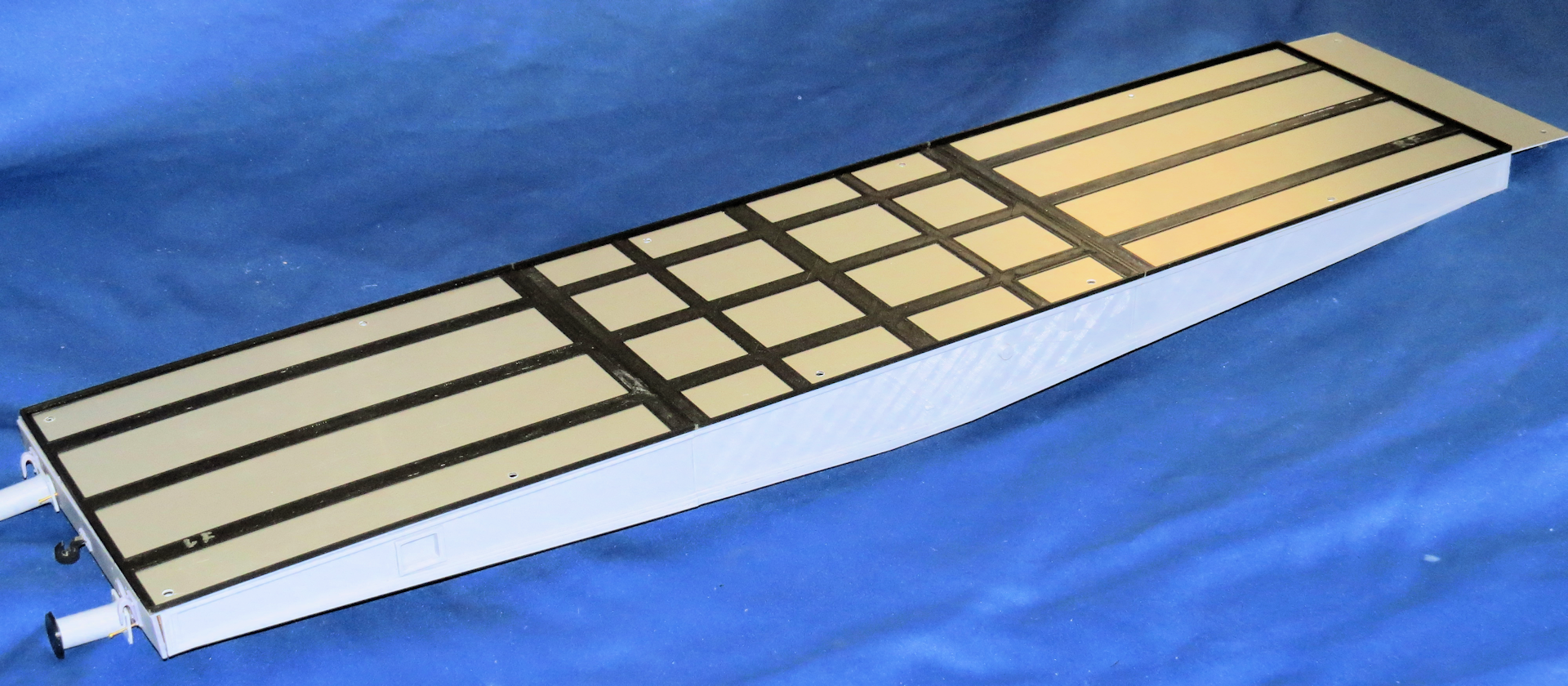
I finally got around to taking some pics of the revised 3D printed ramp parts I designed, the ramp is mostly assembled by this time.
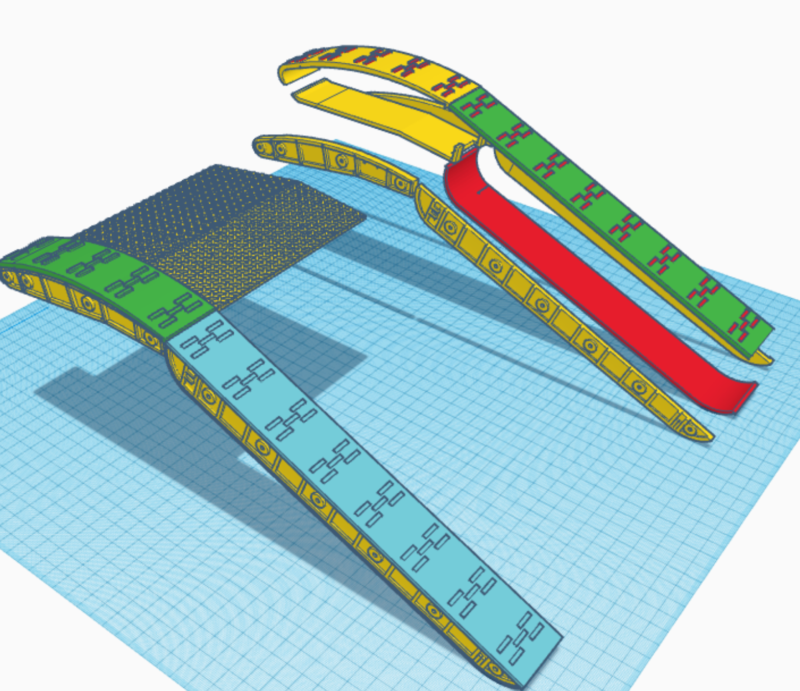
I redesigned and reprinted the long ramp parts so they would be closer to the correct length, they are now 346mm in length, increasing the ramp total length when fully extended to around 500 mm or just under 20 inches.
The first picture is the TinkerCad screen showing the parts required, most are duplicated (so not all are shown) for a total of 52 parts including the diamond plates (also not shown in this picture).
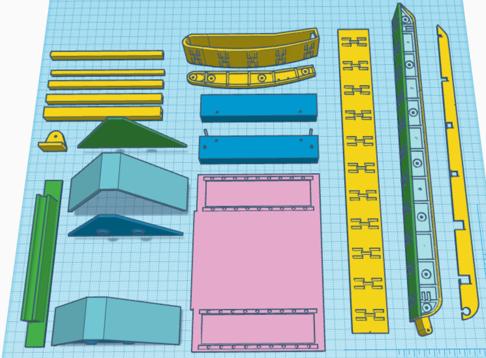
Of the diamond plates required there are six for the long ramp and only two for the short. I made the cross bars underneath hollow so I could insert a steel rod to give it more strength in case the tank track happens to run on top of the diamond plates (I am sure at some point this will happen).
The other items not previously pictured are the cross bars and the end pieces that attach to the front of the short ramp that are placed on top of the rail cars bed.
Additionally for assembly there are several hardware components required the "L" brackets at the front are attached with 2mm button head screws and nylon insert lock nuts as there is no accessing them after the ramp parts are glued together I had to be sure they would not come loose over time, thread lock would have worked equally well but I had the lock nuts on hand. Then there are the 10 steel rods that are inserted into the hollow crossbars.
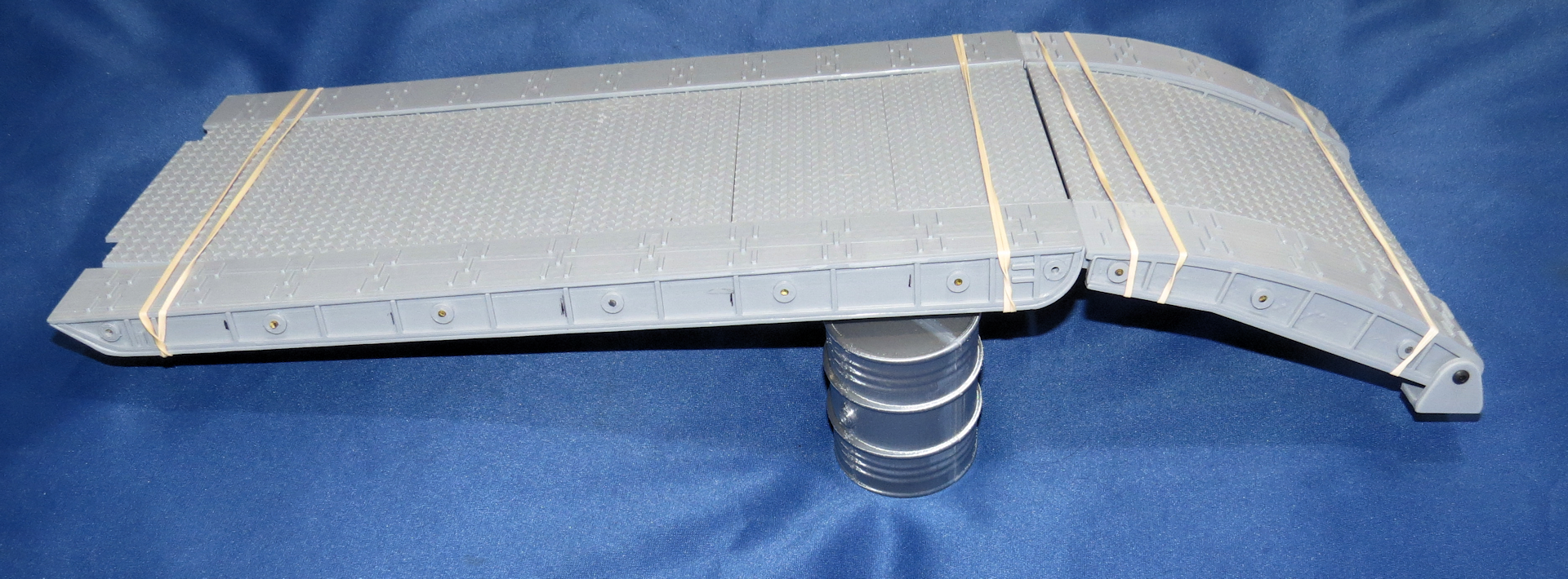
Long & Short Ramps
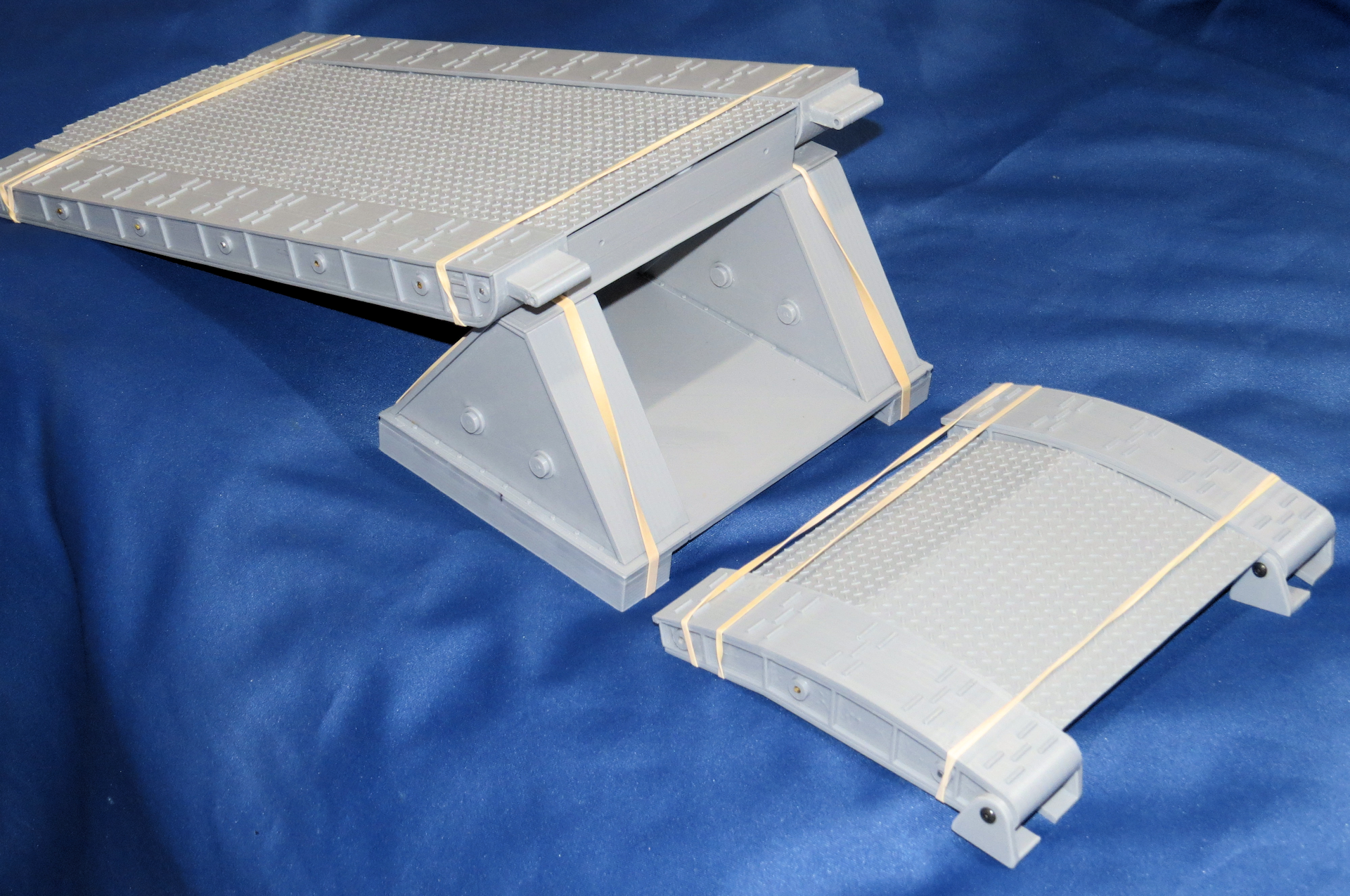
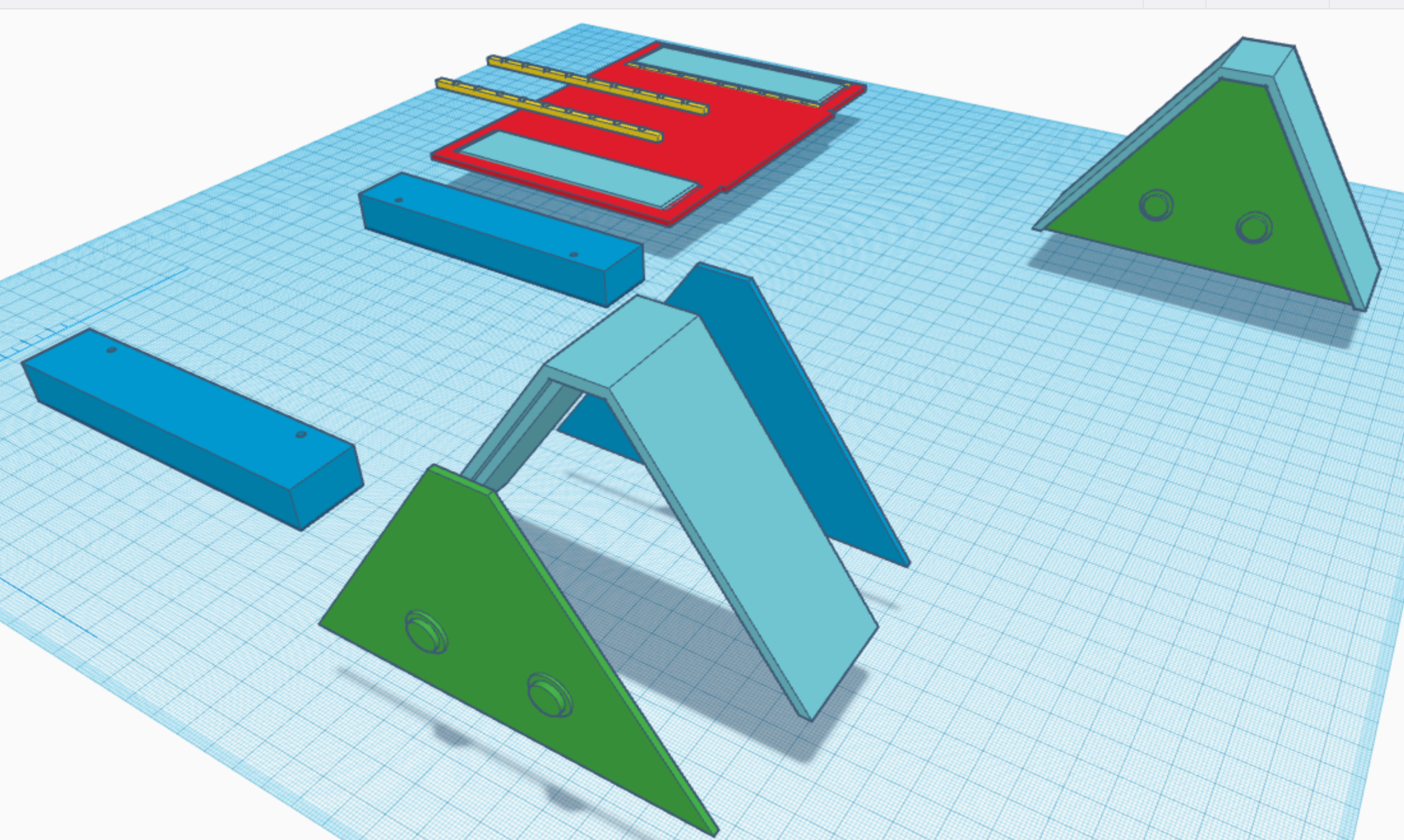
Long & Short Ramp Disassembled

Front of Short Ramp
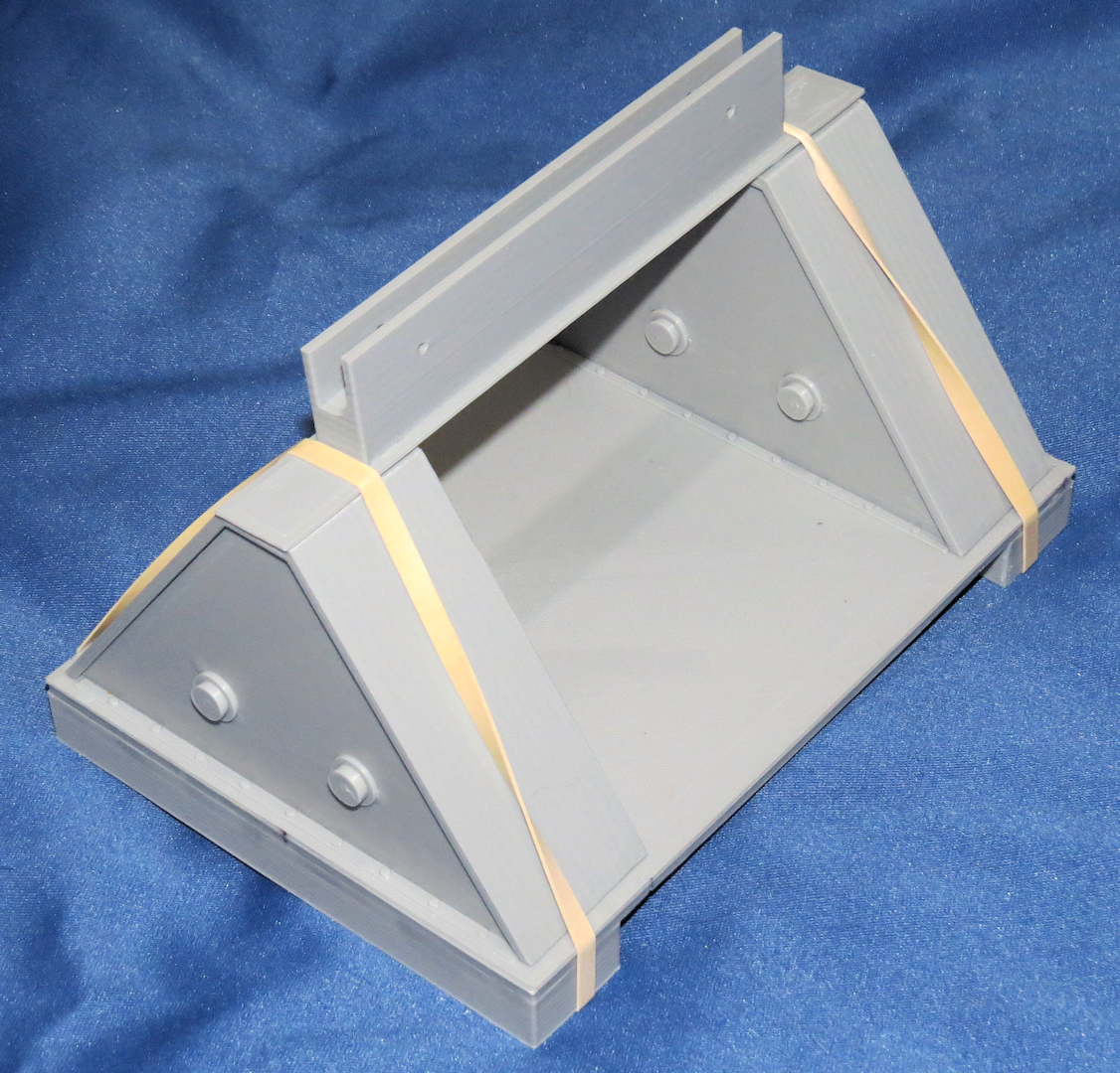
Ramp Support
Ultimately everything will be glued together except for the joint between the short ramp and the long ramp, as I made this able to pivot for different heights if necessary and the ramp to the triangular base will not be glued for ease of disassembly for transport.
That's all for now.
I redesigned and reprinted the long ramp parts so they would be closer to the correct length, they are now 346mm in length, increasing the ramp total length when fully extended to around 500 mm or just under 20 inches.
The first picture is the TinkerCad screen showing the parts required, most are duplicated (so not all are shown) for a total of 52 parts including the diamond plates (also not shown in this picture).
Of the diamond plates required there are six for the long ramp and only two for the short. I made the cross bars underneath hollow so I could insert a steel rod to give it more strength in case the tank track happens to run on top of the diamond plates (I am sure at some point this will happen).
The other items not previously pictured are the cross bars and the end pieces that attach to the front of the short ramp that are placed on top of the rail cars bed.
Additionally for assembly there are several hardware components required the "L" brackets at the front are attached with 2mm button head screws and nylon insert lock nuts as there is no accessing them after the ramp parts are glued together I had to be sure they would not come loose over time, thread lock would have worked equally well but I had the lock nuts on hand. Then there are the 10 steel rods that are inserted into the hollow crossbars.
Long & Short Ramps
Long & Short Ramp Disassembled
Front of Short Ramp
Ramp Support
Ultimately everything will be glued together except for the joint between the short ramp and the long ramp, as I made this able to pivot for different heights if necessary and the ramp to the triangular base will not be glued for ease of disassembly for transport.
That's all for now.
The following users liked this post:
Panther F (10-21-2020)
08-25-2021, 12:49 AM
#58
Thread Starter
SSYMS UPDATE
It has been a while since I posted any updates regarding my SSYMS 80 ton German Flatbed rail car for Tiger 1 and King Tiger.
I have done quite a lot since my last post.
I recently acquired a Resin 3D printer and of course I had to reprint some detail parts with it. The main bed endplates and some of the bogie detail parts, the resin printer allows me to combine several assemblies together and print them as a single unit something not possible due to the limitations of printing on my FDM printer.
After working on several other projects I have finally come to actually start the assembly process of the SSYMS.
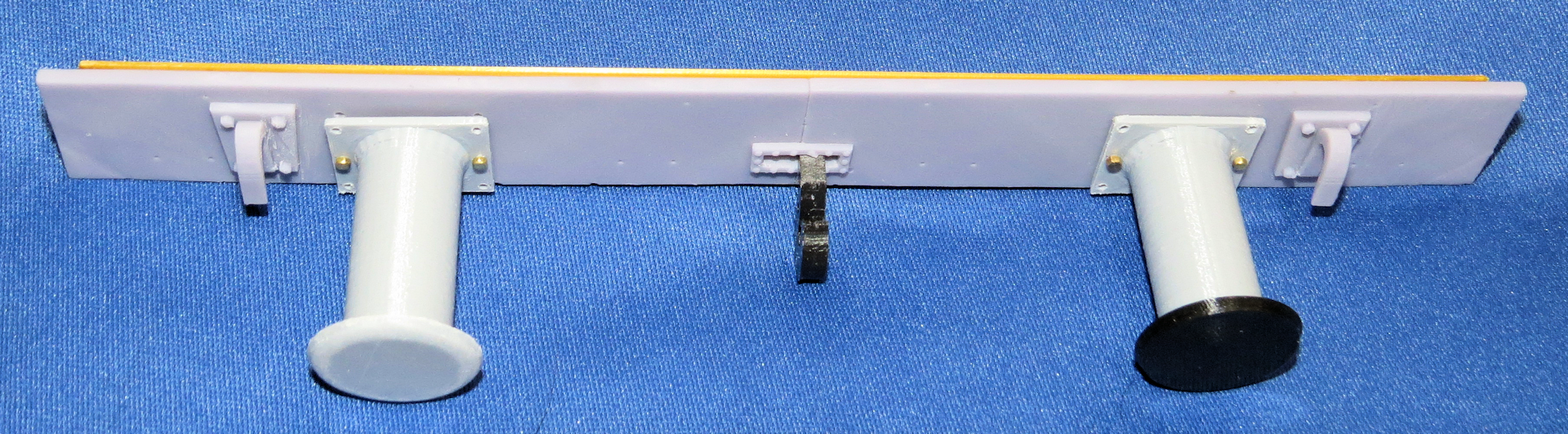
I started off with the Rail End Stop. One of my first resin prints, I printed it as one solid component with only the RR ties and the actual buffers as separate pieces which were attached to it using 00-90 screws.
The buffers are PLA and spring loaded so they will actually function, the ties are resin to get the wood grain detail.
We�ll see how well the resin and PLA plastic hold up under the abuse they will likely get. I previously printed all the parts in PLA separately, so I will assemble those units as well the single resin piece was more of a test to see if I could print it as a single piece, which worked except one of the thinner cross braces did break as I was removing the support structures, it was easily repaired.


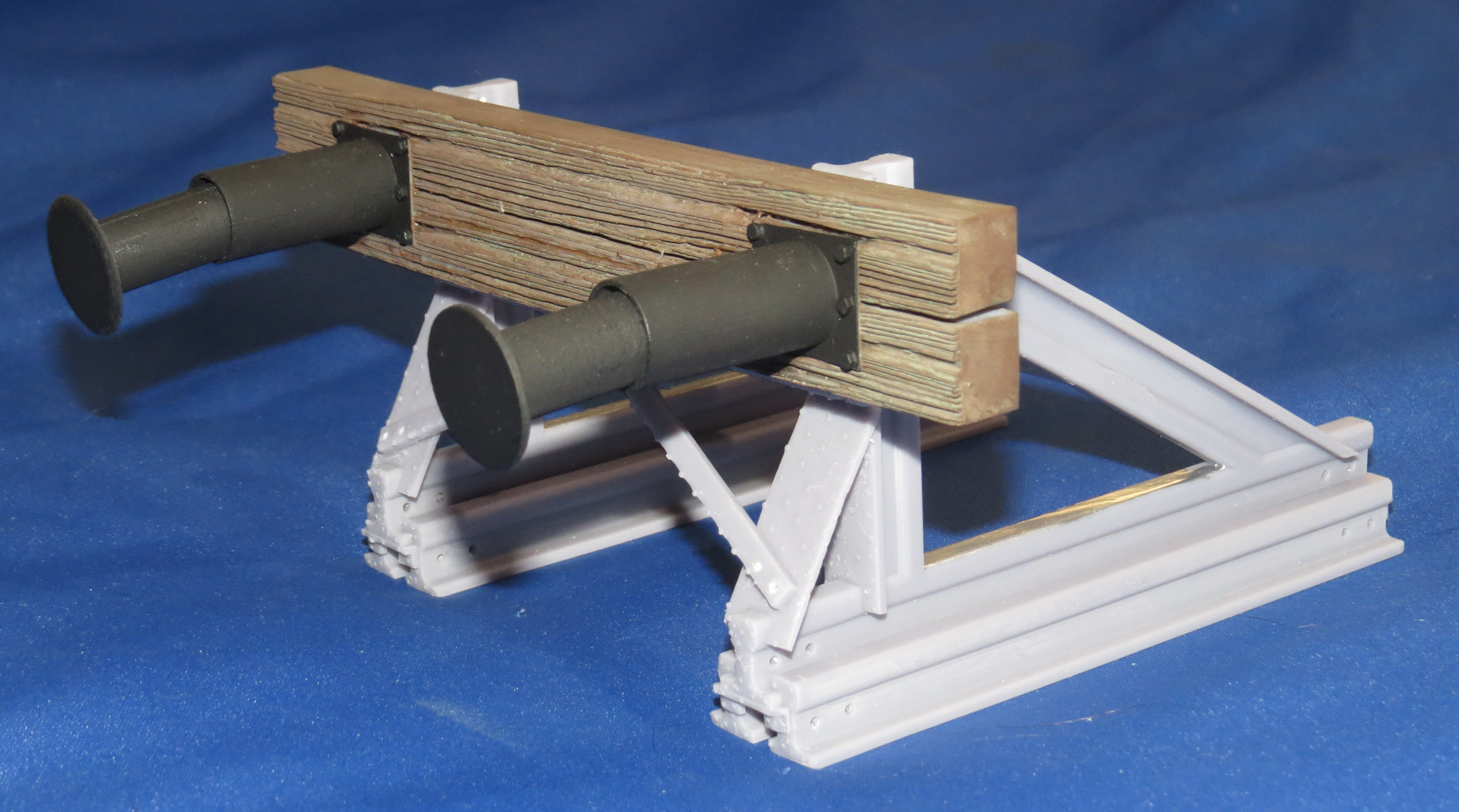

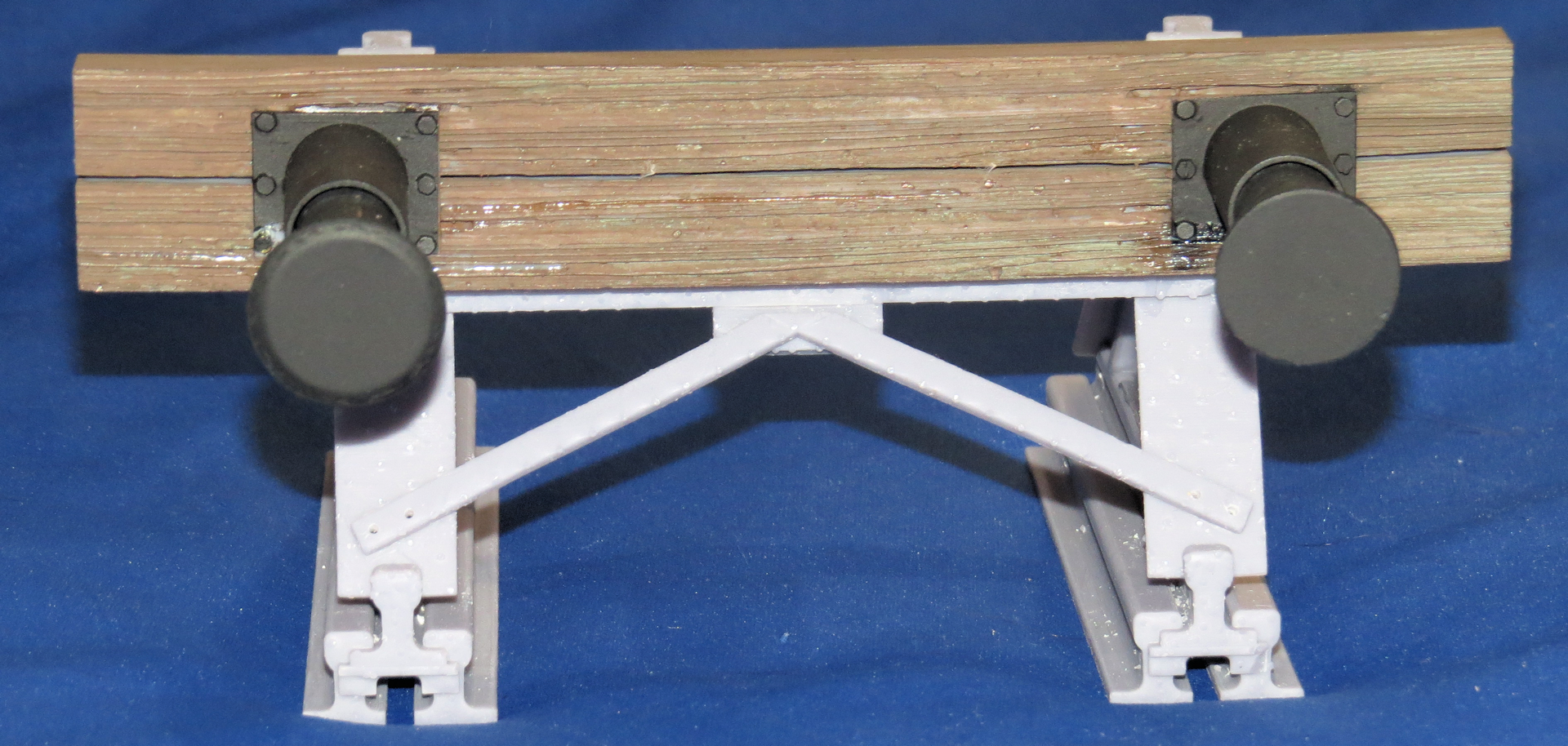
I haven't clean up all the nubs leftover where the supports attached to the model. I rushed to put it together to show at the tank club event in Largo.
I shot a bunch of pictures tonight so there is more to come.
Steve
It has been a while since I posted any updates regarding my SSYMS 80 ton German Flatbed rail car for Tiger 1 and King Tiger.
I have done quite a lot since my last post.
I recently acquired a Resin 3D printer and of course I had to reprint some detail parts with it. The main bed endplates and some of the bogie detail parts, the resin printer allows me to combine several assemblies together and print them as a single unit something not possible due to the limitations of printing on my FDM printer.
After working on several other projects I have finally come to actually start the assembly process of the SSYMS.
I started off with the Rail End Stop. One of my first resin prints, I printed it as one solid component with only the RR ties and the actual buffers as separate pieces which were attached to it using 00-90 screws.
The buffers are PLA and spring loaded so they will actually function, the ties are resin to get the wood grain detail.
We�ll see how well the resin and PLA plastic hold up under the abuse they will likely get. I previously printed all the parts in PLA separately, so I will assemble those units as well the single resin piece was more of a test to see if I could print it as a single piece, which worked except one of the thinner cross braces did break as I was removing the support structures, it was easily repaired.
I haven't clean up all the nubs leftover where the supports attached to the model. I rushed to put it together to show at the tank club event in Largo.
I shot a bunch of pictures tonight so there is more to come.
Steve
The following 3 users liked this post by Shark27:
08-25-2021, 04:44 AM
#59
Looking great, hope to see more. Hope the V2 is still on!
08-25-2021, 03:42 PM
#61
Thread Starter
RC BobM,
I can't take credit for the wood grain effect I downloaded it on Thingiverse and cut and sized it to my needs.
I have printed some of the railway ties with that wood grain but most of mine will be actual hardwood with only the plastic ties at key places, it takes a long time to print those in 1/16th scale and considering how many are required there are 40 ties per 65 feet which in 1/16th scale is almost exactly 4 feet which is how long the board the SSYMS will be displayed on, so I will need to make 40 ties.
On the hard wood ties that I use, I will probably cover them with more ballast to hide the fact they do not have the same texture as the printed ties. I am almost certain I do not want to add texture to 32 ties that are mostly hidden under the SSYMS wagon.
When I designed the printed ties I am using, I hedged my bets I made some with the track chairs built in and some without, on those I did provide a depression for the chairs to sit, in order to keep the proper rail spacing, after all I don't want a derailment.
Back to the build.
My next assembly step was to attach the main “I” Beam grid structure together, again there is piano wire inside the beams towards the ends where they are joined, for alignment and strength.
I then bonded the assembled sides to the center grid structure. Lastly I bonded the end plates to the sides and the grid structure.
Additionally I added JB Weld to reinforce the structures at specific joint locations. The epoxy was a little runny so controlling where it went was a little difficult, I had to clean off the excess by filing it away after it had completely hardened.
I also tried some plastic epoxy putty at several locations this was much easier to apply exactly where I wanted it, once painted it will all be invisible to the eye.
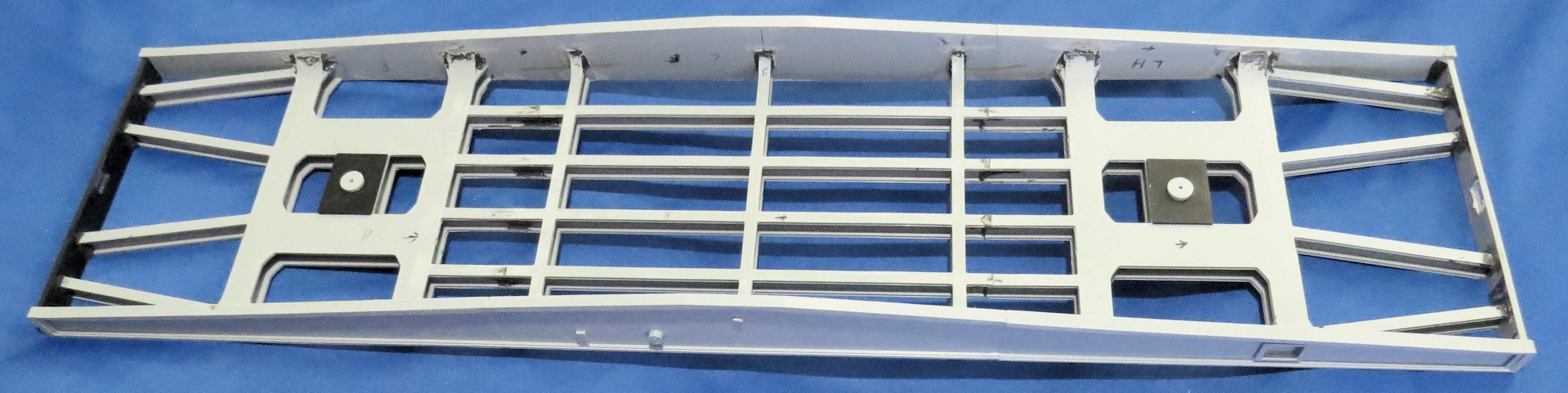
Underside of bed with slip sheets around posts and JB Weld at joints.
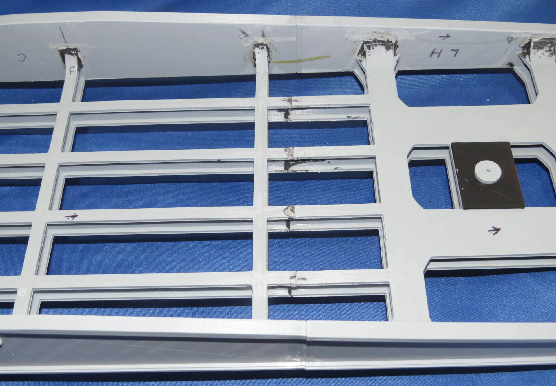
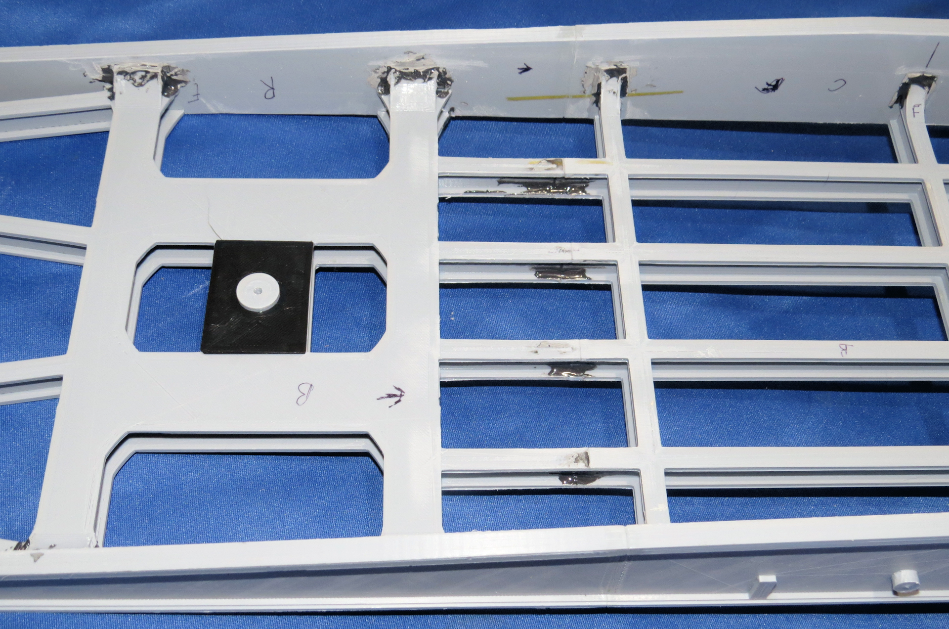
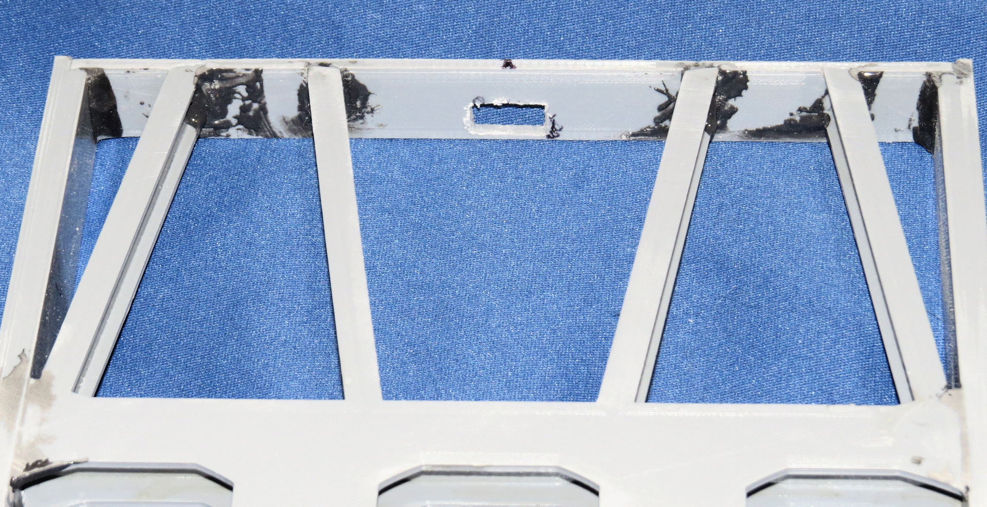
It is not pretty but once painted black it will be invisible, since it is underneath.
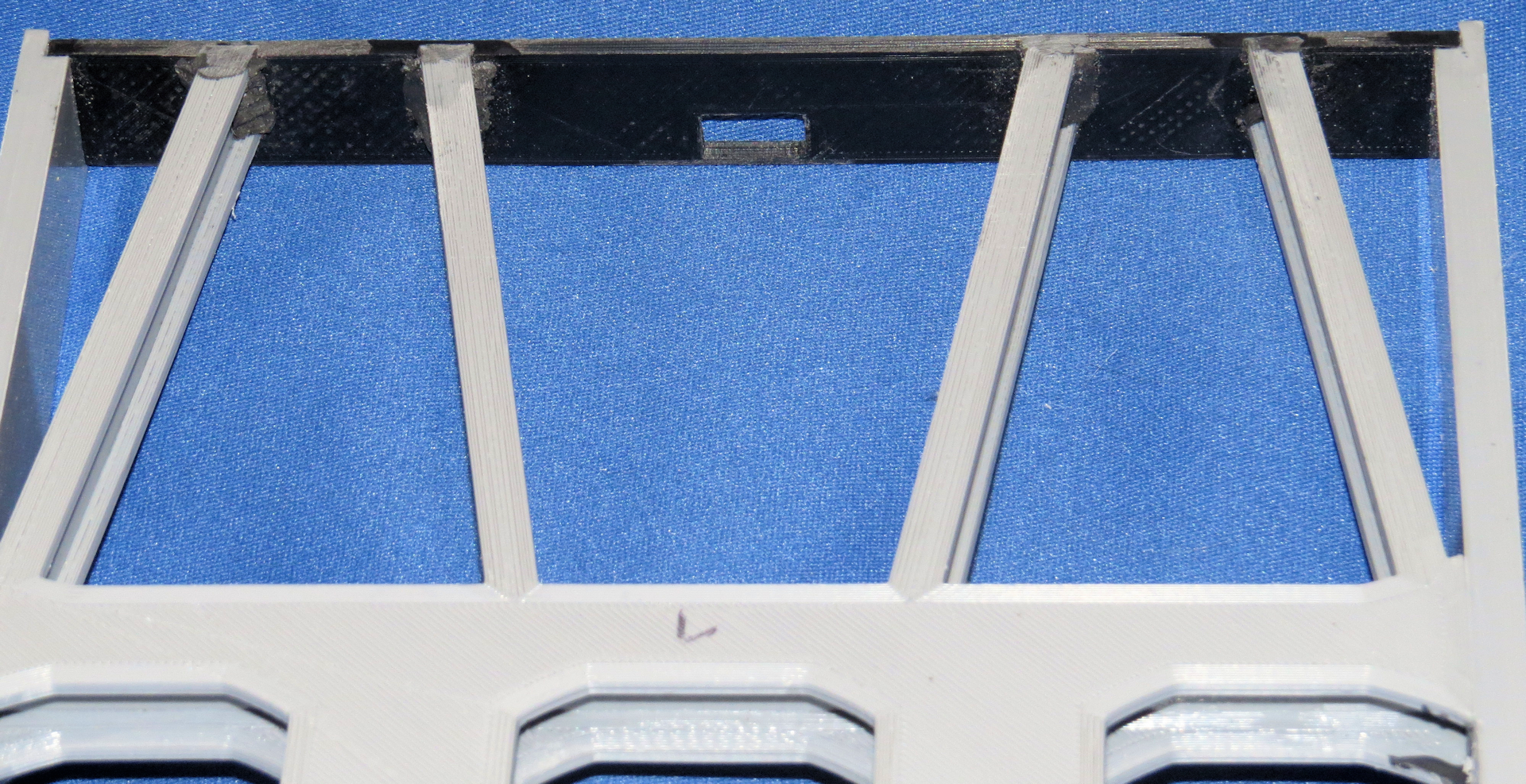
The picture above is where I used the epoxy putty.
I was concerned about the rail car’s ability to hold a 13 lb. RC Tank since it is all just plastic with nowhere near the strength of steel, my solution is I will bond a thin piece of aluminum to the top of the bed so it will work like a stressed skin of an airplane wing and spread the load over the entire bed assembly.

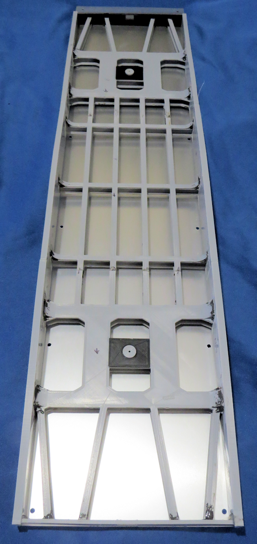
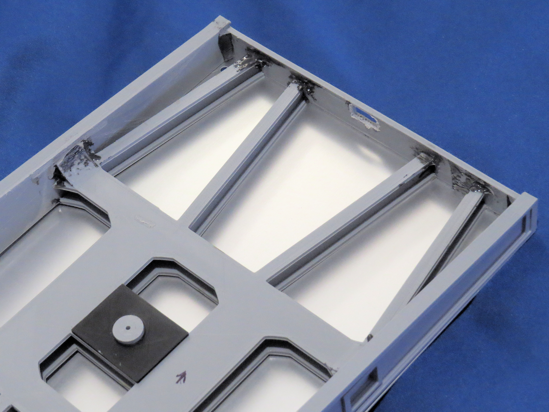
At this point the aluminum plate has not yet been cut to size or mounted to the bed. I have not decided what method to rough up the underside of the aluminum to give it a good bite for the JB Weld, probably sandpaper or scoring it with an Xacto knife blade or likely both.
Once cut and mounted, there will be a printed frame on top of the aluminum plate, which will hold the wood planking in place.
I decided to use bass wood strips instead of balsa wood, as it will hold up better, especially when driving tanks on board with metal tracks.
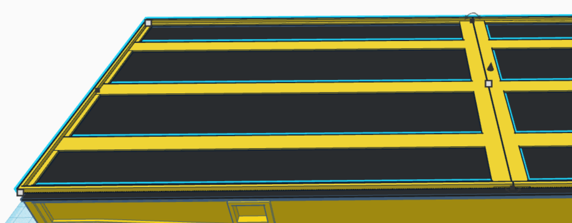
The CAD drawing shows the detail of the top frames and where the planks will rest. I believe I counted 48 planks on the Sabre kit of the SSYMS I purchased, mine may have more or less as I cannot seem to find metric 1/16th scale planks of the correct size at the model train store.
When I install them, depending on the fit I may let them float and use little if any glue to hold them in place.
As long as the planks don't start warping it should be OK. If they start to warp I will have to permanently attach them to the aluminum bed as the plastic frame will not inhibit their warping.
This may be a non-issue as it will primarily be an indoor display stand or used indoors, so humidity would be the only thing to cause warping.
Well that is all for now, next up is the Bogies.
Steve
I can't take credit for the wood grain effect I downloaded it on Thingiverse and cut and sized it to my needs.
I have printed some of the railway ties with that wood grain but most of mine will be actual hardwood with only the plastic ties at key places, it takes a long time to print those in 1/16th scale and considering how many are required there are 40 ties per 65 feet which in 1/16th scale is almost exactly 4 feet which is how long the board the SSYMS will be displayed on, so I will need to make 40 ties.
On the hard wood ties that I use, I will probably cover them with more ballast to hide the fact they do not have the same texture as the printed ties. I am almost certain I do not want to add texture to 32 ties that are mostly hidden under the SSYMS wagon.
When I designed the printed ties I am using, I hedged my bets I made some with the track chairs built in and some without, on those I did provide a depression for the chairs to sit, in order to keep the proper rail spacing, after all I don't want a derailment.
Back to the build.
My next assembly step was to attach the main “I” Beam grid structure together, again there is piano wire inside the beams towards the ends where they are joined, for alignment and strength.
I then bonded the assembled sides to the center grid structure. Lastly I bonded the end plates to the sides and the grid structure.
Additionally I added JB Weld to reinforce the structures at specific joint locations. The epoxy was a little runny so controlling where it went was a little difficult, I had to clean off the excess by filing it away after it had completely hardened.
I also tried some plastic epoxy putty at several locations this was much easier to apply exactly where I wanted it, once painted it will all be invisible to the eye.
Underside of bed with slip sheets around posts and JB Weld at joints.
It is not pretty but once painted black it will be invisible, since it is underneath.
The picture above is where I used the epoxy putty.
I was concerned about the rail car’s ability to hold a 13 lb. RC Tank since it is all just plastic with nowhere near the strength of steel, my solution is I will bond a thin piece of aluminum to the top of the bed so it will work like a stressed skin of an airplane wing and spread the load over the entire bed assembly.
At this point the aluminum plate has not yet been cut to size or mounted to the bed. I have not decided what method to rough up the underside of the aluminum to give it a good bite for the JB Weld, probably sandpaper or scoring it with an Xacto knife blade or likely both.
Once cut and mounted, there will be a printed frame on top of the aluminum plate, which will hold the wood planking in place.
I decided to use bass wood strips instead of balsa wood, as it will hold up better, especially when driving tanks on board with metal tracks.
The CAD drawing shows the detail of the top frames and where the planks will rest. I believe I counted 48 planks on the Sabre kit of the SSYMS I purchased, mine may have more or less as I cannot seem to find metric 1/16th scale planks of the correct size at the model train store.
When I install them, depending on the fit I may let them float and use little if any glue to hold them in place.
As long as the planks don't start warping it should be OK. If they start to warp I will have to permanently attach them to the aluminum bed as the plastic frame will not inhibit their warping.
This may be a non-issue as it will primarily be an indoor display stand or used indoors, so humidity would be the only thing to cause warping.
Well that is all for now, next up is the Bogies.
Steve
Last edited by Shark27; 08-25-2021 at 03:53 PM.
The following users liked this post:
Will01Capri (08-26-2021)
08-26-2021, 09:43 AM
#62
Senior Member
Love it.
Iam working on my own 1/16 garden railway and have been looking to do something similar. I love the work and dedication.
I am mad enough hehe, but designing some other things first lol
Iam working on my own 1/16 garden railway and have been looking to do something similar. I love the work and dedication.
I am mad enough hehe, but designing some other things first lol
08-26-2021, 01:20 PM
#63
Thread Starter
If you plan on doing one in the future you might verify the curves on the garden railway you already have are not too small a radius for this car. Taking in to account that this scale is somewhat larger than "G" scale 1/16th vs 1/20th,1/22.5, 1/24th "G" scale (pick one) and due to the length of the bogies and the fact they are nestled under the bed frame they have a somewhat limited travel and cannot negotiate tight turns.
I haven't done the math or laid it out on a large enough area to see how tight a radius it can actually negotiate. I looked up "G" scale turn radius and it looks like 24" to 44" is the range offered, the larger should work fine, not sure about the smaller.
I have picked up some "G" scale track for testing, I'll let you know what I find out when I layout some curve sections.
One other thing if you were to run one of these on your Garden railway, make your coupler hook out of brass or some other metal, as it will have all the stress on it once the car is loaded with a 10 to 20 lb. RC Tank, the mount should probably be OK.
Steve
The following users liked this post:
Will01Capri (08-27-2021)
08-28-2021, 07:45 PM
#64
Thread Starter
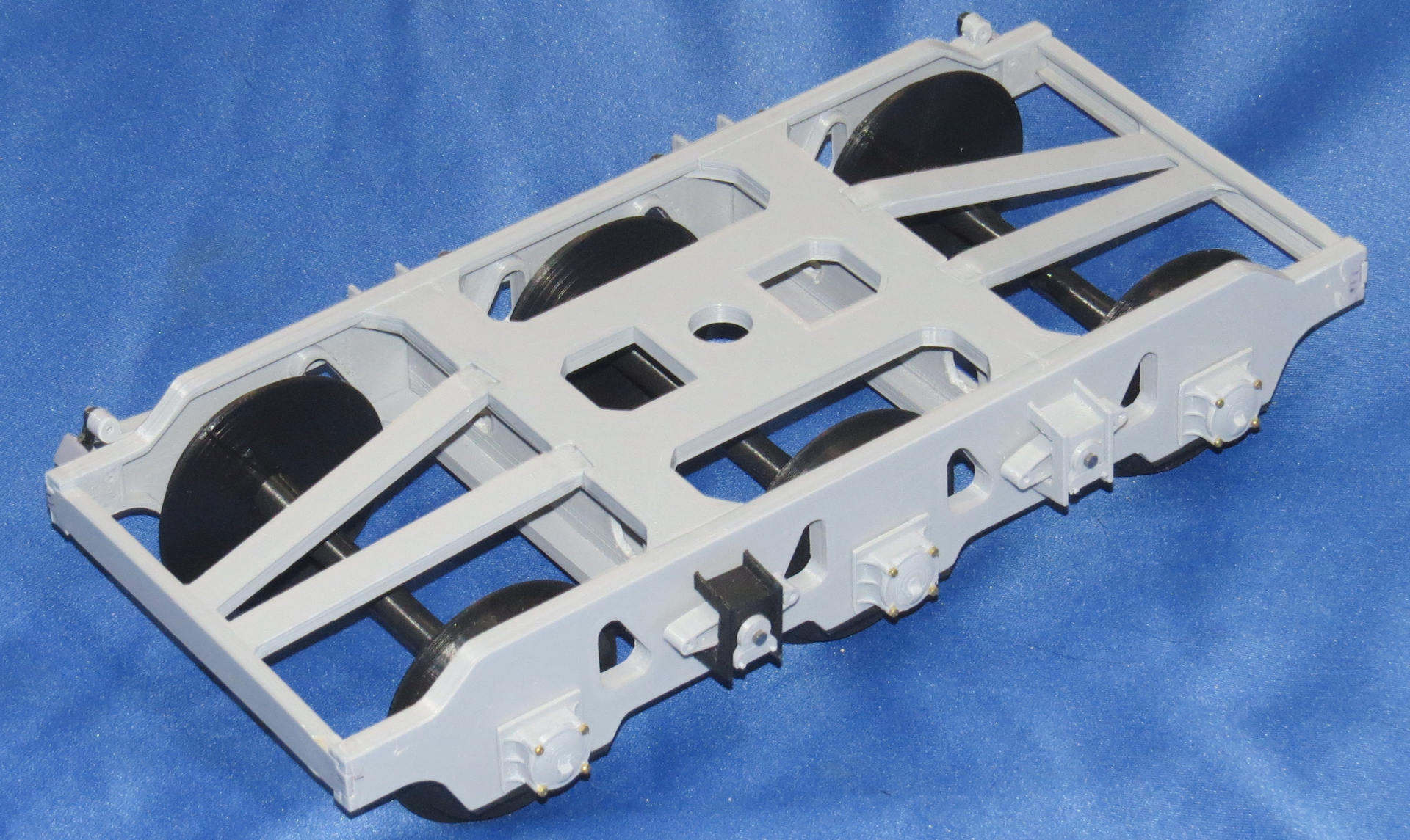
Next up was to tackle the bogies, there are many parts to the bogies due to the suspension components.
I actually assembled one of the bogies a while ago, not with details just the main framework axle boxes wheels and axles.
It was necessary to verify the design would work, since this was the first thing I had totally designed from scratch and had changed somewhat since I decided to do the suspension components and replace the straight axles with the tapered units.
The bogies went together as expected everything was bonded together, luckily my interlocking design is somewhat self-aligning so everything is pretty much already square. I used rubber bands and inexpensive clamps to make sure everything was tight before applying glue.
I then installed the wheels, axles and inner axle box assemblies and the lower plates that hold them in place, the redesigned axles have a big advantage over the straight axles I printed previously, the wheels are already perpendicular to the axle since they rest up against the shoulder I created on the axle.
On the straight axles the wheels would slide up and down the axles, it was necessary to create a jig to get them squared to the axles and to be the correct spread between the wheels to fit the 1/16th scaled track I had created.
The disadvantage is I will have to print different axles to fit the �G� scale track in Danville as that track width is quite different.

I started attaching the suspension components on this one.
Onto the suspension detail, I originally decided to use Hex head bolts to join the suspension components together for disassembly purposes, but as it turns out I only had enough for one side, so I decided to go with Button Head screws in black instead.
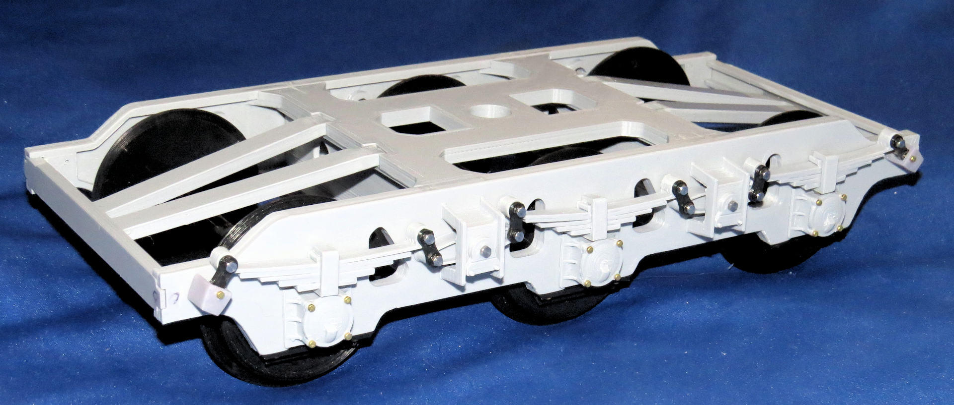
On the second set of bogies I may just use pins glued in place to hold everything together, that is how the real suspension was held in place with pins and very large horseshoe clips.

Most of the detail is just for show, although it is designed to be functional with plastic leaf springs it cannot support the weight of the rail car and the 13 lb. tank on top.
You may have noticed that only the outside links are in place on the suspension components the inside links not being necessary since it is just for show anyway I left them off, once painted flat black and buried under the bed it will be mostly unseen.
Also yet to be added is the alignment pins in the bottom of the leaf spring set that keeps them lined up with the axle boxes below.
One major detail I omitted on the bogies is the braking system, it was fairly complex and looked to be a very large PITA and a lot of work designing and printing it. Theoretically it could be added later on, since I made it so the axles can be easily removed, however one would have to make the system somewhat functional so as to allow the brakes to swing out of the way when reinstalling the wheels and axles.
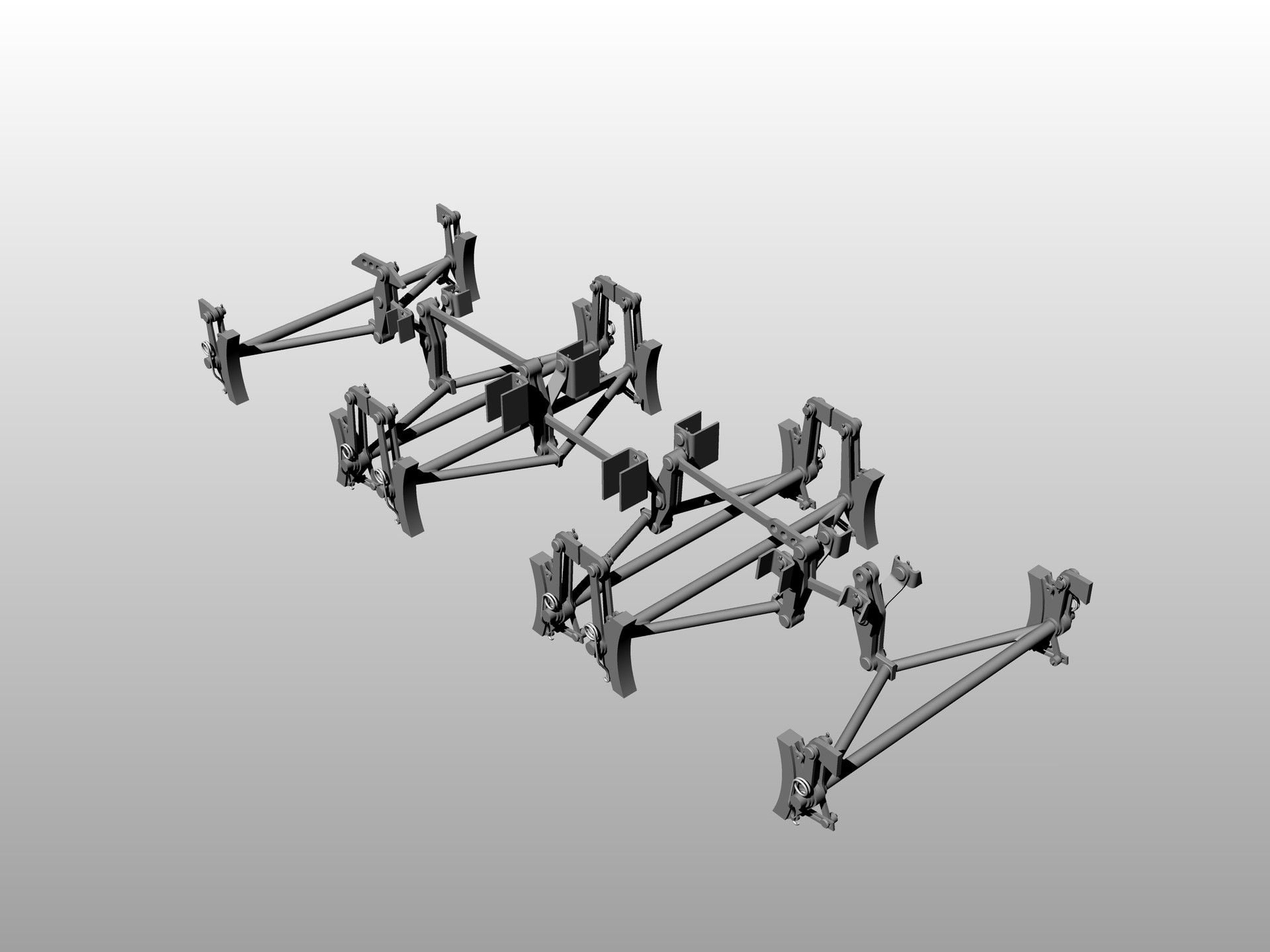
This is actually from a four axle rail car but they are similar. When I designed the suspension parts I knew they would not support the weight of an RC Tank so I limited the travel of the suspension to about 75% of the actual movement it was capable of. So it will look like it is correctly loaded but not bottoming out, which it actually will be.
While I had printed enough parts for the two bogies I ended up printing some additional parts in resin and some in PLA as I went along and made adjustments. I have still yet to print most of the detail parts for the second set of Bogies.
I am definitely a trial and error kind of guy, so it does not benefit me printing all the parts ahead of time, as there are almost always changes to be made or that I will make as I improve things.
It is better printing some parts as I go along and just print the key components that I will not change and that other parts will be adjusted to fit those components.
Many times I will create and print an alternate version of a part to see if the different version works better or worse than the original design. It wastes a little time but saves in the long run.
Common sense tells me it is better to print 12 parts that work well than print 12 that need adjustment or redesign and then print 12 more of the corrected part or rework the incorrect parts with files or whatever.
Sometimes I make more work for myself by adding details or functionality which by way of the ripple effect requires changes to other components.
The coupling hook and mechanism is an example, I did originally design it to look prototypical of the real type used on the real rail car, however, I decided a little late that I would make it swivel like the original unit as well.
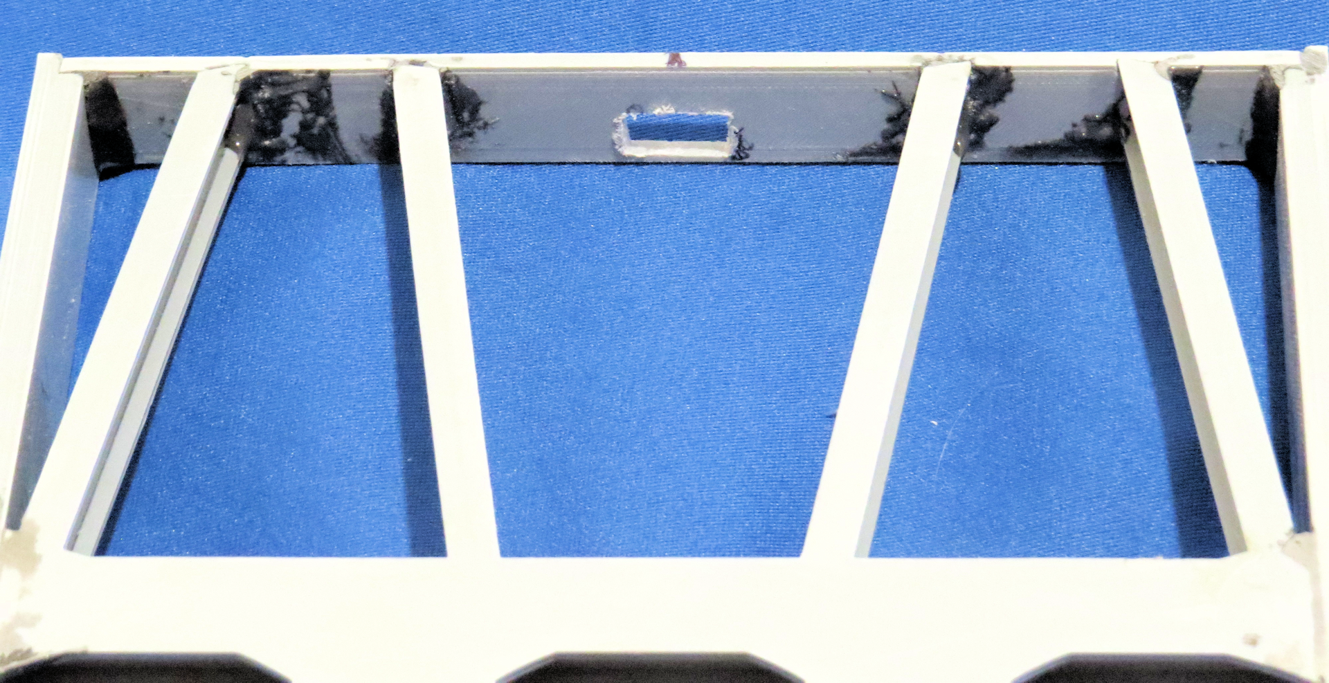
 This required some changes to the hook as well as adding the support structure for that to happen, which meant changing the bed end plate sub plate, which I had already bonded to the sides of the bed.
This my friends is what the Dremel tool was invented for, I enlarged the hole in the sub plate to allow for the newly created mounting mechanism for the swiveling coupler hook, it ain�t pretty but the alternative would be much worse.
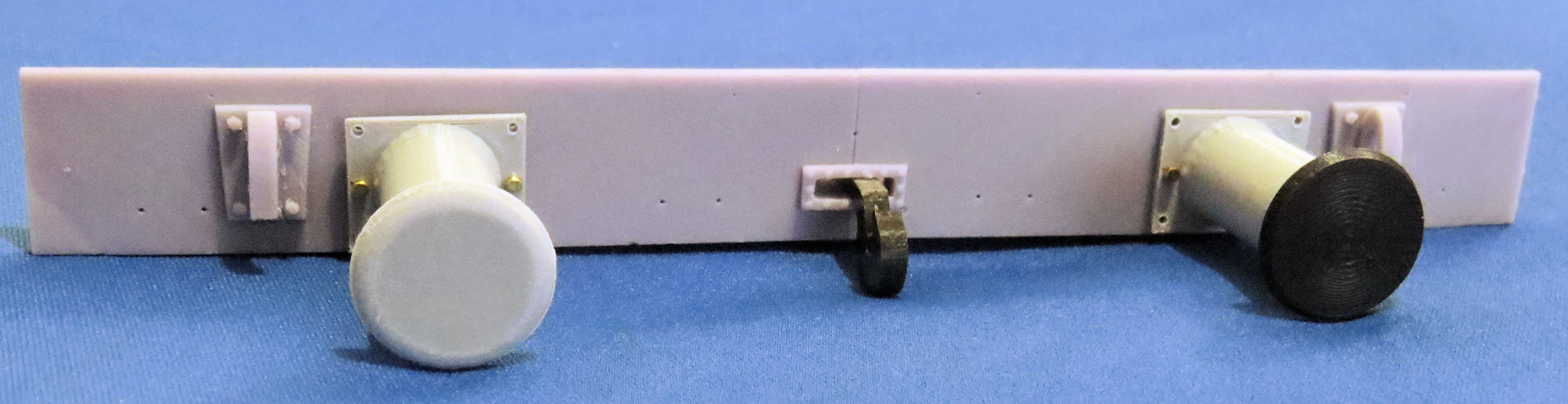
While I was at it I decided to try to resin print the end plate that the hook passes through, with all the additional parts as a complete unit. As you can see there are many parts attached to the end plate especially the endplate that has the folding handrail.
You may have noticed one of the endplate was two pieces joined together, I was unsure at the time that I could print the entire endplate as one piece as it is longer than the build plate on my resin printer.
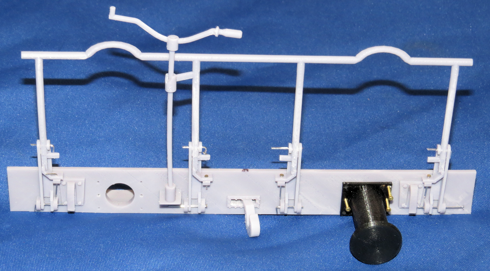
Handrail erect, pins holding everything in place temporarily This is a resin print of the handrail assembly, the handrail mounts and all of the detail was printed as one part only the handrail movable parts and buffers are added.

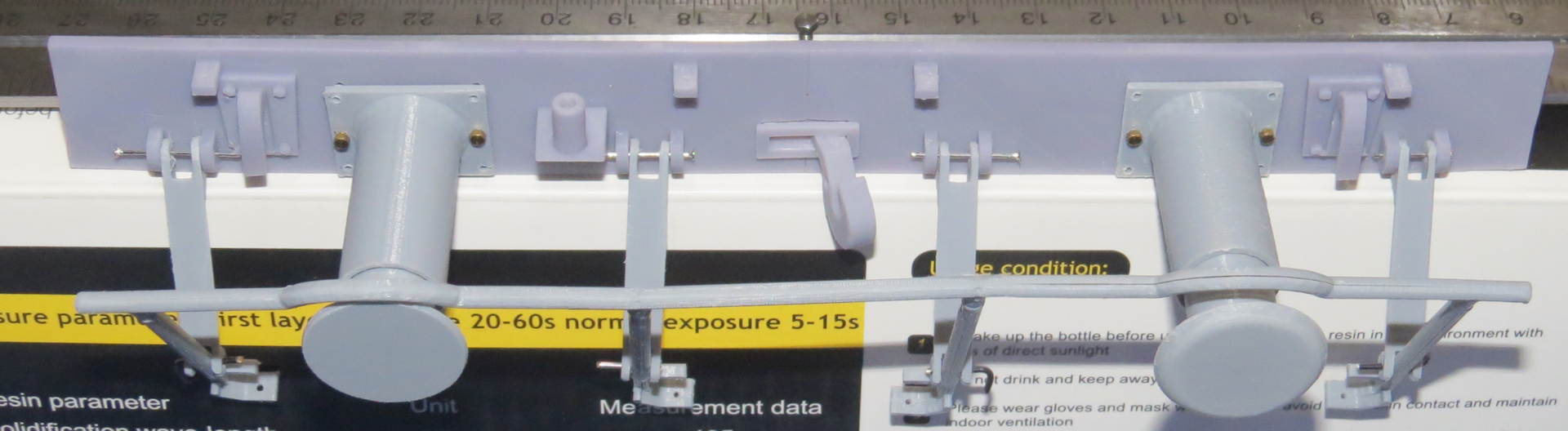
Handrail folded, Buffers are uneven as the springs are yet to be installed
This is the non-handrail endplate there was only one handrail on the rail car

From the Sabre manual showing the handrail folded.
I opted not to print the buffers as part of the endplate the buffers are printed in PLA for now I may reprint them in ABS or ASA later on depending on how well the PLA holds up, I knew they may get damaged during use, so I made these easily replaceable as is the entire endplate, since it is held in place by the bolts holding the buffers in position.
So all the component parts included as part of the resin endplate are the eight mounts for the folding handrail upright stanchions and locking tabs as well as the inverted hooks for the tow cables and the base for the braking handle in addition to the new coupler mount.
The original bed that I designed and printed has no accommodation for the swiveling coupler mount so I will rework the ends to accommodate the endplates with the coupler mounts.
In case anyone was curious as to why so long between posts, I have been working on several other project while doing this one, here are pics of some of my other projects.
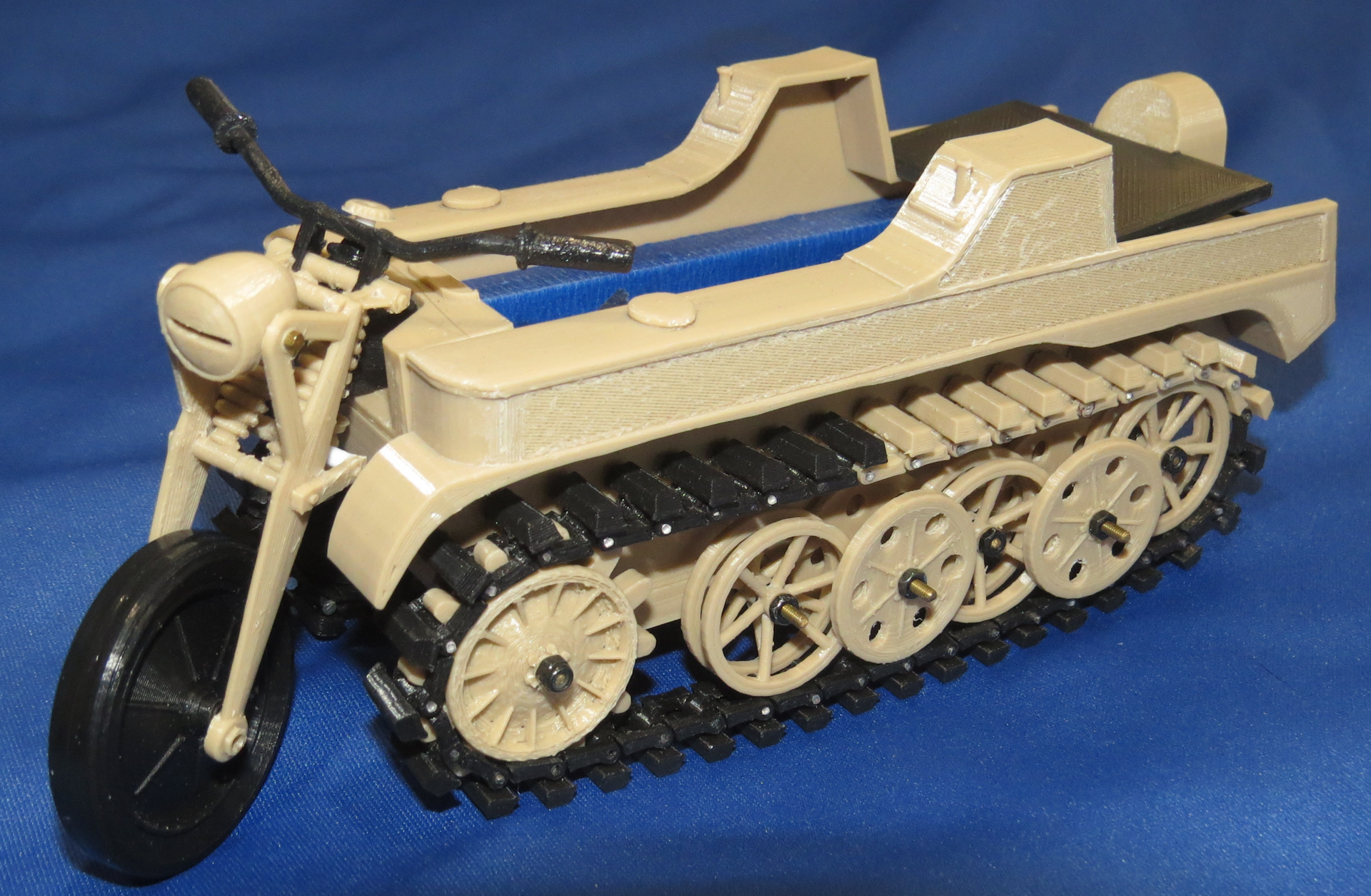
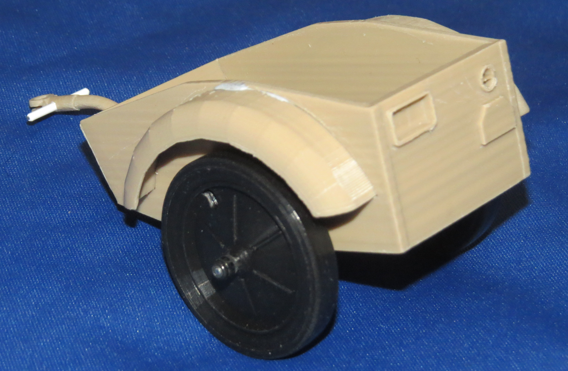

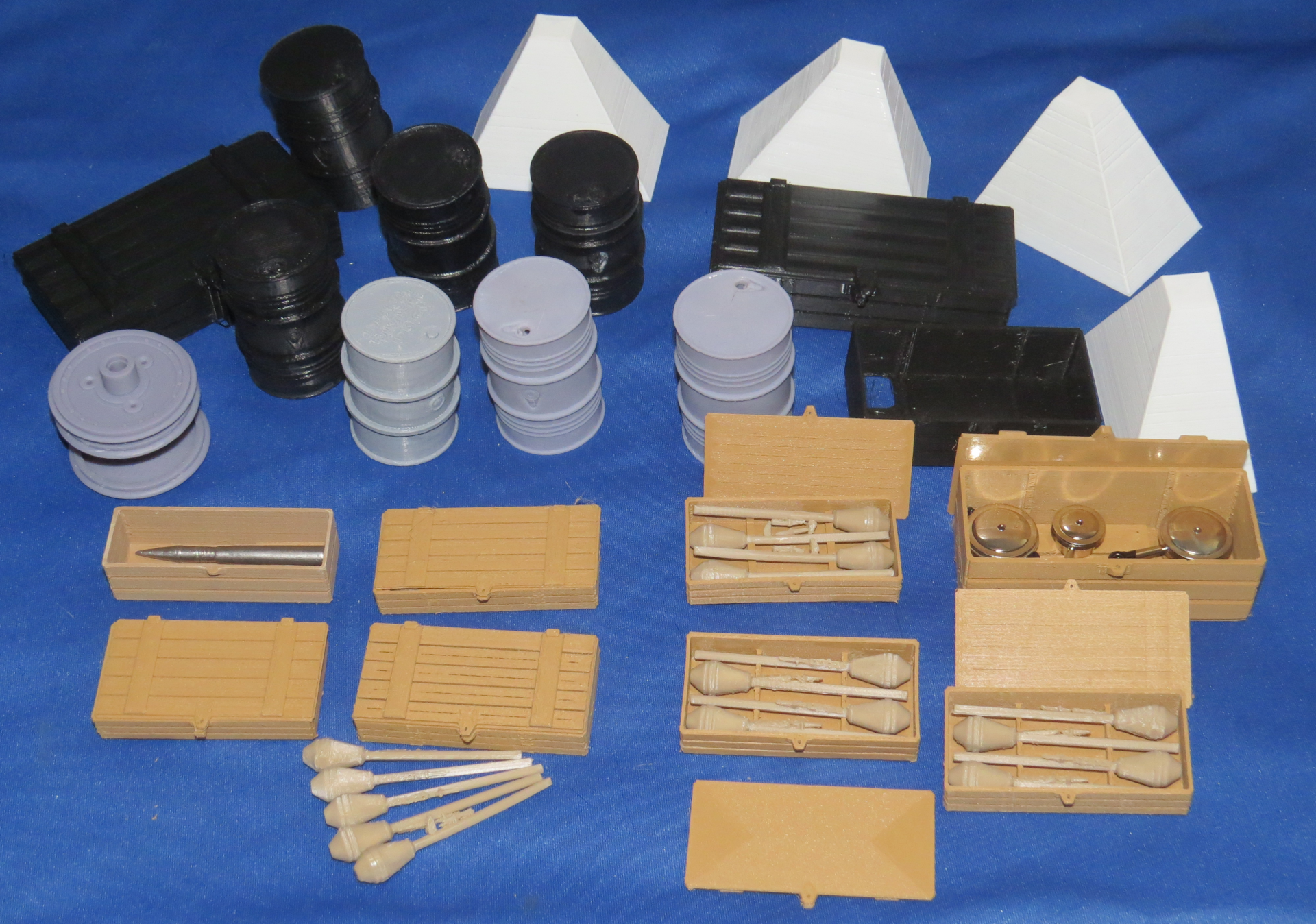

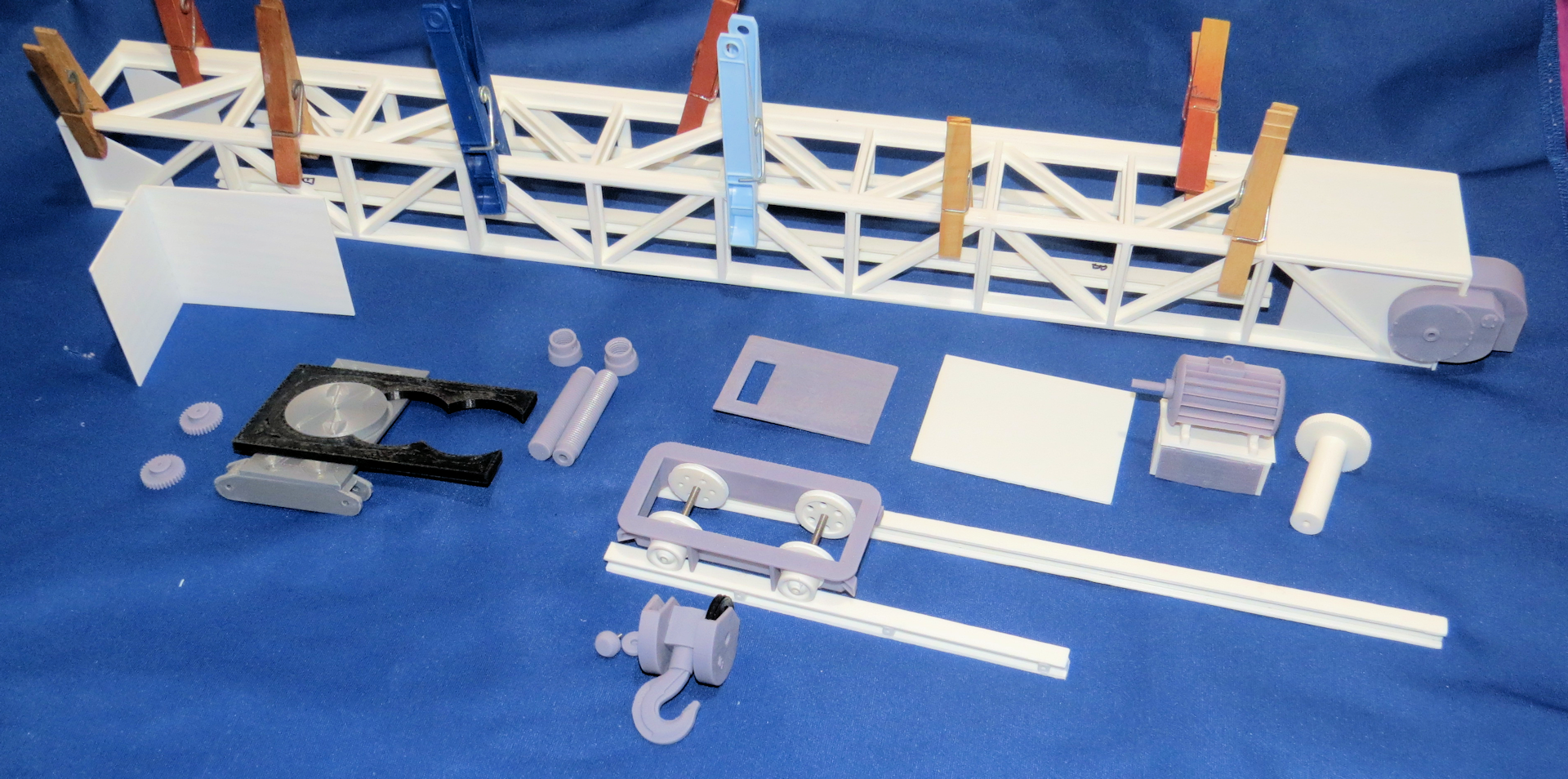
Some of these are nearing completion.
All for now
I actually assembled one of the bogies a while ago, not with details just the main framework axle boxes wheels and axles.
It was necessary to verify the design would work, since this was the first thing I had totally designed from scratch and had changed somewhat since I decided to do the suspension components and replace the straight axles with the tapered units.
The bogies went together as expected everything was bonded together, luckily my interlocking design is somewhat self-aligning so everything is pretty much already square. I used rubber bands and inexpensive clamps to make sure everything was tight before applying glue.
I then installed the wheels, axles and inner axle box assemblies and the lower plates that hold them in place, the redesigned axles have a big advantage over the straight axles I printed previously, the wheels are already perpendicular to the axle since they rest up against the shoulder I created on the axle.
On the straight axles the wheels would slide up and down the axles, it was necessary to create a jig to get them squared to the axles and to be the correct spread between the wheels to fit the 1/16th scaled track I had created.
The disadvantage is I will have to print different axles to fit the �G� scale track in Danville as that track width is quite different.
I started attaching the suspension components on this one.
Onto the suspension detail, I originally decided to use Hex head bolts to join the suspension components together for disassembly purposes, but as it turns out I only had enough for one side, so I decided to go with Button Head screws in black instead.
On the second set of bogies I may just use pins glued in place to hold everything together, that is how the real suspension was held in place with pins and very large horseshoe clips.
Most of the detail is just for show, although it is designed to be functional with plastic leaf springs it cannot support the weight of the rail car and the 13 lb. tank on top.
You may have noticed that only the outside links are in place on the suspension components the inside links not being necessary since it is just for show anyway I left them off, once painted flat black and buried under the bed it will be mostly unseen.
Also yet to be added is the alignment pins in the bottom of the leaf spring set that keeps them lined up with the axle boxes below.
One major detail I omitted on the bogies is the braking system, it was fairly complex and looked to be a very large PITA and a lot of work designing and printing it. Theoretically it could be added later on, since I made it so the axles can be easily removed, however one would have to make the system somewhat functional so as to allow the brakes to swing out of the way when reinstalling the wheels and axles.
This is actually from a four axle rail car but they are similar. When I designed the suspension parts I knew they would not support the weight of an RC Tank so I limited the travel of the suspension to about 75% of the actual movement it was capable of. So it will look like it is correctly loaded but not bottoming out, which it actually will be.
While I had printed enough parts for the two bogies I ended up printing some additional parts in resin and some in PLA as I went along and made adjustments. I have still yet to print most of the detail parts for the second set of Bogies.
I am definitely a trial and error kind of guy, so it does not benefit me printing all the parts ahead of time, as there are almost always changes to be made or that I will make as I improve things.
It is better printing some parts as I go along and just print the key components that I will not change and that other parts will be adjusted to fit those components.
Many times I will create and print an alternate version of a part to see if the different version works better or worse than the original design. It wastes a little time but saves in the long run.
Common sense tells me it is better to print 12 parts that work well than print 12 that need adjustment or redesign and then print 12 more of the corrected part or rework the incorrect parts with files or whatever.
Sometimes I make more work for myself by adding details or functionality which by way of the ripple effect requires changes to other components.
The coupling hook and mechanism is an example, I did originally design it to look prototypical of the real type used on the real rail car, however, I decided a little late that I would make it swivel like the original unit as well.
This required some changes to the hook as well as adding the support structure for that to happen, which meant changing the bed end plate sub plate, which I had already bonded to the sides of the bed.This my friends is what the Dremel tool was invented for, I enlarged the hole in the sub plate to allow for the newly created mounting mechanism for the swiveling coupler hook, it ain�t pretty but the alternative would be much worse.
While I was at it I decided to try to resin print the end plate that the hook passes through, with all the additional parts as a complete unit. As you can see there are many parts attached to the end plate especially the endplate that has the folding handrail.
You may have noticed one of the endplate was two pieces joined together, I was unsure at the time that I could print the entire endplate as one piece as it is longer than the build plate on my resin printer.
Handrail erect, pins holding everything in place temporarily This is a resin print of the handrail assembly, the handrail mounts and all of the detail was printed as one part only the handrail movable parts and buffers are added.
Handrail folded, Buffers are uneven as the springs are yet to be installed
This is the non-handrail endplate there was only one handrail on the rail car
From the Sabre manual showing the handrail folded.
I opted not to print the buffers as part of the endplate the buffers are printed in PLA for now I may reprint them in ABS or ASA later on depending on how well the PLA holds up, I knew they may get damaged during use, so I made these easily replaceable as is the entire endplate, since it is held in place by the bolts holding the buffers in position.
So all the component parts included as part of the resin endplate are the eight mounts for the folding handrail upright stanchions and locking tabs as well as the inverted hooks for the tow cables and the base for the braking handle in addition to the new coupler mount.
The original bed that I designed and printed has no accommodation for the swiveling coupler mount so I will rework the ends to accommodate the endplates with the coupler mounts.
In case anyone was curious as to why so long between posts, I have been working on several other project while doing this one, here are pics of some of my other projects.
Some of these are nearing completion.
All for now
The following 2 users liked this post by Shark27:
Ex_Pat_Tanker (08-29-2021),
Will01Capri (08-29-2021)
08-29-2021, 07:30 AM
#66
Thread Starter
Martin,
How is your Fries Crane coming along?
I saw someone (Tigerfan) on the (RC Tank Warfare) forum working on one as well, his are now finished, he built four of them at once, it looks like he may be selling some of them. I copied his electric motor design when I did mine. The 3D model of the electric motor is big enough to put an actual electric motor inside, which I might do at some point. I would have to design and print the complete drive train for the crane and the generator the Germans used to house the battery.
He painted his in dark gray, I think I will do a late war camouflage when I paint mine or at least dark yellow.
Steve
08-29-2021, 07:40 AM
#67
Mine has stalled out due to having too many other projects. My recent experience with first ABS and then PETG on the Bailey bridge suggests that I might struggle to print it at the quality level I want, and glue it together well enough that it will be transportable.
Printing and assembling it in PLA would be easy, but there's not enough structure there for me to have confidence that it wouldn't sag under its own weight the first time I left it out in the summer sun at a show.
Printing and assembling it in PLA would be easy, but there's not enough structure there for me to have confidence that it wouldn't sag under its own weight the first time I left it out in the summer sun at a show.
08-29-2021, 08:20 AM
#68
Thread Starter
Mine has stalled out due to having too many other projects. My recent experience with first ABS and then PETG on the Bailey bridge suggests that I might struggle to print it at the quality level I want, and glue it together well enough that it will be transportable.
Printing and assembling it in PLA would be easy, but there's not enough structure there for me to have confidence that it wouldn't sag under its own weight the first time I left it out in the summer sun at a show.
Printing and assembling it in PLA would be easy, but there's not enough structure there for me to have confidence that it wouldn't sag under its own weight the first time I left it out in the summer sun at a show.
You might try ASA filament it seems to hold up in higher temps and less warping on the print bed than ABS, also less toxic fumes.
It looks like mine will be indoors, so the sun may not be a problem, it's only the tankers that melt from the heat here in Florida.
 08-29-2021, 12:49 PM
#69
Like ASA is just as toxic as ABS as far as I can tell, which means that its only something I can use during the month of July when its warm enough to print with the patio door open - I don't have a separate room I can put the printers in, so they have to sit in my living room.
08-29-2021, 02:54 PM
#71
Its was 2 things mainly - crispness of the detail compared with PLA (and a lot of 'candy floss' everywhere in general), and the brittle nature of the material making support material awkward to remove without breaking the print.
Compared with ABS it stuck to the print bed really well, and paint adhesion hasn't been an issue so far (I used a dedicated adhesion promoter before using an Auto body primer, which probably helped). It seemed to make a lot of fine dust everywhere while printing, which wasn't great, and its very brittle compared with PLA - drilling or dropping parts while I was cleaning them up resulted in breakages.
Compared with ABS it stuck to the print bed really well, and paint adhesion hasn't been an issue so far (I used a dedicated adhesion promoter before using an Auto body primer, which probably helped). It seemed to make a lot of fine dust everywhere while printing, which wasn't great, and its very brittle compared with PLA - drilling or dropping parts while I was cleaning them up resulted in breakages.
09-10-2021, 12:07 AM
#72
Thread Starter
Martin,
I had similar experience with the PETG, I believe I wasn't printing it hot enough for it to work well. I have read it can be difficult to dial in printers to print it well.
Update:
I finally finished assembling one of the bogies completely.
Not wanting to leave well enough alone, I made two changes to the SSYMS 80 ton rail car which impacted some other components of course.
Firstly, I changed my mind and decided to make the suspension mirror the real rail car. Which meant using pins instead of screws to hold everything together.
There were several reasons behind this, one reason was the suspension was not in the correct position to contact the axle boxes in the right place the leaf springs were too close to the bogie side plates.
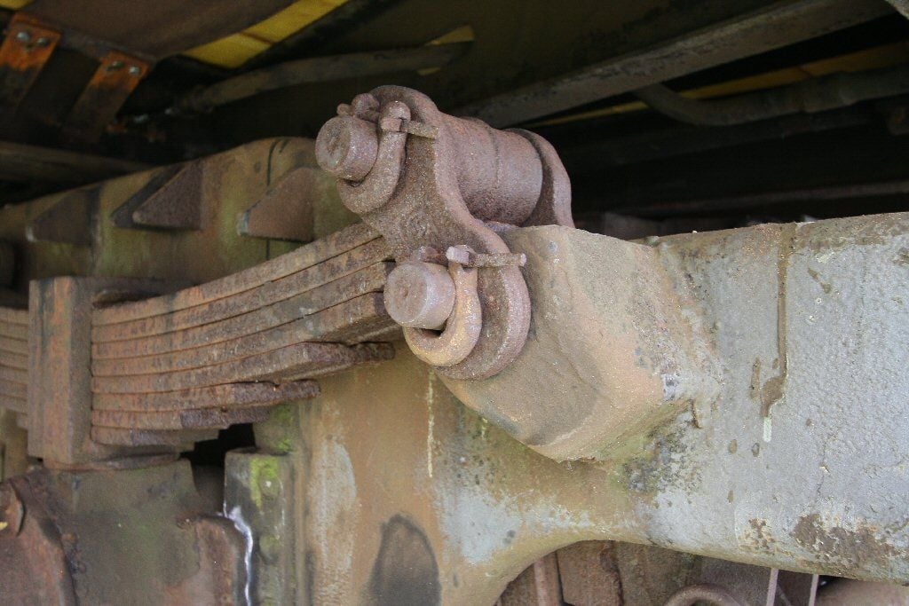
On the real suspension they had recesses manufactured into the bogie side plates (on some) which allowed them to use pins and “C” clips that slid into recesses cut into the pins and kept it from moving. On one of the pictures I posted of the real suspension you can see it.
Due to limitations in FDM 3D printing I could not duplicate the recesses in the bogie side plates, besides I had already printed and assembled the bogies and wanted to use what I had printed.
So I basically did it without the recesses.
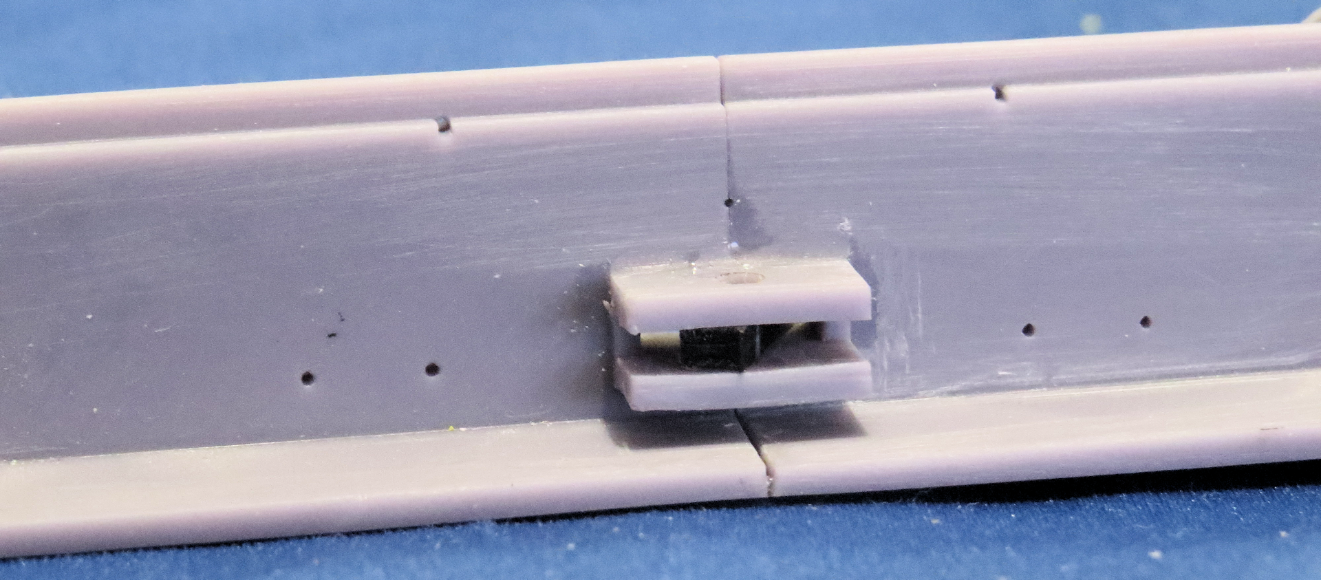
I had already printed up a bunch of the small links that join the suspension components. I printed two styles one with a raised shoulder around the holes on one side and one without any shoulders at all.
Unfortunately the links without shoulders were still too thick to fit between the backside of the leaf springs and toggle pieces and allow any movement of the suspension.
My solution was simple, I just printed 32 thinner links to go behind the leaf springs and toggle parts. I made the pins out of 1.75mm 3D printing filament, inserted into the holes in the links and glued into position, I left them longer than required, so I could more easily work with them.
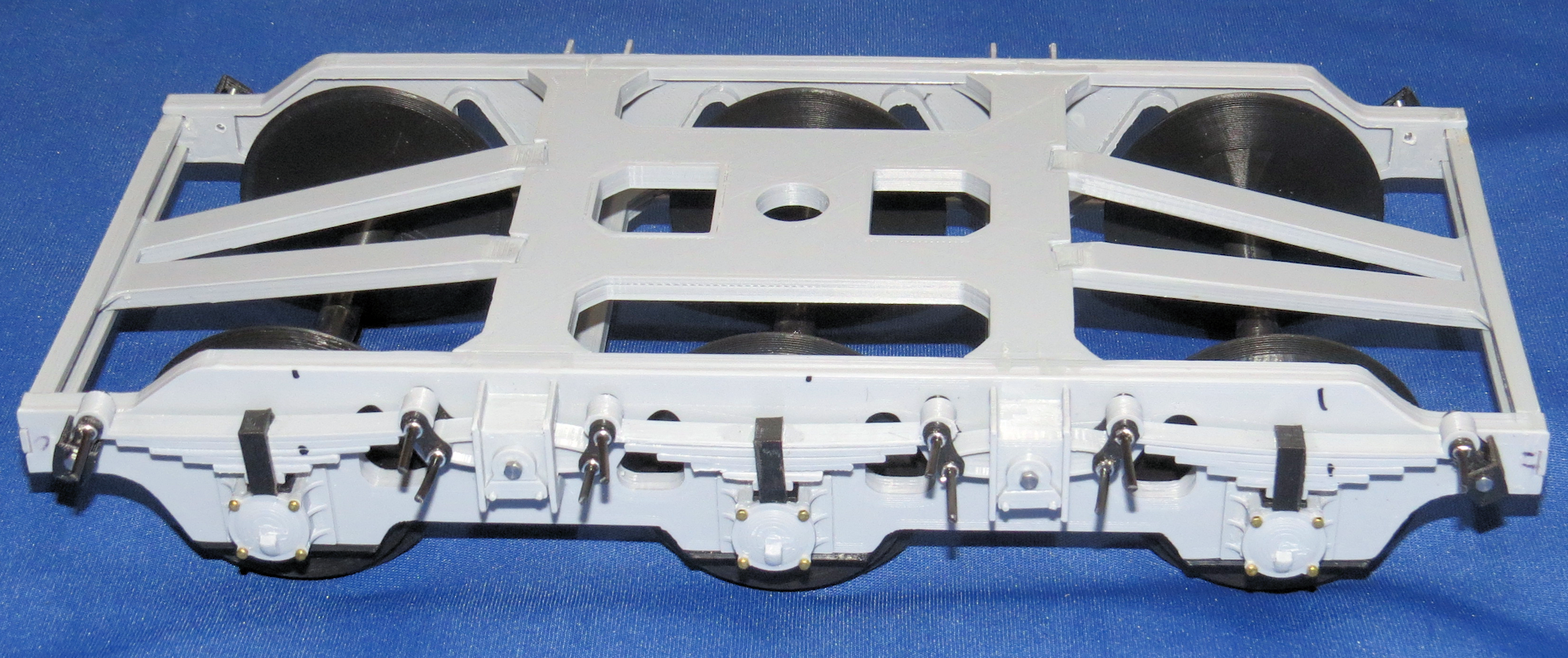
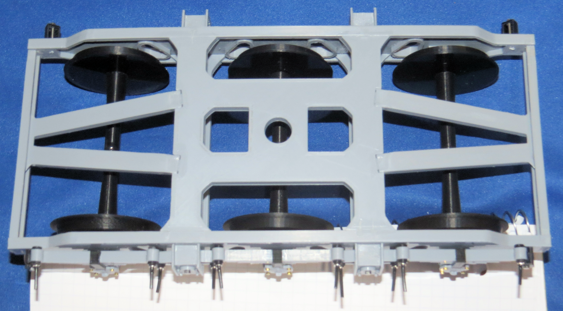
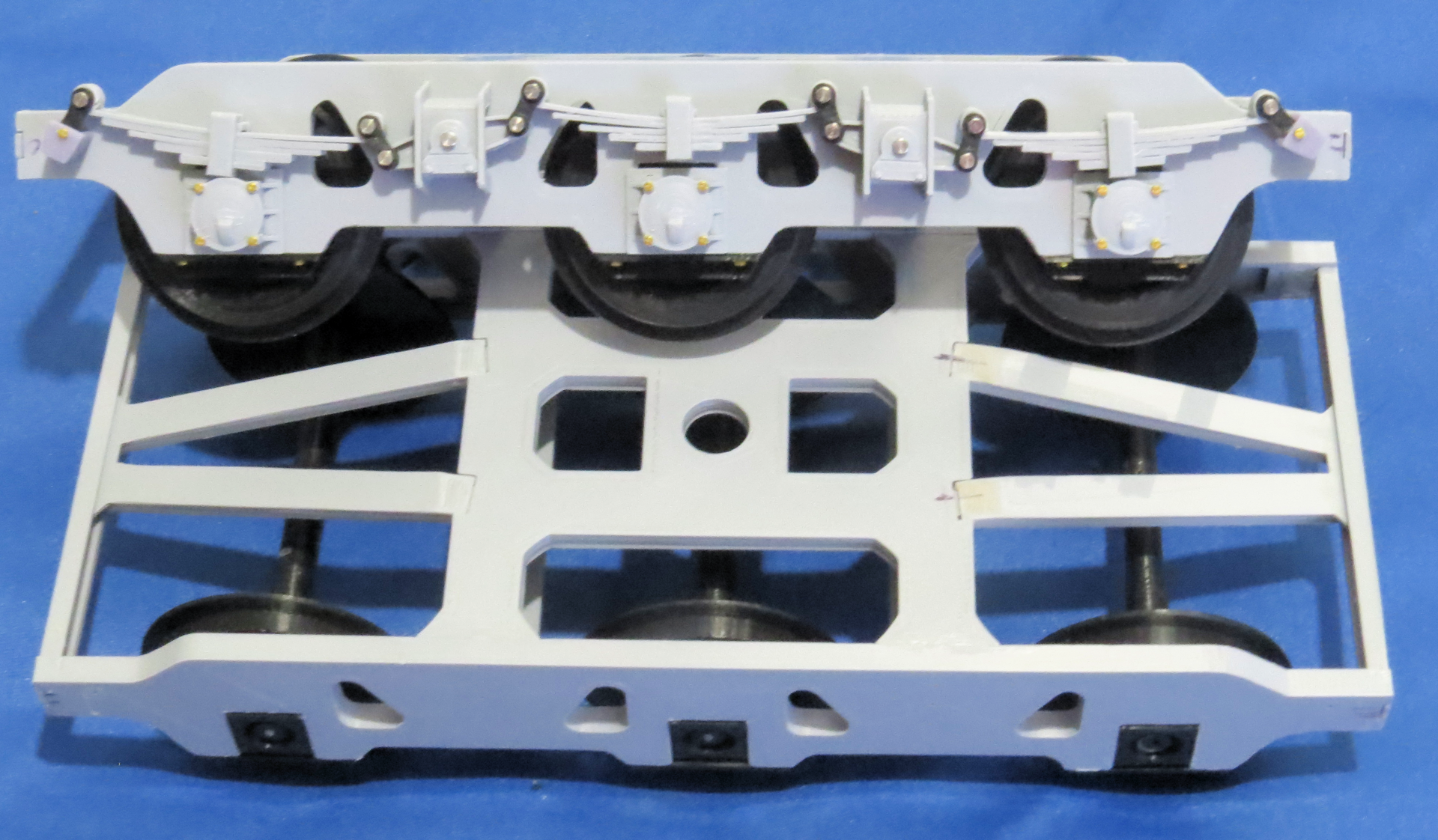
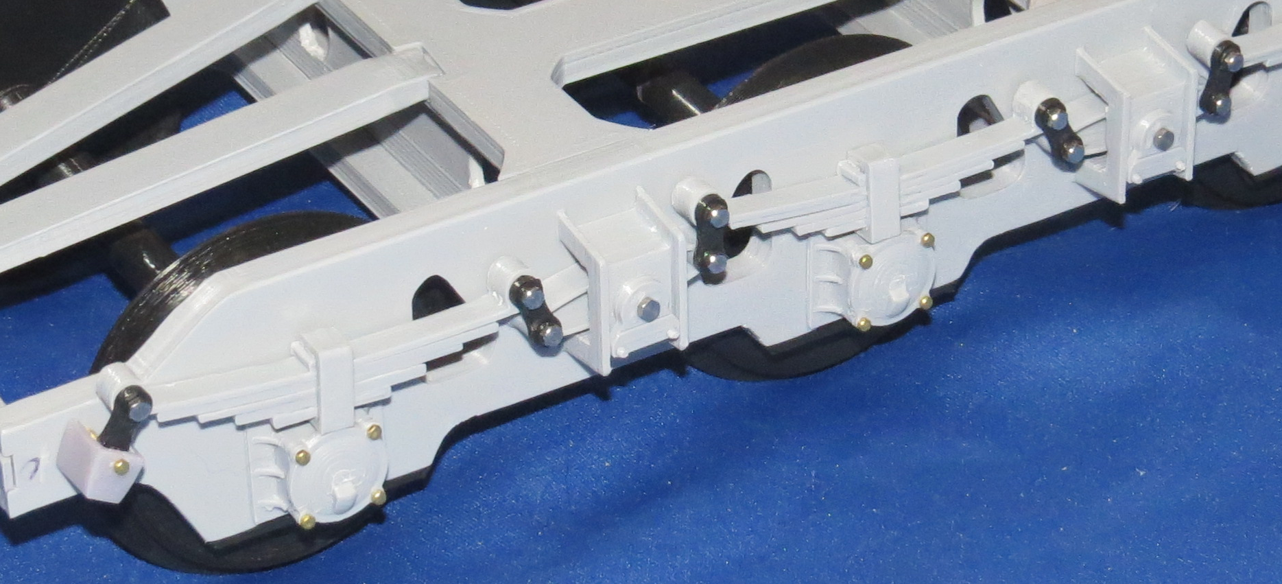
This picture shows the links behind the suspension components.

The picture above shows the links with the pins that fit behind the leaf spring and toggles.
I was not going to be able to notch the filament pins to allow any kind of “C” clip to hold things together, I had some straight pins with eye holes on one end and it turns out they were just the right diameter to fit over the PLA pins. I cut off the excess straight pin and glued them into position, so at least it looks similar to what the Germans did when they built these rail cars.
I leave it for you to judge. From ten feet away you could never tell.
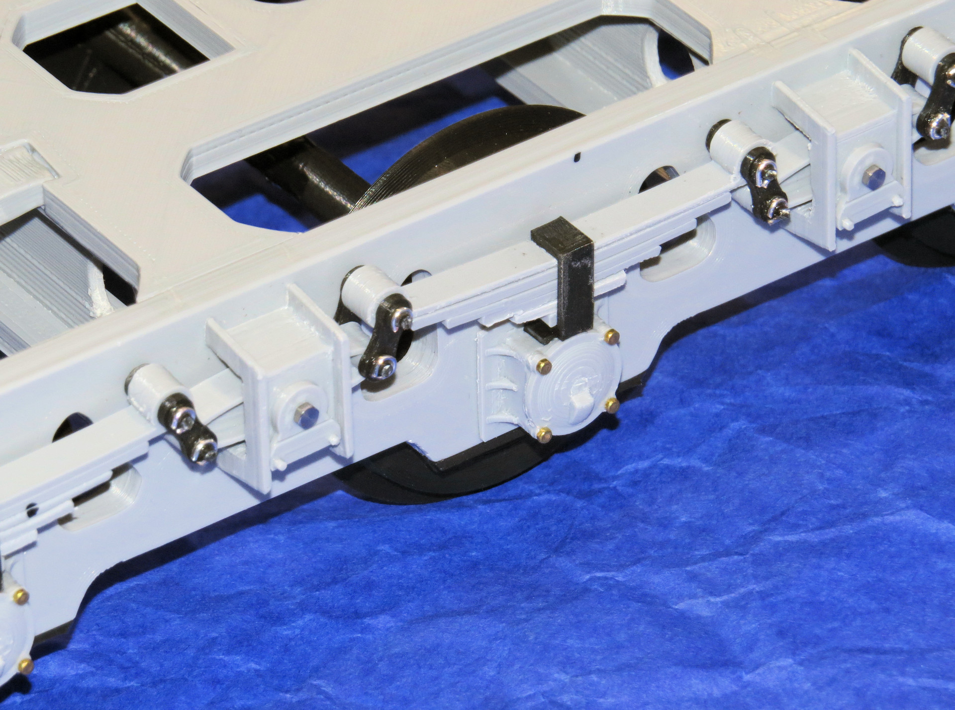
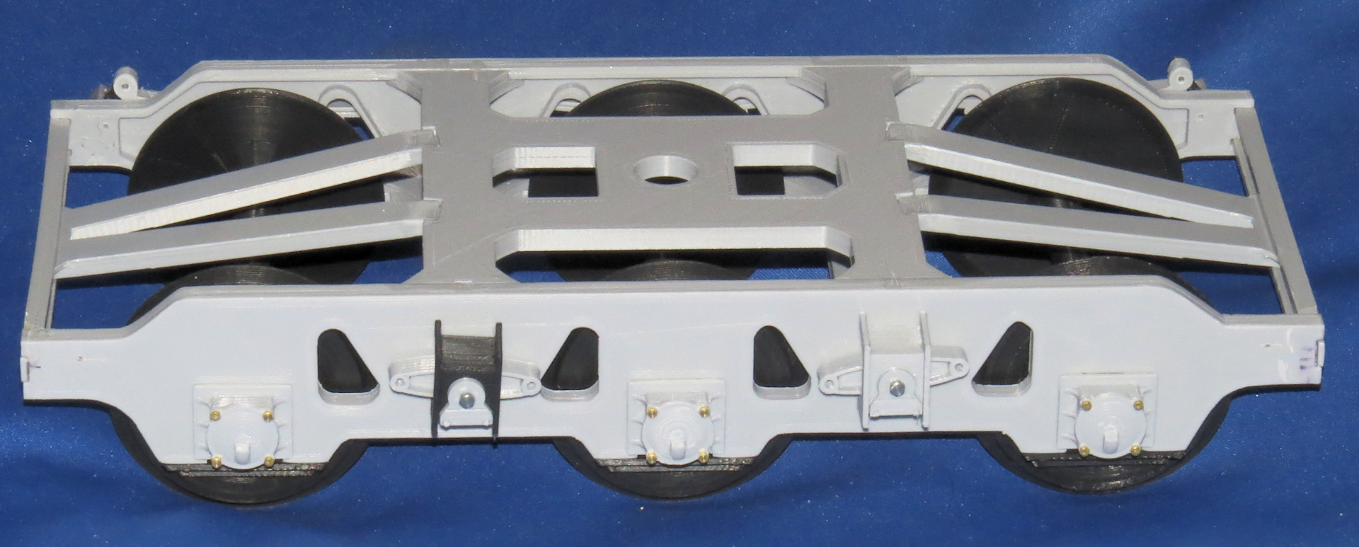
The middle of the bogie with everything attached.
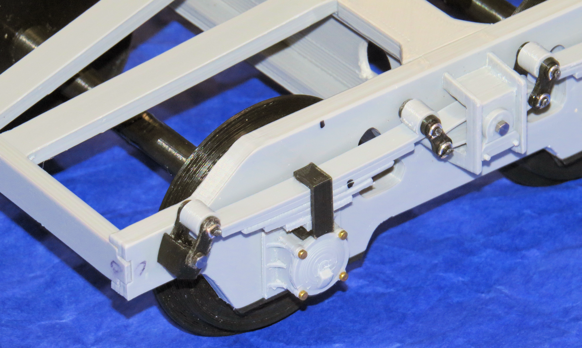
The end of the same bogie showing end attachment for the leaf spring.
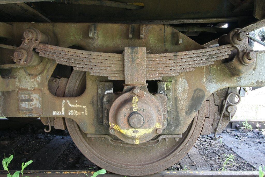
Above, the real rail car suspension, (a later or updated version), mine won't look this rusty when done and mine won't have any brakes! Yikes!
All for now!
Steve
I had similar experience with the PETG, I believe I wasn't printing it hot enough for it to work well. I have read it can be difficult to dial in printers to print it well.
Update:
I finally finished assembling one of the bogies completely.
Not wanting to leave well enough alone, I made two changes to the SSYMS 80 ton rail car which impacted some other components of course.
Firstly, I changed my mind and decided to make the suspension mirror the real rail car. Which meant using pins instead of screws to hold everything together.
There were several reasons behind this, one reason was the suspension was not in the correct position to contact the axle boxes in the right place the leaf springs were too close to the bogie side plates.
On the real suspension they had recesses manufactured into the bogie side plates (on some) which allowed them to use pins and “C” clips that slid into recesses cut into the pins and kept it from moving. On one of the pictures I posted of the real suspension you can see it.
Due to limitations in FDM 3D printing I could not duplicate the recesses in the bogie side plates, besides I had already printed and assembled the bogies and wanted to use what I had printed.
So I basically did it without the recesses.
I had already printed up a bunch of the small links that join the suspension components. I printed two styles one with a raised shoulder around the holes on one side and one without any shoulders at all.
Unfortunately the links without shoulders were still too thick to fit between the backside of the leaf springs and toggle pieces and allow any movement of the suspension.
My solution was simple, I just printed 32 thinner links to go behind the leaf springs and toggle parts. I made the pins out of 1.75mm 3D printing filament, inserted into the holes in the links and glued into position, I left them longer than required, so I could more easily work with them.
This picture shows the links behind the suspension components.
The picture above shows the links with the pins that fit behind the leaf spring and toggles.
I was not going to be able to notch the filament pins to allow any kind of “C” clip to hold things together, I had some straight pins with eye holes on one end and it turns out they were just the right diameter to fit over the PLA pins. I cut off the excess straight pin and glued them into position, so at least it looks similar to what the Germans did when they built these rail cars.
I leave it for you to judge. From ten feet away you could never tell.
The middle of the bogie with everything attached.
The end of the same bogie showing end attachment for the leaf spring.
Above, the real rail car suspension, (a later or updated version), mine won't look this rusty when done and mine won't have any brakes! Yikes!
All for now!
Steve
Last edited by Shark27; 09-10-2021 at 12:09 AM.
The following 2 users liked this post by Shark27:
Ex_Pat_Tanker (09-10-2021),
Will01Capri (09-10-2021)
09-10-2021, 03:26 AM
#73
Very impressive progress images!
09-10-2021, 11:46 PM
#75
Thread Starter
Quote:
Originally Posted by Will01Capri View Post
Love it.
I am working on my own 1/16 garden railway and have been looking to do something similar. I love the work and dedication.
I am mad enough hehe, but designing some other things first lol
Will,
I checked out the rail car with the G Scale curved track I had previously purchased, it makes a 48" circle and it will not work with this rail car, as I suspected the bogies are too long for such a tight radius even without the bed section attached. Even at double the radius it might still be close due to the limited movement of bogies underneath the bed. I might suggest you try to use G Scale "Flex track" for your curves which would allow you to create any radius you require.
I read that the Germans had problems with the real cars as well, they said that in the rail yards or elsewhere some of the switches they encountered had too tight a curve radius for these cars to traverse, so careful routing and/or loading was required, in some cases loading had to be performed beyond where the switches were located.
Steve
Last edited by Shark27; 09-10-2021 at 11:55 PM.
The following users liked this post:
Will01Capri (09-15-2021)