


T-12 Medium Tank, 1:16, Scratch, Metal
 07-29-2020, 08:54 PM
#1

Thread Starter
Hello
This is a 1:16 scratch build in steel of an interwar soviet T-12. Im doing this because I ran into a brick wall on my Morser Eva and needed something quick (famous last words) and easy to distract me.
The T-12 was a medium tank designed in the late 1920s which didnt get much past the prototype, rapidly being replaced by the T-24. The Soviets had captured a bunch of British Mk V tanks that had been given to the White Army and used them in various roles until the early parts of WW II. The "Report of the Artillery Directorate of the Supplies Directorate on achievements from 1925 to 1928 Part 2: Scientific research work on improving armament (Artkom)" from 1929 indicates that the T-12 was viewed as a replacement for these Mk V tanks and would be employed in a "breakthrough" and "manouver" role. 30 tanks were approved in the tank program for 1929/1930. One tank was trialled in late 1929 and early 1930 and by the following year there is no further mention of the T-12 with all emphasis having shifted to the T-24 which retains much of the design characteristics of the T-12 indicating that it must have performed very badly during the trials of 1929.
I wanted to build one as it has a seriously nifty suspension system, PzIII tracks should do a passable job of working and it has a whole load of rivets which I think look sweet.Plus you don't see too many of them and I have a fondness for paper panzers. Especially ones which have features that can be traced through to designs used even until the end of WW II.
There seems to be some confusion as to what the T-12 looked like exactly - primarily it seems to be confused with the T-24 a lot (with which it shares many features).
Picture 1 below shows the Hobby Boss T-12 kit which may be the only one available. But comparing this to "technical" drawings from Russian enthusiast sites...it obviously is not the same T-12 or at least the one most enthusiast sites view as a T-12. Its totally different in many respects. I thought at first that the Hobbyboss kit was actually a T-24 (Which was the version that appeared very quickly after the T-12 concept got scrapped) but it doesn't even seem to look like that either. I'm working off what I could find on https://www.tankarchives.ca/2017/03/...iet-tanks.html and https://tanks-encyclopedia.com/ww2/s...d%2025%20built.
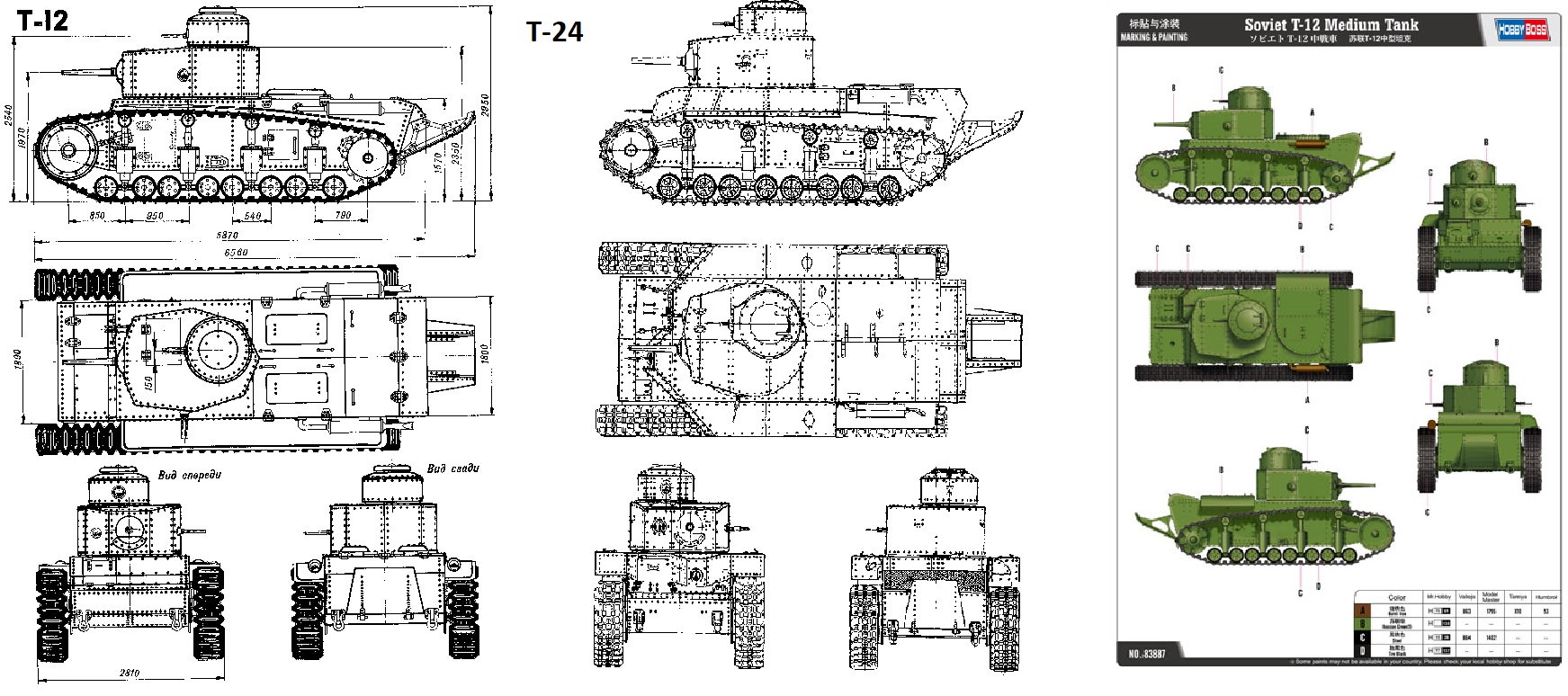
Aside from the major superstructure differences between the HobbyBoss kit and published drawings there are also discrepancies in relation to some aspects of the road wheels mounts, the number of machine guns and the rear sprocket, the rivet patterns and some other things.
To the best of my knowledge the drawings version of the T-12 is the one the designers drew up - the prototype that got built looked different for a whole number of reasons (interwar Soviet design and manufacturing being haphazard at best) and seems to be the one Hobbyboss used for their model. One of the Russian sites states that "A prototype of the T-12 tank was assembled at the KhPZ by mid-November 1929. At first, it was planned to test the vehicle at the plant by the end of the year, and then, after eliminating the shortcomings, submit the tank for general tests, which were planned to be carried out in early 1930. But it took a month and a half to prepare the T-12 prototype only for the factory runs. It should be noted that the built sample was very different from the project. Its body has become longer, the chassis and power plant have been changed."
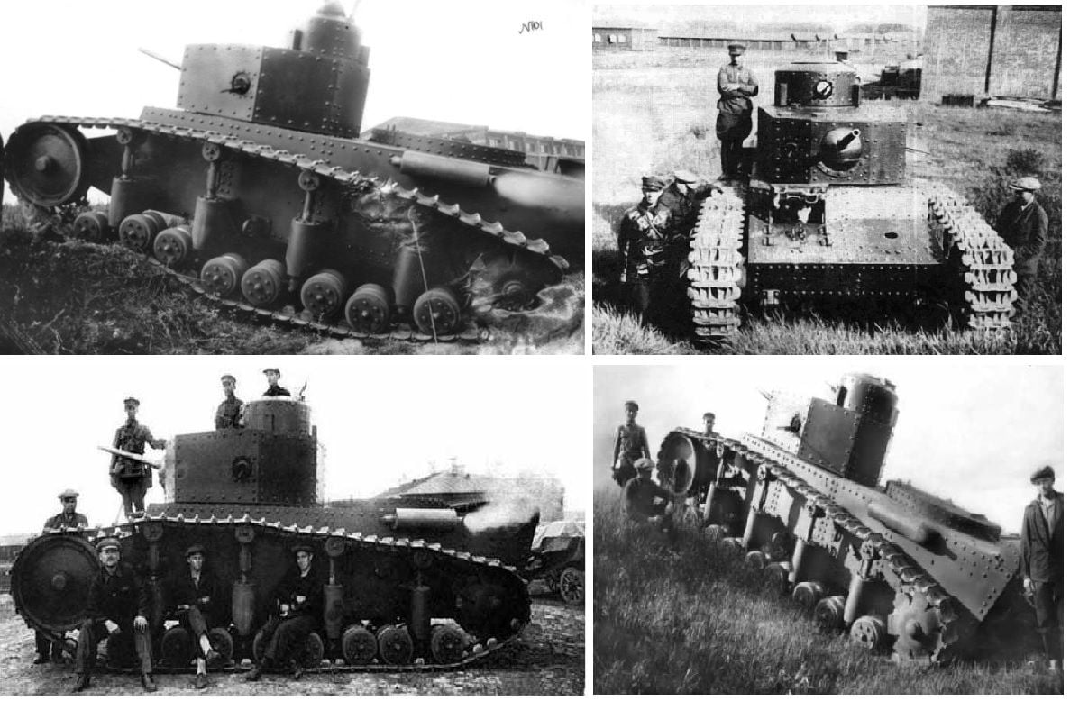
Picture 2 shows what appears to be generally accepted as the prototype that underwent testing in 1929/1930.
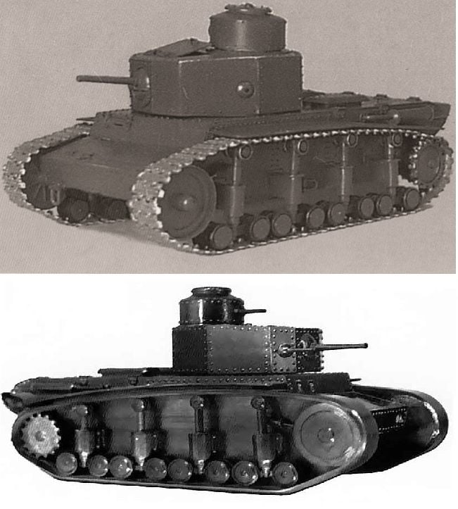
Whats even more annoying is that there are some pictures of a tank that looks very like the designers actual plans. One of them is a wooden model from the time, the other is a typical interwar "representation" of their design and the third is a grainy shot of what appears to be a prototype following the designers original plans.
Picture 3 is the wooden model and the graphic.
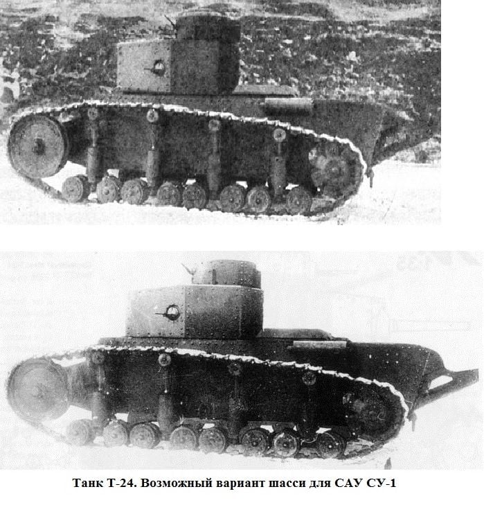
Picture 4 shows what appears to be an actual photo of the designers version of the T-12. Whats problematic is that the photo is sometimes labelled as a T-24, as in the bottom picture. Which it clearly isnt. The T-24 turret has a rounded back and the T-24 tracks did not reach as far up the hull as the T-12 tracks. So whatever that photo is of, it isn't a T-24 and it more resembles the designers T-12 (the track layout being a giveaway).
But enough....
For the purposes of my model...I'm sticking with the designers plans for the T-12. I dont like the Hobbyboss version even if it was the one that eventually got built and I have a decent print of the designers version to work from.
Im using 1.2 mm sheet steel, brass where necessary and aluminium if needed. I had an old set of cheap Tiger gearboxes and I'm hoping they fit. I have a set of Pz III plastic tracks and a sprocket which I will use too. If it comes together I will get metal tracks just for completeness. Silver solder and nuts a bolts for the fixings.
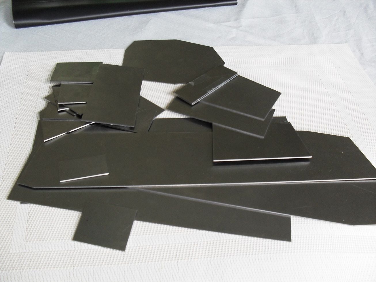
All the pieces were marked out on one large 1.2 mm sheet and cut out with a jigsaw. These were then filed to shape and any cutouts or whatever made.
I normally use a cheapo drill but the bearings are shot so I needed a new drill. Especially as there are a lot of holes on this model. So I bought a Proxxon TBM 15, a cheap compund table and really cheap rotary table from India. This will have to suffice.
For making the suspension mounts I needed some fairly thick brass which I couldnt buy. So I bought a couple of bars of 6mm thickness and simply soldered them together to get a thick bar. Then I used some 12mm diameter brass bar stock for the round bit.
Im actually a good bit further along than it appears so I will take a few more photos today once I have tidied up a little.
P
This is a 1:16 scratch build in steel of an interwar soviet T-12. Im doing this because I ran into a brick wall on my Morser Eva and needed something quick (famous last words) and easy to distract me.
The T-12 was a medium tank designed in the late 1920s which didnt get much past the prototype, rapidly being replaced by the T-24. The Soviets had captured a bunch of British Mk V tanks that had been given to the White Army and used them in various roles until the early parts of WW II. The "Report of the Artillery Directorate of the Supplies Directorate on achievements from 1925 to 1928 Part 2: Scientific research work on improving armament (Artkom)" from 1929 indicates that the T-12 was viewed as a replacement for these Mk V tanks and would be employed in a "breakthrough" and "manouver" role. 30 tanks were approved in the tank program for 1929/1930. One tank was trialled in late 1929 and early 1930 and by the following year there is no further mention of the T-12 with all emphasis having shifted to the T-24 which retains much of the design characteristics of the T-12 indicating that it must have performed very badly during the trials of 1929.
I wanted to build one as it has a seriously nifty suspension system, PzIII tracks should do a passable job of working and it has a whole load of rivets which I think look sweet.Plus you don't see too many of them and I have a fondness for paper panzers. Especially ones which have features that can be traced through to designs used even until the end of WW II.
There seems to be some confusion as to what the T-12 looked like exactly - primarily it seems to be confused with the T-24 a lot (with which it shares many features).
Picture 1 below shows the Hobby Boss T-12 kit which may be the only one available. But comparing this to "technical" drawings from Russian enthusiast sites...it obviously is not the same T-12 or at least the one most enthusiast sites view as a T-12. Its totally different in many respects. I thought at first that the Hobbyboss kit was actually a T-24 (Which was the version that appeared very quickly after the T-12 concept got scrapped) but it doesn't even seem to look like that either. I'm working off what I could find on https://www.tankarchives.ca/2017/03/...iet-tanks.html and https://tanks-encyclopedia.com/ww2/s...d%2025%20built.
Aside from the major superstructure differences between the HobbyBoss kit and published drawings there are also discrepancies in relation to some aspects of the road wheels mounts, the number of machine guns and the rear sprocket, the rivet patterns and some other things.
To the best of my knowledge the drawings version of the T-12 is the one the designers drew up - the prototype that got built looked different for a whole number of reasons (interwar Soviet design and manufacturing being haphazard at best) and seems to be the one Hobbyboss used for their model. One of the Russian sites states that "A prototype of the T-12 tank was assembled at the KhPZ by mid-November 1929. At first, it was planned to test the vehicle at the plant by the end of the year, and then, after eliminating the shortcomings, submit the tank for general tests, which were planned to be carried out in early 1930. But it took a month and a half to prepare the T-12 prototype only for the factory runs. It should be noted that the built sample was very different from the project. Its body has become longer, the chassis and power plant have been changed."
Picture 2 shows what appears to be generally accepted as the prototype that underwent testing in 1929/1930.
Whats even more annoying is that there are some pictures of a tank that looks very like the designers actual plans. One of them is a wooden model from the time, the other is a typical interwar "representation" of their design and the third is a grainy shot of what appears to be a prototype following the designers original plans.
Picture 3 is the wooden model and the graphic.
Picture 4 shows what appears to be an actual photo of the designers version of the T-12. Whats problematic is that the photo is sometimes labelled as a T-24, as in the bottom picture. Which it clearly isnt. The T-24 turret has a rounded back and the T-24 tracks did not reach as far up the hull as the T-12 tracks. So whatever that photo is of, it isn't a T-24 and it more resembles the designers T-12 (the track layout being a giveaway).
But enough....
For the purposes of my model...I'm sticking with the designers plans for the T-12. I dont like the Hobbyboss version even if it was the one that eventually got built and I have a decent print of the designers version to work from.
Im using 1.2 mm sheet steel, brass where necessary and aluminium if needed. I had an old set of cheap Tiger gearboxes and I'm hoping they fit. I have a set of Pz III plastic tracks and a sprocket which I will use too. If it comes together I will get metal tracks just for completeness. Silver solder and nuts a bolts for the fixings.
All the pieces were marked out on one large 1.2 mm sheet and cut out with a jigsaw. These were then filed to shape and any cutouts or whatever made.
I normally use a cheapo drill but the bearings are shot so I needed a new drill. Especially as there are a lot of holes on this model. So I bought a Proxxon TBM 15, a cheap compund table and really cheap rotary table from India. This will have to suffice.
For making the suspension mounts I needed some fairly thick brass which I couldnt buy. So I bought a couple of bars of 6mm thickness and simply soldered them together to get a thick bar. Then I used some 12mm diameter brass bar stock for the round bit.
Im actually a good bit further along than it appears so I will take a few more photos today once I have tidied up a little.
P

The following users liked this post:
herrmill (07-31-2020)
07-30-2020, 07:41 AM
#2
Thread Starter
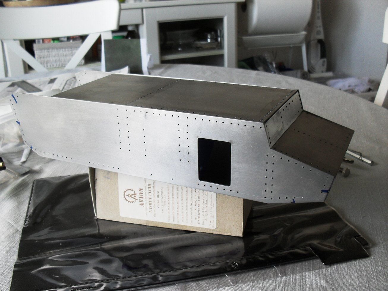
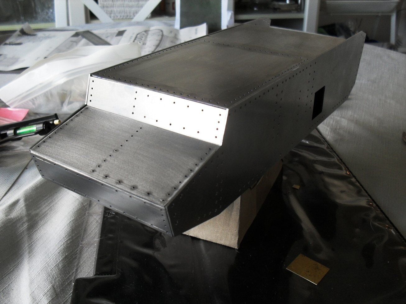
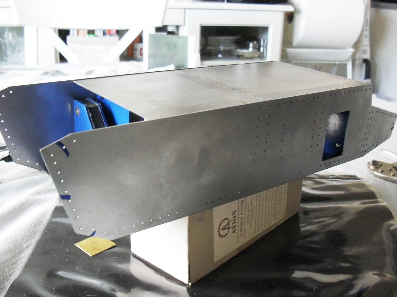
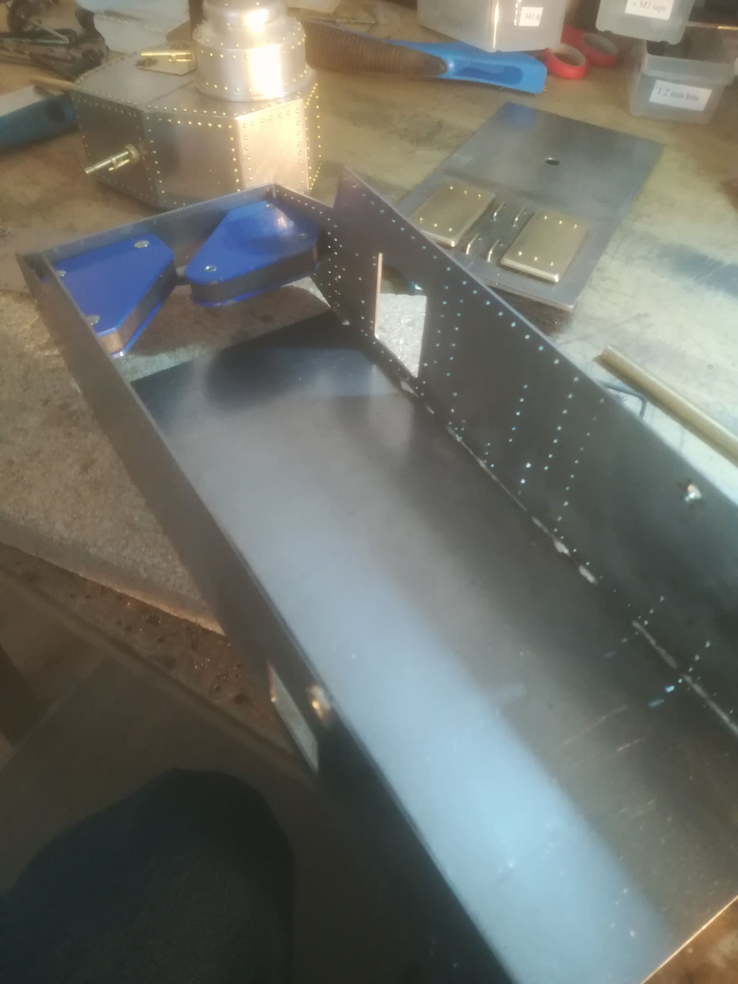
I stuck the major pieces of the hull together with magnets today to get an idea of how things are fitting in the overall scheme of things. Reasonably happy with the way they fit, nothing that cannot be fixed. behind the main upperplate is a giant hinged piece which I hope to get working. In addition to the two side hatches (the doors are made but I have to sort out hinges). The turrent is a nonogram (?) so thats going to take a bit of juggling.

The following users liked this post:
dkaniel (08-25-2020)
The following users liked this post:
herrmill (07-31-2020)
07-31-2020, 05:14 AM
#4
Thread Starter
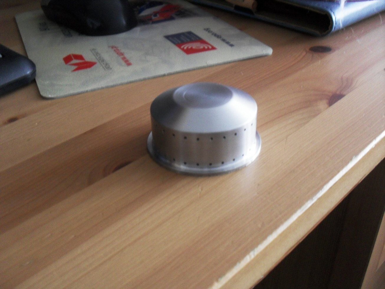
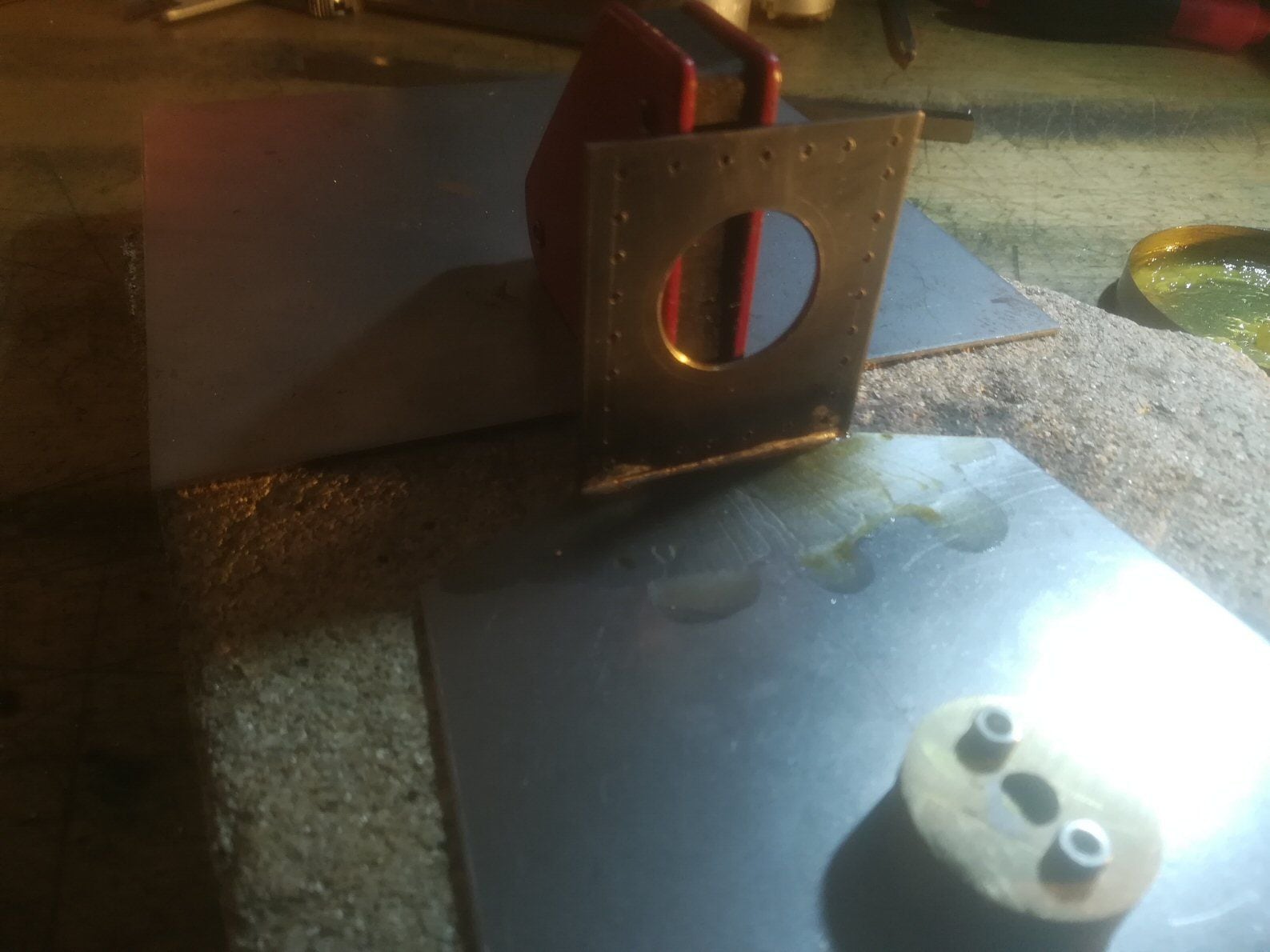
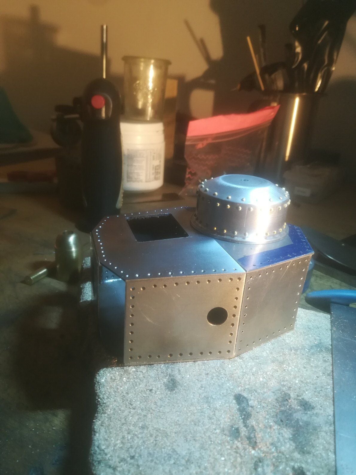
Today I started work on the cupola. Mostly because this was likely to be difficult. I had bought an aluminium petrol tank cap from a local cheap crap shop a while back - I dont know if it was for a car or a boat or what but it had the right dimensions plus or minus a millimeter or two here or there. I had to file off some features and sand it a bit but eventually it was good enough.
It needs two rings of holes around it for the rivets and it was for things like this that I purchased a cheap mini rotary table from Aliexpress for 30 euro.
I havent a chance of doing these rivet holes free hand as they need to be in line and relatively evenly spaced. I rigged up the table on the Proxxon drill and went at it. Normally I dont like drilling tiny holes in aluminium as it never goes well but this time Im using a set of carbide (I assume) PCB drill bits because I think they may work easier on 1) the round surface and 2) aluminium.

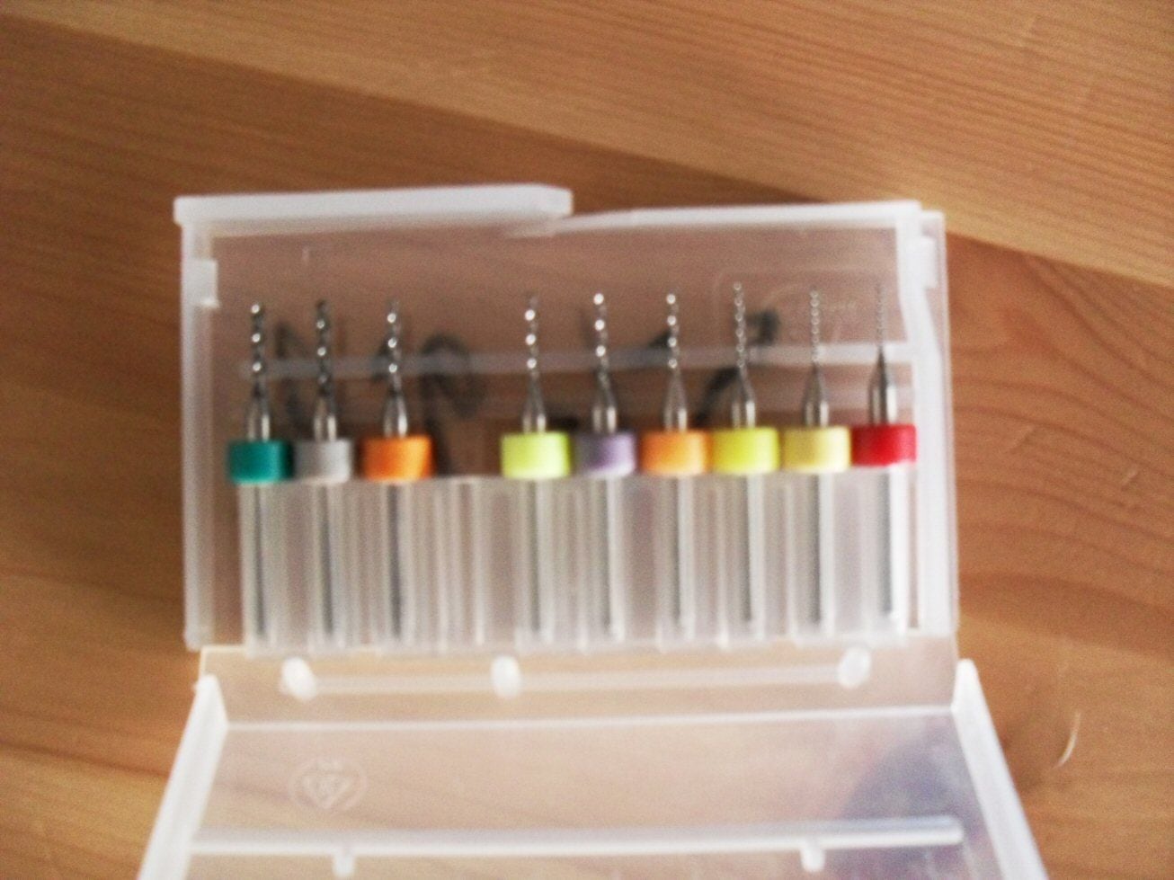
An hour later and only one broken bit, the job was done. A degree or two off here and there on some of them but I can live with that. I need to drill a big hole in the front for a machine gun mount and drill another set of holes around the sloping bit and make the top hat bit but I will get to that.
p
It needs two rings of holes around it for the rivets and it was for things like this that I purchased a cheap mini rotary table from Aliexpress for 30 euro.
I havent a chance of doing these rivet holes free hand as they need to be in line and relatively evenly spaced. I rigged up the table on the Proxxon drill and went at it. Normally I dont like drilling tiny holes in aluminium as it never goes well but this time Im using a set of carbide (I assume) PCB drill bits because I think they may work easier on 1) the round surface and 2) aluminium.
An hour later and only one broken bit, the job was done. A degree or two off here and there on some of them but I can live with that. I need to drill a big hole in the front for a machine gun mount and drill another set of holes around the sloping bit and make the top hat bit but I will get to that.
p
The following users liked this post:
herrmill (07-31-2020)
07-31-2020, 06:11 PM
#5

Nice work! Haven't done a scratch build in years - boats, that is - & do miss the fun of scrounging around for parts like that petrol cap that can be adapted for use.
Will be following this one.
Will be following this one.
08-01-2020, 07:51 AM
#7
Thread Starter
For some reason, the T-12 has tow hooks (I think) on the sides. For a tank with the usual full Soviet complement of two hitches front and two back, I do not understand why one would need one on each side. Maybe to pull the tank sideways or something? I dont know.
Irrespective.....
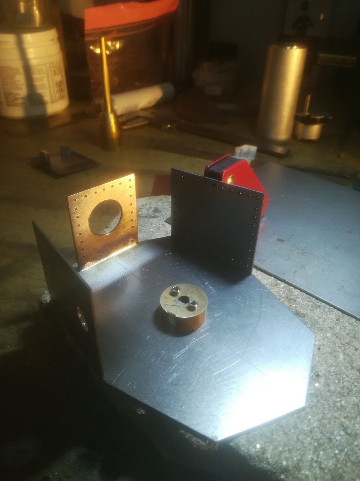
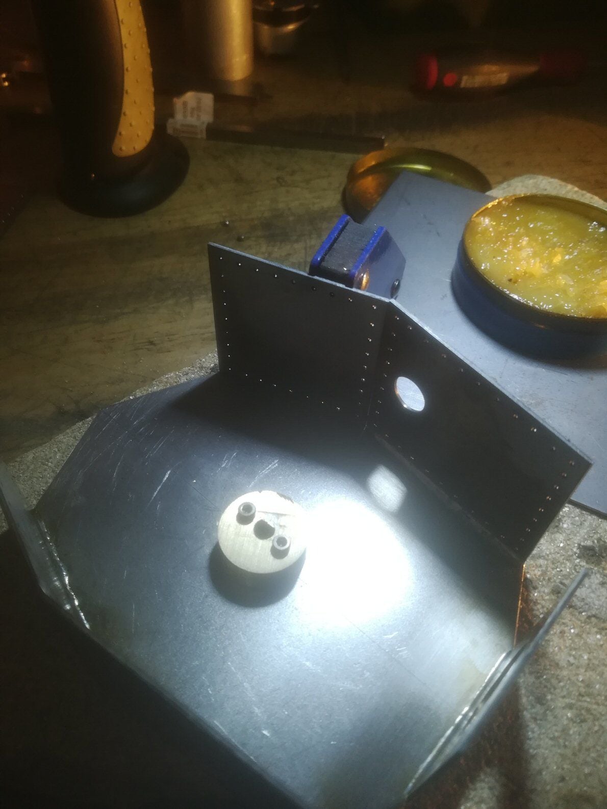
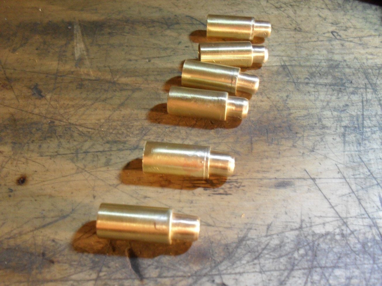
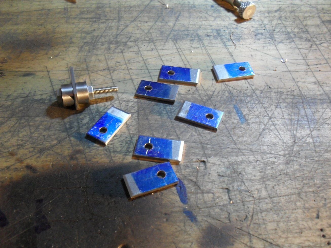
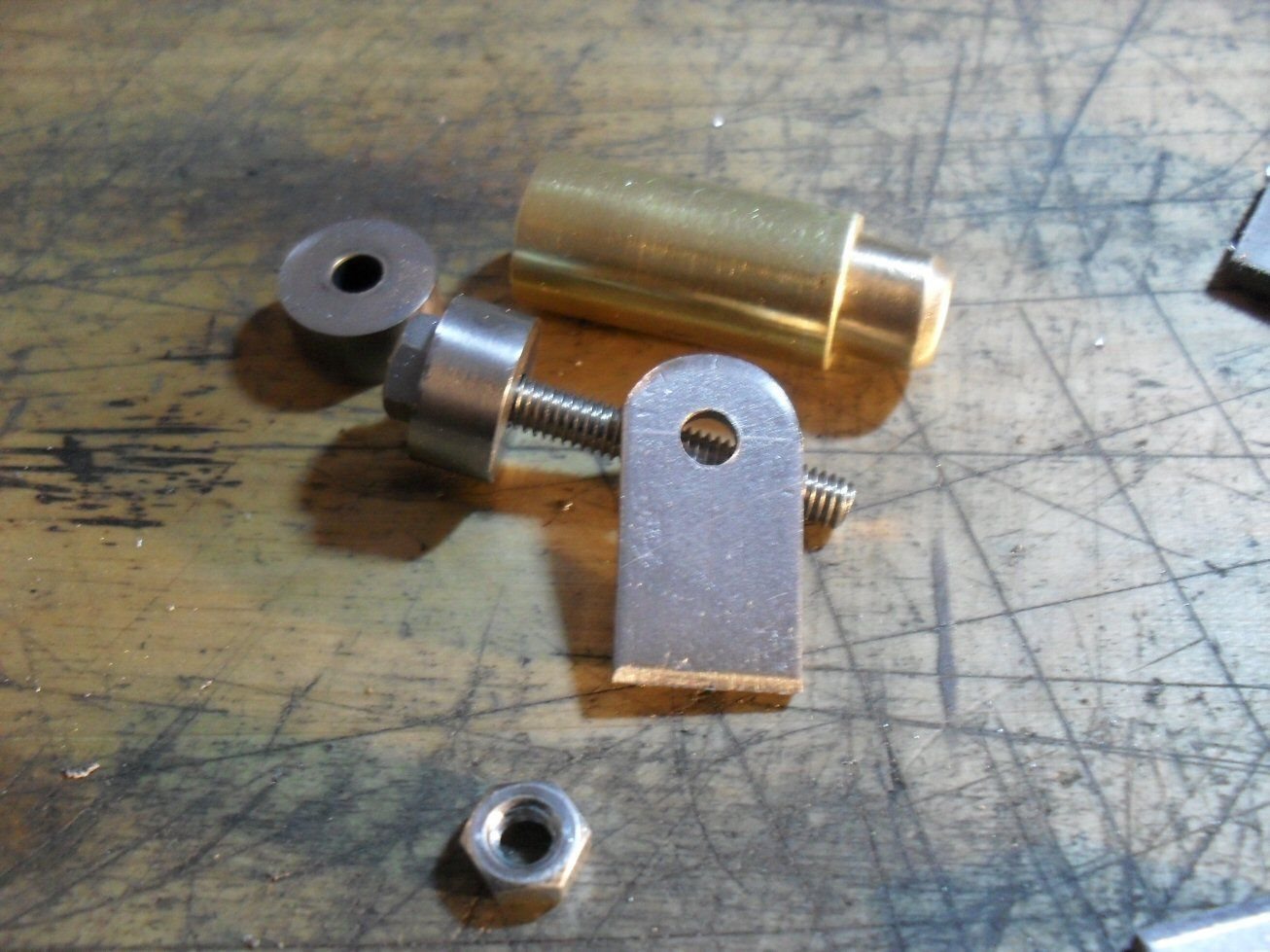
I made two little rectangles of steel and drilled 3 holes on each side of each of them and filed a little round groove doen the middle. I then took a 6mm bit of brass tube, filed it to correct length and the centre drilled it on the little drill. Then I filed a slot in each bit of brass about half way through and left it on the steel bit so that the two ends were in the groove. This was then silver soldered to the steel. using a dremel and a file, the middle bit was removed leaving two circulat bits of brass on teh steel.
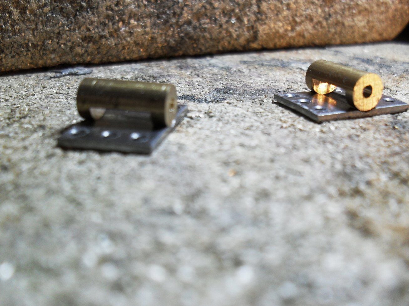
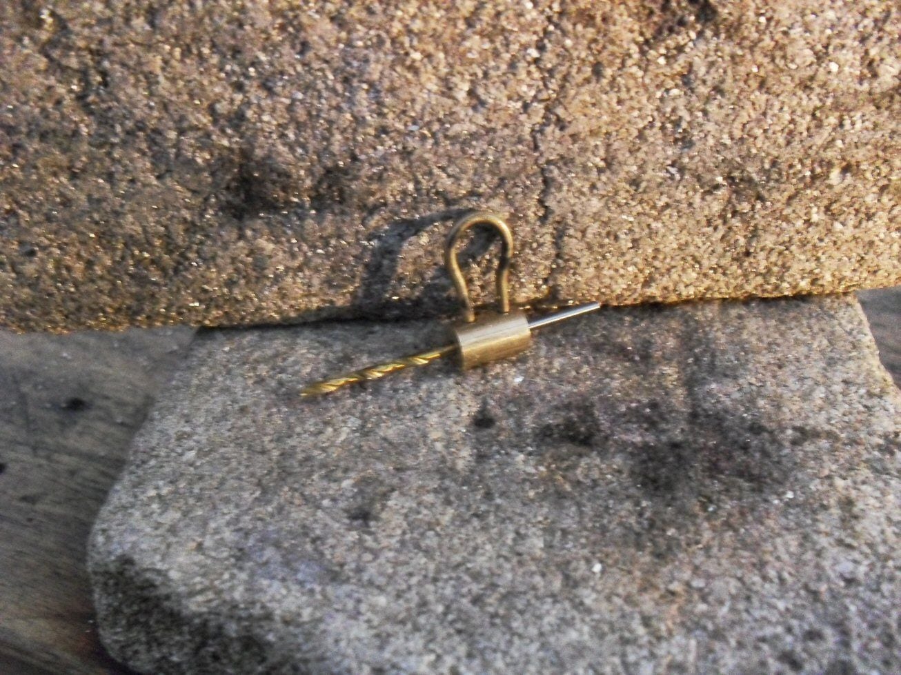
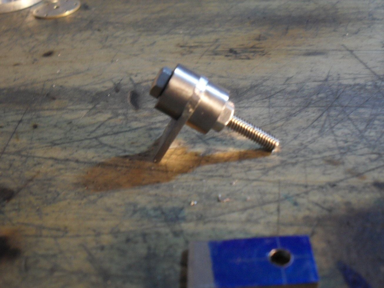
Another bit of brass was made to fit between the two rings and centre bored 1.5 mm. Two cross holes were then drilled and bent brass wired was soldered into the holes. The centre hole was then tapped to M2 and a couple of hex headed bolts and washers secured the middll bit.
It should be a simple job to then screw these to the side of the hull.
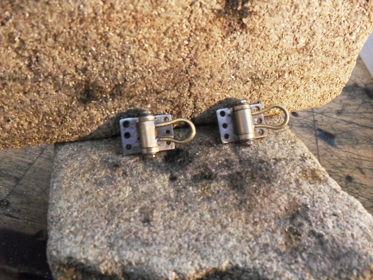
A bit rough but nothing a sanding sponge and a dremel wont tidy up.
P
Irrespective.....
I made two little rectangles of steel and drilled 3 holes on each side of each of them and filed a little round groove doen the middle. I then took a 6mm bit of brass tube, filed it to correct length and the centre drilled it on the little drill. Then I filed a slot in each bit of brass about half way through and left it on the steel bit so that the two ends were in the groove. This was then silver soldered to the steel. using a dremel and a file, the middle bit was removed leaving two circulat bits of brass on teh steel.
Another bit of brass was made to fit between the two rings and centre bored 1.5 mm. Two cross holes were then drilled and bent brass wired was soldered into the holes. The centre hole was then tapped to M2 and a couple of hex headed bolts and washers secured the middll bit.
It should be a simple job to then screw these to the side of the hull.
A bit rough but nothing a sanding sponge and a dremel wont tidy up.
P
08-25-2020, 09:06 AM
#8
Thread Starter
Hello
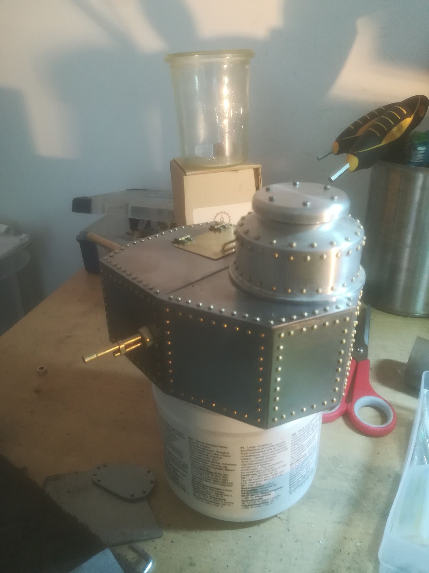
Time for an update. As of now I have the entire hull fabricatd but not stuck together, the road wheels (all 32) have been cut from 18mm dia. aluminium ( I couldnt do steel as that needs machines), all machine guns made (but not soldered together), all hatches made with hinges, main cannon made, cupola pretty much finished.
I was hoping to attack the running gear but was waiting for bras stube from ebay. Eventually an empty package arrived, the tubes obviously having punched a hole and made their escape en route. So I had to reorder and thats delayed the running gear.
So I went at the turret which I was dreading.
I use a tin heavy solder for holding such things together and either "soldering fat" (no idea what the english for that is) or one of those acid-ZnCl solutions.

I still have some panels to attach but it went not so bad. I cannot solder on the top panels as the machine guns have to be attached first but test fitting them was reasonable. There will be some filler necessary and a bit of fine tuning but otherwise.....not so bad.
P
Time for an update. As of now I have the entire hull fabricatd but not stuck together, the road wheels (all 32) have been cut from 18mm dia. aluminium ( I couldnt do steel as that needs machines), all machine guns made (but not soldered together), all hatches made with hinges, main cannon made, cupola pretty much finished.
I was hoping to attack the running gear but was waiting for bras stube from ebay. Eventually an empty package arrived, the tubes obviously having punched a hole and made their escape en route. So I had to reorder and thats delayed the running gear.
So I went at the turret which I was dreading.
I use a tin heavy solder for holding such things together and either "soldering fat" (no idea what the english for that is) or one of those acid-ZnCl solutions.
I still have some panels to attach but it went not so bad. I cannot solder on the top panels as the machine guns have to be attached first but test fitting them was reasonable. There will be some filler necessary and a bit of fine tuning but otherwise.....not so bad.
P
08-25-2020, 09:50 AM
#9
OMG! I enjoyed drooling over these images so much I just had to grab a beer! And such a sweet piece of armor to build too.
Please, don't leave us hanging.
Please, don't leave us hanging.
08-26-2020, 08:39 AM
#10
Thread Starter
Hello
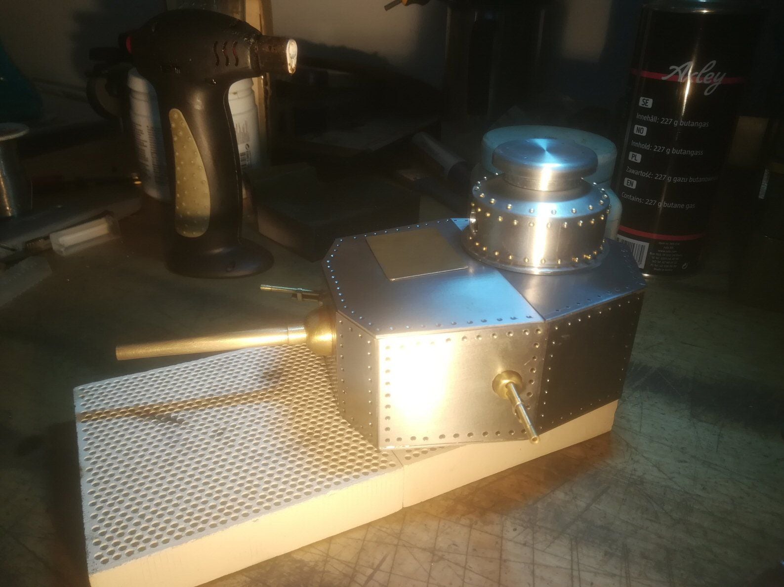
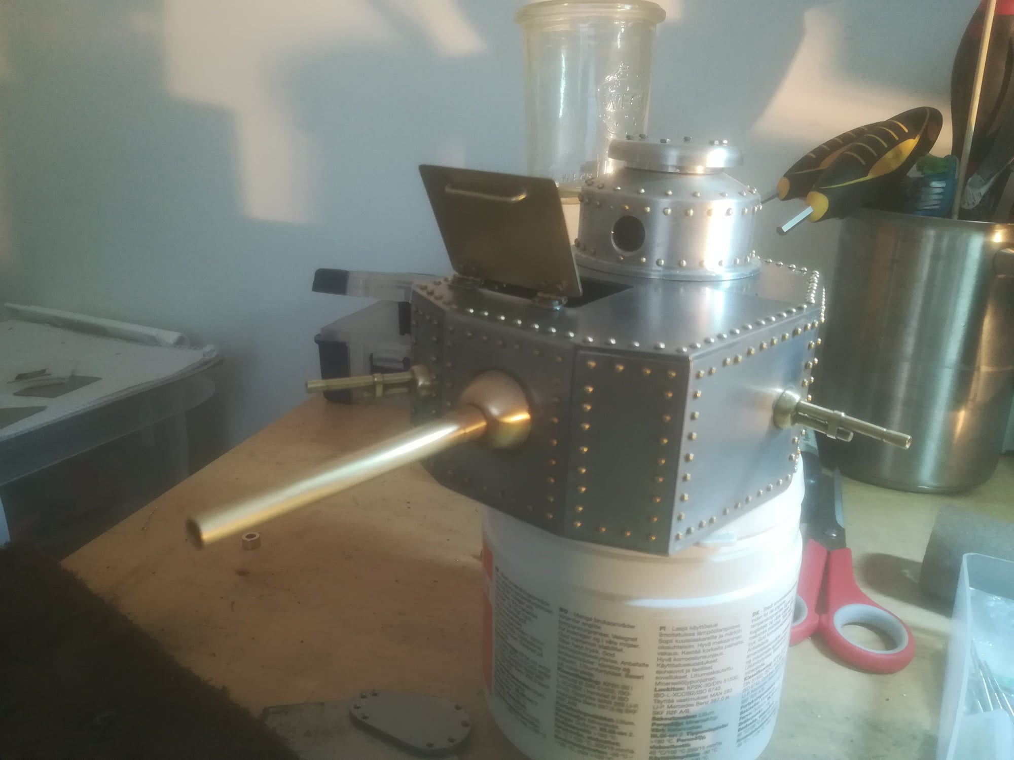
Added a cannon and two machine guns to the turret as well as the top hat on the cupola. A machine gun should go in this cupola but I have to assume that the cupola could rotate independent of the turret otherwise how does the hatch open?
The hatch needs finishing and there is a whole passle of filling and sanding to do before I can sign off on the turret. Will be glad to see the back of that.
P
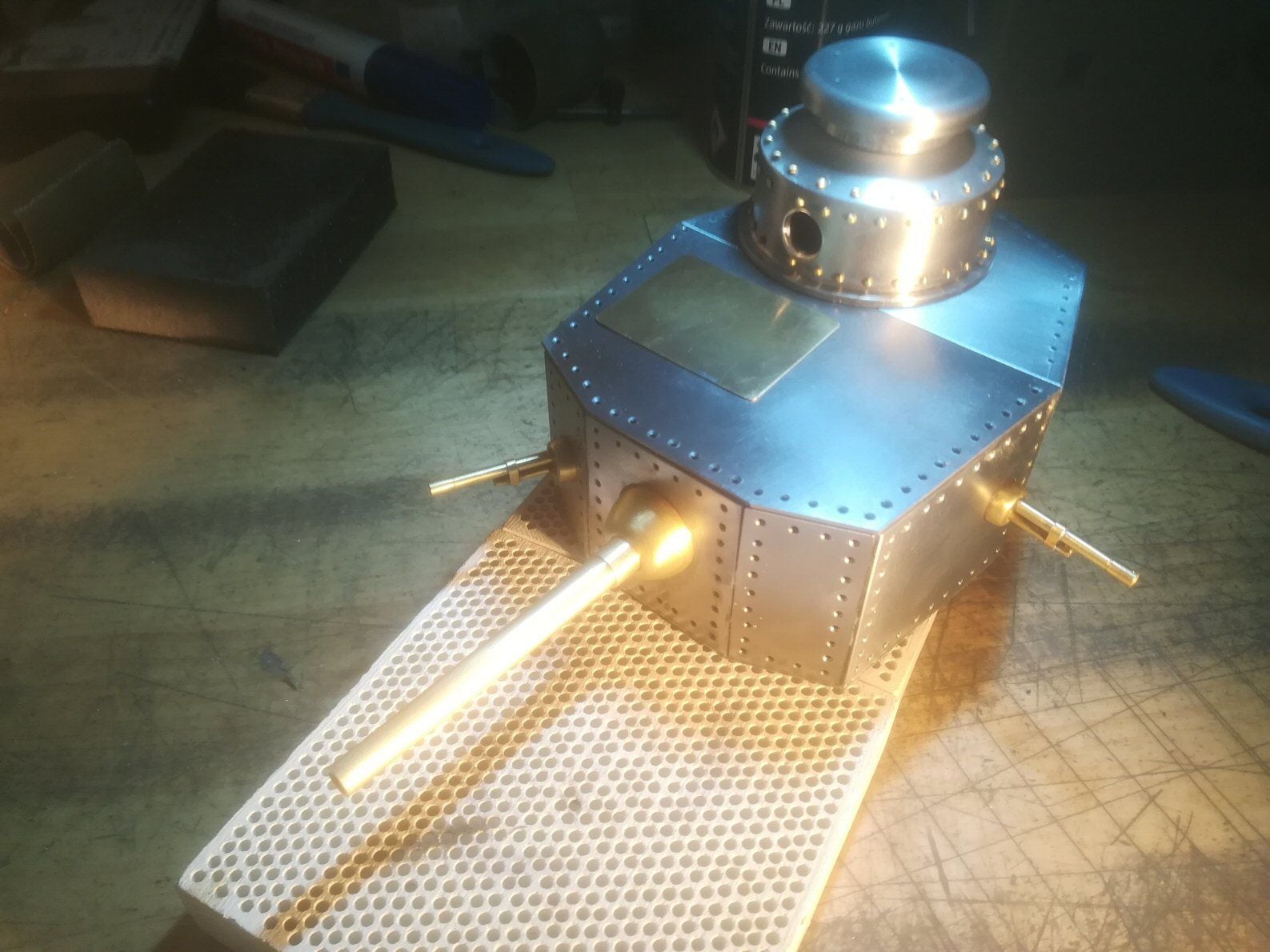
08-26-2020, 02:49 PM
#11
Really nice turret and metal work. It takes a lot of patience to drill all those holes by hand. Really cool work! One nice thing about steel it can be soldered.
Keep her going!
Bob
Keep her going!
Bob
08-29-2020, 03:22 AM
#12
Thread Starter
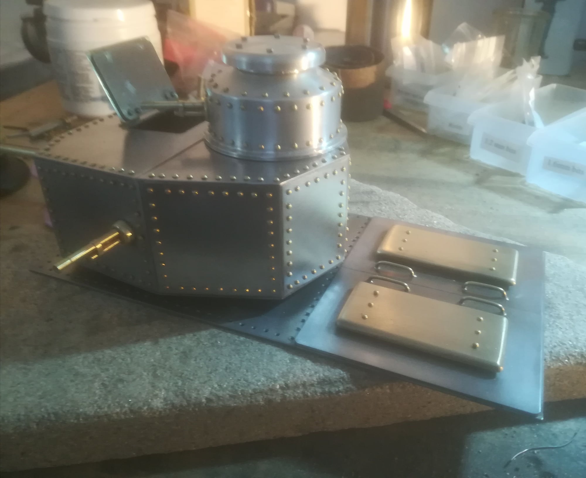
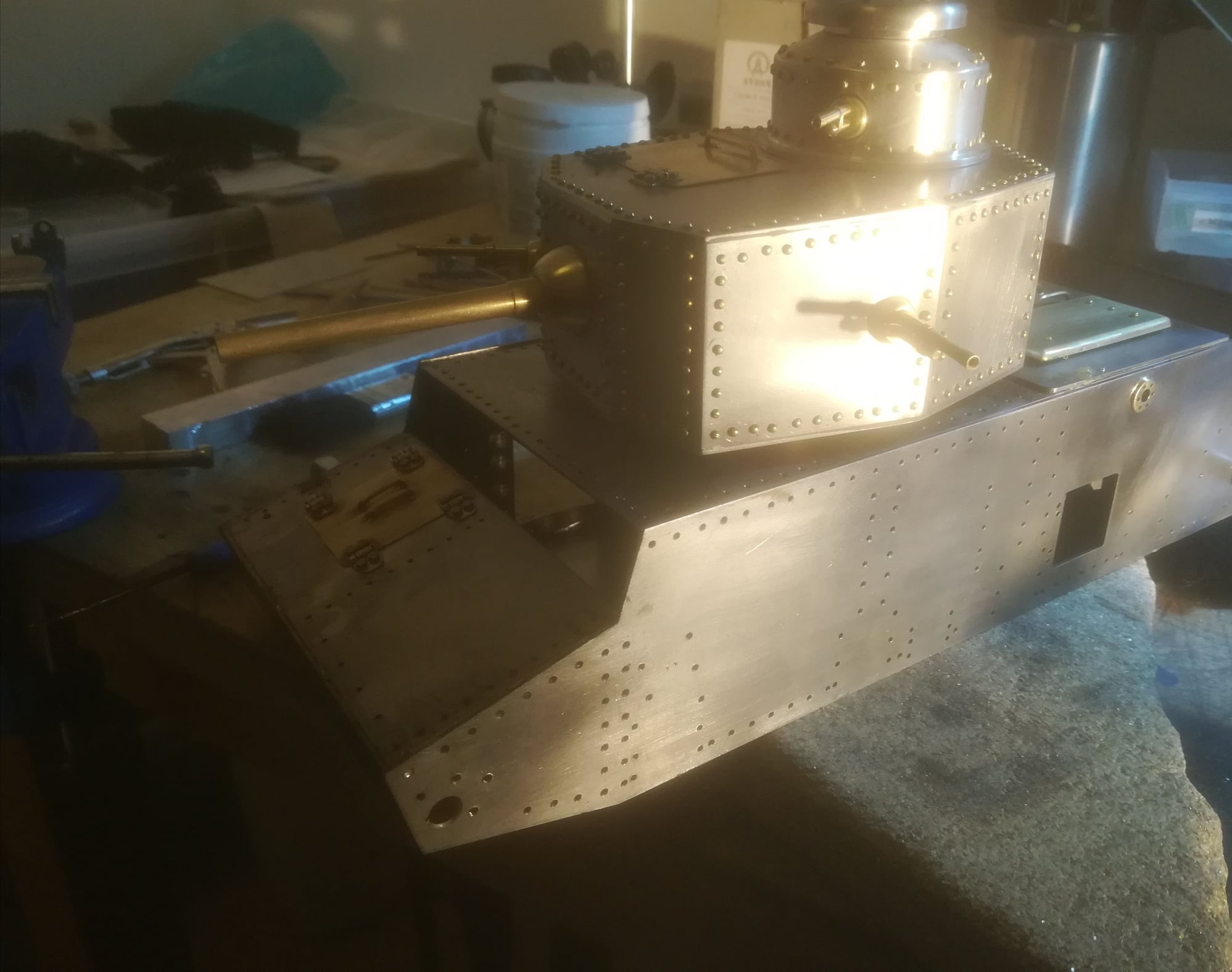
Finally made some real headway on the turret. Still have to finalise the cupola and there is some chin armor to go on under the cannon.
Glad to be finished banging in rivets though. Bit mor filler needed here and there too.
p
08-29-2020, 11:20 AM
#14
THAT must be something to see up close!
08-29-2020, 03:59 PM
#15
Riveting! 
08-31-2020, 09:34 AM
#16
Thread Starter
Hello
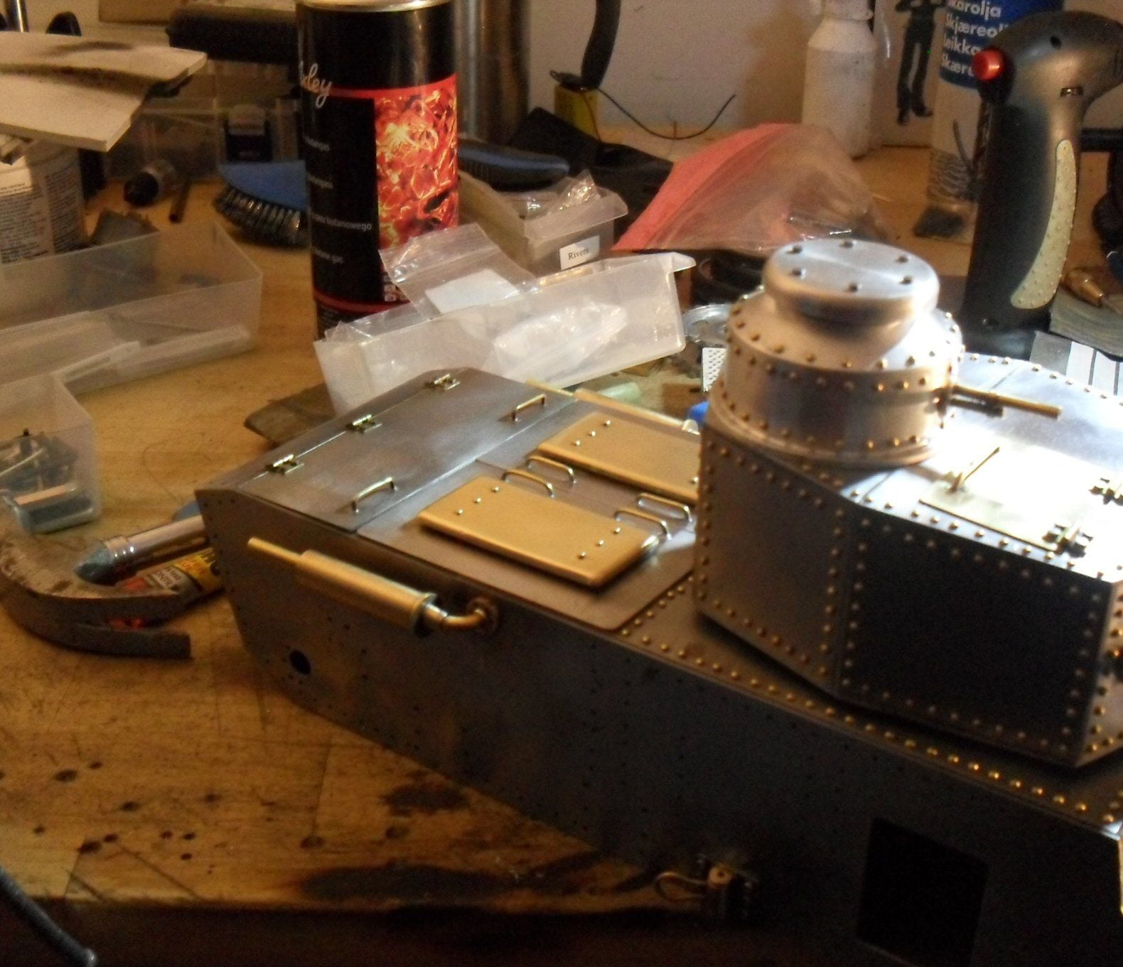
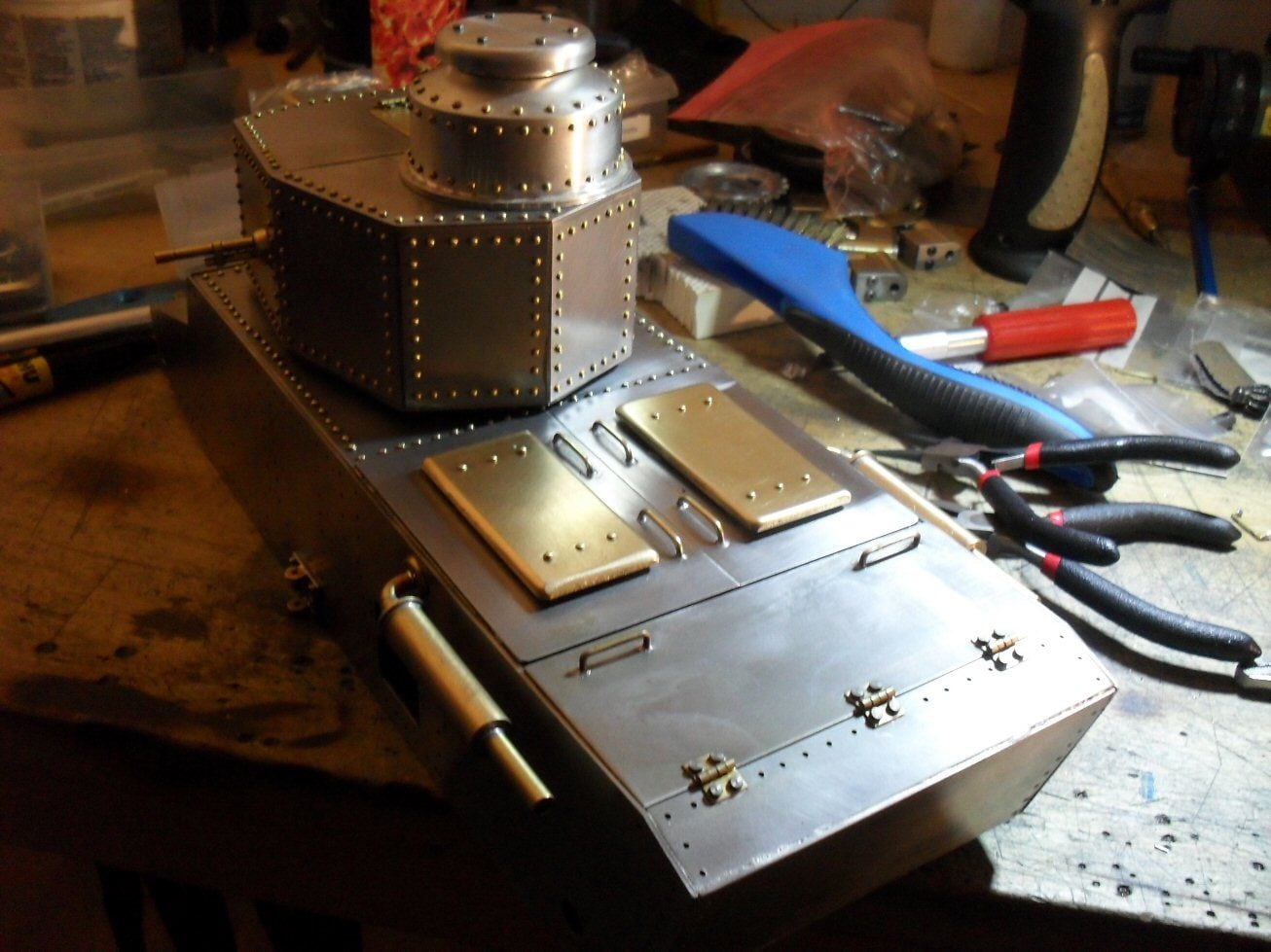
not much free time today so I roughed out the engine deck. It actually ended up nearly finished apart from a clean up and sanding so I lycked out there really.
p
not much free time today so I roughed out the engine deck. It actually ended up nearly finished apart from a clean up and sanding so I lycked out there really.
p
09-03-2020, 02:56 PM
#17
Looks great so far!!!
09-04-2020, 11:26 AM
#18
Thread Starter
A big moment in any tanks life........putting the hull together.
This was a bit of a faff as there were lots of bits....exhausts, hatches, drive bits.....that had to go together in advance.
Im lucky in that the gear boxs seem to just about fit. There are one or two panels that need tweaking before they are fitting correctly.
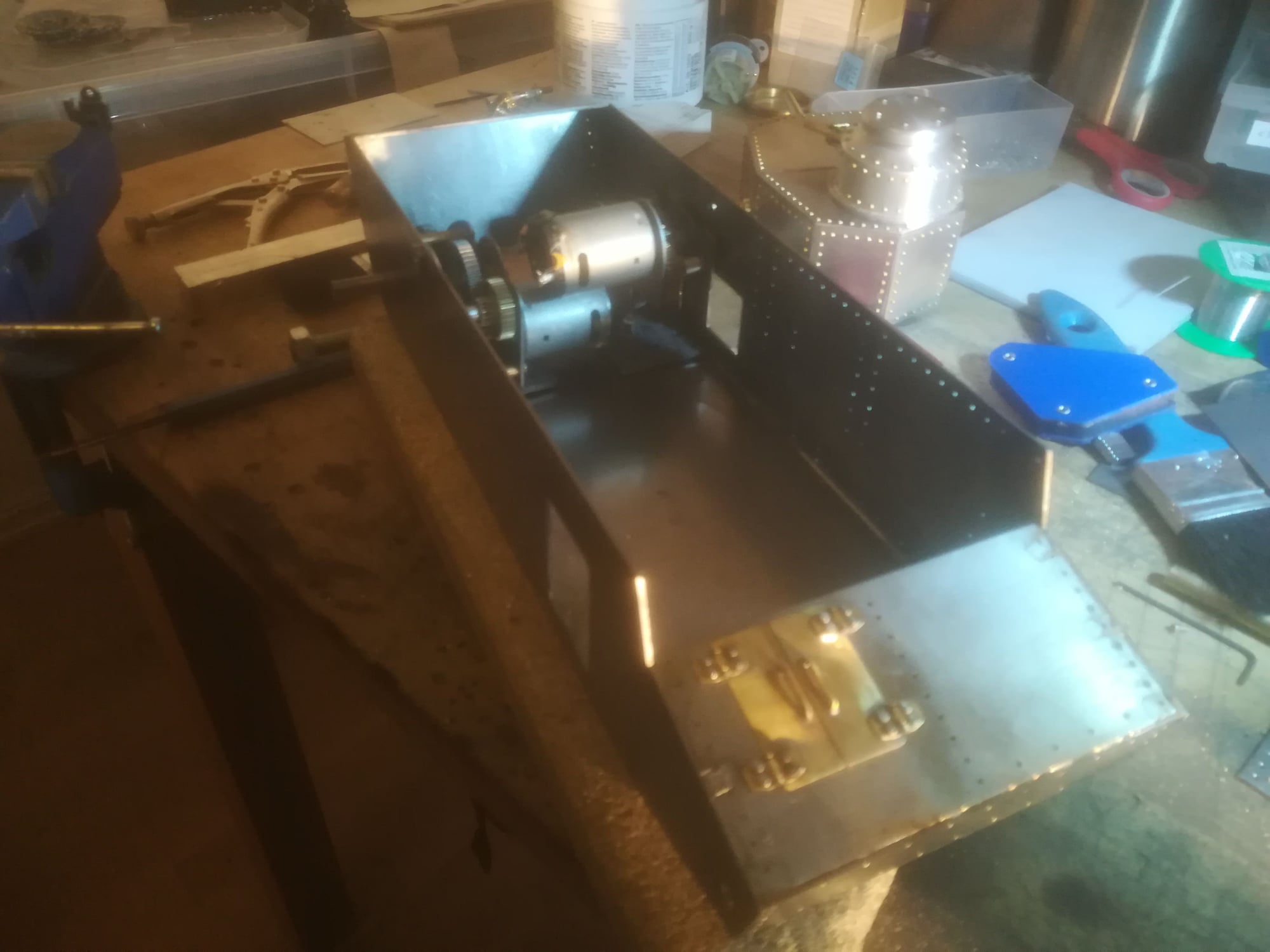
Where I have not been lucky is in getting hold of the brass I need for one bit of the running gear. I guess I'll just proceed with the bits i can do and try and be patient.
p
This was a bit of a faff as there were lots of bits....exhausts, hatches, drive bits.....that had to go together in advance.
Im lucky in that the gear boxs seem to just about fit. There are one or two panels that need tweaking before they are fitting correctly.
Where I have not been lucky is in getting hold of the brass I need for one bit of the running gear. I guess I'll just proceed with the bits i can do and try and be patient.
p
09-10-2020, 02:24 PM
#19
Wow, the metal work is fantastic!!!
09-11-2020, 08:04 AM
#20
Thread Starter
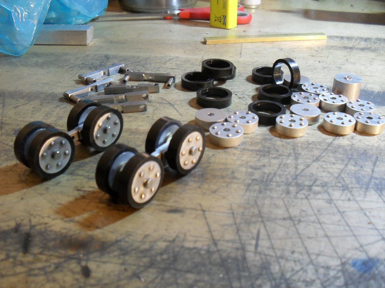
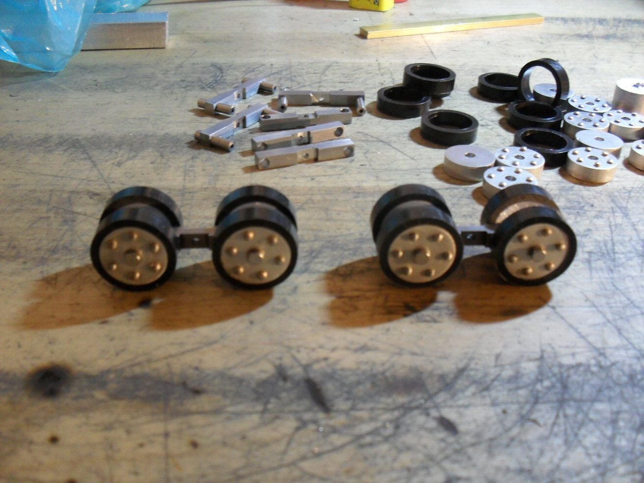
Finally went at the running gear. Starting from the bottom up. The wheels are 18mm diameter aluminium bar as 18mm steel is beyond my capacity to work with.
Cut slices off the bar, centre drilled the slices and filed/sanded them to shape. The studs are "brass" nails for picture frames from Clas Ohlson which turned out to be brass coloured steel.
The "tires" were an 18mm ID delrin pipe. Slices were cut with a hot wire and then sanded down. The metal bits were then pressed into them. I know some dont like plastic tires....but Im not making rubber ones. A bit of sanding and taking the sharp edges off them and they should be fine.
The cross member was 5mm x 5mm mild steel. Lengths were cut and all brought to the same length. Three holes were then drilled. The centre bit had to be brought carefully down to 3 mm thick with a small file. This really tested me but I have beem watching clickspring videos on youtube and his filing tutorial and tips is really first class!
The two end ones are 4 mm and a short bit of 4mm silver steel was supposed to form the axles. Cutting these was no problem but centre drilling them was a nightmare and only 50% cameout decent. The bad ones will be on the back side of the roadwheels so shouldnt be visible.
Then these had to be tapped to M2 which did not go well. I only got 4 done before I broke my last tap so the rest have to wait til I get some more.
P
09-16-2020, 04:29 AM
#21
Road wheels look great!!!
09-16-2020, 08:15 AM
#22
Thread Starter
Seeing as I am tapless, I decided to plough on with the rest of the running gear. In this case, the suspension. The first part of this was the housing for the spring and the first part of the road wheel mount.
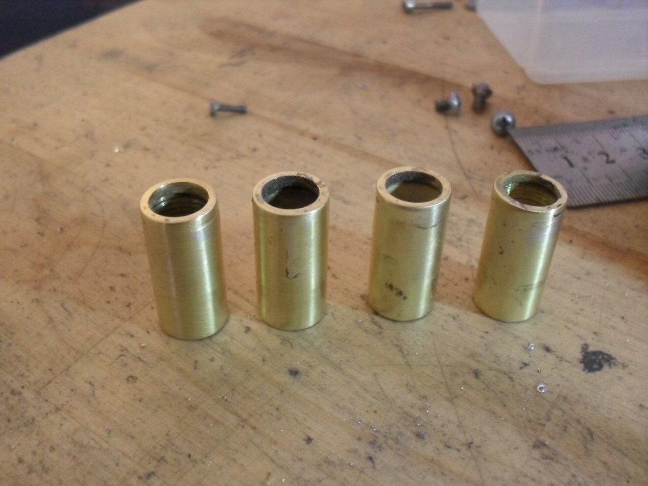
To make the spring housing, I took some lengths of 12 mm OD, 10 mm ID brass tubing. I then centre bored some 12 mm dia. brass rod with a 9 mm hole and cut some slices of it. These were then silver soldered to the bottom of the 12 mm tubes giving me a 0.5 mm lip all round the bottom of the tubes.
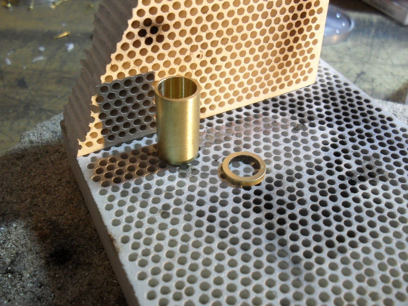
I then took some 15mm lengths of 9mm brass stock and bored a 4 mm hole down the centre. The about 8 mm of 4 mm brass bar was stuffed in the hole so about 5 mm protruded out the end. This was then silver soldered in. Then a 10 mm brass bar was centre drilled 4 mm and some slices cut off. These slices were then silver soldered to the 4 mm stub sticking out the top.
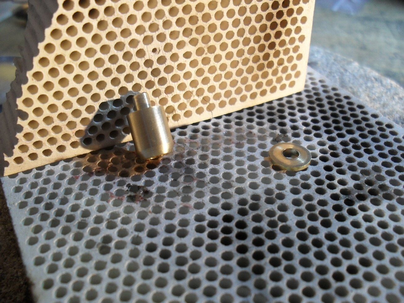
This piece was then slid into the tube. The ring on the top of the short piece catches the rim on the tube and stops it falling out. The little nub on the top of the short piece will locate the base of the spring in the tube.
The top of the tube will be capped with a 2 mm piece of steel which also supports the shaft that the return rollers are mounted on. It counld not be teh same thickness steel as the rest and there will be substantial spring pressure oon it. To make this piece I needed a rectangular piece with a 12mm diameter curve on one end to match the 12 mm tube.
To do this I used my favourite tool I possess - a filing button. These are just pieces of various diameter silver steel with holes of various diameters in them . A friend made these on his lathe for me some years ago and I suppose I have about 30 in a numberof different ID and OD's.
They were then hardened and not tempered. No file can scratch them. They are essentially free, extremely handy and if you dont have machinery,.....very handy.
I just clamped two around the centre point of teh curve I needed and with a few strokes of teh file...a perfect curve. If I was to set that up in a rotary table and a mill, it would take 10 or fifteen minutes. It literally took 3 minutes using the buttons.
Cannot recommend them enough.
These are the top plates for the spring tubes. One of them clamped in the filing buttons.

A couple of strokes of a file.......
3 minutes later
p
To make the spring housing, I took some lengths of 12 mm OD, 10 mm ID brass tubing. I then centre bored some 12 mm dia. brass rod with a 9 mm hole and cut some slices of it. These were then silver soldered to the bottom of the 12 mm tubes giving me a 0.5 mm lip all round the bottom of the tubes.
I then took some 15mm lengths of 9mm brass stock and bored a 4 mm hole down the centre. The about 8 mm of 4 mm brass bar was stuffed in the hole so about 5 mm protruded out the end. This was then silver soldered in. Then a 10 mm brass bar was centre drilled 4 mm and some slices cut off. These slices were then silver soldered to the 4 mm stub sticking out the top.
This piece was then slid into the tube. The ring on the top of the short piece catches the rim on the tube and stops it falling out. The little nub on the top of the short piece will locate the base of the spring in the tube.
The top of the tube will be capped with a 2 mm piece of steel which also supports the shaft that the return rollers are mounted on. It counld not be teh same thickness steel as the rest and there will be substantial spring pressure oon it. To make this piece I needed a rectangular piece with a 12mm diameter curve on one end to match the 12 mm tube.
To do this I used my favourite tool I possess - a filing button. These are just pieces of various diameter silver steel with holes of various diameters in them . A friend made these on his lathe for me some years ago and I suppose I have about 30 in a numberof different ID and OD's.
They were then hardened and not tempered. No file can scratch them. They are essentially free, extremely handy and if you dont have machinery,.....very handy.
I just clamped two around the centre point of teh curve I needed and with a few strokes of teh file...a perfect curve. If I was to set that up in a rotary table and a mill, it would take 10 or fifteen minutes. It literally took 3 minutes using the buttons.
Cannot recommend them enough.
These are the top plates for the spring tubes. One of them clamped in the filing buttons.
A couple of strokes of a file.......
3 minutes later
p
09-20-2020, 09:39 AM
#23
Thread Starter
Today I finished putting the spring housings for the suspension together. The top steel plates then will have a 4 mm shaft soldered to the top. This holds the return rollers. Im holding off on this slightly as I need the lengths of those shafts to be such that the tracks have the correct proifle. So I have to wait a bit until the idlers and sprockets have been test fitted with teh road wheels in place.
Th etop plates also need 6 bolts around the base of the shaft but that I have to think about. These entire assemblies are then soldered to a steel plate which is then bolted to the hull. The plates are made and I just h ave to do some test fitting to make sure teh assemblies are entirely vertical.
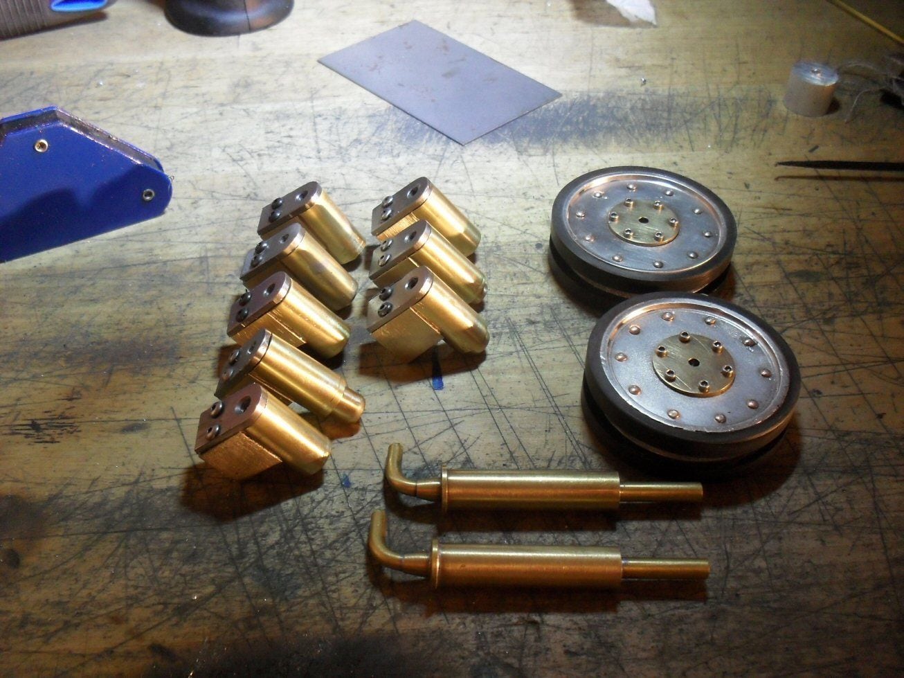
I made the idlers yesterday from a number of aluminium disks and some brass dog name tags. The tires are just rings off a pipe. Dont know what its made of.
The exhausts are made as well, simply fashioned from brass bar stock.If my M2 taps would arrive, I would be on the last lap I reckon.
P
P
Th etop plates also need 6 bolts around the base of the shaft but that I have to think about. These entire assemblies are then soldered to a steel plate which is then bolted to the hull. The plates are made and I just h ave to do some test fitting to make sure teh assemblies are entirely vertical.
I made the idlers yesterday from a number of aluminium disks and some brass dog name tags. The tires are just rings off a pipe. Dont know what its made of.
The exhausts are made as well, simply fashioned from brass bar stock.If my M2 taps would arrive, I would be on the last lap I reckon.
P
P
09-22-2020, 09:22 AM
#24
Thread Starter
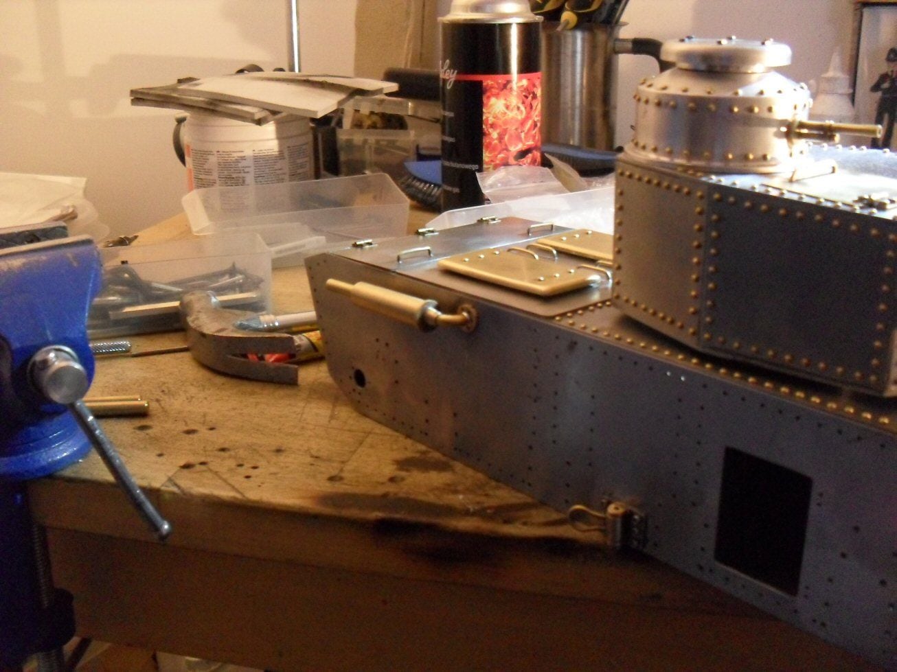
Finally finished off the engine deck today. Theres a whole lot of rivets to go in but Im keeping that for a night when there is nothing on the TV. Exhausts mounted and its just occurred to me that the tracks have to go under them ....so I really have to be careful with the return rollers.
Next thing is the gearboxes...I cocked up royally with those and got some measurements wrong so there is going to have to be a whole lot of shoehorning and messing about.
P
Next thing is the gearboxes...I cocked up royally with those and got some measurements wrong so there is going to have to be a whole lot of shoehorning and messing about.
P
The following users liked this post:
herrmill (07-03-2021)

