


Hetzer: Origins (?)
 12-10-2020, 03:00 AM
#26

Thread Starter
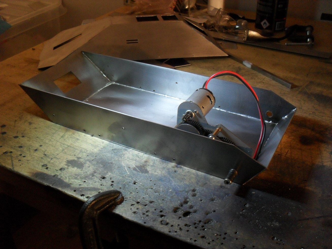
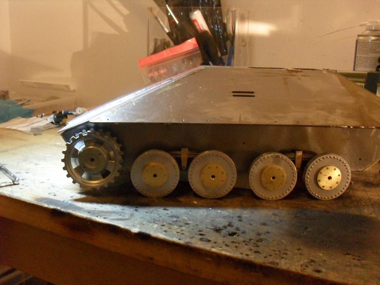
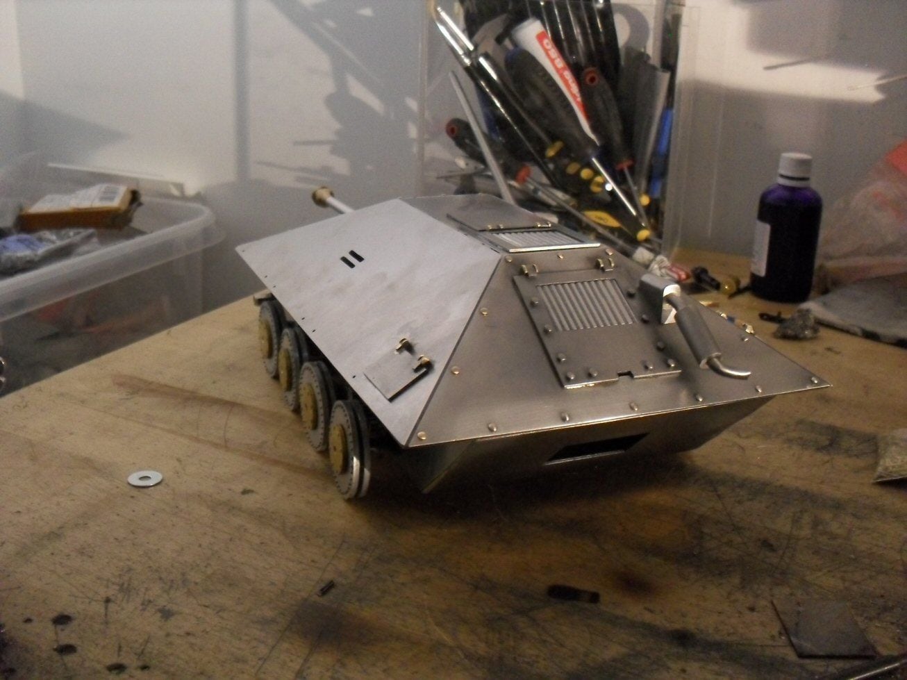
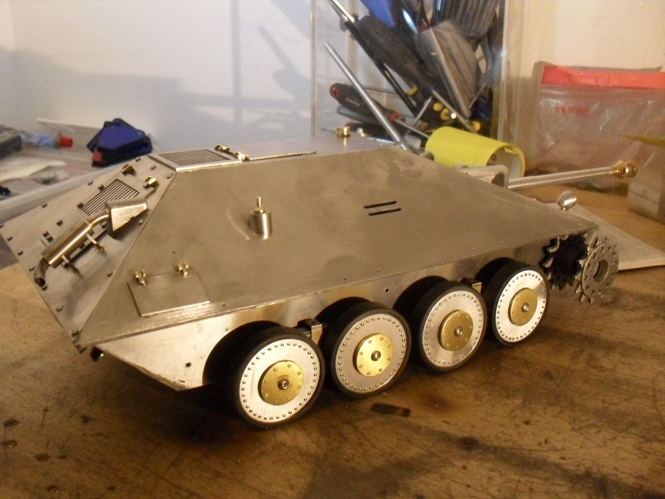
For a numberof reasons, I had to assemble the bottom of the hull. I don't like doing this before the running gear is ready but in this case I had to. I left some indicator holes of where things have to go so they should help.
The bottom was easy to assemble with no issues at all.
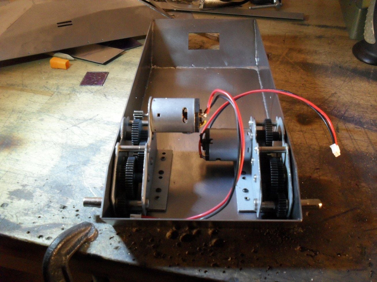
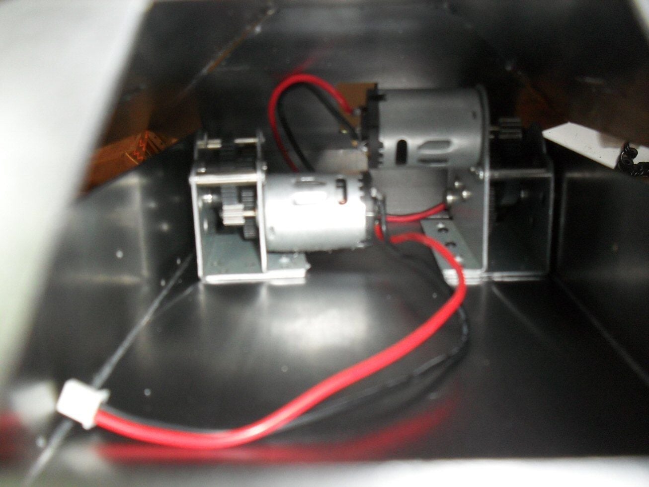
The biggest potential problem was that the gearboxes would not fit but they do with headroom.
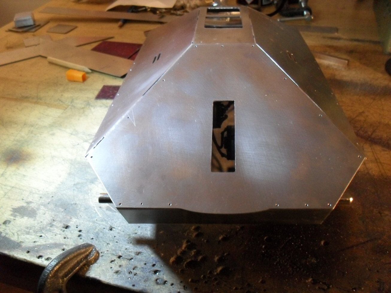
But then I got a shock when I looked around the back...... the bottom is, and I have no idea why, two millimeters too long which is producing a very unsightly gap indeed.
Short of redoing the bottom (which is a lot hassle) Im going to have to fix this somehow which won't be easy. My plan would be to solder some 3 mm thick brass along the upper rear lip of the bottom. Then file this down along the width of the hull bottom thereby shortening it.
This will also introduce a narrow vertical surface that should not be there but Im goingto have to suck it up and live with it.
The suspension is leaf spring. My plan for this is to use junior hacksaw blades - they are springy, the right width and all I should have to go is grind the teeth of and cut them to length.
p
The bottom was easy to assemble with no issues at all.
The biggest potential problem was that the gearboxes would not fit but they do with headroom.
But then I got a shock when I looked around the back...... the bottom is, and I have no idea why, two millimeters too long which is producing a very unsightly gap indeed.
Short of redoing the bottom (which is a lot hassle) Im going to have to fix this somehow which won't be easy. My plan would be to solder some 3 mm thick brass along the upper rear lip of the bottom. Then file this down along the width of the hull bottom thereby shortening it.
This will also introduce a narrow vertical surface that should not be there but Im goingto have to suck it up and live with it.
The suspension is leaf spring. My plan for this is to use junior hacksaw blades - they are springy, the right width and all I should have to go is grind the teeth of and cut them to length.
p
 12-10-2020, 08:58 AM
#27
Looks like Da Vinci's tank! Nice work! For the 2mm gap - can you still add a small extension plate to the top hull? Shouldn't be that hard to hide 2mm. 
When I scratch build I always build the tracks, wheels and lower hull first. Those are the most difficult - and the tracks <or lack of> can derail a project..
This is an interesting project, Love following your work!
Bob
When I scratch build I always build the tracks, wheels and lower hull first. Those are the most difficult - and the tracks <or lack of> can derail a project..
This is an interesting project, Love following your work!
Bob
12-10-2020, 10:45 AM
#28
Thread Starter
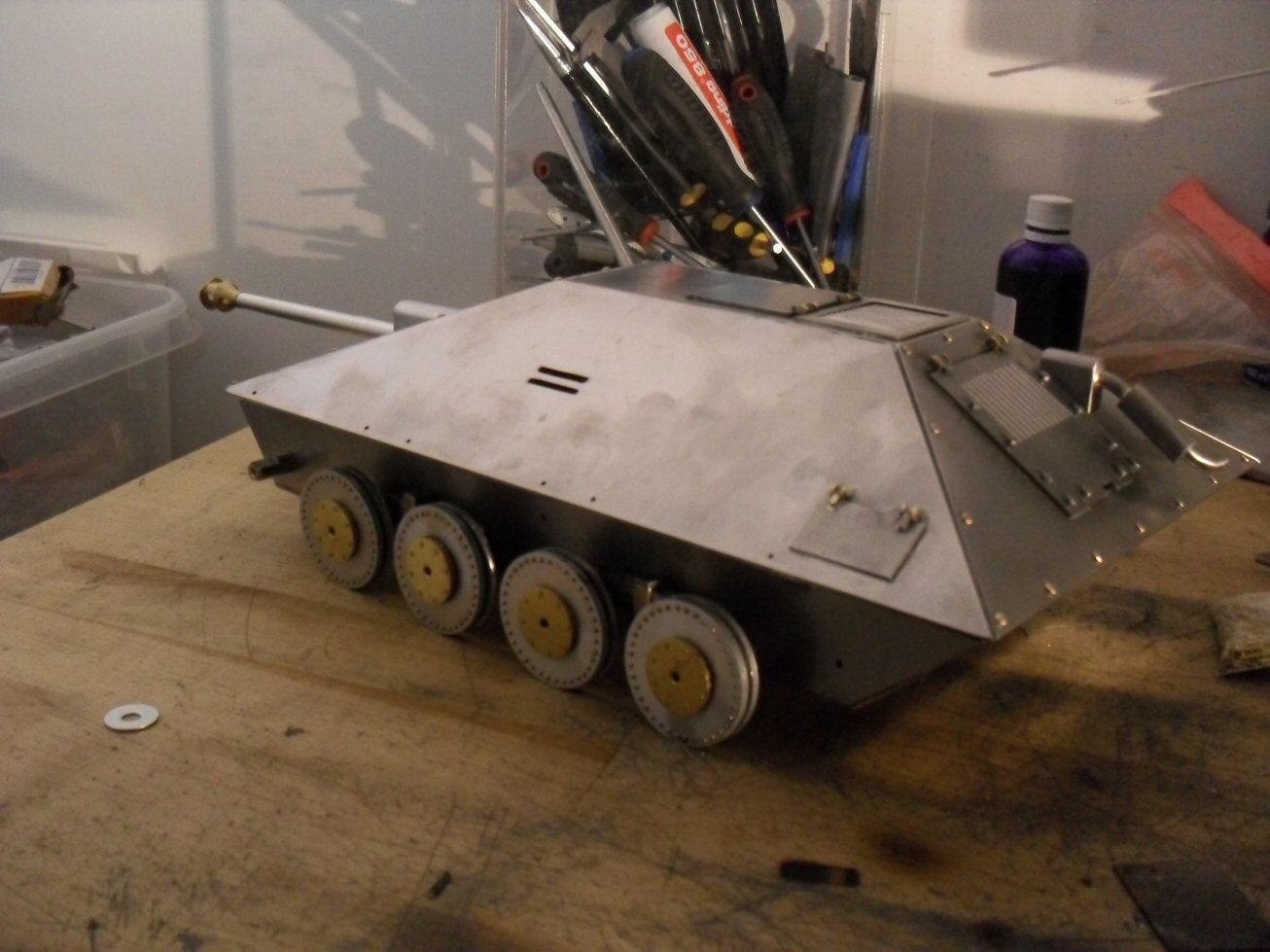
In the end, I just used a hot air gun to get the back plate off, ground a few mm off here and there and then reassembled. Luckily enough this time I got it virtually spot on! A bit of filler and it will be just fine.
P
 12-15-2020, 08:36 AM
#29
Thread Starter
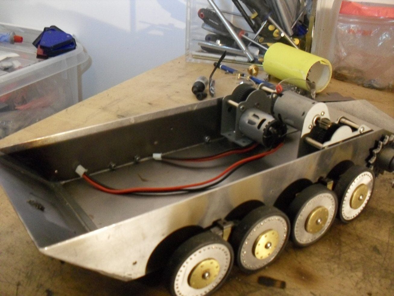
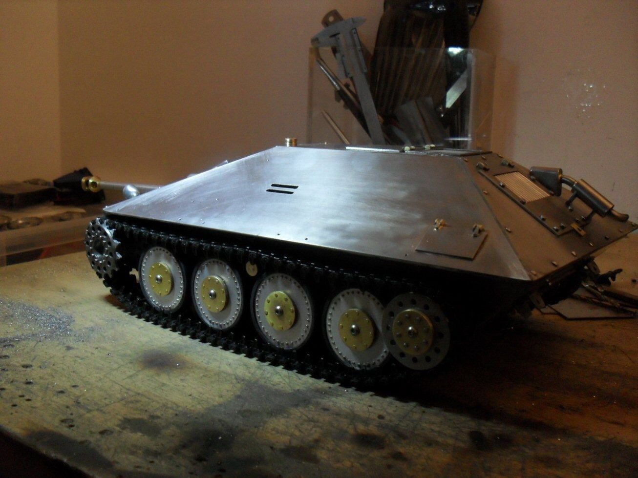
It was time to start on the suspension assemblies. This was striking me as a waste of time as they are essentially non-visible but I need some kind of suspension.
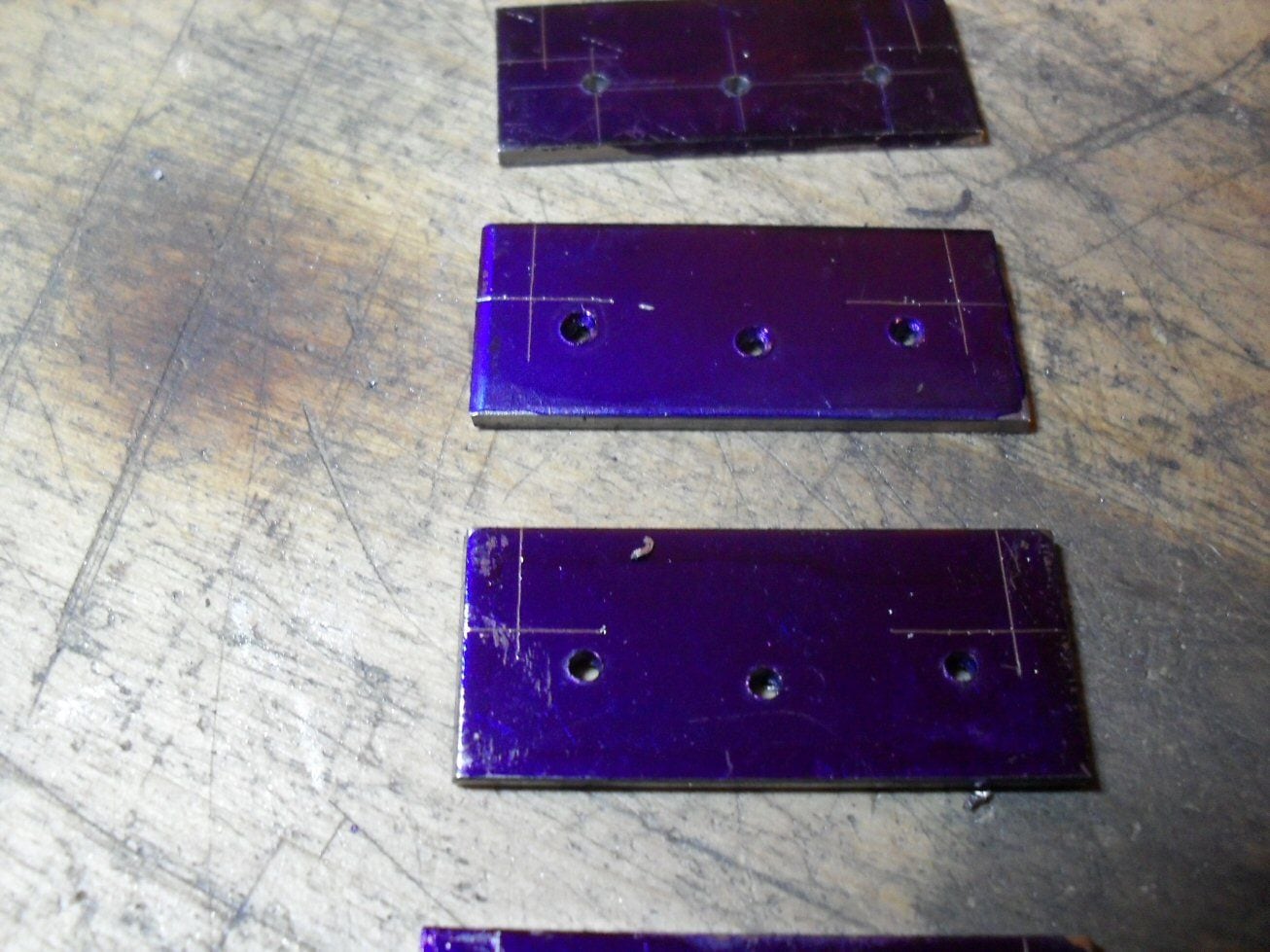
This is tricky as there are a number of bits: a mounting plate on the side of the hull, multicomponent swing arms, the spring mount and the springs themselves.
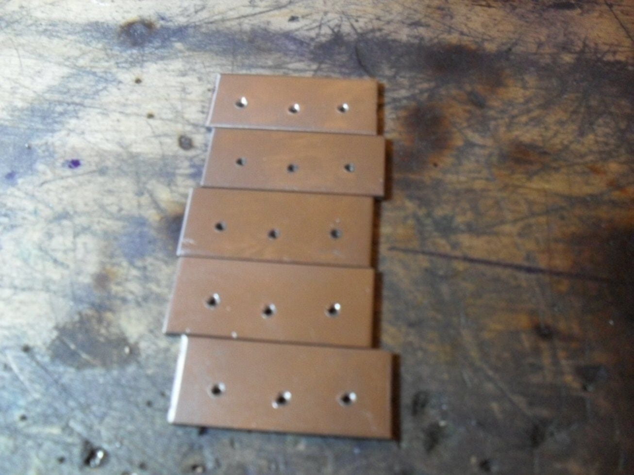
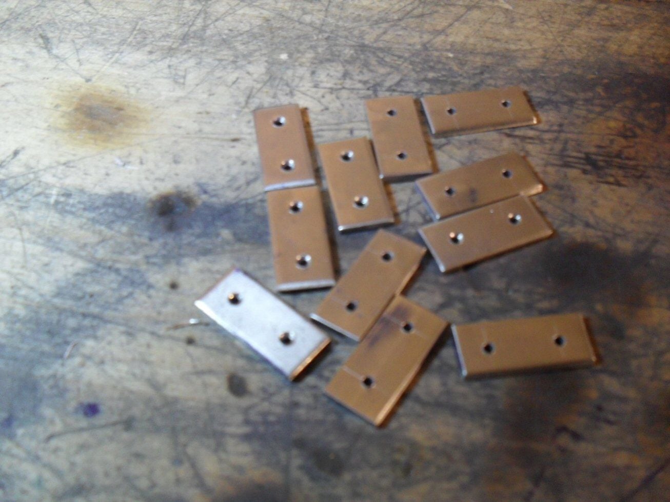
To start, I approached the mounting plates. I first cut out some rectangles of 2mm steel and squared them all up. I need four but made six as there will be some casualties along the way.
There are then three important holes - two that line up (hope so at least) with the marker holes on the hull and which form the pivots for the swing arms and a central hole which forms the bottom mounting point for the spring holder. So I marked off the positions and drilled and chamfered the holes.
Then some corners needed to go so I marked the lines off and used a bit of square tool steel as an edge to file against.
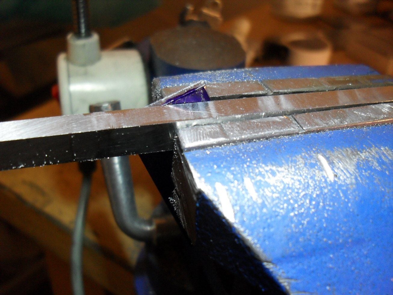
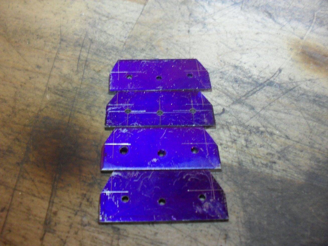
Then there were some curves which I simply roughed out with a Dremel cutting wheel and finished off with a half round file. I then lined all four up using the two placer holes and made sure they were all the same (!) by filing all at once.
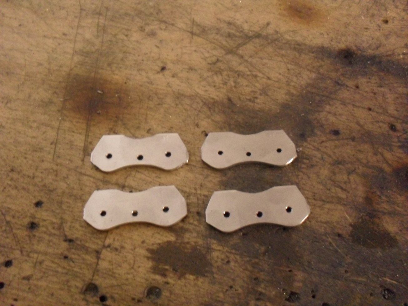
These are obviously failry rough but they are not visible really so I do not care.
I will continue this post after my dinner.
P
This is tricky as there are a number of bits: a mounting plate on the side of the hull, multicomponent swing arms, the spring mount and the springs themselves.
To start, I approached the mounting plates. I first cut out some rectangles of 2mm steel and squared them all up. I need four but made six as there will be some casualties along the way.
There are then three important holes - two that line up (hope so at least) with the marker holes on the hull and which form the pivots for the swing arms and a central hole which forms the bottom mounting point for the spring holder. So I marked off the positions and drilled and chamfered the holes.
Then some corners needed to go so I marked the lines off and used a bit of square tool steel as an edge to file against.
Then there were some curves which I simply roughed out with a Dremel cutting wheel and finished off with a half round file. I then lined all four up using the two placer holes and made sure they were all the same (!) by filing all at once.
These are obviously failry rough but they are not visible really so I do not care.
I will continue this post after my dinner.
P
12-15-2020, 09:13 AM
#30
Thread Starter
The basic part of the swing arms is relatively simple, its a rectangle with two holes at the centres of two radii, one on either end.
I cut out the rectangle (more than I need) and marked off the two holes necessary.
Then I used a pair of hardened filin g buttons to put the radii on either end.
The spring holders are essentially brass bars that hold the springs obviously enough.
I cut out the basic shapes from some brass bar stock and the drilled the one important hole in each one as this acts as a reference point.
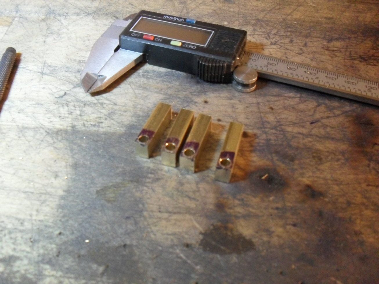
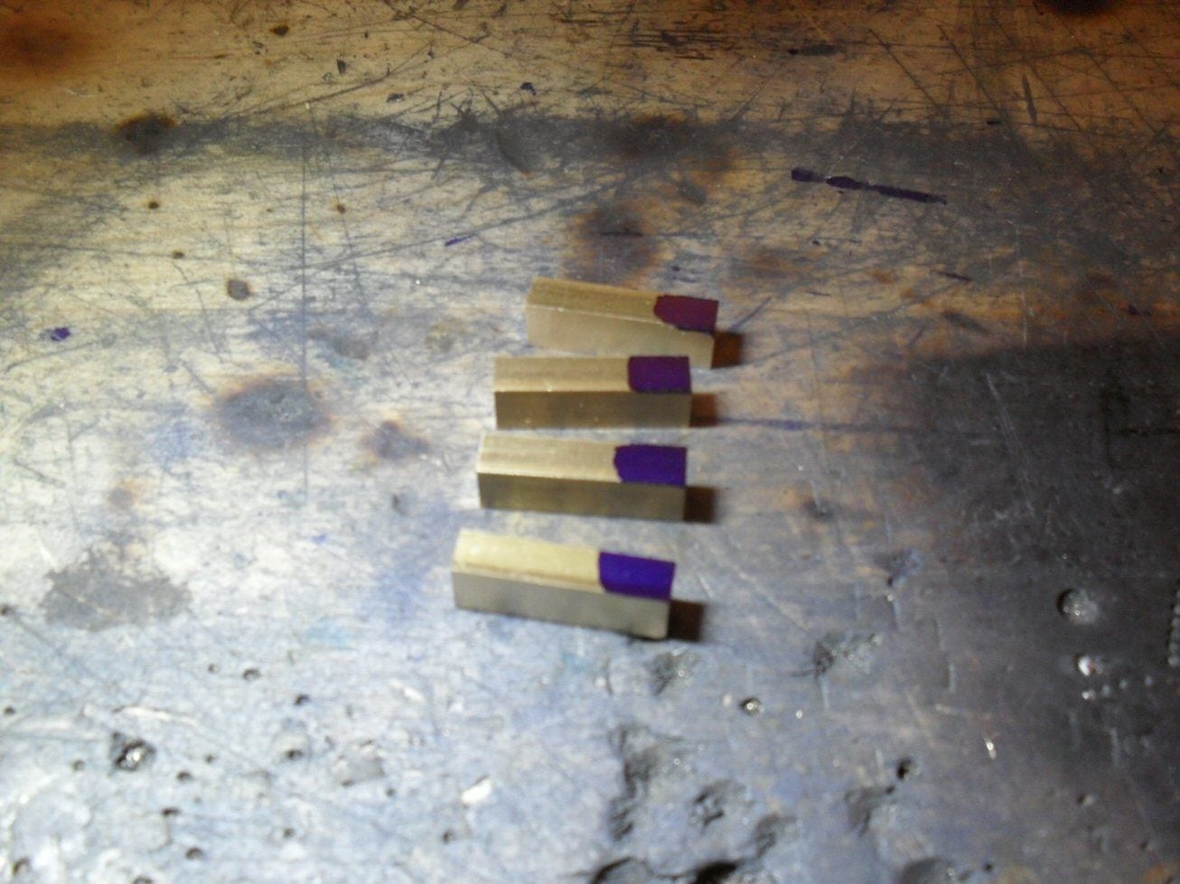
I then stuck them in the vice and filed out a deep slot to a cetain depth. The slot is too deep but I will shorten the arms of it once I know how deep it should be.

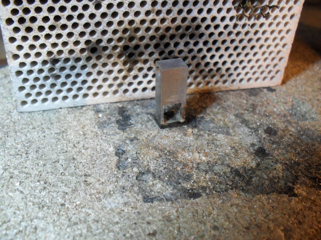
Once I did figure that out I simply shortened the arms and fashioned a cap for the arms from 2mm steel. This was then silver soldered to the arms and forms the top of the holder.
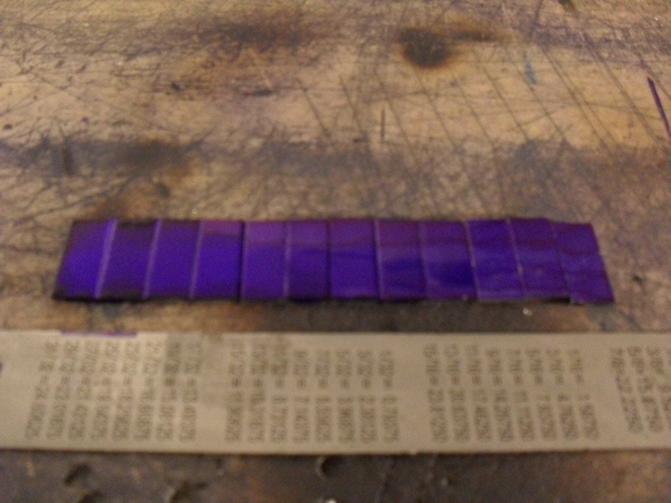
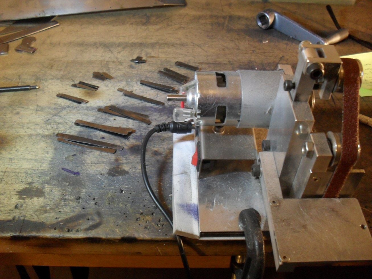
The springs are being made from hacksaw blades which are already hardened and springy.
I used a dermel wheel to cut off the required lengths using water to ensure they didnt too hot and mess them up.
Then I used a mini belt grinder I was given for christmas one year . Dont use it very often but it works, the belts are cheap and available and it was suited to the job. Used it to grind off most of the teeth and round the edges. I think they cost like 20 euro on fleabay or alibaba or wherever. Quite nicely made little thing actually.

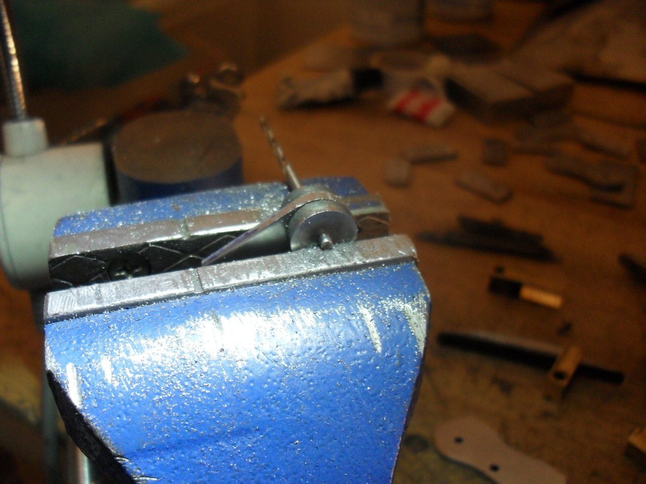
Then I stuffed some of the spring blades into the holder. I had to drill and tap the top cap for an M3 set screw to keep the springs where they should.
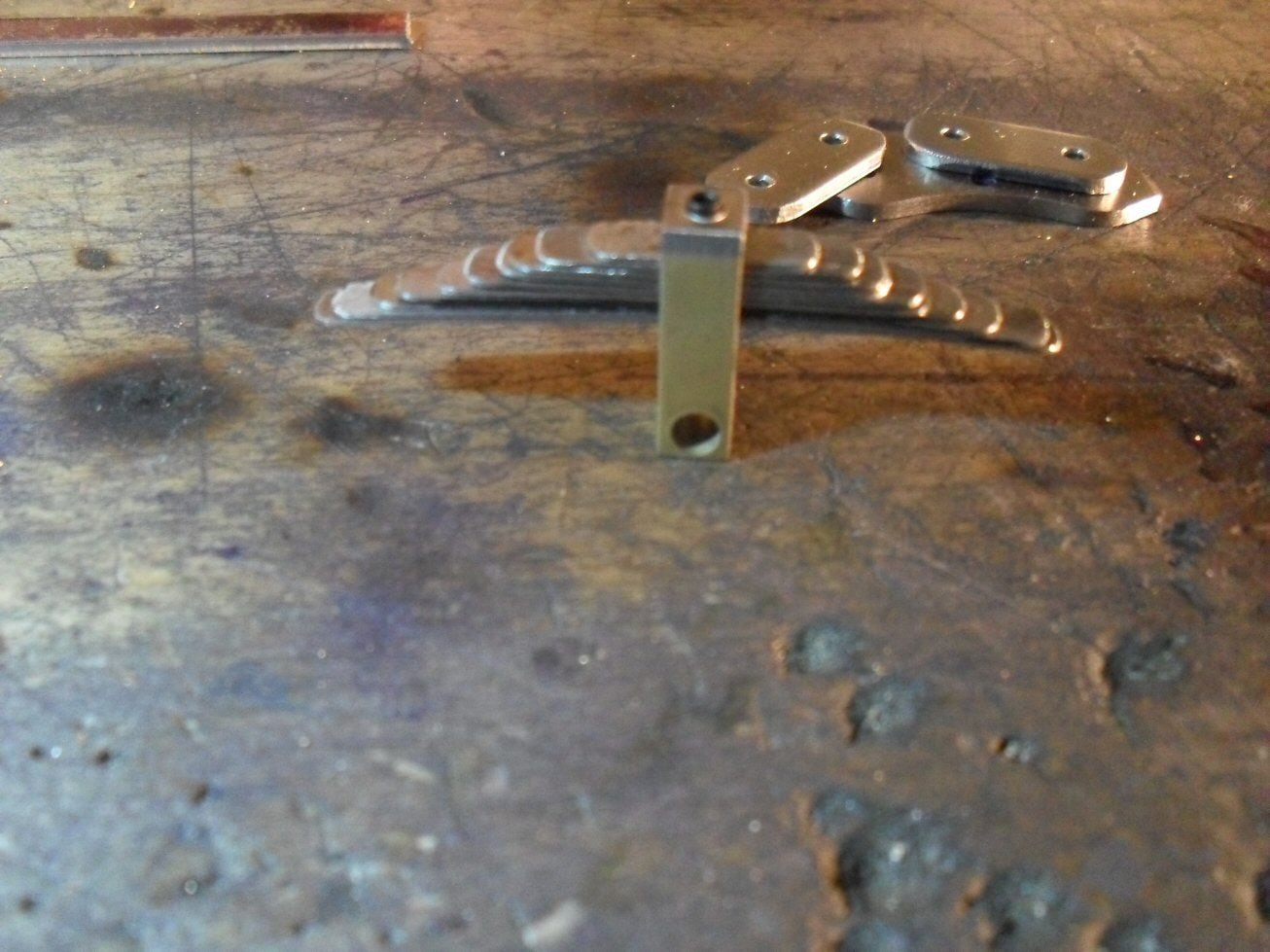
Im in two minds about this. They dont feel very springy (but then again, neither do tension bars) and while they will be invisible, I would prefer a better job on the springs. BUt spring steel is a bi!ch to work with.
Either way, the brass bit needs more work as the bottom needs shaping and some things need soldering.
Hopefully I can progress with that tomorrow-
P
I cut out the rectangle (more than I need) and marked off the two holes necessary.
Then I used a pair of hardened filin g buttons to put the radii on either end.
The spring holders are essentially brass bars that hold the springs obviously enough.
I cut out the basic shapes from some brass bar stock and the drilled the one important hole in each one as this acts as a reference point.
I then stuck them in the vice and filed out a deep slot to a cetain depth. The slot is too deep but I will shorten the arms of it once I know how deep it should be.
Once I did figure that out I simply shortened the arms and fashioned a cap for the arms from 2mm steel. This was then silver soldered to the arms and forms the top of the holder.
The springs are being made from hacksaw blades which are already hardened and springy.
I used a dermel wheel to cut off the required lengths using water to ensure they didnt too hot and mess them up.
Then I used a mini belt grinder I was given for christmas one year . Dont use it very often but it works, the belts are cheap and available and it was suited to the job. Used it to grind off most of the teeth and round the edges. I think they cost like 20 euro on fleabay or alibaba or wherever. Quite nicely made little thing actually.
Then I stuffed some of the spring blades into the holder. I had to drill and tap the top cap for an M3 set screw to keep the springs where they should.
Im in two minds about this. They dont feel very springy (but then again, neither do tension bars) and while they will be invisible, I would prefer a better job on the springs. BUt spring steel is a bi!ch to work with.
Either way, the brass bit needs more work as the bottom needs shaping and some things need soldering.
Hopefully I can progress with that tomorrow-
P
12-15-2020, 10:33 AM
#31
Nice work. I have a similar sander and I use mine all the time on brass and styrene. I also have a full sized belt/disc sander in the garage to use on harder materials, but it gets a lot less use now that I have the little one on my bench. I also have a miniature chop saw and Proxxon table saw have sped up my scratch building all while making it more precise. The mini table saw is great for sheet acrylic and thicker sheet styrene.
12-16-2020, 09:16 AM
#32
Nice trick using junior hacksaw blades, have an old Tamiya KT single motor clutch steering model. This looks like the answer to the weak suspension on it. Find it hard enough working with styrene , doing one all metal is amazing.
12-20-2020, 12:22 PM
#33
Thread Starter
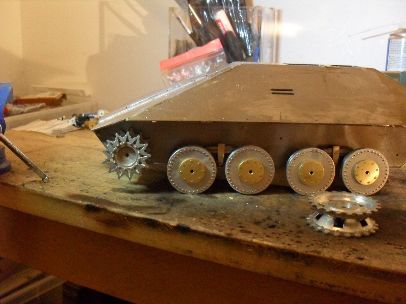
It was time to start on the wheels which, for a nice change, there are only eight of. After much to-ing and fro-ing I decided on one guide horn Pz II tracks as opposed to the sherman tracks as I agree with the opinion that sherman tracks are obviously sherman tracks.
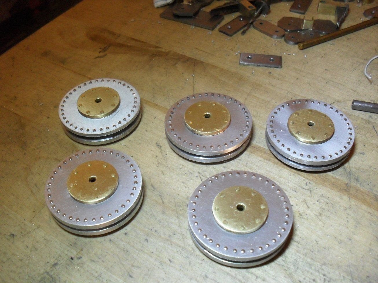
For the wheels, I am using a set of aluminium pulley type things from an old Hewlett Packard plotter thing (large sheets of paper) I think. Its been a few years since I got them. They had a plastic rim type of thing which had to come off and a plastic hub which also came off. Then all they needed were sanding and a minor trim here and there.
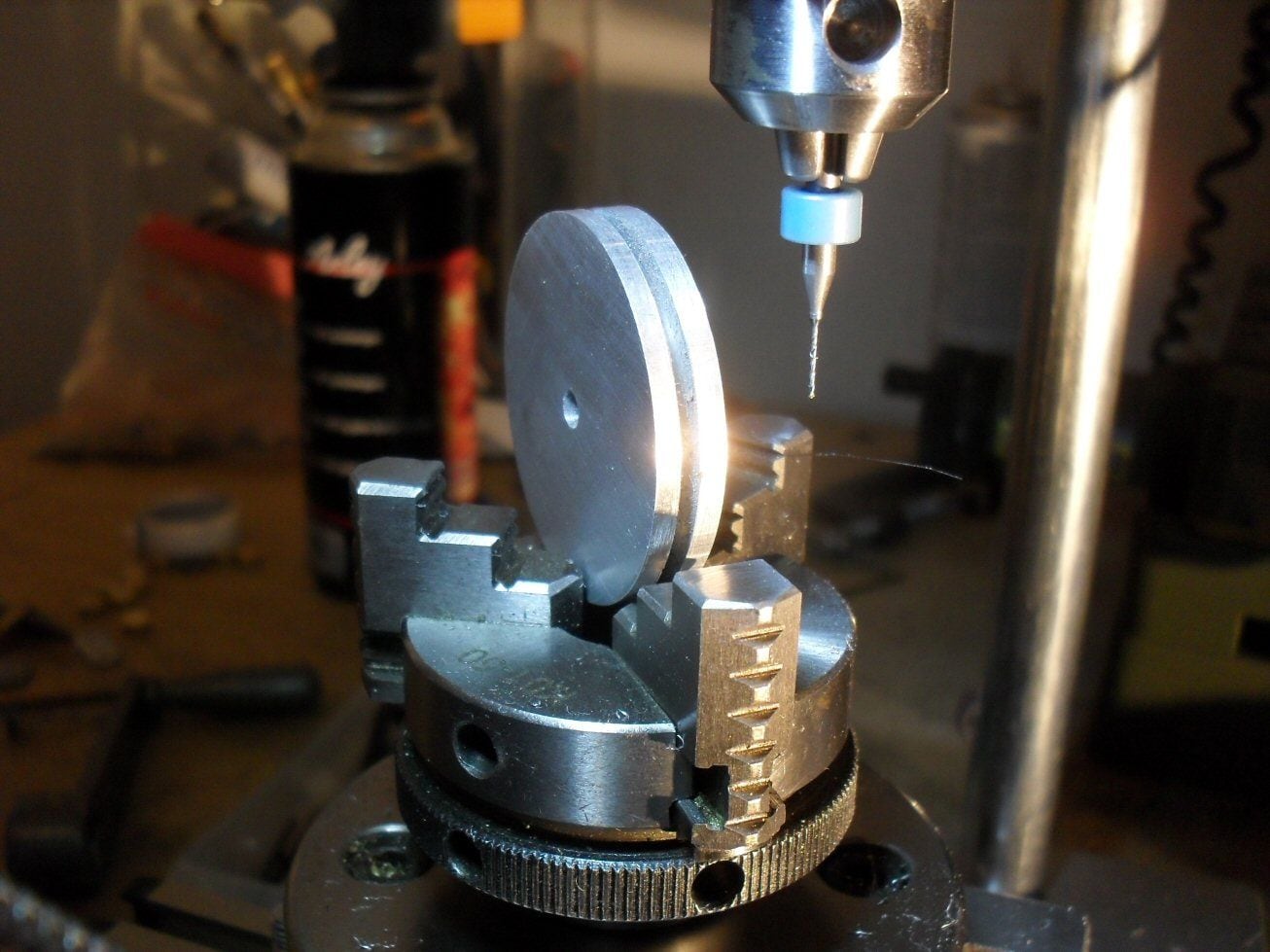
Around the outside, 36 0.6 mm holes were drilled. The actual wheels had a load of rivets or bolts or something around teh edges. Buying tiny rivets (300) from some modellbau is crazy expensive so Im using shirt pins which cost essentially nothing. They have a shaft diameter of 0.6 mm and I simply cut off most of the shaft and press fit them in. Tedious work indeed.
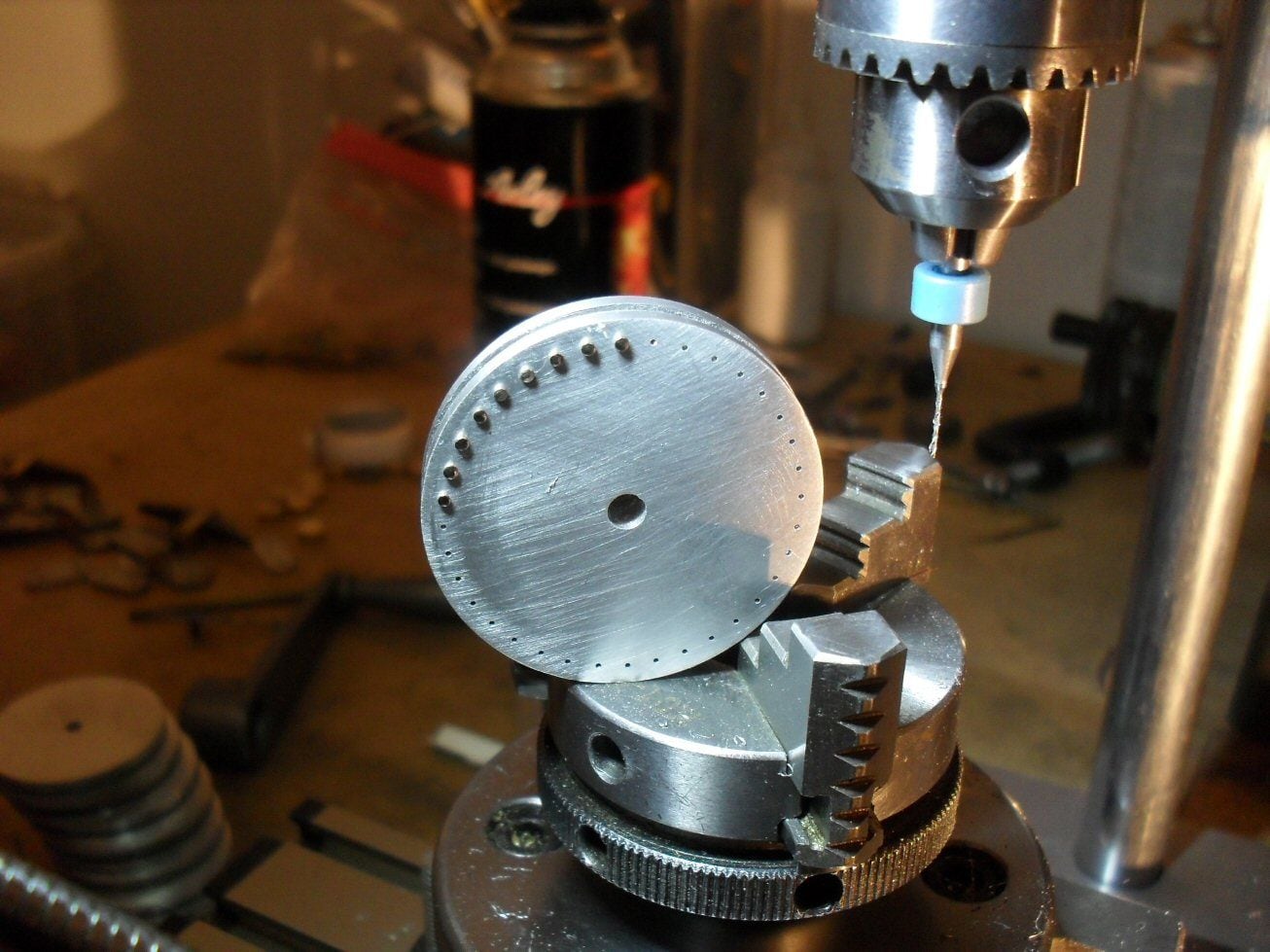
I then got brass discs I had from a previous project and just centre bored them to 3 mm. Then I drilled holes around teh edges and stuffed picture framers tacks into the holes. I trimmed off the pointy bits and simply peened the backsides.
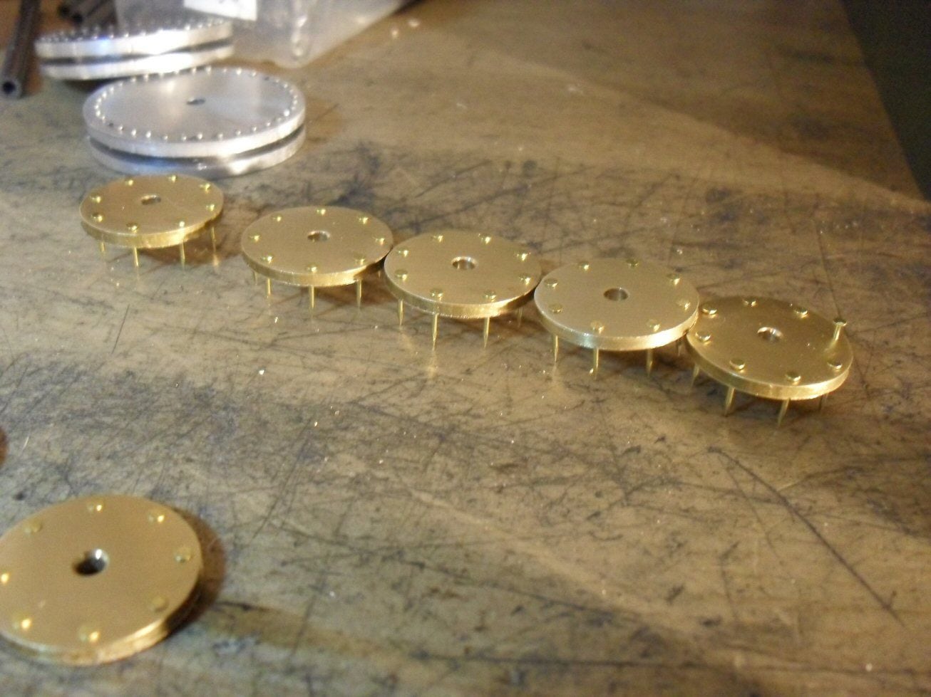
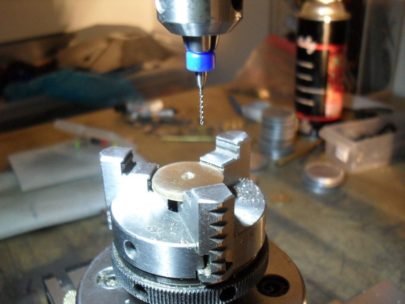
lengths of 6mm OD brass tube were cut with a tube cutter. These had to be soldered on dead centre to the back side of the brass discs. I centered the rotary table on the Proxxon and then inserted a centre (a deburrer actually) in teh chuck. This then allowed me to centre the brass tube over the centre hole on the disc. Then I soldered it on.
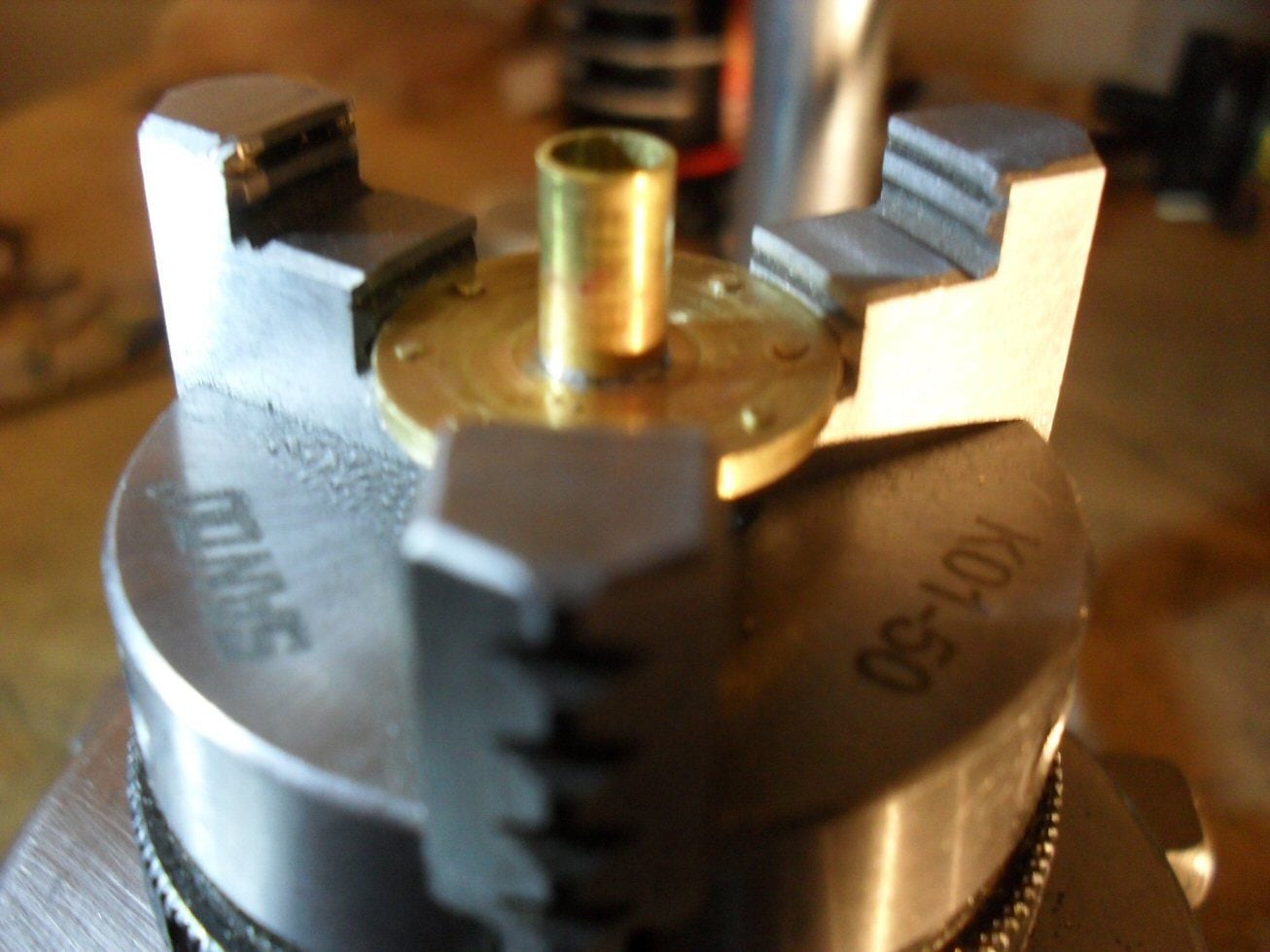
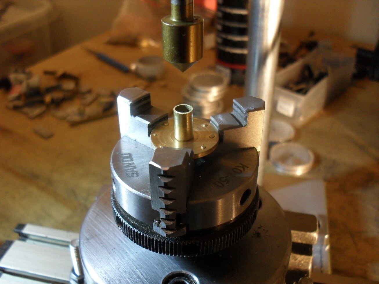
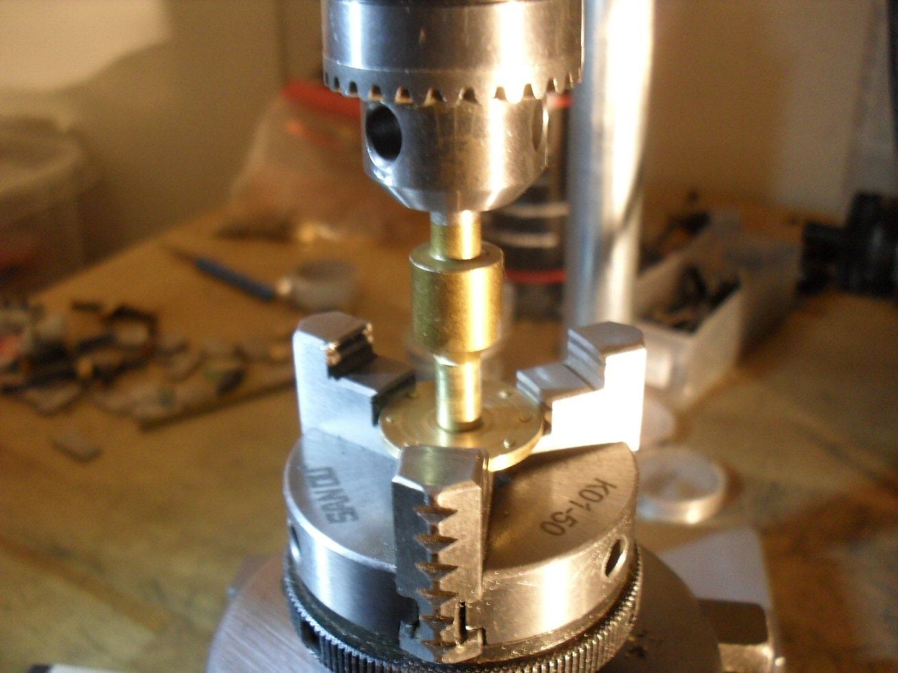
These hubs were then press fit into the aluminium wheels.
Tires will be acertal/delrin but the tuvbe I ordered has not arrived thanks to covid/Christmas I guess.
P
For the wheels, I am using a set of aluminium pulley type things from an old Hewlett Packard plotter thing (large sheets of paper) I think. Its been a few years since I got them. They had a plastic rim type of thing which had to come off and a plastic hub which also came off. Then all they needed were sanding and a minor trim here and there.
Around the outside, 36 0.6 mm holes were drilled. The actual wheels had a load of rivets or bolts or something around teh edges. Buying tiny rivets (300) from some modellbau is crazy expensive so Im using shirt pins which cost essentially nothing. They have a shaft diameter of 0.6 mm and I simply cut off most of the shaft and press fit them in. Tedious work indeed.
I then got brass discs I had from a previous project and just centre bored them to 3 mm. Then I drilled holes around teh edges and stuffed picture framers tacks into the holes. I trimmed off the pointy bits and simply peened the backsides.
lengths of 6mm OD brass tube were cut with a tube cutter. These had to be soldered on dead centre to the back side of the brass discs. I centered the rotary table on the Proxxon and then inserted a centre (a deburrer actually) in teh chuck. This then allowed me to centre the brass tube over the centre hole on the disc. Then I soldered it on.
These hubs were then press fit into the aluminium wheels.
Tires will be acertal/delrin but the tuvbe I ordered has not arrived thanks to covid/Christmas I guess.
P
12-21-2020, 11:42 AM
#34
Wow, nice metal work on those wheels!!!
12-31-2020, 09:31 AM
#35
Thread Starter
Ive run into a real snag with this build. The Stug III sprocket I was going to use isnt going to cut it all.
I have the running gear built mostly and once I put them one the tank, I could see that the sprocket is way to big - it should be smaller by a good bit. As it stands, there isnt enough "lift" on teh front end - the sprocket is too close to the ground and it looks odd.
The only way to salvage this - as everything else has been built up around the Pz III sprcoekt and track -is to figure out a smaller diameter sprocket with the same pitch for the teeth (ie. a smaller diameter but with teeth that will engage with the Pz II sprocket. This I do not know how to figure out.
Is there anyone around here who knows how to do those types of calculations?
P
12-31-2020, 10:52 AM
#36
Thread Starter
To better illustrate this complete cockup......
This is the tank with pz iii sprockets which are wider than they should be:
This is it with a sherman sprocket:
The sherman sprocket is the right size. But I was geared up for Pz ii sprocket and the wheels are made for that track.
So Im in a right pickle.
I can proceed with teh Pz III sprocket and track but it looks like complete cack.
I can change to the sherman set up but will have to rebore the drive shaft hole (not simple) and remake the wheels in a big way. In addition, if the sherman track is as wide as the sprocket (which it must be) , that is going to be too wide for teh tank.
In an ideal world, I could get hold of a smaller sprocket that has the right pitch for a pz ii track. Thats never going to happen so in reality, Im going tohave to try and cobble one together.
The current Pz III sprocket has an outer diameter of 52 mm and 21 teeth. I can calculate the arc lenght and so on but Ive never cut a gear in my life and am not set up to do so so I would have to get help.
Any opinions would be gratefully recieved as Ive really stepped in the doodoo.
I should have heeded RC_BObM and done the running gear first but I really thought I had got my figures in order when I planned it out.
P
12-31-2020, 02:38 PM
#37
Lposter,
Sorry to hear of your dilemma. Yeah these things are frustrating. As talented as you are with metal work I think you can make a sprocket. You might be able to draw it up on paper and visually fit the track to teeth opening position. You will obviously need fewer teeth than the PZ III sprocket. I don't have any PZIII track - otherwise I could help. Machining it by degree's (between teeth) is possible but you need equal spacing around your new diameter (hopefully this makes since). Another idea would be to have sprocket rings laser cut to bolt to an new sprocket hub - but you need CAD and output DXF file for laser cutter for this.
All scratch project I build - I design in CAD first before cutting metal, and always design / make tracks +running gear first. This helps resolve agony you are feeling new. But sometimes there's still problems.
It is possible to machine a new sprocket by hand, assuming you have lathe, mill and rotary table - which it looks like you do.
Here's one method (assuming you don't have indexer):
1) Draw out on paper the teeth location on new sprocket diameter. Obviously you need whole number of teeth (ie cannot have 13 1/2 teeth). Gage by eye where tooth should be relative to opening in track. Adjust your diameter till your track fits sprocket diameter and pitch of teeth. At least on paper!
2) Machine two new hub to desired diameter and "H" shape. I suggest aluminum. Not a bad idea to make an extra piece to practice on.
3) Put blank sprocket in mill/rotary table. Center mill on center of rotary table. Move table over one axis, X or Y to machine teeth.
4) Glue paper template to your hub. Template should be same diameter of sprocket and show your desired tooth locations.
5) Machine the teeth using ~3-4mm end mill to the template. Machine teeth equal distance on each side of tooth mark location. You can get surprisingly close enough by eye.
6) It would be ideal if your mill cutter is long enough to machine both sprocket rings on hub at one time (so teeth are all in same location) otherwise you have align teeth on second side = major pain. Take small cuts until desired tooth depth is reached. Index rotary table to next tooth - repeat till all teeth are machined. Machine all teeth to same depth, equally around circle
7) File teeth to triangular shape once all teeth machined. Hopefully it mates up to track.
8) Repeat with second hub.
This is a good bit of work - but not impossible if you have decent machining skills. Don't give up now - you've come too far!
Another option - use Sherman sprocket and track. Machine new faux hub cap to disguise Sherman sprocket - pretty easy to do.
Bob
12-31-2020, 03:11 PM
#38
Thread Starter
I dont actually have a lathe or mill but Im fairly happy using a coping saw and filing to shape.
the sherman set up may be the way to go. Wheels are easier than a sprocket.
p
the sherman set up may be the way to go. Wheels are easier than a sprocket.
p
01-12-2021, 10:07 AM
#39
Thread Starter
Hello
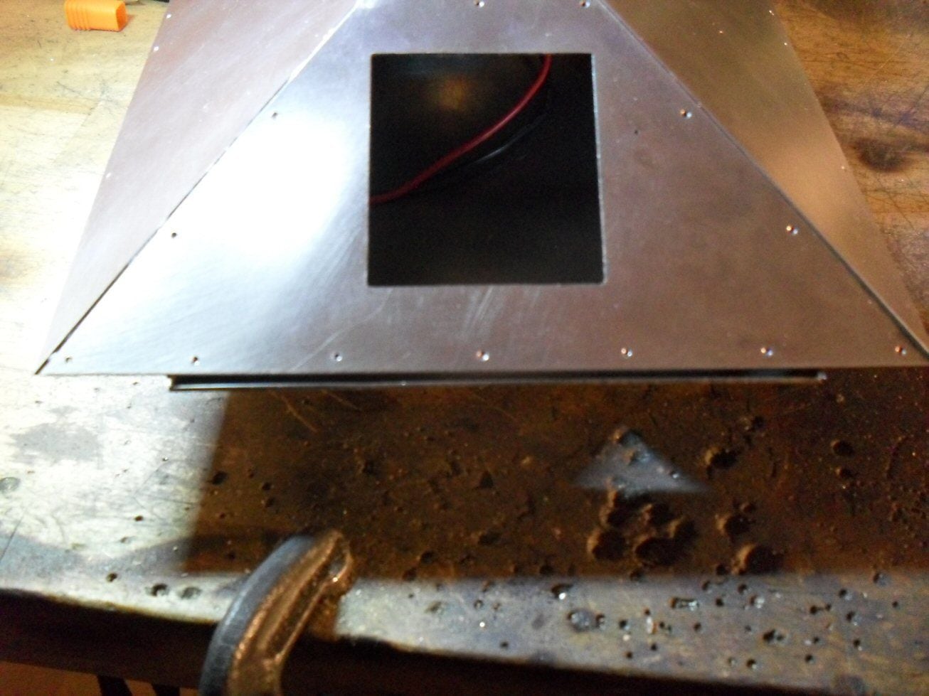
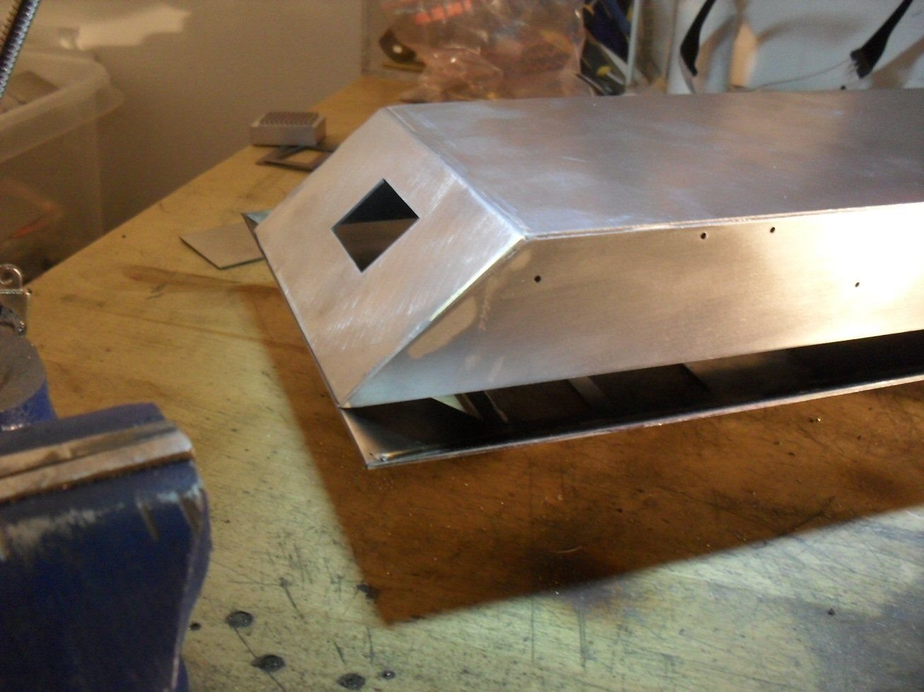
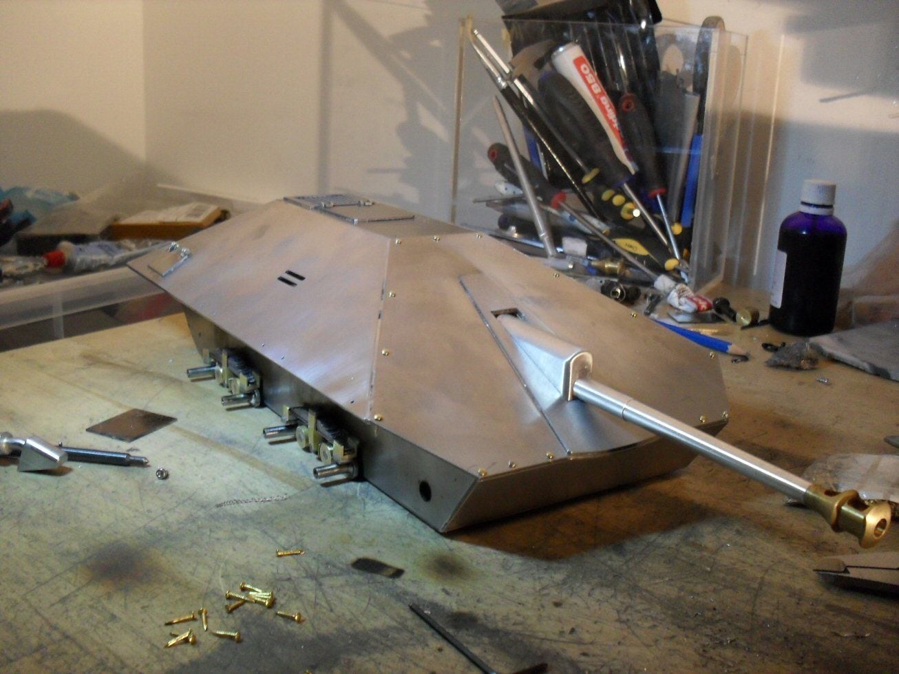
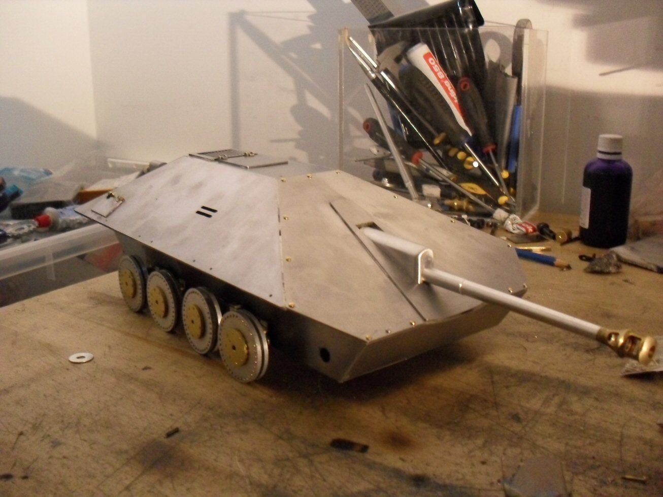
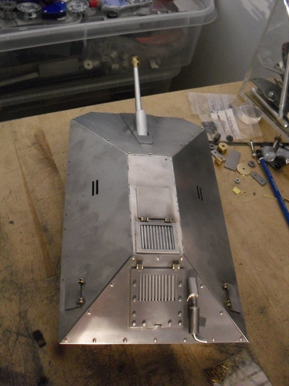
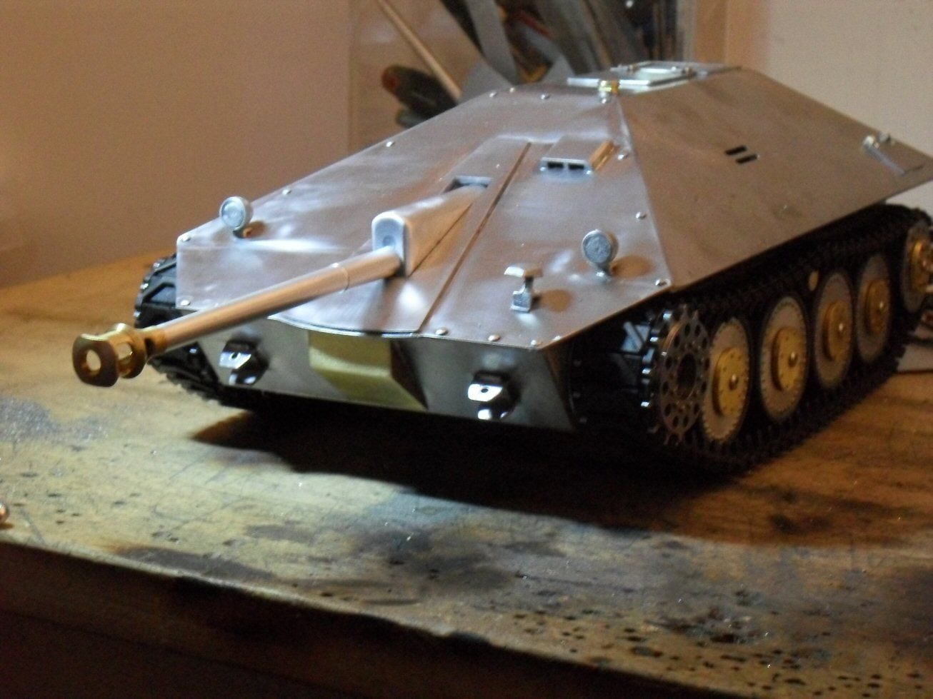
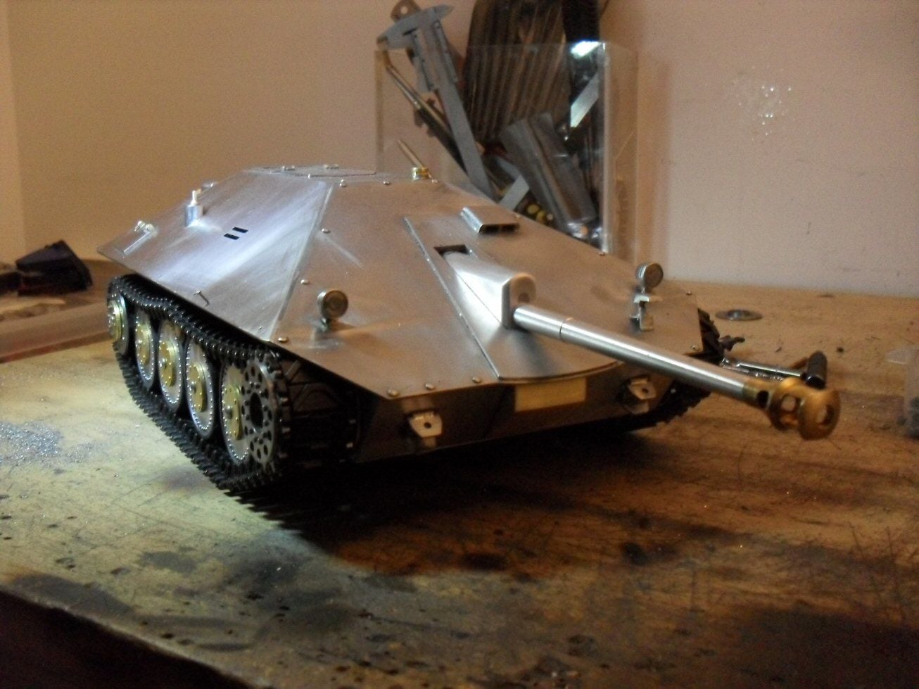
Just in case anyone thinks Ive been slacking..... despite the problem with the sprocket (which I am working on solutions for), I didnt waste time and did some bits on the hull.
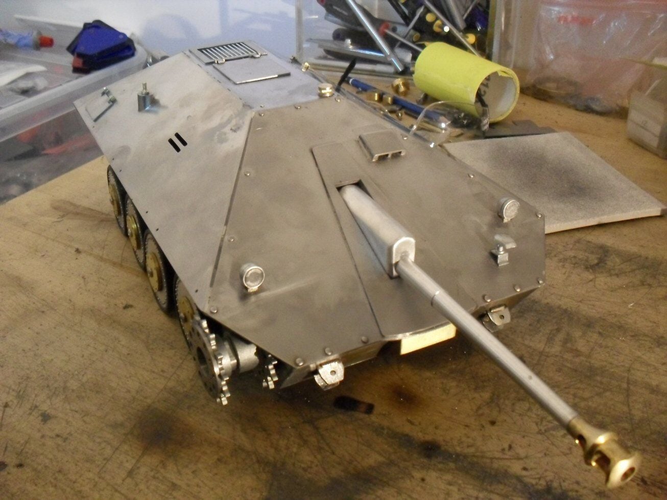
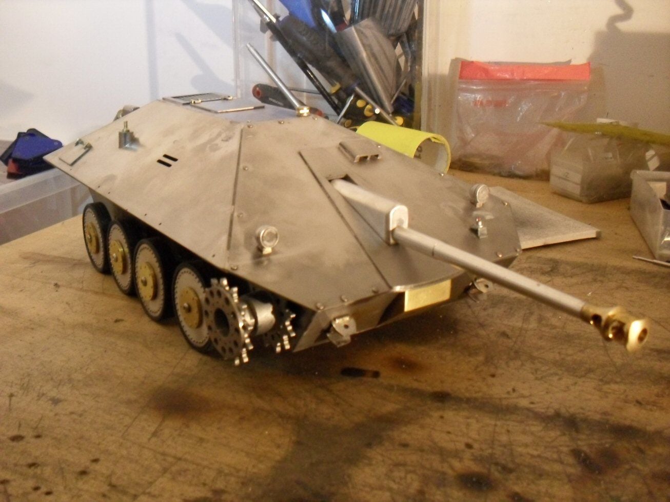
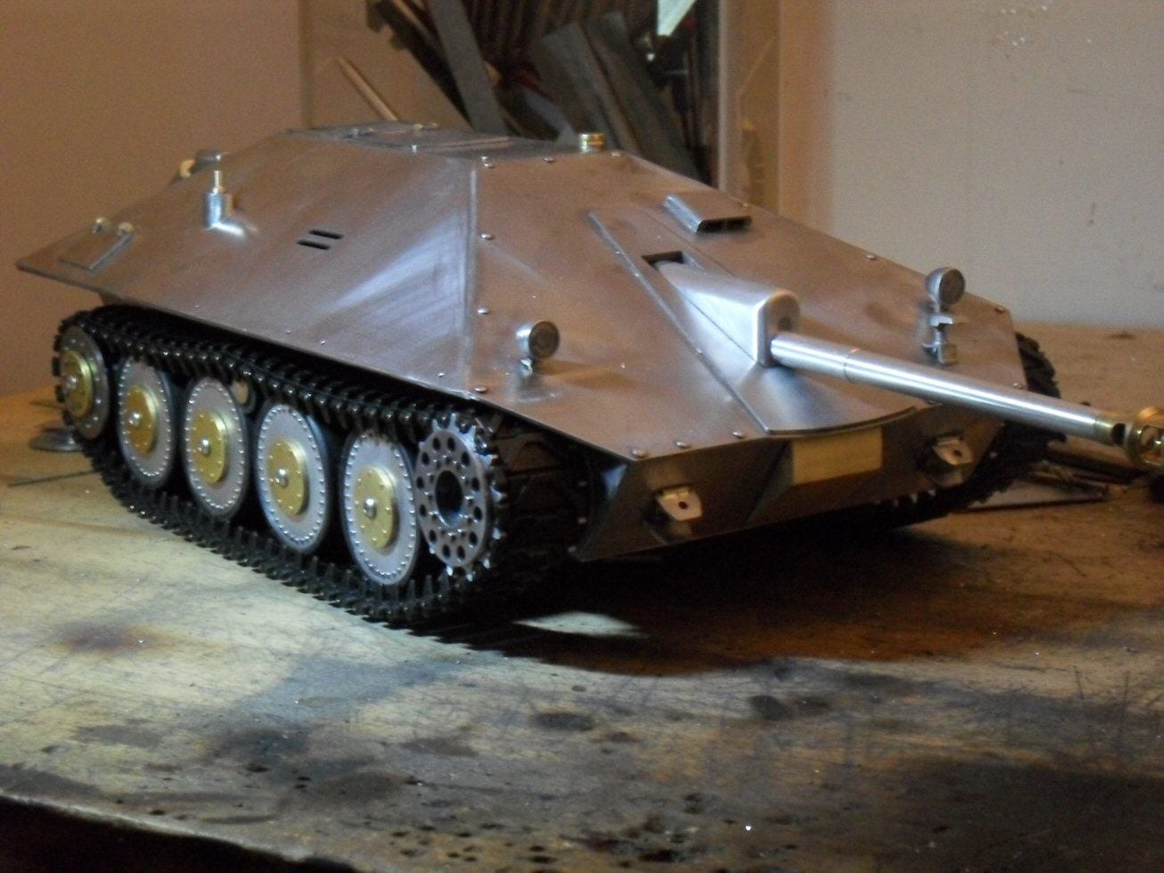
The grills on the top and back are simply Intel heat sinks from an old pc, filed down and mounted from the back. The gun I bought from RCTank, the exhaust is scratched and 90% done.
The front glacis needs some bits, the rear glacis needs finishing and the entire body needs filler and sanding. The lower hull needs a lot of work (hatches, idlers, return rollers, skirts, hitches).
I got some PzIII lights for it but Im not sure as to them being possibly too big and they have no lenses ( I dont know how to make them either). A notek light needs fitting as well.
P
Just in case anyone thinks Ive been slacking..... despite the problem with the sprocket (which I am working on solutions for), I didnt waste time and did some bits on the hull.
The grills on the top and back are simply Intel heat sinks from an old pc, filed down and mounted from the back. The gun I bought from RCTank, the exhaust is scratched and 90% done.
The front glacis needs some bits, the rear glacis needs finishing and the entire body needs filler and sanding. The lower hull needs a lot of work (hatches, idlers, return rollers, skirts, hitches).
I got some PzIII lights for it but Im not sure as to them being possibly too big and they have no lenses ( I dont know how to make them either). A notek light needs fitting as well.
P
01-25-2021, 10:33 AM
#41
Thread Starter
Got some more work done on the top hull. I tried the staples and plastic headlight tip I got on another thread but after ending up burning the plastic, my fingers and the sleeve of my sweater, I ended up with two lenses of dubious quality.
But Im using them.
I started modding the sherman sprockets using large steel washers which I still have to finish. Mounted my road wheels and the gearboxes. The position of the gears had to be raised 7 mm so they are standing on a set of brass standoffs. Lucky for me the top of the hull still fits.
next will be the idlers and the solitary return rollers. Then the skirts.
P
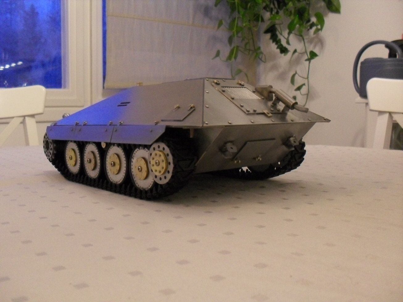
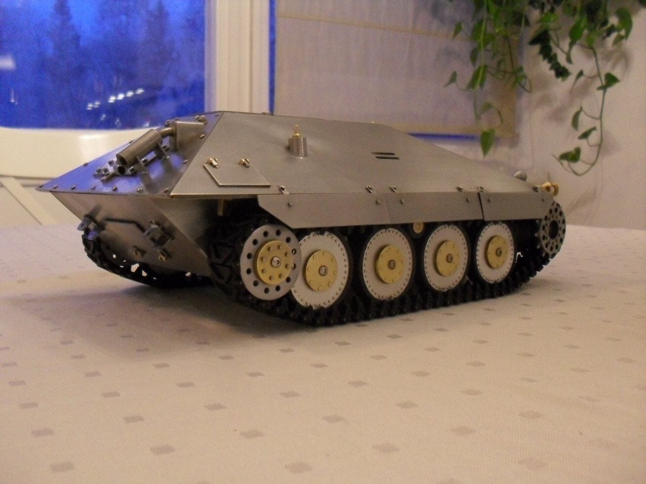
01-29-2021, 07:40 AM
#42
Thread Starter
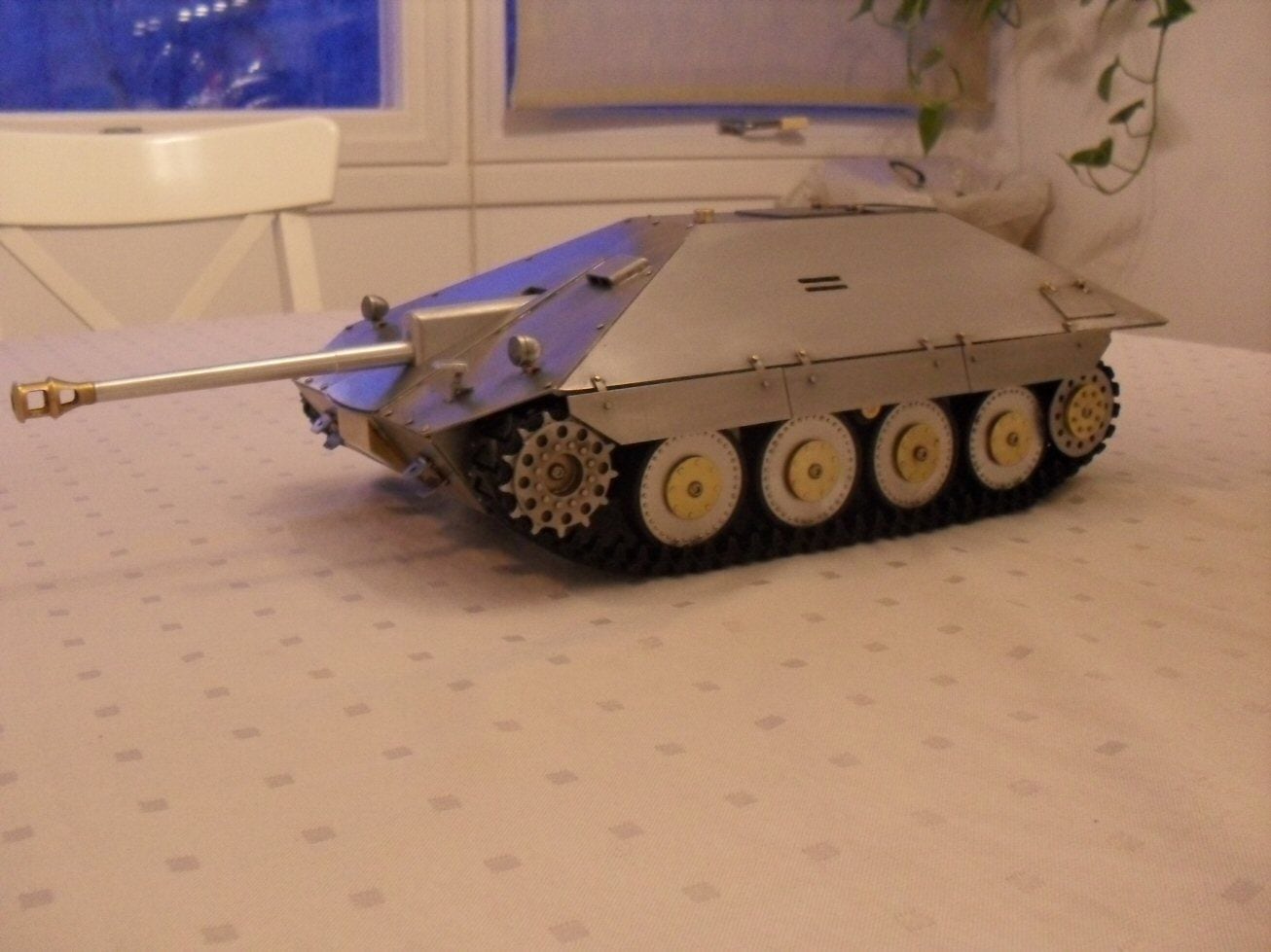
Big milestone for the Maresal today...full set of wheels and a set of tracks. Still, filthy, still not finished.
But I reckon the finishing line is in sight and a final spurt to get the skirts done should be doable.
For some reason its reminding me more of a Jagdpanther than the Hetzer its supposed to inspire but who knows......
P
But I reckon the finishing line is in sight and a final spurt to get the skirts done should be doable.
For some reason its reminding me more of a Jagdpanther than the Hetzer its supposed to inspire but who knows......
P
01-29-2021, 10:48 AM
#44
Looks really good! Glad you got the sprocket situation worked out. The Sherman sprocket looks great with the faux cover plate. Tracks actually look good too. Glad you didn't give up on it!

B
B
01-29-2021, 05:17 PM
#45
Wow, it looks great!!! Your metal work is excellent!!!
01-31-2021, 08:13 AM
#46
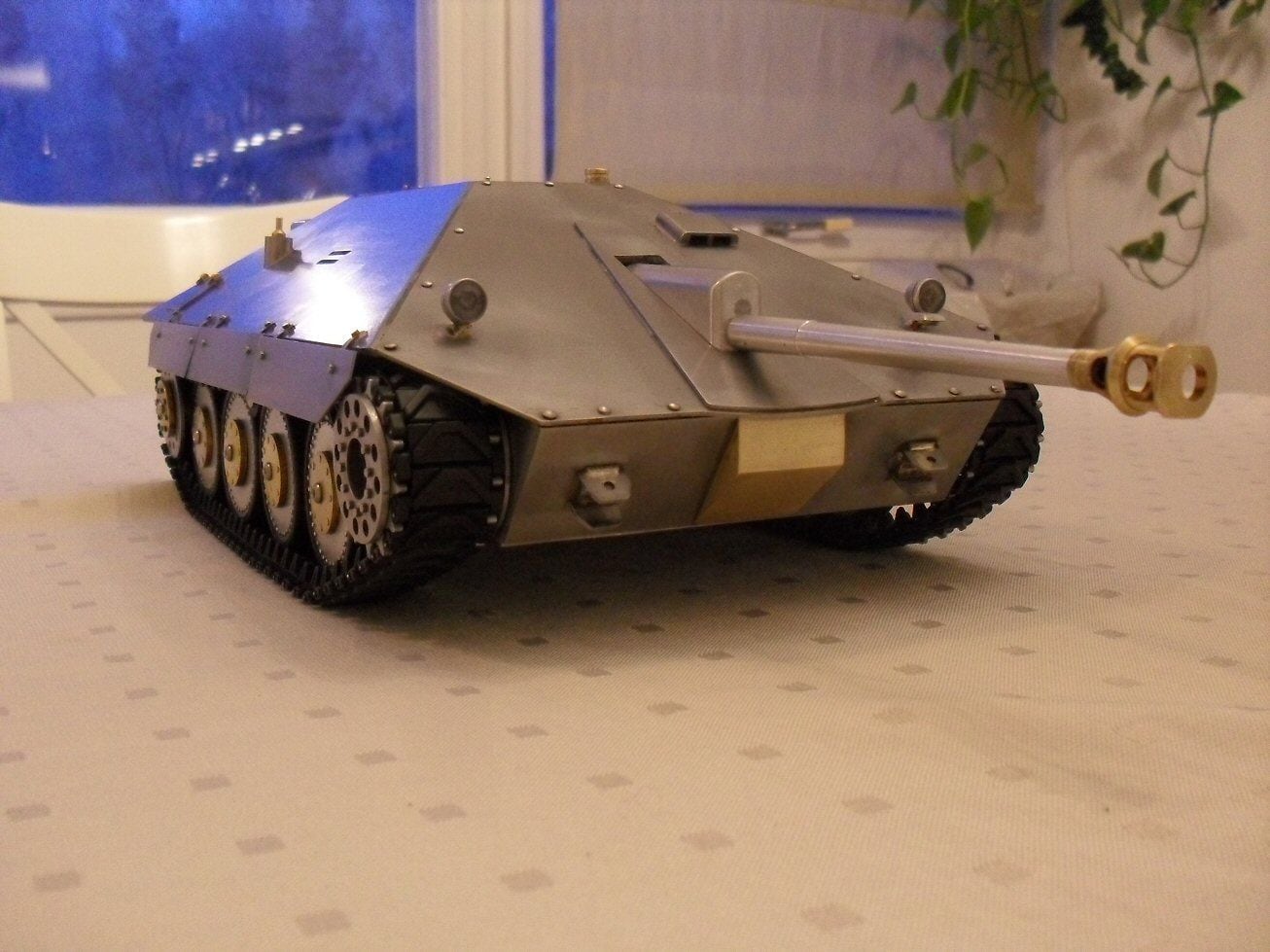
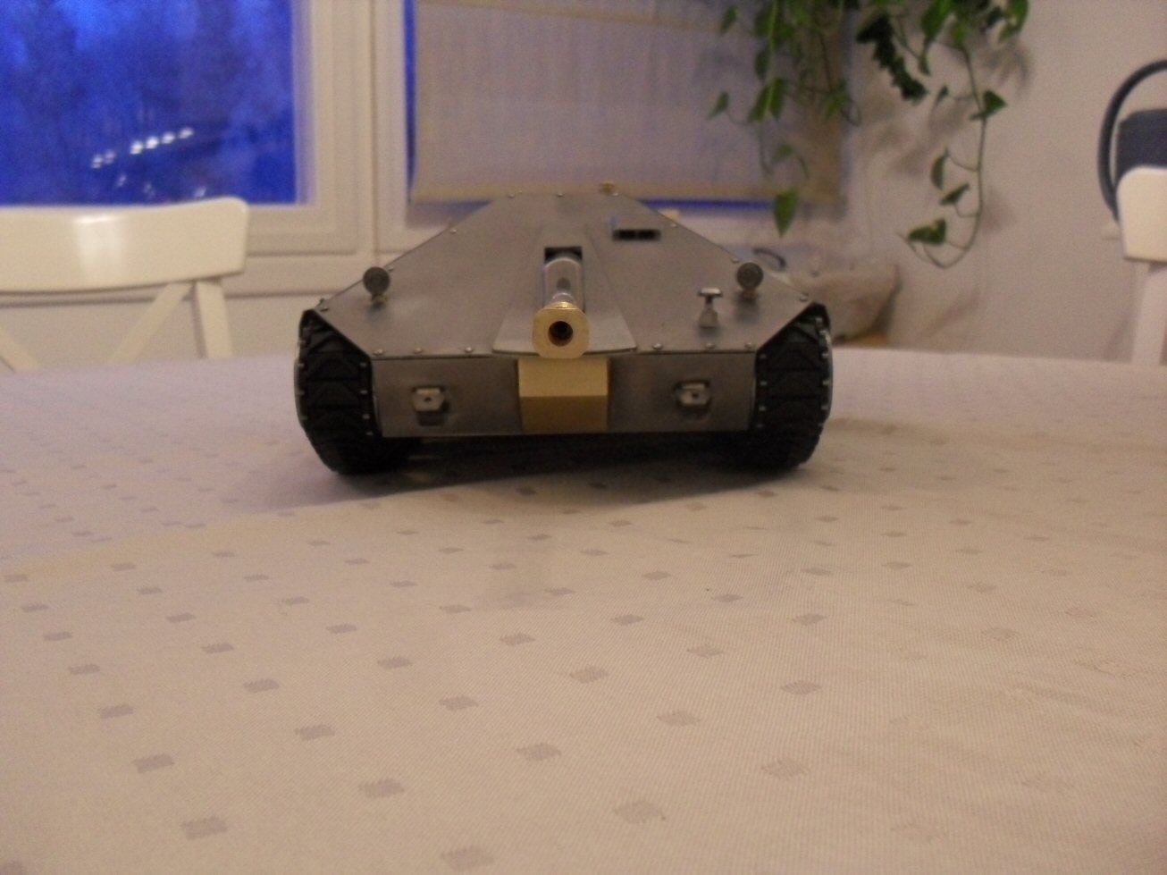
Thread Starter
Hello
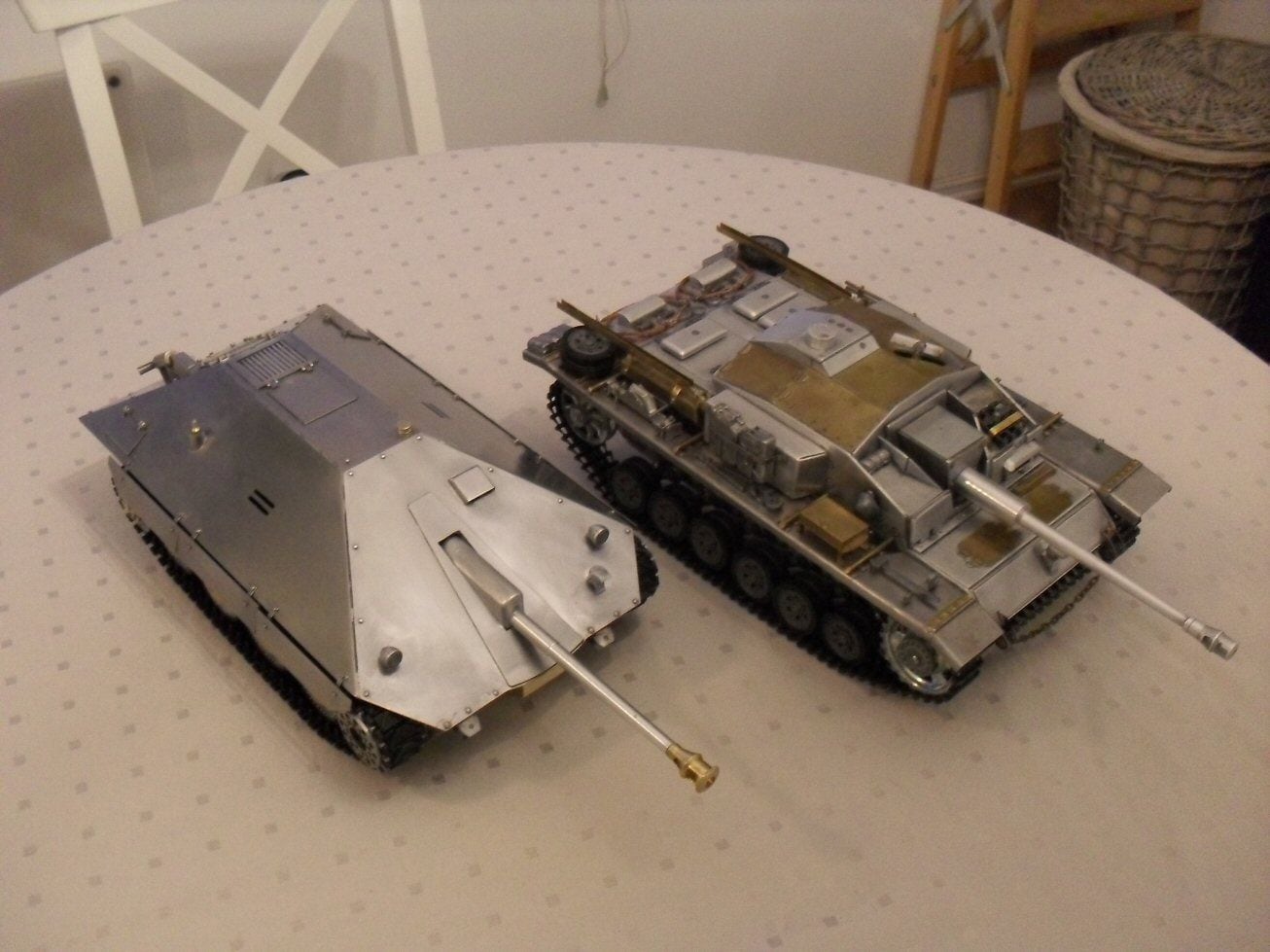
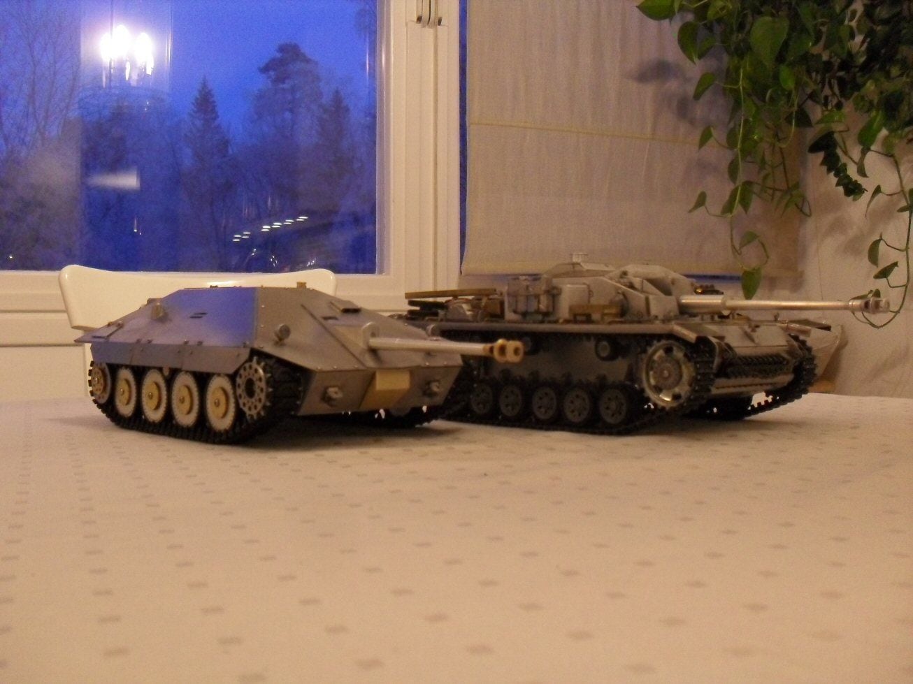
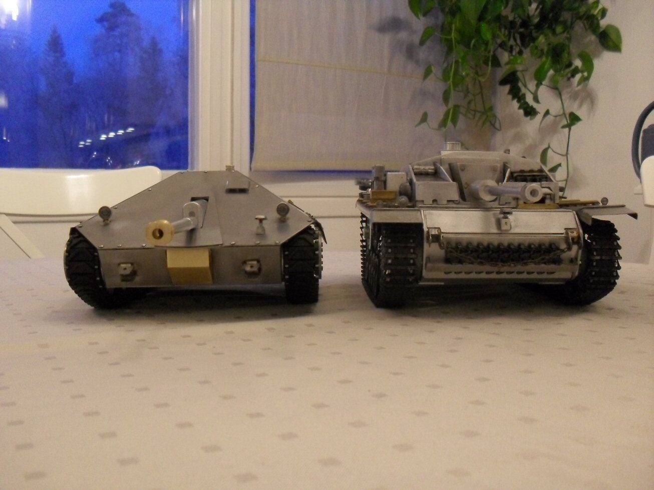
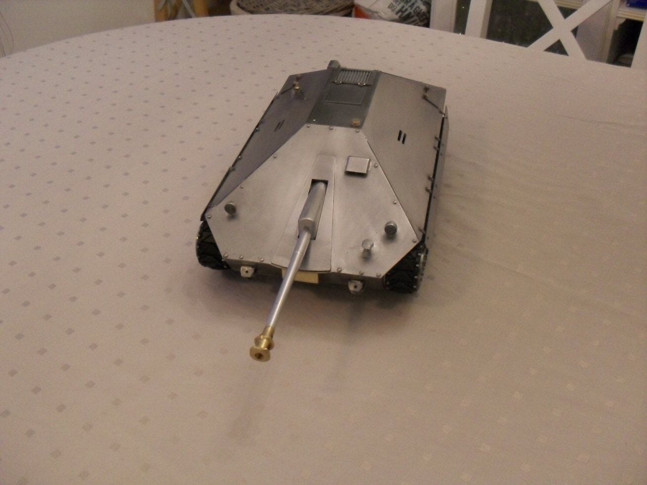
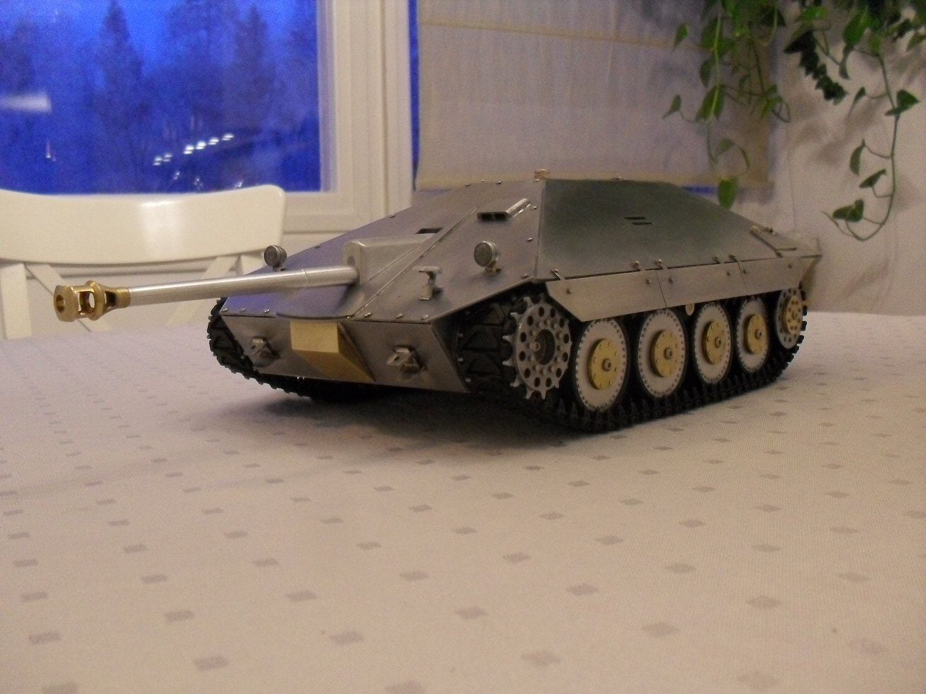
Finished this Maresal as far as I am concerned. Missing an antennae but any old HL one would do (thats the fitting I used).
Added the obligatory Stug III for size comparison. Which is appropriate given that it was against the Stug that the Maresal shone.
Reasonably happy with it. Some things I would have done differently or not at all. Now it joins a growing list of tanks needing paint and electronics!
P
01-31-2021, 12:12 PM
#47
Again, outstanding work.
I'd imagine laying the gun must have taken exceptional control at steering unless there is lateral (traverse / windage ) main gun control I can't see.
However with that low silhouette it would have been devilishly difficult to spot at range.
Jerry
I'd imagine laying the gun must have taken exceptional control at steering unless there is lateral (traverse / windage ) main gun control I can't see.
However with that low silhouette it would have been devilishly difficult to spot at range.
Jerry
01-31-2021, 12:19 PM
#48
Thread Starter
I wonder would the Romanians have fared any better on the Stalingrad flanks if they'd had a couple of hundred of these things?
Im guessing it was their experiences there and German reluctance to help them out that spurred interest in their own tank destroyers.....
p
Im guessing it was their experiences there and German reluctance to help them out that spurred interest in their own tank destroyers.....
p
01-31-2021, 03:11 PM
#49
That is so good. Totally impressed!