


Don Smith A-26 Build


 01-16-2016, 09:05 AM
#178

Thread Starter
Join Date: Nov 2005
Location: fort collins,
CO
Posts: 448
Likes: 0
Received 0 Likes
on
0 Posts
With half the flap being tucked under the wing, there's a lot of effort to get a good clean fit. The TE of the _wing_ above the flap must taper to a razor edge. Reinforce with fiberglass before shaping. Here's what it looks like.

Then the flap needs to be shaped to fit. I ended up adding an additional layer of 3/16" balsa to the top of the flap to get it to fit. Once the hinges are mounted the LE of the flap will get sanded to a rounded airfoil shape.


Then the flap needs to be shaped to fit. I ended up adding an additional layer of 3/16" balsa to the top of the flap to get it to fit. Once the hinges are mounted the LE of the flap will get sanded to a rounded airfoil shape.
01-24-2016, 12:24 PM
#179
Thread Starter
Join Date: Nov 2005
Location: fort collins,
CO
Posts: 448
Likes: 0
Received 0 Likes
on
0 Posts
I've changed the hinge a little. The approach will make a smaller hinge, less sticking out below the wing and simpler to build. Here's the hinge that will be used on all the flaps. Also you can see them mounted. Held in with screws at this point, so I can disassemble it all.


01-24-2016, 12:27 PM
#180
Thread Starter
Join Date: Nov 2005
Location: fort collins,
CO
Posts: 448
Likes: 0
Received 0 Likes
on
0 Posts
Flap servo mount same as the inner flaps.

Here's a view of the mounted flap open so you can see the ball link at the LE of the flap.

Here it is closed, good fit.

Here's a view of the mounted flap open so you can see the ball link at the LE of the flap.
Here it is closed, good fit.
02-06-2016, 04:44 PM
#181
Thread Starter
Join Date: Nov 2005
Location: fort collins,
CO
Posts: 448
Likes: 0
Received 0 Likes
on
0 Posts
Flap progress. Here's the complete linkage assembly. All 4 flaps will be set up the exact same way.

Flap setup now complete on left wing inner and outer flaps.


Flap setup now complete on left wing inner and outer flaps.
02-06-2016, 08:38 PM
#182
Thread Starter
Join Date: Nov 2005
Location: fort collins,
CO
Posts: 448
Likes: 0
Received 0 Likes
on
0 Posts
Nothing show motion like a video. This is the full travel of the servo, so "full down" at this point is a little extreme. Main thing I'm looking for here is that they both behave the same.
https://youtu.be/wWrBolNfV78
https://youtu.be/wWrBolNfV78
04-30-2016, 11:46 AM
#183
Thread Starter
Join Date: Nov 2005
Location: fort collins,
CO
Posts: 448
Likes: 0
Received 0 Likes
on
0 Posts
Well, it's been 2 months since I've had time to work on the -26. But getting back to it. After lots of internal debate on how to hold the wing outer panels on, I decided to go with brass tubes that run from the wing panel to the inside of the wheel well. Two tubes are required, one fitting inside the other. Then a cotter pin holds the brass tubes. Here's a couple of picts.


05-14-2016, 10:34 AM
#184
Thread Starter
Join Date: Nov 2005
Location: fort collins,
CO
Posts: 448
Likes: 0
Received 0 Likes
on
0 Posts
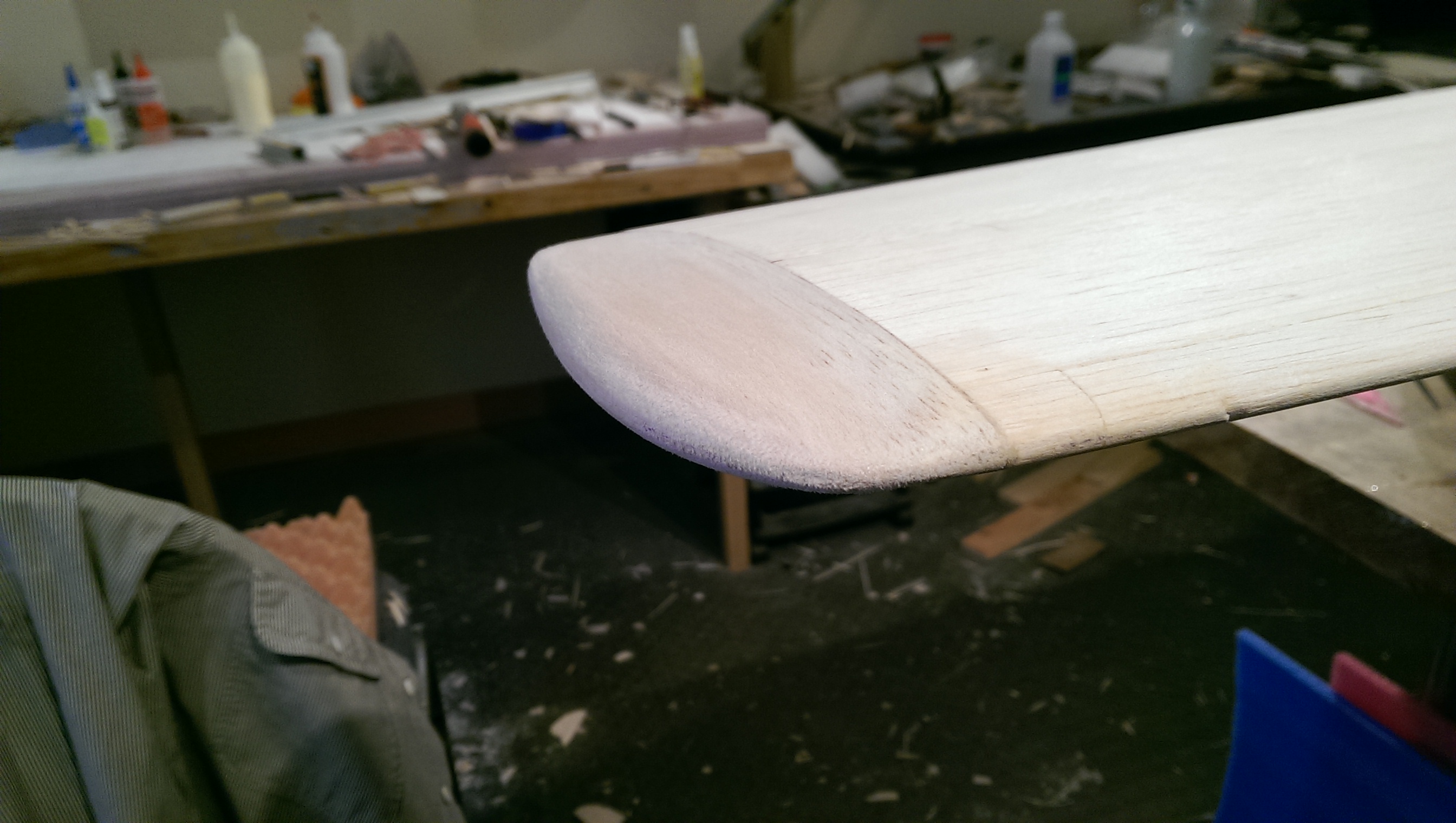
In the previous flap pictures you can see that the LE has not been shaped. On a basic flap, the LE can be square. However, on the slotted flap, the flap itself is a wing when deployed. Here's the final shape of the outer flap.


05-15-2016, 01:28 PM
#185
Thread Starter
Join Date: Nov 2005
Location: fort collins,
CO
Posts: 448
Likes: 0
Received 0 Likes
on
0 Posts
Using a Rotary Drive System to embed all aileron controls in the wing. Here's the setup of the right aileron.

If you're interested this is the system I installed.
http://www.geniebuild.com/g2_rds.html
If you're interested this is the system I installed.
http://www.geniebuild.com/g2_rds.html
07-17-2016, 09:16 AM
#186
Thread Starter
Join Date: Nov 2005
Location: fort collins,
CO
Posts: 448
Likes: 0
Received 0 Likes
on
0 Posts
Drilling out the nose gun mount locations. 8 holes needed to be perfectly aligned. The other A-26 builder came up with this jig. It worked perfectly to get all the holes aligned and have our 2 A-26 gun placements look identical.


08-06-2016, 03:11 PM
#187
Thread Starter
Join Date: Nov 2005
Location: fort collins,
CO
Posts: 448
Likes: 0
Received 0 Likes
on
0 Posts
OK, now at this point all the flaps and both ailerons have been sanded to the correct shape and fitted to the wing. Servo installation and access hatches are complete, so everything works and there is plenty of throw on all the control surfaces. Now I can close up the bottom of the wing ... finally. 


 09-05-2016, 11:56 AM
#189
Thread Starter
Join Date: Nov 2005
Location: fort collins,
CO
Posts: 448
Likes: 0
Received 0 Likes
on
0 Posts
Wing tips going on. Straight forward blocks cut to shape and sanded. The only thing to watch is the TE. Need the aileron set at the correct neutral position to get the final shape right.


10-28-2016, 06:58 PM
#190
Thread Starter
Join Date: Nov 2005
Location: fort collins,
CO
Posts: 448
Likes: 0
Received 0 Likes
on
0 Posts
With the outer wing panels complete, it's time to get back to the nacels. Finished framing them out.


Then it's on to that oh so fun job ... planking. Here's the left nacel almost completely planked.

Then it's on to that oh so fun job ... planking. Here's the left nacel almost completely planked.
10-30-2016, 01:08 PM
#191
Thread Starter
Join Date: Nov 2005
Location: fort collins,
CO
Posts: 448
Likes: 0
Received 0 Likes
on
0 Posts
After sanding out the nacelle I plotted locations for the gear doors and a hatch for accessing the tank, ign battery, & throttle servo. Once again, the plans are of little use here as door location and size is wrong.


The gear doors are made of fiberglass. The bottom of the nacelle is a template for the shape.

The gear doors are made of fiberglass. The bottom of the nacelle is a template for the shape.
11-23-2016, 11:15 AM
#192
Thread Starter
Join Date: Nov 2005
Location: fort collins,
CO
Posts: 448
Likes: 0
Received 0 Likes
on
0 Posts
Work on the 2nd nacelle has progressed to about the same stage as the 1st. Here laying up glass for the gear doors. Note you can see the outline of the doors through the glass. Even the writing on the nacelle is visible.

11-25-2016, 06:27 PM
#193
Thread Starter
Join Date: Nov 2005
Location: fort collins,
CO
Posts: 448
Likes: 0
Received 0 Likes
on
0 Posts
Here's the hatch that's been built. Once the area is cut out the hatch and nacelle have both been lined with balsa and ply. Used a dowel and screw to hold it all in place. This provides access to the tank, throttle servo, and ignition battery.
Showing the left side, but same approach for each.


Showing the left side, but same approach for each.
12-11-2016, 02:47 PM
#194
Thread Starter
Join Date: Nov 2005
Location: fort collins,
CO
Posts: 448
Likes: 0
Received 0 Likes
on
0 Posts
Planking the nacelle is in stages. I did the bottom first. Then the top. This ends up leaving areas in front and behind of the wing that get done separately. You can also see that I've left an open area near the back end of the nacelle. Here the planks have to twist a lot. so it's easier to do in 2 separate parts. The cone on the back of the nacelle is made from balsa blocks and sanded to shape.


12-12-2016, 06:01 PM
#196
Senior Member
My Feedback: (9)
Join Date: Jan 2003
Location: Phoenix, AZ
Posts: 166
Likes: 0
Received 0 Likes
on
0 Posts
love it - I am going to look at that roto drive setup for my P-39. Do you think there was too much slop in the orginal build or were you simply trying to hide the control horn and arms?
12-16-2016, 12:55 PM
#197
Thread Starter
Join Date: Nov 2005
Location: fort collins,
CO
Posts: 448
Likes: 0
Received 0 Likes
on
0 Posts
Wanted to hide the control arms. That's the main driver, my first time using them. I am impressed with how easy it was to set up and they have no slop. Great system.
01-16-2017, 07:44 PM
#198
Thread Starter
Join Date: Nov 2005
Location: fort collins,
CO
Posts: 448
Likes: 0
Received 0 Likes
on
0 Posts
Finished all the planking (oh, thank God!). Most of the sanding is done too.

Next I am cutting in the recessed areas for the exhausts. These are significant features on the A-26. Here's a shot of the side nacelle of a full scale A-26.

Next I am cutting in the recessed areas for the exhausts. These are significant features on the A-26. Here's a shot of the side nacelle of a full scale A-26.
01-16-2017, 07:47 PM
#199
Thread Starter
Join Date: Nov 2005
Location: fort collins,
CO
Posts: 448
Likes: 0
Received 0 Likes
on
0 Posts
The cut outs are not all the same size when you look all around the nacelle. Made a simple paper template you can see sitting on the top of the wing.

And here's the left nacelle exhaust cut outs, all sanded to shape.


And here's the left nacelle exhaust cut outs, all sanded to shape.