


Top RC Zero from Gator R/C
 12-22-2015, 11:09 PM
#76

My Feedback: (5)
Join Date: Jan 2010
Location: vancouver, BC, CANADA
Posts: 131
Likes: 0
Received 0 Likes
on
0 Posts
gents need some help on the mounting of the engine. that being the evolution 777 never mounted a radial before and it seems that the motor box on the plane may be a bit to small the engine has two sets of holes the outer is not taped but the inner is threaded still if i will use the inner diameter holes they come very close to the edge of the mounting box any help would be great maybe a few pics thanks in advance
 12-23-2015, 06:21 AM
#77

Starting on the fuse. I did some pre-work on the tail wheel in prep of the install. I noticed the opening is fairly narrow, so I spaced my tail wheel as narrow as I could and used some narrower nuts. The axle is fairly long, but I spaced it so that I could tighten the nuts and locktite them instead of using the wide ny-lock nuts. Then I ground off the excess axle. Seems like it will fit into the opening now.

I didn't like the way the rudder actuator went into some plywood, then is glued down deep into the tail. I decided to create a bit better bearing for the rod. I used a piece of brass tube that fit tight around the rod, combined with a washer on each end. I glued it all together with some Hysol. This should make it more durable and less likely that I'll have to rip it out to replace the wood anytime soon. Initial fitting would indicate it will fit in well and do the job.

I mounted the rudder servo. The plywood mount was kind of thin, so I added some wood underneath to give the screws a bit more purchase. Other than that it seems up to the task. I oriented the servo horn towards the rear, where the mount was the strongest.

I have a lot of time off over the holiday, so my plan is to get plenty of time on the Zero and get it finished. Stay tuned for a faster pace as I finish up the fuse and get it done. I plan on doing a lot of scale detailing after the build, and wouldn't be surprised if I spend more time on that than the functional stuff. I'll be making some mods to the cockpit, adding a scale radial engine, adding guns, along with the new paint scheme and a bunch of surface detailing.
I didn't like the way the rudder actuator went into some plywood, then is glued down deep into the tail. I decided to create a bit better bearing for the rod. I used a piece of brass tube that fit tight around the rod, combined with a washer on each end. I glued it all together with some Hysol. This should make it more durable and less likely that I'll have to rip it out to replace the wood anytime soon. Initial fitting would indicate it will fit in well and do the job.
I mounted the rudder servo. The plywood mount was kind of thin, so I added some wood underneath to give the screws a bit more purchase. Other than that it seems up to the task. I oriented the servo horn towards the rear, where the mount was the strongest.
I have a lot of time off over the holiday, so my plan is to get plenty of time on the Zero and get it finished. Stay tuned for a faster pace as I finish up the fuse and get it done. I plan on doing a lot of scale detailing after the build, and wouldn't be surprised if I spend more time on that than the functional stuff. I'll be making some mods to the cockpit, adding a scale radial engine, adding guns, along with the new paint scheme and a bunch of surface detailing.
12-24-2015, 08:03 AM
#79
Time to get the tail done. I started by looking at the cable routing for the pull-pull. I noticed that some of the holes were blocked by glue, so I had to get a bit down in there and clear them out. The deep holes for the rudder were not easy to get to. Once cleared, there was a benefit to the glue, it helped to make the hole a bit stronger and less apt to wear from the cable.

Prior to installing the rudder control arm, I had to get the cables mounted. Once glued in it would be almost impossible to get to them. I used the stock cable and crimp connectors. The crimp barrel was a bit large, but that allowed me to wrap the wire around from each direction to make sure it never comes loose. Here it is crimped on and ready to put into the tail.

I slid it into position and test fitted the rudder. Everything seemed fine.

Looking at the tail wheel mount I decided to add some glue and balsa to strengthen it since the upper mount will take the load if you drop the plane on it's tailwheel. It should help with minimal weight. I then hinged the rudder (same as shown for other surfaces earlier) and glued it into place. I had to drill out the hole a bit for the control arm and I sanded the arm to help glue adhesion. Then I installed the bearing using hysol.
Here's a photo showing the extra mount reinforcement and the rudder control arm bearing installed.

Rudder seemed to move freely and I'm happy with the way it all turned out.
Prior to installing the rudder control arm, I had to get the cables mounted. Once glued in it would be almost impossible to get to them. I used the stock cable and crimp connectors. The crimp barrel was a bit large, but that allowed me to wrap the wire around from each direction to make sure it never comes loose. Here it is crimped on and ready to put into the tail.
I slid it into position and test fitted the rudder. Everything seemed fine.
Looking at the tail wheel mount I decided to add some glue and balsa to strengthen it since the upper mount will take the load if you drop the plane on it's tailwheel. It should help with minimal weight. I then hinged the rudder (same as shown for other surfaces earlier) and glued it into place. I had to drill out the hole a bit for the control arm and I sanded the arm to help glue adhesion. Then I installed the bearing using hysol.
Here's a photo showing the extra mount reinforcement and the rudder control arm bearing installed.
Rudder seemed to move freely and I'm happy with the way it all turned out.
12-24-2015, 08:22 AM
#80
Before mounting the tailwheel I decided to mount the horiz. stabs so I could run the wires without the tailwheel in the way. earlier investigation had determined that there is some wood in the carbon fiber tubes to help the screws hold. The wood is not very wide though, so you have to make sure you hit it. I found that the tubes could move a bit farther each way than center. If you don't center the tubes you could miss the wood inside. I centered the tubes on the fuse, and used a touch of glue to hold them in place. I'm not taking it all apart, I only need the stabs removable to get to the servos. Tacking them into place has the additional benefit of making it easy to align the screws if you take it apart.

I verified that the holes would hit the wood inside the tubes and drilled the chase holes for the mount screws. Instead of the stock screws, I used some others I had so I didn't need separate washers. The screws went in tight and I'm very happy with the mounting system. I'll paint the heads of the screws later.

Now to mount the tailwheel assy. First I checked out the cable routing. In this case the cables have to go wide to catch the routing holes. To minimize friction I added some plastic tubes into the holes where the pull pull cables would run.

After test fitting the tailwheel and removing any glue/burrs etc. I was ready to mount it. I put it into place using the lower screws first, then marked the upper mounts for drilling. I had to use my dremmel with skinny drill attachment to get down into the tail.

I had some wood screws that had the same head, but were a bit longer than that provided. I routed the cable and servo lead down the fuse, then mounted the tailwheel. There's not a lot of room, so you really need to get it centered correctly.

Using a dremmel with sanding drum I made sure the tailwheel would cycle without hitting. Then I test fitted the cover and sanded away the extra on it as well. I mounted the cover with some screws, some of which had to be shortened to make sure they wouldn't interfere with the movement of the tailwheel.


I'm happy with the way it turned out. Hopefully it stays tight, since there's not a lot of extra space for it to retract properly.
I got the servo wires and pull pull wires sorted out in preparation for the next step, mounting the ends of the pull pull system. I used some ties to keep the servo leads in place. I used a twist tie down deep in the fuse since it's easy to reach in and remove it if I have to.

More to come soon.
I verified that the holes would hit the wood inside the tubes and drilled the chase holes for the mount screws. Instead of the stock screws, I used some others I had so I didn't need separate washers. The screws went in tight and I'm very happy with the mounting system. I'll paint the heads of the screws later.
Now to mount the tailwheel assy. First I checked out the cable routing. In this case the cables have to go wide to catch the routing holes. To minimize friction I added some plastic tubes into the holes where the pull pull cables would run.
After test fitting the tailwheel and removing any glue/burrs etc. I was ready to mount it. I put it into place using the lower screws first, then marked the upper mounts for drilling. I had to use my dremmel with skinny drill attachment to get down into the tail.
I had some wood screws that had the same head, but were a bit longer than that provided. I routed the cable and servo lead down the fuse, then mounted the tailwheel. There's not a lot of room, so you really need to get it centered correctly.
Using a dremmel with sanding drum I made sure the tailwheel would cycle without hitting. Then I test fitted the cover and sanded away the extra on it as well. I mounted the cover with some screws, some of which had to be shortened to make sure they wouldn't interfere with the movement of the tailwheel.
I'm happy with the way it turned out. Hopefully it stays tight, since there's not a lot of extra space for it to retract properly.
I got the servo wires and pull pull wires sorted out in preparation for the next step, mounting the ends of the pull pull system. I used some ties to keep the servo leads in place. I used a twist tie down deep in the fuse since it's easy to reach in and remove it if I have to.
More to come soon.
12-26-2015, 11:40 AM
#81
Continuing on, I needed to get the pull-pull hooked up. I took my time, since it would be difficult to undo the cables on the tail wheel if I screw it up. First I aligned the wires into my servo horn to see where they would run through the fuse. According to the instructions, there's a wood piece that goes across to guide the wires. I didn't get it, but looking at in in the instruction photos I wouldn't have used it. It does not align the cables in a natural way. I made my own guide by marking the cable positions and putting a piece of light ply across the fuse. Here's what it looks like once done.

I worked very patiently to hook up the cables, making sure I got them as accurate as possible so I'd have some adjustment if needed. The stock linkage seemed acceptable, so that's what I used. The throw on the servo horn is a bit more than the throws on the tail end, but it's pretty close and seemed to work fine. It would be nice if the rudder had a bit wider horns on back, but it's space limited. You'll need the cables to be fairly tight to maintain a tight rudder.

I tested the rudder and tailwheel movement with my servo tester, and I'm pretty happy with it.
I worked very patiently to hook up the cables, making sure I got them as accurate as possible so I'd have some adjustment if needed. The stock linkage seemed acceptable, so that's what I used. The throw on the servo horn is a bit more than the throws on the tail end, but it's pretty close and seemed to work fine. It would be nice if the rudder had a bit wider horns on back, but it's space limited. You'll need the cables to be fairly tight to maintain a tight rudder.
I tested the rudder and tailwheel movement with my servo tester, and I'm pretty happy with it.
12-26-2015, 11:50 AM
#82
Time to move to the front end. I will be installing a EME-70 twin. It looks like a nice engine, hopefully it runs as good as it looks.

The length of the engine is about right according to the instructions if I use the small stand offs that come with it. I picked up some 10-24 allen bolts and blind nuts from the hardware store. The EME comes with a nice template. I stuck it on the firewall and it gave me the hole location perfectly. About as easy as it gets.

I drilled the holes for the engine mounts. I noticed the stand offs would hit the angle wood, so I used the flat end of my dremmel grinder wheel to clear the area so the mounts would sit flush.

Engine mounting was uneventful. Here's the engine bolted on to the firewall for the first time.

Instructions show some sort of template for the scale exhaust and cowl mount. I was missing that, so I pushed ahead aligning everything myself. The cowl mount lines up well with the outside of the fuse. After putting the cowl on and off a couple of times I went ahead and mounted the cowl ring. I used the screws provided with washers.

I took it back off and ground the firewall flush, and removed paint where it hit. I used some Zap Goo to aid in keeping it in place (with the screws). I holds well, but is removable if I have to. There was some glass that interfered, so I wouldn't skip the grinding step.

The length of the engine is about right according to the instructions if I use the small stand offs that come with it. I picked up some 10-24 allen bolts and blind nuts from the hardware store. The EME comes with a nice template. I stuck it on the firewall and it gave me the hole location perfectly. About as easy as it gets.
I drilled the holes for the engine mounts. I noticed the stand offs would hit the angle wood, so I used the flat end of my dremmel grinder wheel to clear the area so the mounts would sit flush.
Engine mounting was uneventful. Here's the engine bolted on to the firewall for the first time.
Instructions show some sort of template for the scale exhaust and cowl mount. I was missing that, so I pushed ahead aligning everything myself. The cowl mount lines up well with the outside of the fuse. After putting the cowl on and off a couple of times I went ahead and mounted the cowl ring. I used the screws provided with washers.
I took it back off and ground the firewall flush, and removed paint where it hit. I used some Zap Goo to aid in keeping it in place (with the screws). I holds well, but is removable if I have to. There was some glass that interfered, so I wouldn't skip the grinding step.
12-26-2015, 12:04 PM
#83
Before finishing the cowl mounting I decided to take a little detour and visit the scale exhausts. I checked and verified that they could be mounted after the cowl ring. I knew they needed some work to look more realistic. The exhausts are a big part of the Model 52 Zero, so they couldn't be some sort of round pipe in my book.
First I heated them up and flattened them a bit. This can be done with a pliers, or hammer. They are stout, so prepare for some work.Once flattened to shape I put them on the fuse to see how they looked. They still stuck out in a weird way, so I knew I needed to get some shape added.

I used the handle from a spanner wrench that would fit inside the exhaust. By working my way from the inside out and doing some hammering I was able to get an acceptable shape.

Here's a photo showing the comparison and the way they looked after shaping.


After a bit of sanding and flaring of the outlets I decided I needed the final scale touch. Using some JB weld I added the "weld" that goes through the center of each pipe. I used a toothpick to make an accurate "bead."

I did a basic rust color spray on the exhausts before mounting. I'll add a more realistic look to them during the detailing steps. Here's a close up of one of the finished exhausts. The two top ones should have a downward curve, but I was unable to get that to happen. The'll have to be good enough.

Next I mounted the cowl. I initially had it pretty far forward, be re-thought it and moved it back some. I flared out the back of the cowl a bit to help cooling.

I found a nice way to add a choke rod. I made a guide for the rod, and it will come out behind the cowl on the bottom. The means I don't have to add a choke servo.

That's it for now, much more to come.
First I heated them up and flattened them a bit. This can be done with a pliers, or hammer. They are stout, so prepare for some work.Once flattened to shape I put them on the fuse to see how they looked. They still stuck out in a weird way, so I knew I needed to get some shape added.
I used the handle from a spanner wrench that would fit inside the exhaust. By working my way from the inside out and doing some hammering I was able to get an acceptable shape.
Here's a photo showing the comparison and the way they looked after shaping.
After a bit of sanding and flaring of the outlets I decided I needed the final scale touch. Using some JB weld I added the "weld" that goes through the center of each pipe. I used a toothpick to make an accurate "bead."
I did a basic rust color spray on the exhausts before mounting. I'll add a more realistic look to them during the detailing steps. Here's a close up of one of the finished exhausts. The two top ones should have a downward curve, but I was unable to get that to happen. The'll have to be good enough.
Next I mounted the cowl. I initially had it pretty far forward, be re-thought it and moved it back some. I flared out the back of the cowl a bit to help cooling.
I found a nice way to add a choke rod. I made a guide for the rod, and it will come out behind the cowl on the bottom. The means I don't have to add a choke servo.
That's it for now, much more to come.
12-26-2015, 05:22 PM
#84
My Feedback: (5)
Join Date: Jan 2010
Location: vancouver, BC, CANADA
Posts: 131
Likes: 0
Received 0 Likes
on
0 Posts
Does anybody have an extra control board for the electric retracts pluged mine in and went up in smoke dont really know what happened may have been faaulty or i may have reversed a frikin wire anyway please let me know if someone has an extra i can buy regards
12-27-2015, 06:51 AM
#85

My Feedback: (26)
Join Date: Apr 2002
Location: Dimondale,
MI
Posts: 53
Likes: 0
Received 0 Likes
on
0 Posts
I have a set of retracts for the Zero in the box no struts or wheels, just retracts and controller. [email protected]
12-27-2015, 06:54 PM
#87
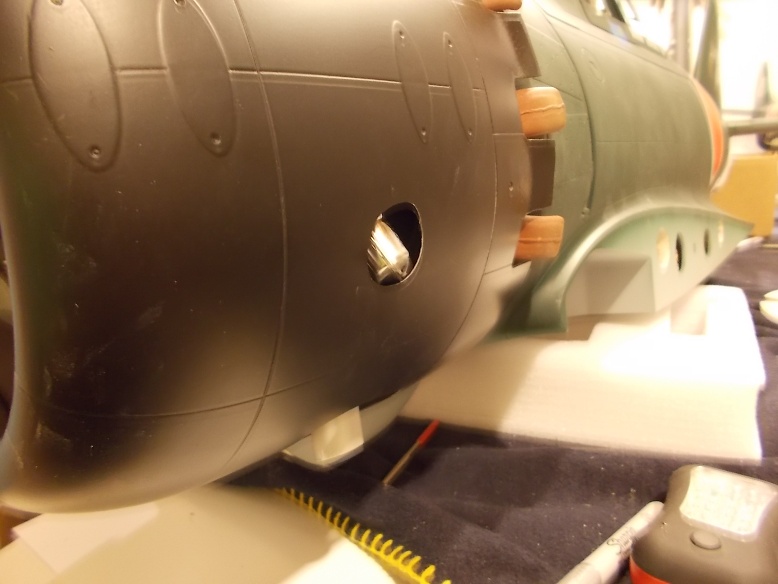
Now that the cowl is mounted I can finish up some details. I made a plywood plate to create a baffle to help with cooling. The Top Flite Zero dummy radial will fit fine even though it's a tad small. The wood backing plate is too small as well, but that's OK since I need it to do more than just mount the dummy engine. Here's a photo showing my initial cutting.

Before doing the final fitting on the dummy engine I decided to get the exhaust mounted. I cut down the pipes a bit, then made some holes in the cowl. I made the holes a bit bigger than needed to ease cowl installation and add a bit of air outlet. I ended up cutting down the stacks a bit more later to make it even easier to get the cowl on after the dummy engine is installed.

The plug caps are a bit wide for the cowl. so I had to make some clearance holes. They also have to be a little bit bigger than needed to allow the cowl to be installed. They ended up not too obnoxious, and with a bit of flat black on the plug caps they wont be very noticeable. Some may opt for the tiny plug conversion, but I didn't want to risk performance (I'm not familiar with how those plugs perform).
I spent a bit more time on the dummy radial than originally planned, but in the end it looks good. As mentioned, it's a bit farther forward than stock, but I'd say my spinner sits out more forward than the real thing as well. I think the dummy engine adds a lot to the appearance. I have a little trimming to do to the front of the engine, but will do that after the glue dries. Here's how it looks.

I'm off all week, so I plan to get a bunch more done soon.
Before doing the final fitting on the dummy engine I decided to get the exhaust mounted. I cut down the pipes a bit, then made some holes in the cowl. I made the holes a bit bigger than needed to ease cowl installation and add a bit of air outlet. I ended up cutting down the stacks a bit more later to make it even easier to get the cowl on after the dummy engine is installed.
The plug caps are a bit wide for the cowl. so I had to make some clearance holes. They also have to be a little bit bigger than needed to allow the cowl to be installed. They ended up not too obnoxious, and with a bit of flat black on the plug caps they wont be very noticeable. Some may opt for the tiny plug conversion, but I didn't want to risk performance (I'm not familiar with how those plugs perform).
I spent a bit more time on the dummy radial than originally planned, but in the end it looks good. As mentioned, it's a bit farther forward than stock, but I'd say my spinner sits out more forward than the real thing as well. I think the dummy engine adds a lot to the appearance. I have a little trimming to do to the front of the engine, but will do that after the glue dries. Here's how it looks.
I'm off all week, so I plan to get a bunch more done soon.
12-31-2015, 12:41 PM
#88
For my throttle linkage I used a aluminum ball link and Ny-rod. The instructions didn't give any guidance for the throttle servo location, so I found a spot clear of the tank that had a nice straight shot for the EME-70.
Here's the ball link on the throttle arm.

Here's a shot showing the servo mounting location. I'm not sure I'll trust this tactic servo, but it was the right size to get the mount right.

I mounted two servos in the spots provided for the clamshell doors. I decided to create a panel for the twin receiver batteries. This allows me to have a charge jack and shut off both batteries so the Smart Fly module I'm using doesn't drain them. The panel was made from a piece of carbon fiber I had laying around. Dual switch with fuel dot was from Tower Hobbies.

I had a get together at my house, so I thought I'd use the opportunity to put it on the gear for the first time to see how it looks. Here it is in my basement, large and in charge.

Here's the ball link on the throttle arm.
Here's a shot showing the servo mounting location. I'm not sure I'll trust this tactic servo, but it was the right size to get the mount right.
I mounted two servos in the spots provided for the clamshell doors. I decided to create a panel for the twin receiver batteries. This allows me to have a charge jack and shut off both batteries so the Smart Fly module I'm using doesn't drain them. The panel was made from a piece of carbon fiber I had laying around. Dual switch with fuel dot was from Tower Hobbies.
I had a get together at my house, so I thought I'd use the opportunity to put it on the gear for the first time to see how it looks. Here it is in my basement, large and in charge.
12-31-2015, 12:59 PM
#89
I did some mounting of the other switches and receiver. Because of the size of the Smart fly module I had to mount the receiver down out of the way (and a bit more to the rear than I would have liked). I had to keep most of that tray clear or it would interfere with the front floor of the scale cockpit. For switches I have the two for the main receiver batteries mounted on the panel shown earlier, and one on the front floor for the ignition battery and charge. One more switch goes to the smart fly module, and that's mounted to allow it to be switched from outside. If you hit that switch it turns the receiver and ignition off.
Photo showing initial receiver position and wiring. Note that you also want to keep clear the area where you access the drop tank screws, and have enough space to tuck in the wing connections.

Notice here the black line designating the area that should be kept clear for the cockpit. The two switches can be seen on the right, as well as the retract circuit board mounted to the right side of the fuse.

For the wing connections I used 9 pin Ashlock connectors. Used often on jets, I normally get them from Dreamworks. They make excellent snap in connections if you have a crimp tool to put them together.

Here's the main switch outside the plane. I kind of hid it inside the scale detail, which also had more strength. I was able to tie strap it on the inside as well.

Mounting the ignition box was straight forward. I screwed down a velcro strap and put some foam under it. The plug wires routed fine from there, and a quick hole in the firewall allows the wiring to meet up with the smart fly fiber optic kill switch. I'll tie strap everything once I get the fuel lines ran.

Not much left. I have to get the fuel system installed and final battery placement. I also will need to figure out what I'll do about the clamshell doors. I can't use my radio to do a delay, since 4 seconds is not enough (the gear takes over 8 seconds to retract). I could get a sequencer if I decide to use the two servos to actuate the doors. I'd prefer a mechanical set up if it works nice. I know someone earlier mentioned making some parts for that, so I have to decide if I want to wait or go ahead and make it electric.
Photo showing initial receiver position and wiring. Note that you also want to keep clear the area where you access the drop tank screws, and have enough space to tuck in the wing connections.
Notice here the black line designating the area that should be kept clear for the cockpit. The two switches can be seen on the right, as well as the retract circuit board mounted to the right side of the fuse.
For the wing connections I used 9 pin Ashlock connectors. Used often on jets, I normally get them from Dreamworks. They make excellent snap in connections if you have a crimp tool to put them together.
Here's the main switch outside the plane. I kind of hid it inside the scale detail, which also had more strength. I was able to tie strap it on the inside as well.
Mounting the ignition box was straight forward. I screwed down a velcro strap and put some foam under it. The plug wires routed fine from there, and a quick hole in the firewall allows the wiring to meet up with the smart fly fiber optic kill switch. I'll tie strap everything once I get the fuel lines ran.
Not much left. I have to get the fuel system installed and final battery placement. I also will need to figure out what I'll do about the clamshell doors. I can't use my radio to do a delay, since 4 seconds is not enough (the gear takes over 8 seconds to retract). I could get a sequencer if I decide to use the two servos to actuate the doors. I'd prefer a mechanical set up if it works nice. I know someone earlier mentioned making some parts for that, so I have to decide if I want to wait or go ahead and make it electric.
01-02-2016, 06:50 AM
#91
My Feedback: (5)
Join Date: Jan 2010
Location: vancouver, BC, CANADA
Posts: 131
Likes: 0
Received 0 Likes
on
0 Posts
i would not recomend using a lipo without a regulator as i found out the board cant take the voltage . even though they claim it can handle 7,4 volts mine when up in smoke after a few dozen cycles i talked to thomas at vq warbirds where i did buy the model and he told me that the company is going to send him new and improved controll boards in the next few weeks and that for now i should run a regulator at 6 volts hope this helps / hot rod have u balanced your plane yet ? if so how much weight did you need up front i put in an evo 7 cylinder wich is quite heavy with ignition and kelo exhaust would like to no if i should place all 4 batts up front
01-02-2016, 10:23 AM
#93

While HotRodTodd has given a great build guide , I thought I would add a little.
The cockpit is made of ABS plastic and would hold up for a while as is. I plan on adding some detail to mine to improve the looks and adding a 1/5 pilot as well.

 So thing that needs to be done to ensure years of service. I have planes still flying after being built 20yrs ago. I took the cockpit and poped it off of the frame work and CA'ed some 1/16 balsa planking to the sides all the way around it. Then I added some 6oz cloth wicked with epoxy around the entire tub. That will make it last for years to come. The full blown cockpit will add about 1lb, but that is fine it will need the nose weight.
The cockpit is made of ABS plastic and would hold up for a while as is. I plan on adding some detail to mine to improve the looks and adding a 1/5 pilot as well.
01-02-2016, 03:34 PM
#94
To answer some questions: I didn't do the balance test yet. I'm at that point, just haven't done it yet. It's a Zero, nose weight will be needed I'm sure. Most likely I'll bolt some metal to the engine box. No matter what engine you're using, the batteries will need to go up front. I stuck mine in the space around the fuel tank.
I am using 6.6V LiFe packs (two rcv and one ignition). Since I have two 2500 mah on the receiver I was planning on just using receiver power on the retracts. Only issue with that is if the board goes up in smoke, it could kill my receiver power. A better option may be to use the ignition battery.
I heard about the replacement boards. From what I heard, it's not due to them burning up at higher voltage, but because they sometimes get mixed up on where they should be. In other words, you turn on your plane with the gear down, and next thing you know the mains go up and the tailwheel is down. It happened to me once while I was testing, so I know it's an issue on my board. Mike at Gator RC also mentioned that all boards would be replaced to correct the issue. I did notice a warning in the manual about repeated back to back cycles could overheat the board.
TimD, I agree that some extra strength could help the cockpit. It's a tight fit between the ribs, so I'm wondering if you'll have to make some adjustments after adding the wood to get it to slide back in. Gasser vibration will break that stiff plastic apart after time. Most likely I'll keep mine light and fix it if it cracks. As for a pilot, I'm hoping my buddy will stop over with his best pilots Subaro Sakai so I can see if he'll work.
01-03-2016, 06:26 AM
#95
My Feedback: (13)
To answer some questions: I didn't do the balance test yet. I'm at that point, just haven't done it yet. It's a Zero, nose weight will be needed I'm sure. Most likely I'll bolt some metal to the engine box. No matter what engine you're using, the batteries will need to go up front. I stuck mine in the space around the fuel tank.
I am using 6.6V LiFe packs (two rcv and one ignition). Since I have two 2500 mah on the receiver I was planning on just using receiver power on the retracts. Only issue with that is if the board goes up in smoke, it could kill my receiver power. A better option may be to use the ignition battery.
I heard about the replacement boards. From what I heard, it's not due to them burning up at higher voltage, but because they sometimes get mixed up on where they should be. In other words, you turn on your plane with the gear down, and next thing you know the mains go up and the tailwheel is down. It happened to me once while I was testing, so I know it's an issue on my board. Mike at Gator RC also mentioned that all boards would be replaced to correct the issue. I did notice a warning in the manual about repeated back to back cycles could overheat the board.
TimD, I agree that some extra strength could help the cockpit. It's a tight fit between the ribs, so I'm wondering if you'll have to make some adjustments after adding the wood to get it to slide back in. Gasser vibration will break that stiff plastic apart after time. Most likely I'll keep mine light and fix it if it cracks. As for a pilot, I'm hoping my buddy will stop over with his best pilots Subaro Sakai so I can see if he'll work.
I am using 6.6V LiFe packs (two rcv and one ignition). Since I have two 2500 mah on the receiver I was planning on just using receiver power on the retracts. Only issue with that is if the board goes up in smoke, it could kill my receiver power. A better option may be to use the ignition battery.
I heard about the replacement boards. From what I heard, it's not due to them burning up at higher voltage, but because they sometimes get mixed up on where they should be. In other words, you turn on your plane with the gear down, and next thing you know the mains go up and the tailwheel is down. It happened to me once while I was testing, so I know it's an issue on my board. Mike at Gator RC also mentioned that all boards would be replaced to correct the issue. I did notice a warning in the manual about repeated back to back cycles could overheat the board.
TimD, I agree that some extra strength could help the cockpit. It's a tight fit between the ribs, so I'm wondering if you'll have to make some adjustments after adding the wood to get it to slide back in. Gasser vibration will break that stiff plastic apart after time. Most likely I'll keep mine light and fix it if it cracks. As for a pilot, I'm hoping my buddy will stop over with his best pilots Subaro Sakai so I can see if he'll work.
01-03-2016, 08:26 AM
#96
Join Date: Aug 2006
Location: Austin, TX
Posts: 6
Likes: 0
Received 0 Likes
on
0 Posts
Thanks Hot Rod! I have a 3200 mah for the receiver and ignition (IBEC), and a 2100 mah for the gear. Both LiFe. Are you using a separate battery for the starter? I was thinking about either a two or three cell LiPo for that.
I'll talk with Mike about the retract controller board.
I'll talk with Mike about the retract controller board.
01-03-2016, 09:29 AM
#97
I don't have the electric start option. I kind of like hand flipping the big gasser's.
I prefer air retracts, but none were available. Don't be surprised if a deal with Robart doesn't make air an option in the future.
I got my fuel tank installed. I opted for a 27 oz. tank from Ideal available from mile high RC. Install wasn't too tough, there's plenty of room for whatever tank you decide. I used some velcro to hold down the back and made a mount to hold it in place. Foam all around should help with vibration.

One nice feature, I can easily look in the cockpit by the pilots feet and see how much fuel is left in the tank. Notice I cut just a bit out of the front of the cockpit floor for clearance.

Because the rear of the EME-70 has a rotating shaft, I had to make sure the fuel line would not rub against it. I made an aluminum plate that should keep it from touching, yet allow the line to turn without kinking.

I painted a 23x10 Zoar prop in brown primer, a close match for the model 52 Zero props. Some yellow on the tips completed the scale look. I balanced the backplate for the spinner. It took quite a bit of drilling to get it balanced, so I wouldn't skip doing it. I mounted it all up, so I'll be ready to check the balance of the plane to see how much weight I'll be needing.

I couldn't get my friends Sakai (I velcro my pilot's in, he used glue), so I pulled a best Pilots Gunther out of one of my 190's. According to the best pilots site, the Gunther is 3/4" shorter butt to head top, so I think the Sakai will look just fine in the cockpit. In these photos Gunther is propped up a bit, but they always seem to need something under the butt to line up correctly.


I'd keep the cockpit light, the CG hits at about the front of the canopy. Any weight in the cockpit will require even more nose weight to balance. Left to go, I have to get the clamshell doors mounted, then I can start the cockpit and detailing.
Here's a photo of the Best Pilots Sakai figure, excellent quality and detail yet very light.

I prefer air retracts, but none were available. Don't be surprised if a deal with Robart doesn't make air an option in the future.
I got my fuel tank installed. I opted for a 27 oz. tank from Ideal available from mile high RC. Install wasn't too tough, there's plenty of room for whatever tank you decide. I used some velcro to hold down the back and made a mount to hold it in place. Foam all around should help with vibration.
One nice feature, I can easily look in the cockpit by the pilots feet and see how much fuel is left in the tank. Notice I cut just a bit out of the front of the cockpit floor for clearance.
Because the rear of the EME-70 has a rotating shaft, I had to make sure the fuel line would not rub against it. I made an aluminum plate that should keep it from touching, yet allow the line to turn without kinking.
I painted a 23x10 Zoar prop in brown primer, a close match for the model 52 Zero props. Some yellow on the tips completed the scale look. I balanced the backplate for the spinner. It took quite a bit of drilling to get it balanced, so I wouldn't skip doing it. I mounted it all up, so I'll be ready to check the balance of the plane to see how much weight I'll be needing.
I couldn't get my friends Sakai (I velcro my pilot's in, he used glue), so I pulled a best Pilots Gunther out of one of my 190's. According to the best pilots site, the Gunther is 3/4" shorter butt to head top, so I think the Sakai will look just fine in the cockpit. In these photos Gunther is propped up a bit, but they always seem to need something under the butt to line up correctly.
I'd keep the cockpit light, the CG hits at about the front of the canopy. Any weight in the cockpit will require even more nose weight to balance. Left to go, I have to get the clamshell doors mounted, then I can start the cockpit and detailing.
Here's a photo of the Best Pilots Sakai figure, excellent quality and detail yet very light.
Last edited by Hot Rod Todd; 01-03-2016 at 09:40 AM.
01-03-2016, 12:08 PM
#98
So I put the Zero together to do some initial weights and balances. I threw my Best Pilot's Gunther into the cockpit and weighed it all up. Keep in mind there's some things left to go. I need to put the canopy glass in, detail the cockpit, sliding canopy rails, Clamshell doors. Not much weight wise.
All up weight is 24.6 lbs. I knew it was light, but that surprised me.
Checked the balance, and it was tail heavy as expected. To get it balanced as it sits it would take 2.75 lbs. if the weight is on the motor box. That would make the all up weight 27.35 lbs, still very light for a warbird with 1452 sq. in. of wing area.
After the scale details and cockpit mods I'll likely need 3 lbs of weight. It's a good thing it has split flaps, otherwise this thing would be a floater that could be tough to land. As it is it should be a very easy flier. I might make some battery changes since I need weight in the front anyway.
Here she is sitting on the wheels in my basement after revealing that she really does have a slim waistline.
01-03-2016, 03:30 PM
#100
My Feedback: (5)
Join Date: Jan 2010
Location: vancouver, BC, CANADA
Posts: 131
Likes: 0
Received 0 Likes
on
0 Posts
quick question i have my radial mounted onto the plane and while staring at how good that radial looks i just now realized this plane has quite a bit of down thrust are you guys noticing also may be normal but looks quite a bit to me