


TOPRC/GatorRC P-51 Mustang 89"
 06-28-2017, 02:17 AM
#326

My Feedback: (66)
Cast resin fuel caps available for those who may be interested. I've got them in most of the popular scales.
Attachment 2221872
Attachment 2221872
I would like to buy a few in 1/5 scale, please. What is the cost?
 06-28-2017, 11:43 AM
#327

My Feedback: (60)
Join Date: Dec 2001
Location: Litchfield Park,
AZ
Posts: 7,677
Likes: 0
Received 25 Likes
on
23 Posts
Just a few bucks each depending upon whether you want them raw or finished and painted. Shoot me an email N99JH and we can discuss the details. [email protected]
07-02-2017, 02:30 PM
#329
Question for those running the Top RC landing gear.
1. What servo are you running in the tail? Wondering if an 80 oz/in mini would be enough?
2. Did you have to modify the stock ball link locations on the tail gear doors to get it to function correctly?
Thanks
1. What servo are you running in the tail? Wondering if an 80 oz/in mini would be enough?
2. Did you have to modify the stock ball link locations on the tail gear doors to get it to function correctly?
Thanks
Last edited by Cpig; 07-02-2017 at 04:50 PM.
07-03-2017, 03:27 PM
#330
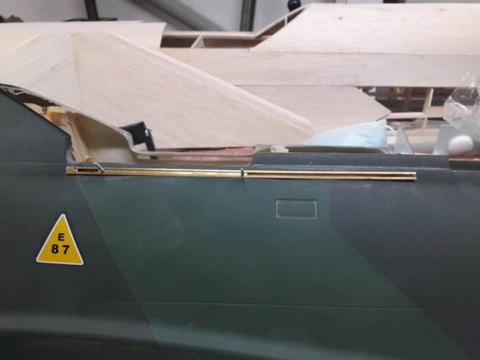
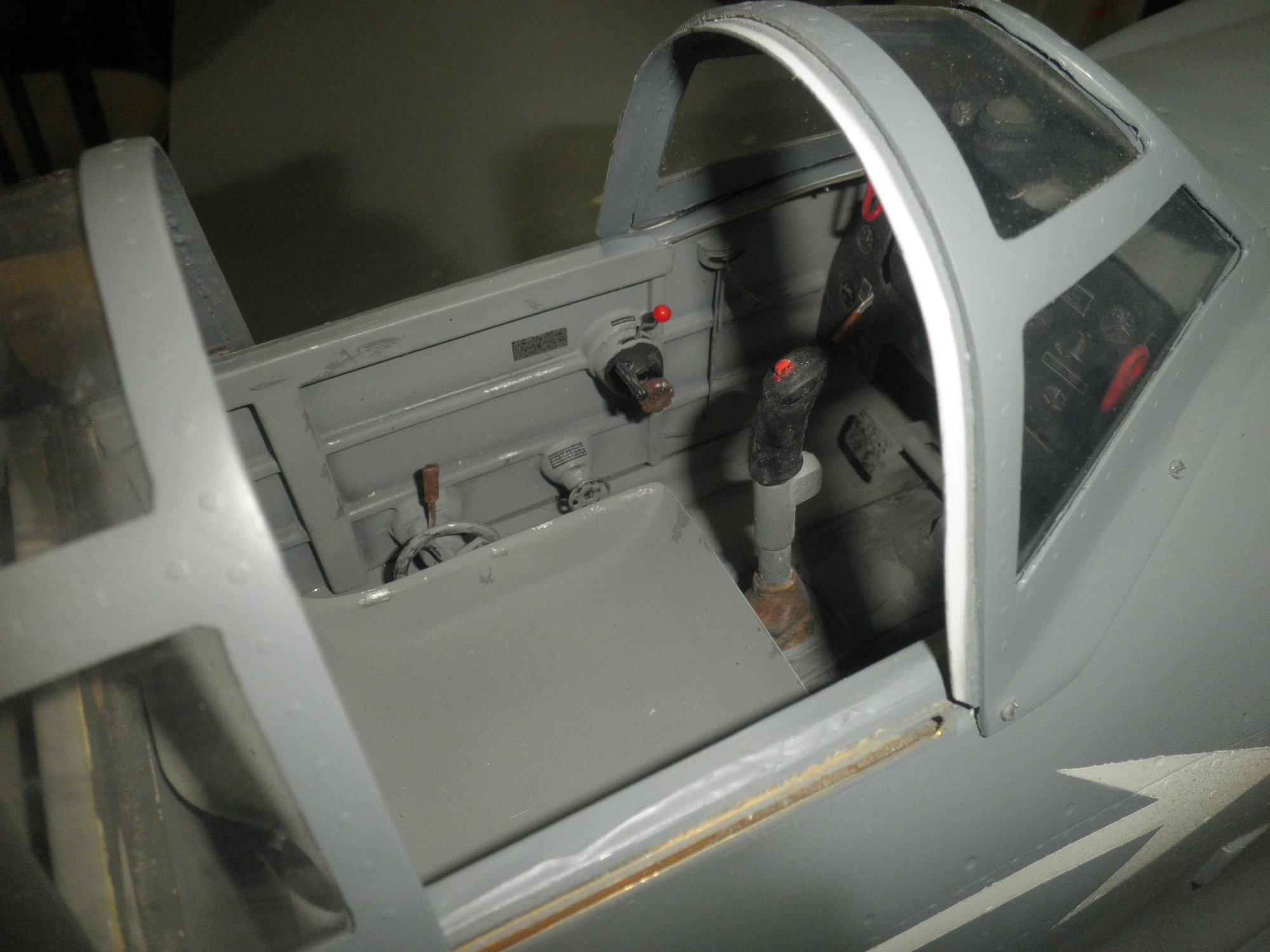
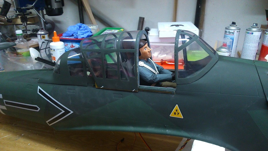
Repainting entire aircraft and fixing up cockpit a little. Was thinking of salvaging USAAF Insignias but they are out of proportion on wings so I cut my own stencils for everything.
Last edited by Cpig; 08-08-2017 at 05:49 AM.
07-05-2017, 04:09 PM
#331
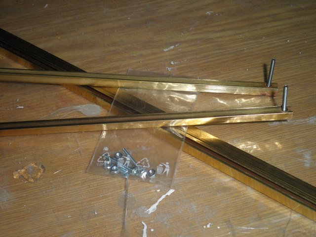
Built a radio box in CAD and got the fuel caps in from Chad Veich, Chad did a great job on the caps. Radio box is in primer / sanding stage now, will add cable details later.
Does anybody have a link or know what is written on the Radio box and battery box placards? I'd like to print my own.
Does anybody have a link or know what is written on the Radio box and battery box placards? I'd like to print my own.
Last edited by Cpig; 08-08-2017 at 05:51 AM.
07-06-2017, 05:15 AM
#333
My Feedback: (45)
There are three of these at my club including mine. I must have gotten a Friday afternoon build. My wings are flexing and I can't figure out what to do anymore to fix it, I'm thinking of drilling through the aluminum holders in the fuse into the tubes and using bolts to screw them together. Now my formers have all pulled away from the fuse as well. I can't score a win with this plane.
07-10-2017, 05:35 PM
#336
Almost done with radio compartment. Made the VRC-522 radio box but kept the original battery box (except for the small external attachment on the side that I made). May have to sand fuel caps down a little more flush.
Last edited by Cpig; 08-08-2017 at 05:46 AM.
02-11-2018, 12:29 PM
#339
Member
Join Date: Sep 2005
Location: Richmond,
VA
Posts: 50
Likes: 0
Received 0 Likes
on
0 Posts
Hey guys, Hoping to tap into your experiences with the TopRC P51. I have the Robart electric retracts with the Robart retract control unit. My radio is the Futaba T12FGA. From researching this and other forums, I still can't find a solution for the gear door sequencing. I've read about the ESM and the Assan gear door sequencers. Its not clear from reading the instructions if either is compatible with Robart retract control unit and if the Robart CU can be used if using an external gear door sequencer. Also there's no information I can find that the 12FG can support a program mix to sequence the doors like most of the newer radios. I'd like to know how you guys would add door sequencing using the hardware I have. I'm open to other external sequencers or other hardware to make it work. I'd appreciation all input!
Thanks,
Keith
Thanks,
Keith
02-11-2018, 06:04 PM
#341

I used the Asassin sequencer with the TopRc gear . Same situation. Get a Y-harness. plug it into the gear port on RX then both controllers into the Y.
Or you can: Take the gear door controller put it on an auxiliary channel slaved to the gear switch.
Or you can: Take the gear door controller put it on an auxiliary channel slaved to the gear switch.
Last edited by TimD.; 02-11-2018 at 06:10 PM.
03-14-2018, 09:45 PM
#343
[QUOTE=TimD.;12303898]can u give me the cg and where u measured it from. the pic is confusing realy do need help [email protected] thanks john


 07-21-2018, 01:27 PM
#346
Join Date: Aug 2012
Location: , IL
Posts: 31
Likes: 0
Received 0 Likes
on
0 Posts
Hello everyone. I just got the gunfighter version. This will be my first large scale build. The closest thing I ever built to this was the ESM Skyraider and a redwing RC MXS-Bach (both 30cc class). I will be asking some questions on here I hope someone is interested in answering them lol. This is a video off my youtube channel just to give anyone an idea of my skill level.
Not trying to get subs just wanting to give an idea of my skill level.
Here is my first question. I have the four blade spinner from gator for the plane. I was surprised that only compression locks the props in place. On my FMS 1700mm models there is screws that literally lock the props from rotating in the hub and changing the angle. If I am missing something let me know.( I understand this is a variable angle prop set up) The big question I have concerning the four blade spinner is the prop hub. It appears to me it needs to be drilled out in the center to fit over the prop shaft and the holes drilled in it with the back plate using my drill jig. If I am missing something anyone free to jump in and set my straight. Here is a list of the radio/servos/power board
Servos: Hi-Tec 645MG
Spektrum DX 9/AR9030T receiver
RedWing RC Black power board, using two 2100 Mah Life 4s 13.2 batteries, in redundancy, powering servos and ignition. (Yes the board has voltage regulation)
Power plant is torqpro 70cc 4 stroke.
Plan on installing nightfly led scale lighting including the landing light. That should be fun
Thanks
Ben
07-21-2018, 04:44 PM
#347
I have the four blade spinner from gator for the plane. I was surprised that only compression locks the props in place. On my FMS 1700mm models there is screws that literally lock the props from rotating in the hub and changing the angle. If I am missing something let me know.( I understand this is a variable angle prop set up) The big question I have concerning the four blade spinner is the prop hub. It appears to me it needs to be drilled out in the center to fit over the prop shaft and the holes drilled in it with the back plate using my drill jig. If I am missing something anyone free to jump in and set my straight. Here is a list of the radio/servos/power board
Servos: Hi-Tec 645MG
Spektrum DX 9/AR9030T receiver
RedWing RC Black power board, using two 2100 Mah Life 4s 13.2 batteries, in redundancy, powering servos and ignition. (Yes the board has voltage regulation)
Power plant is torqpro 70cc 4 stroke.
Plan on installing nightfly led scale lighting including the landing light. That should be fun
Thanks
Ben
The spinner does not determine if your prop locks in with compression or bolts; that is determined by your engine, which, on an aircraft this size should be four bolts. You will need to drill the spinner plate out to match your engine's bolt pattern.
07-21-2018, 05:21 PM
#348
Join Date: Aug 2012
Location: , IL
Posts: 31
Likes: 0
Received 0 Likes
on
0 Posts
That is a three blade, but its the same set up as the four. My question was, the prop hub, that those blades fit into, should have the center hole drilled out so it fits over the engine prop shaft?, then the using my prop jig, drill the four bolt holes in it, just like i will the back plate? The compression part is how the blades/props are actually held into the prop hub. From what i can tell, it is just the compression of the hub being bolted together, that compresses down on the blade holding it in place and not allowing it to spin and change its angle.
Thank you very much for the reply Cpig
Last edited by benjack71; 07-21-2018 at 05:24 PM.
07-22-2018, 06:39 AM
#349
Oh, I totally understand that. Allow me to clarify. I am referring to the actual props themselves locking into the propellor hub. My big question was drilling out the center hole of the prop hub to slip over the engine prop shaft. I have a drill jig for drilling the back plate, and I assume the propellor hub as well. Yes, it is four bolts, just like me DLE 30cc. The bolt pattern on my torq pro is the same as a DLE 55, that is why my prop jig will work fine for drilling out the four holes. Trying to think of a better way to rephrase it.
That is a three blade, but its the same set up as the four. My question was, the prop hub, that those blades fit into, should have the center hole drilled out so it fits over the engine prop shaft?, then the using my prop jig, drill the four bolt holes in it, just like i will the back plate? The compression part is how the blades/props are actually held into the prop hub. From what i can tell, it is just the compression of the hub being bolted together, that compresses down on the blade holding it in place and not allowing it to spin and change its angle.
Thank you very much for the reply Cpig
Last edited by Cpig; 07-22-2018 at 06:44 AM.
07-22-2018, 08:38 AM
#350
Join Date: Aug 2012
Location: , IL
Posts: 31
Likes: 0
Received 0 Likes
on
0 Posts
Yes Ben, in fact, I had that same 3-bladed prop on my Spitfire and you have to do the same thing, drill the hub out to match your engine bolt pattern. Note on that prop assembly, the indexing marks that they had on mine to mark blade pitch were not accurate at all so I used a piece of scrap triangle wood stock to make a jig so I could get the exact same pitch on all blades. You'll also have to balance to minimize shaking your plane apart. The props hold their pitch well under the compression the the hub bolts provide. That prop worked great tho, I loved it.

