PBY Catalina (Vintage Plans) Build Thread
 08-25-2021, 06:09 PM
#101
Senior Member
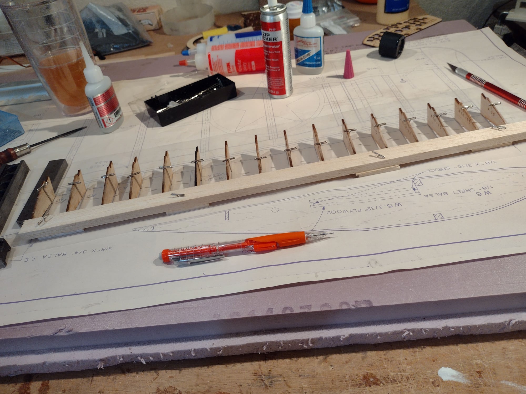
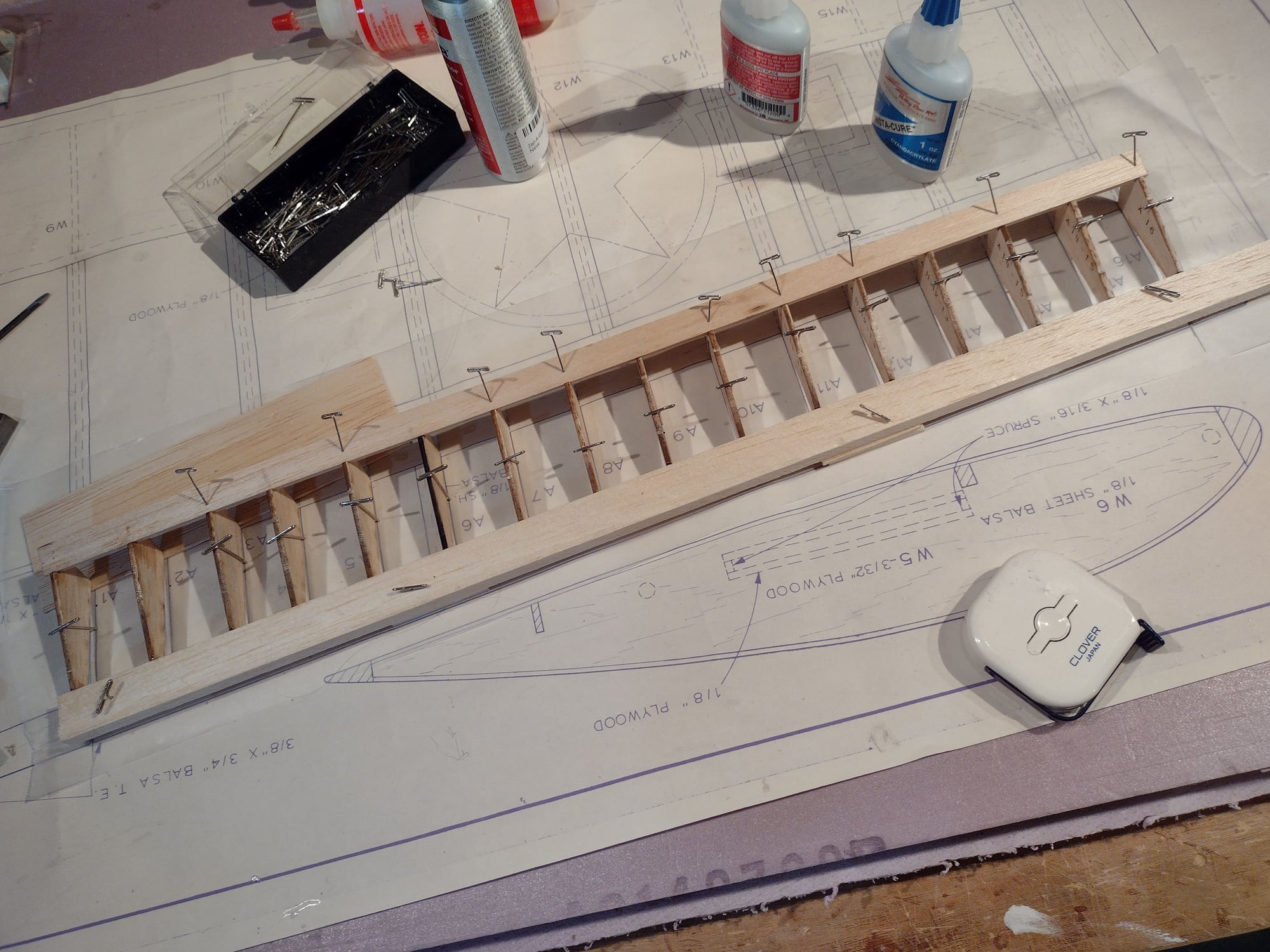
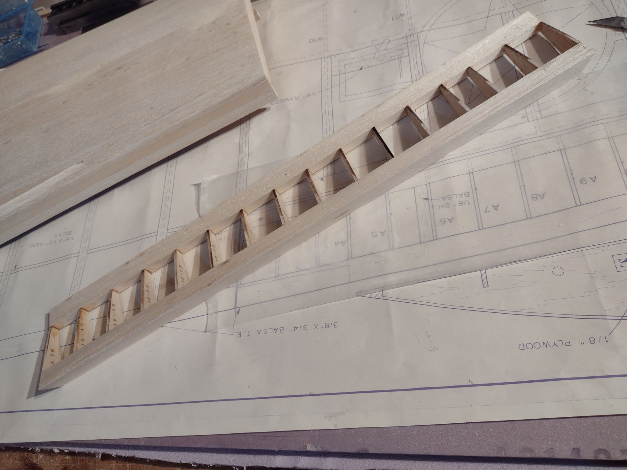
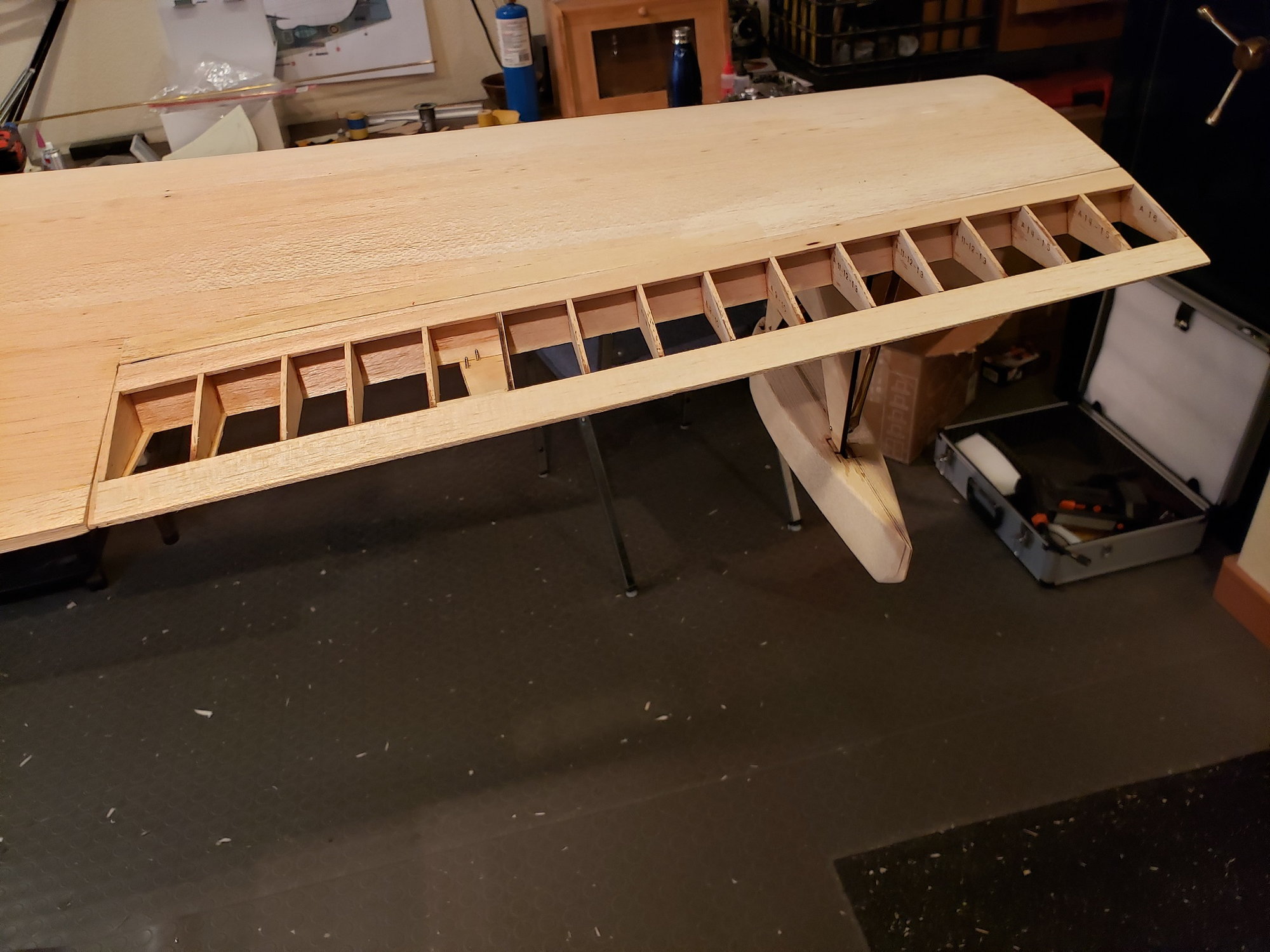
Building the ailerons, pretty straight forward stuff. The one thing is that the ribs do not have a 90 degree corner. The LE and TE of each rib is at some non-right angle. so I elevated that TE.
 08-25-2021, 07:59 PM
#102
Senior Member
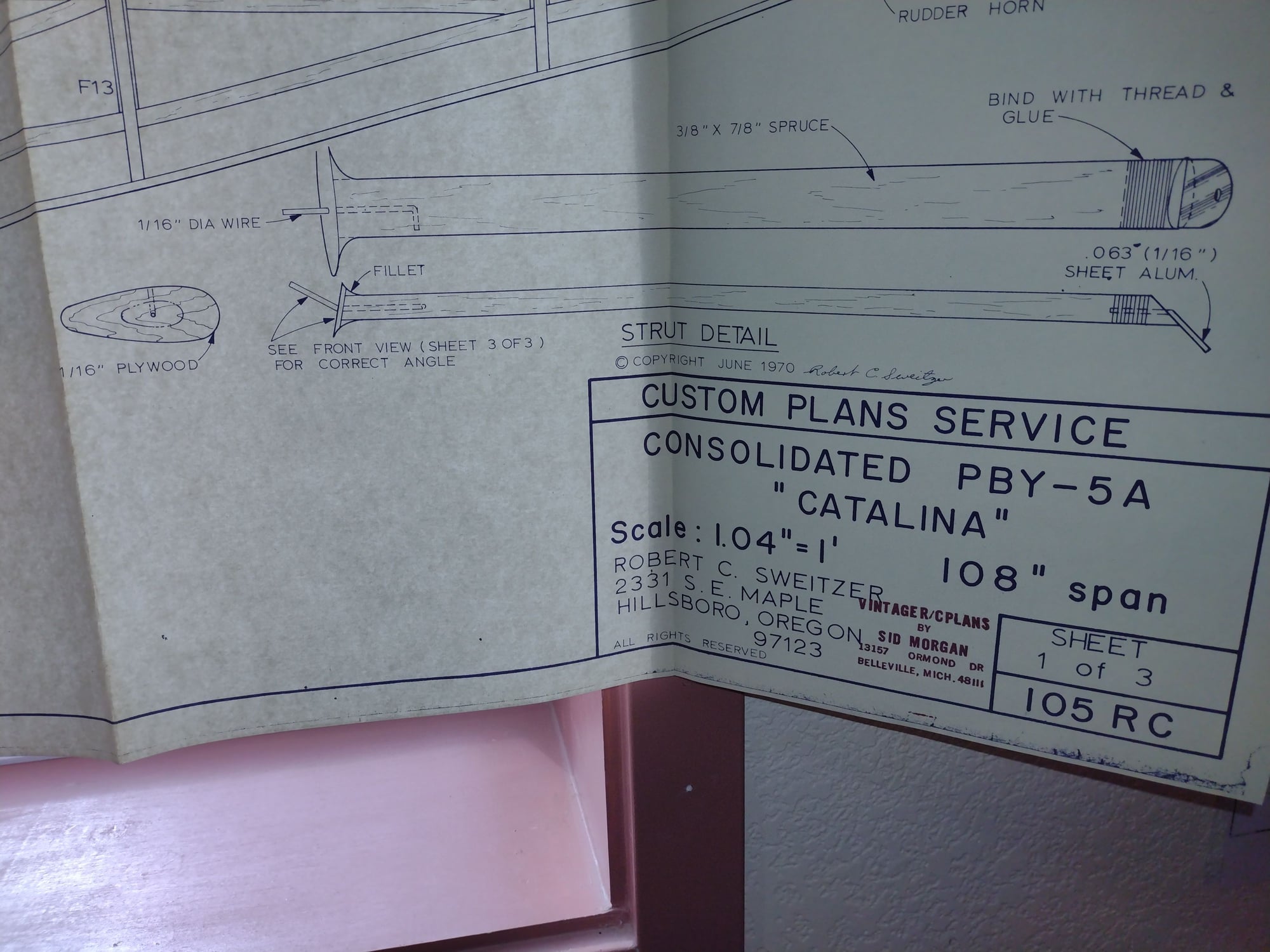
I've added the wing struts. But I did not like the designer's approach. He used spruce with some wire in the lower end and a thread wrapped metal tab at the top. Here's a pict of the design in the plan. An important thing to note is that these do not carry any load, decorative only.
08-25-2021, 08:04 PM
#103
Senior Member
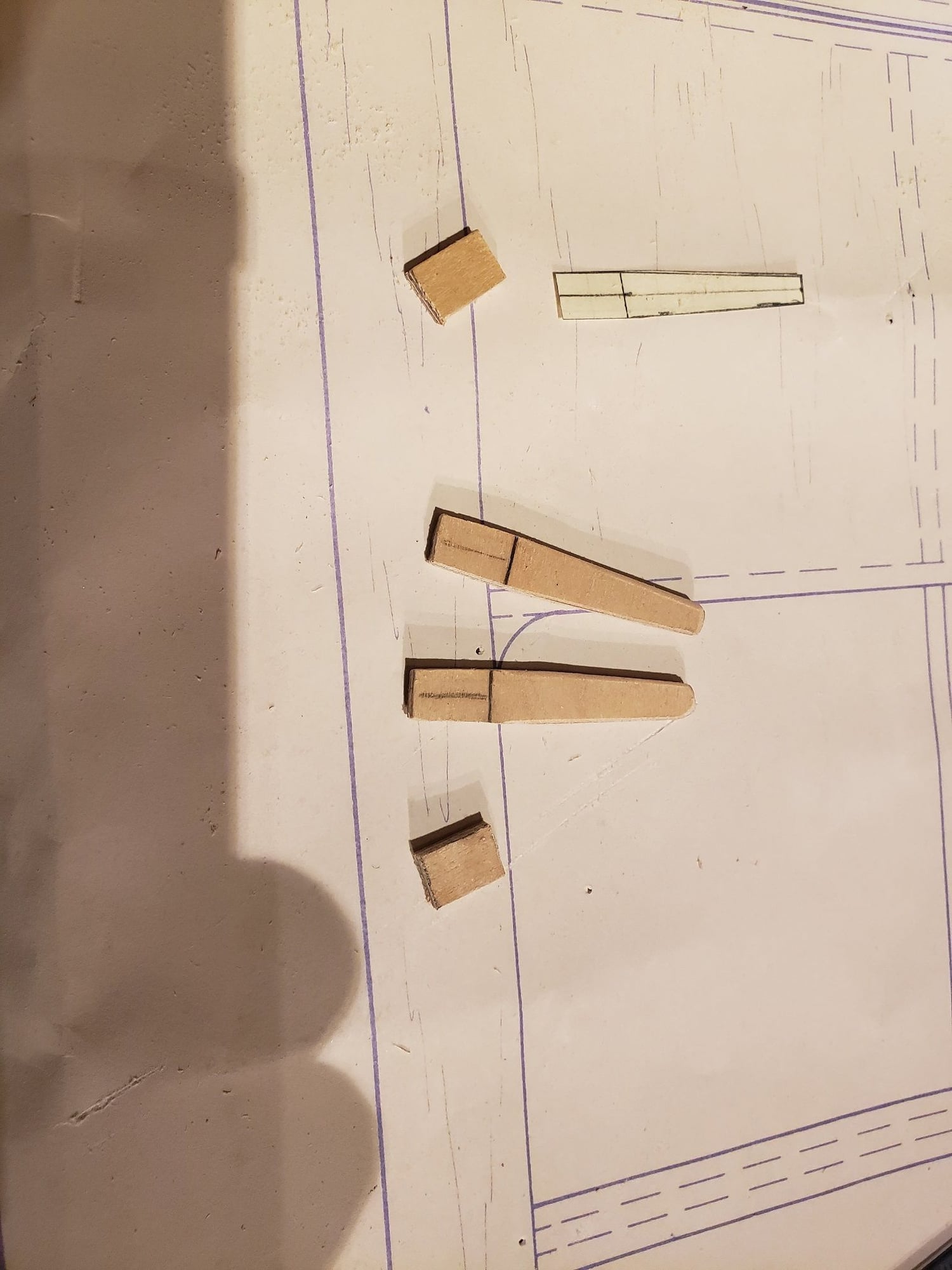
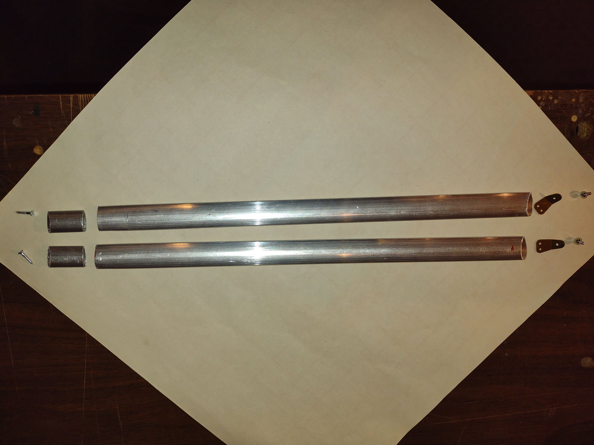
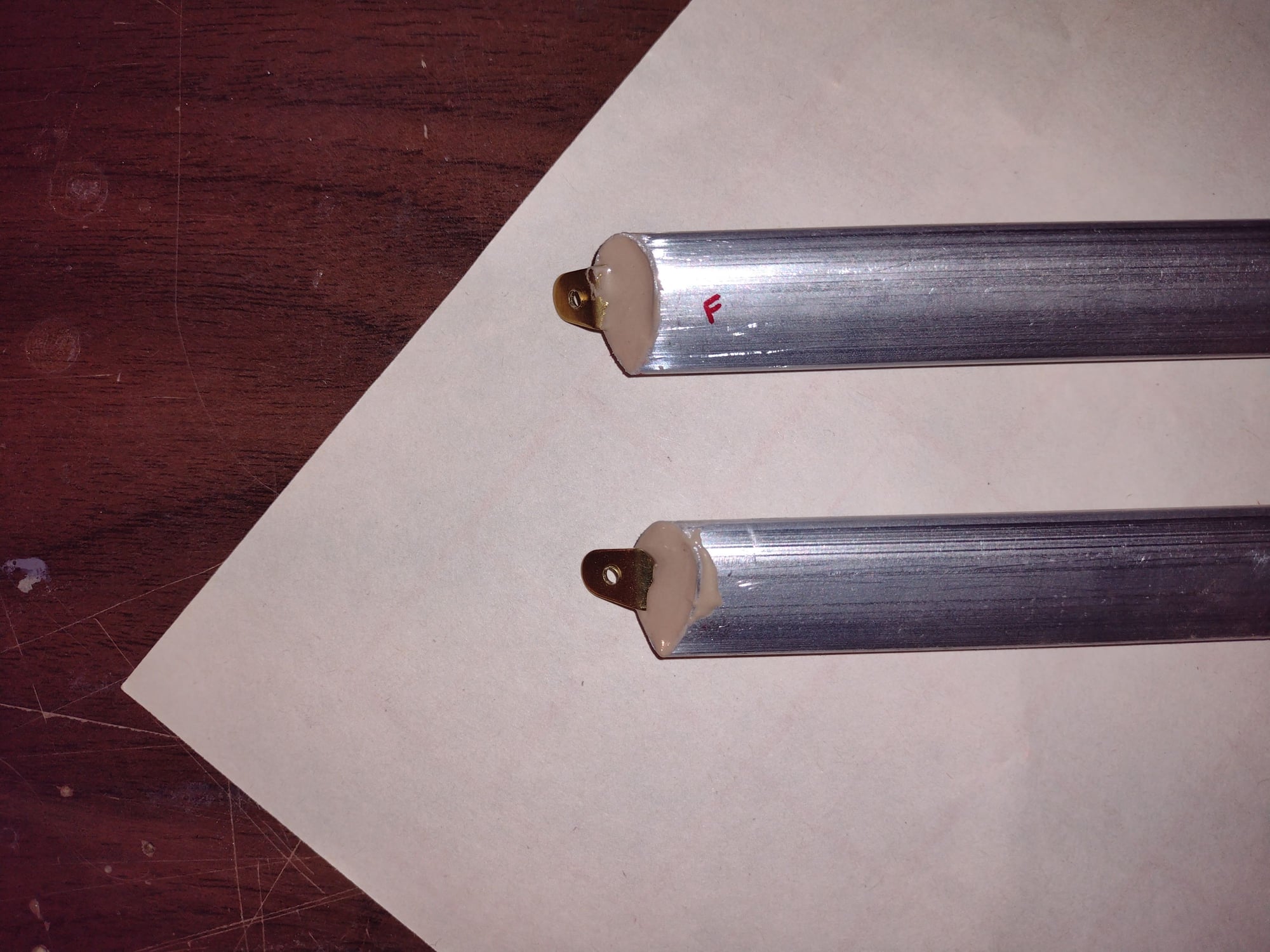
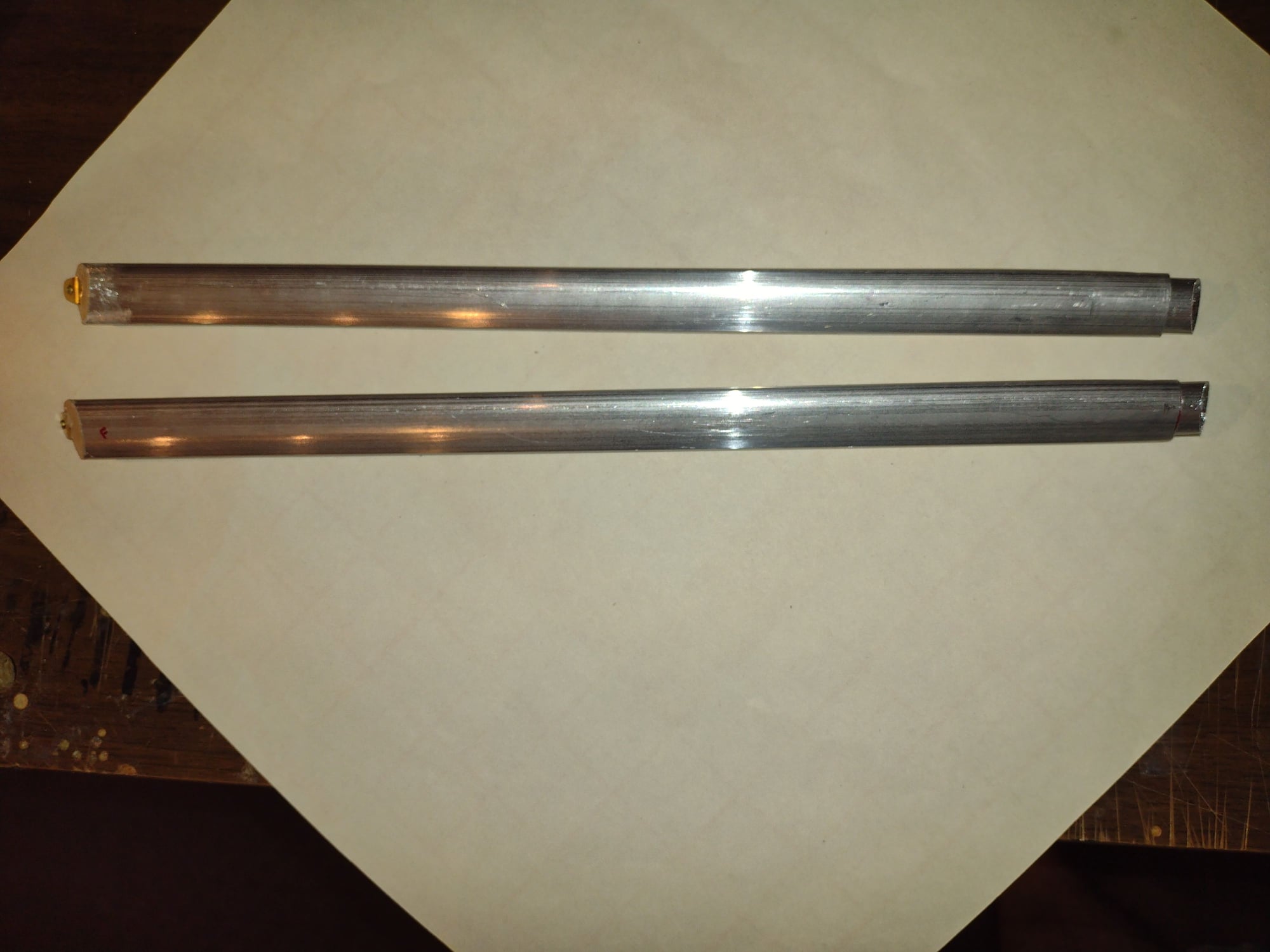
I wanted something that would look better and be easy to install. I used streamlined aluminum tubing.
This pict shows all the parts for 2 of the struts. The short tubes will get secured to the fuse. The long tubes will have the tab glued into the top end and slide over the smaller tubes on the fuse.
This pict shows all the parts for 2 of the struts. The short tubes will get secured to the fuse. The long tubes will have the tab glued into the top end and slide over the smaller tubes on the fuse.
08-25-2021, 08:08 PM
#104
Senior Member
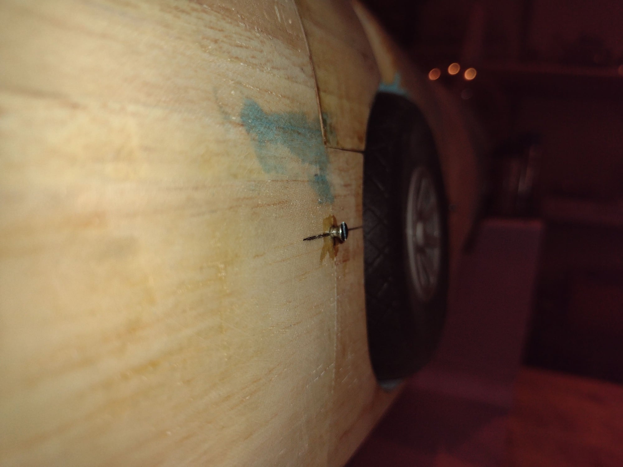
Small tubes glued to the fuse. first the screw is glued into the fuse, leaving 3/8" sticking out. then the small tube glued (epoxy + filler) over it. gives extra mechanical holding for the fuse tubes.
 09-07-2021, 01:30 PM
#107
Senior Member
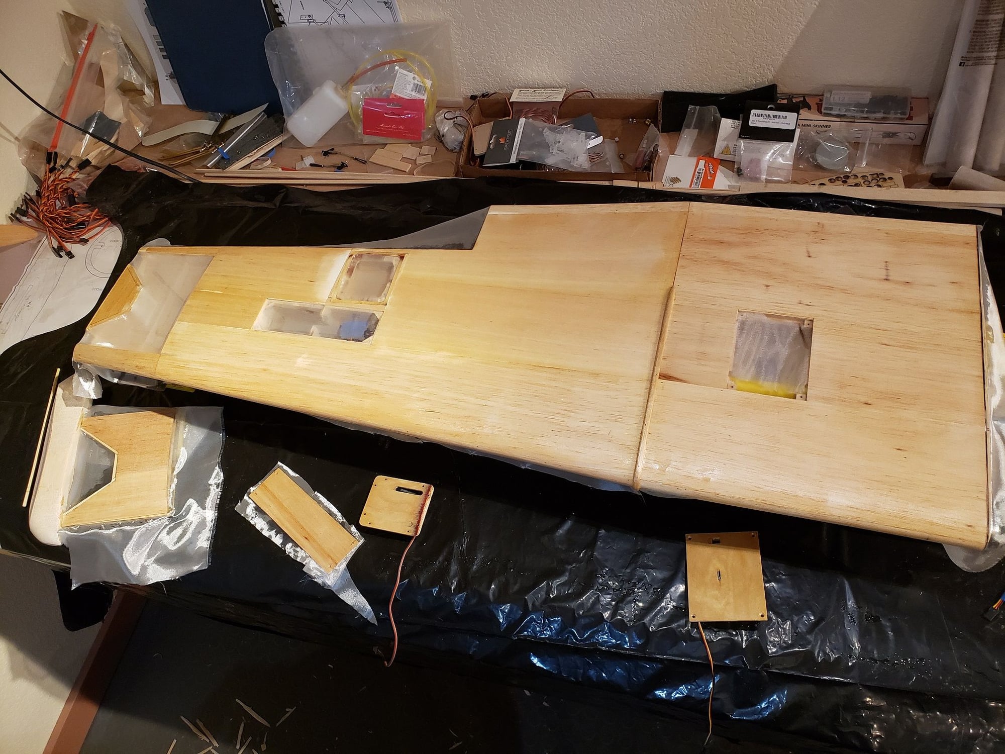
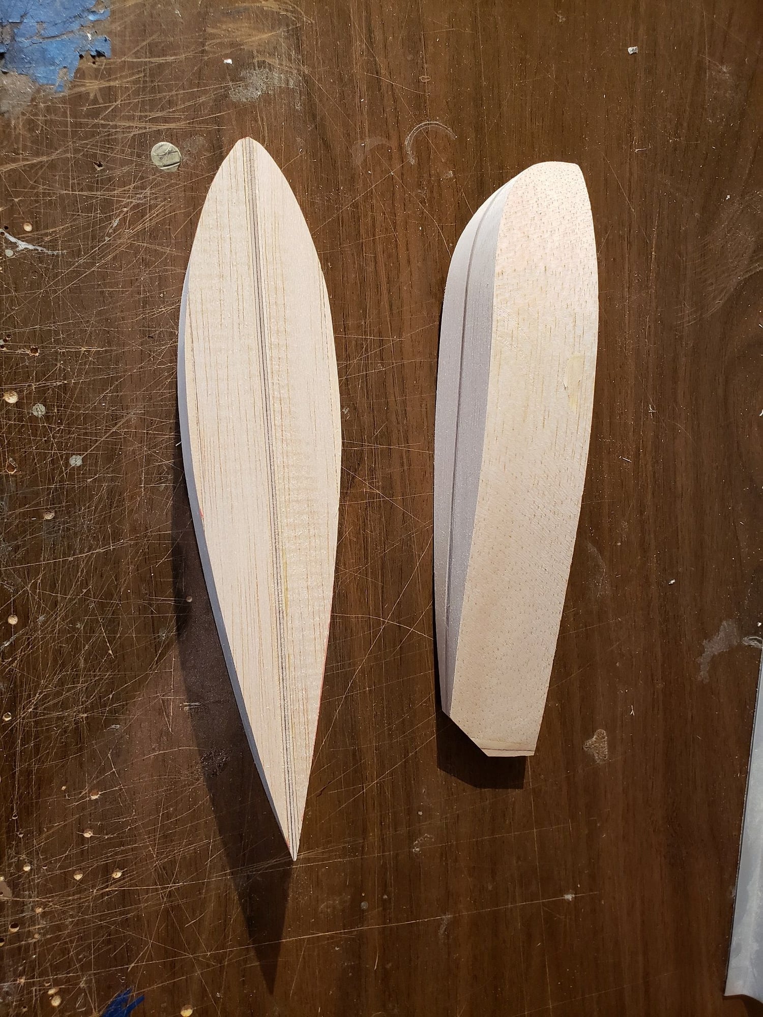
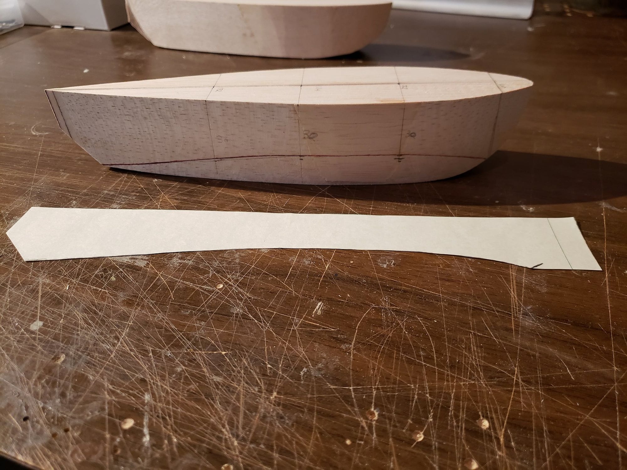
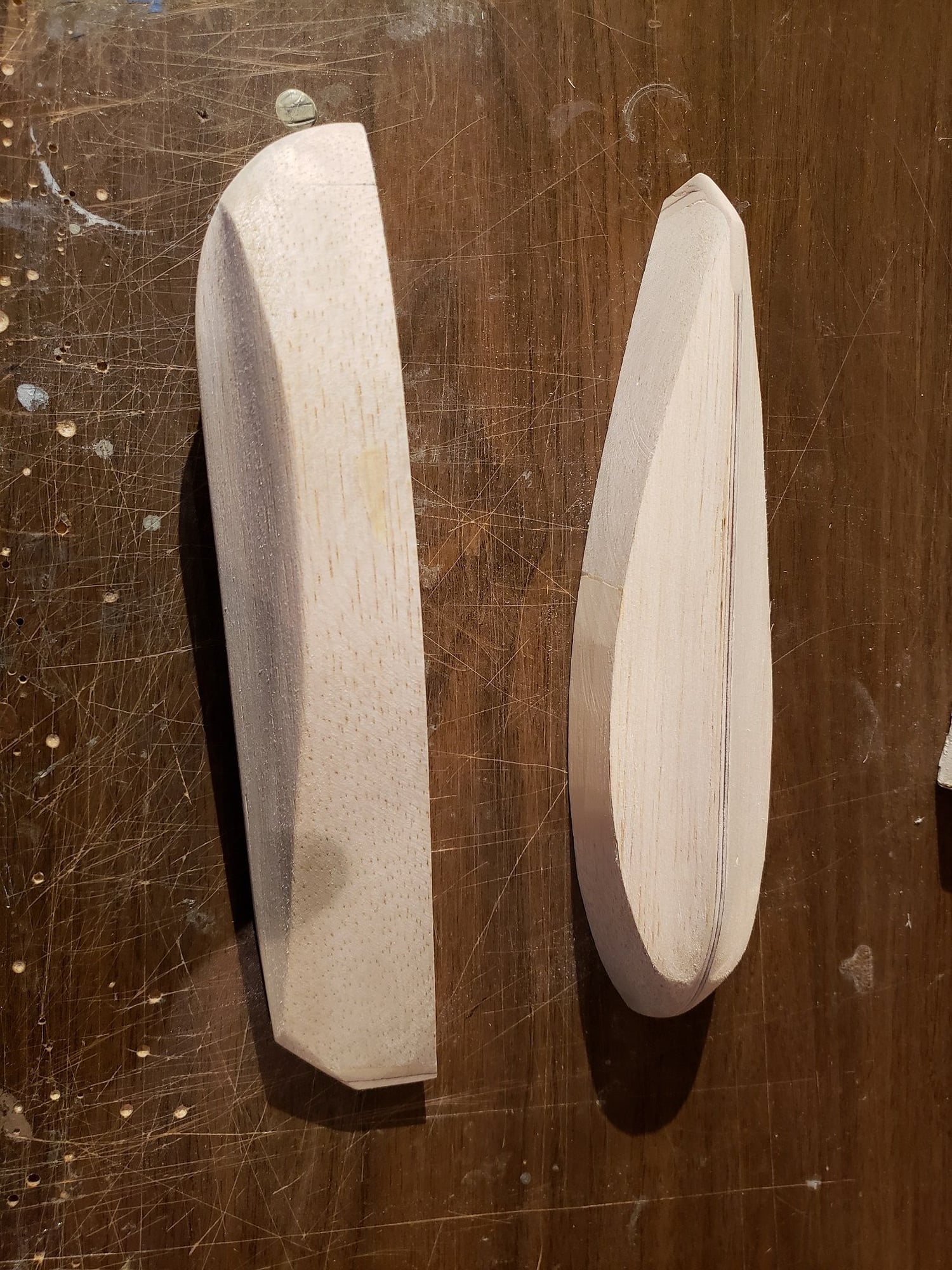
Building the floats. Made some basic templates. Cut 1/8" ply for the centerline and glued balsa to the sides of that. Then incrementally shaped based on section views on my reference docs.

09-07-2021, 01:39 PM
#108
Senior Member
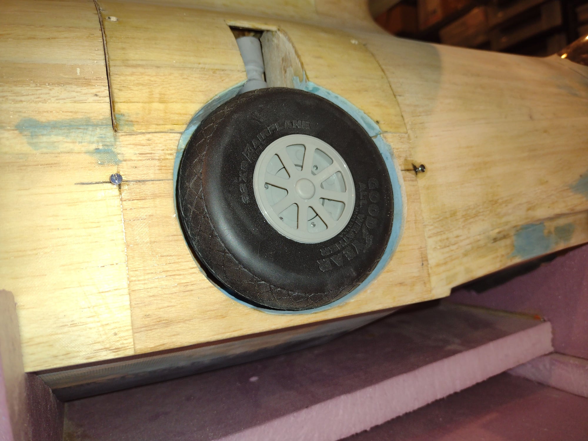
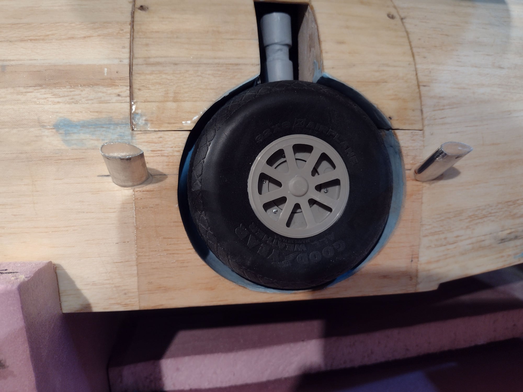
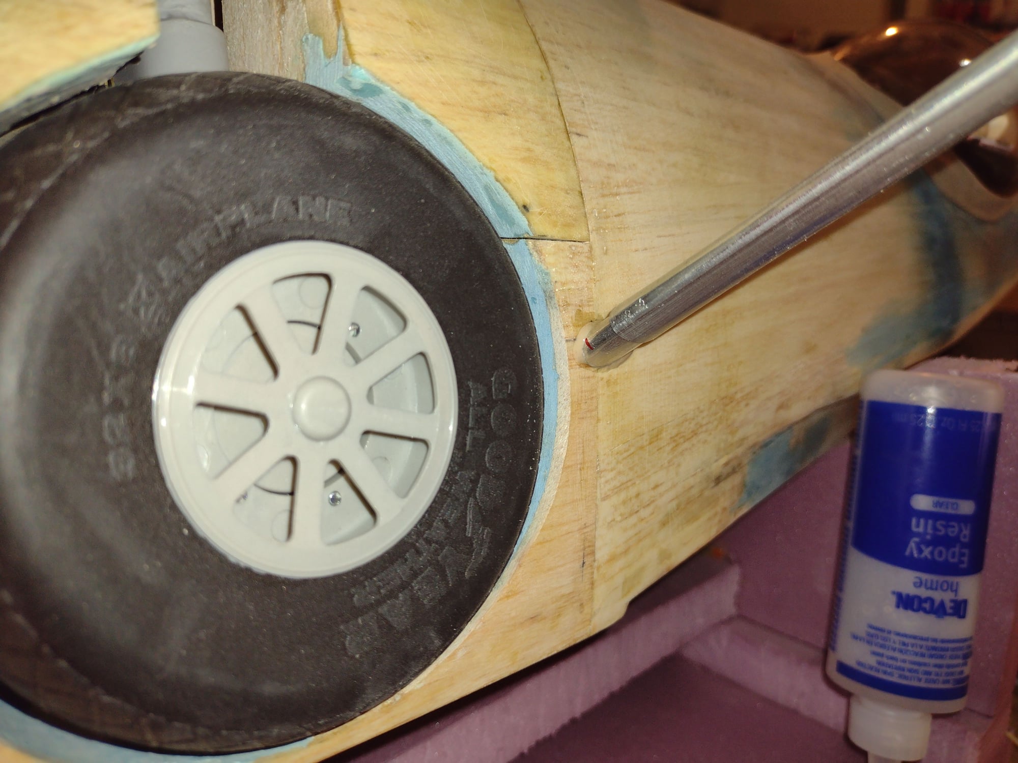
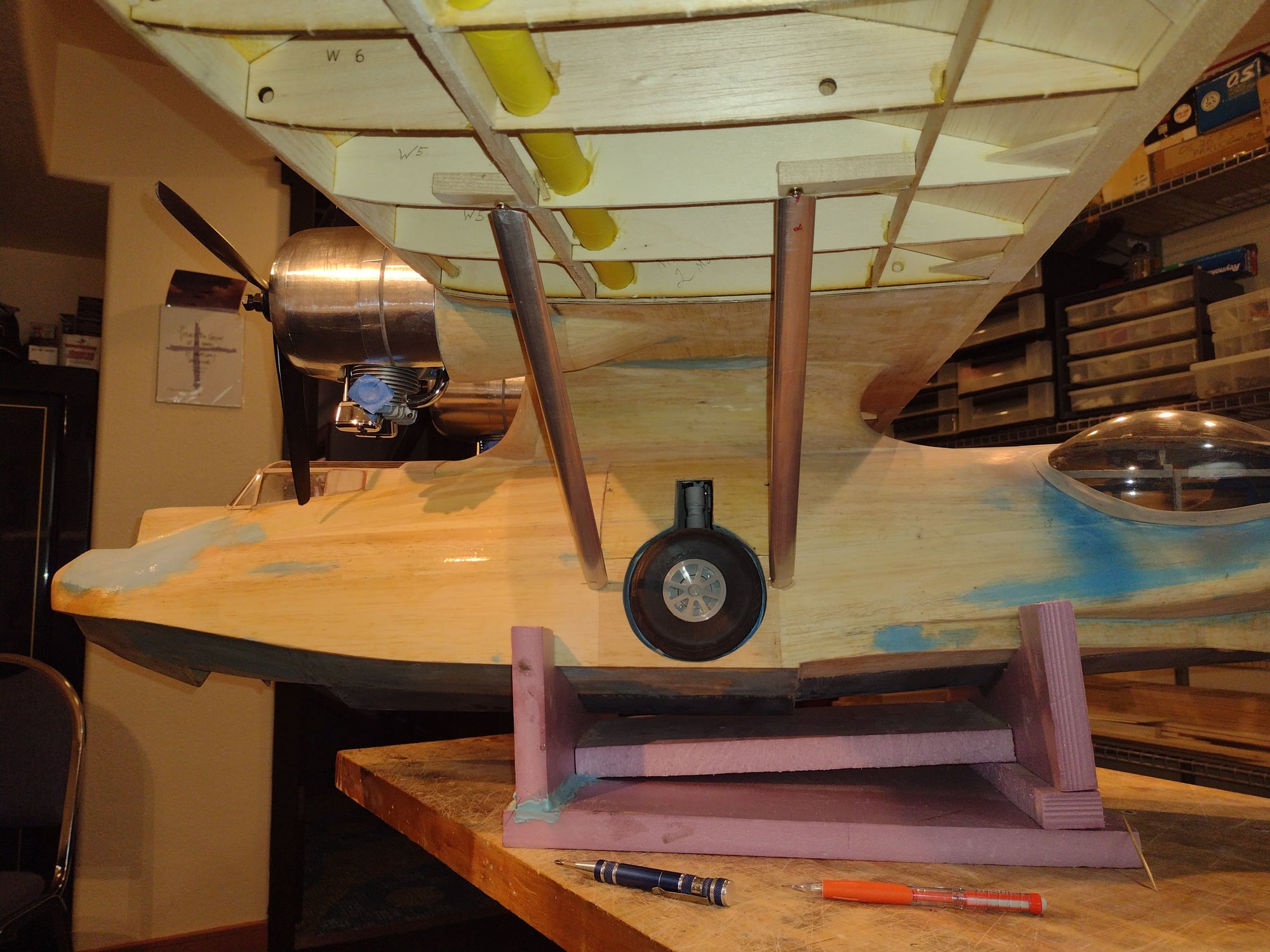
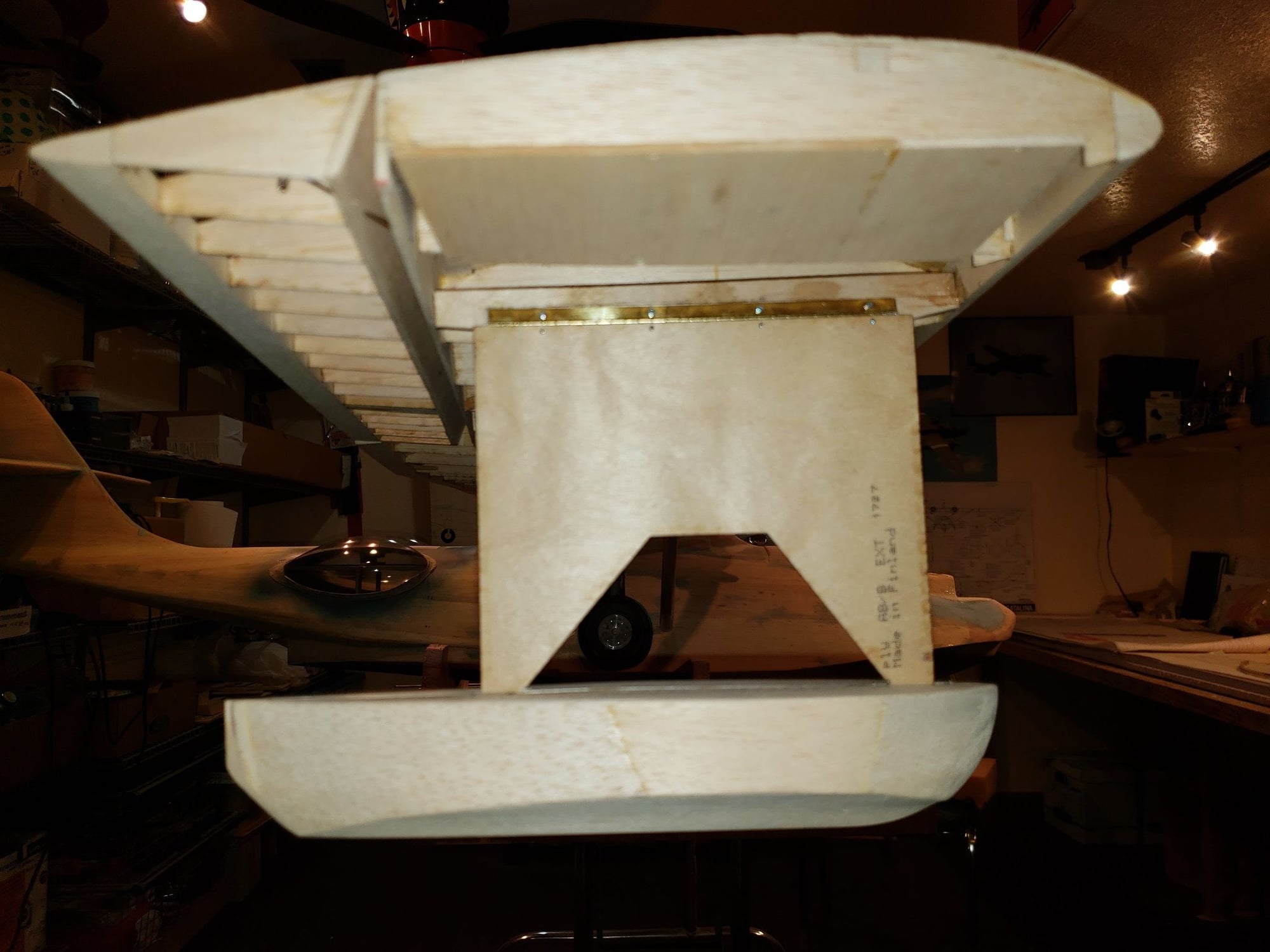
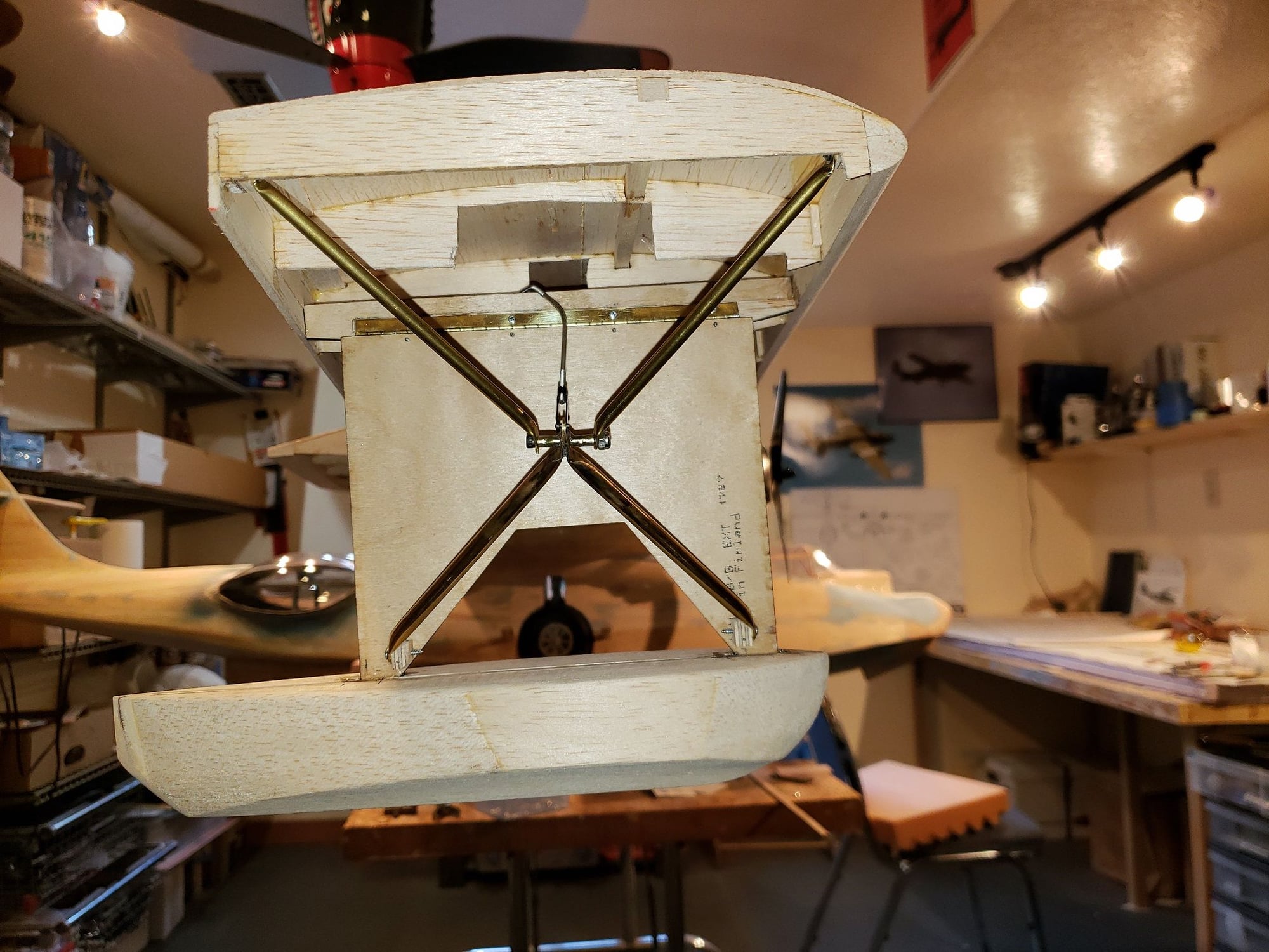
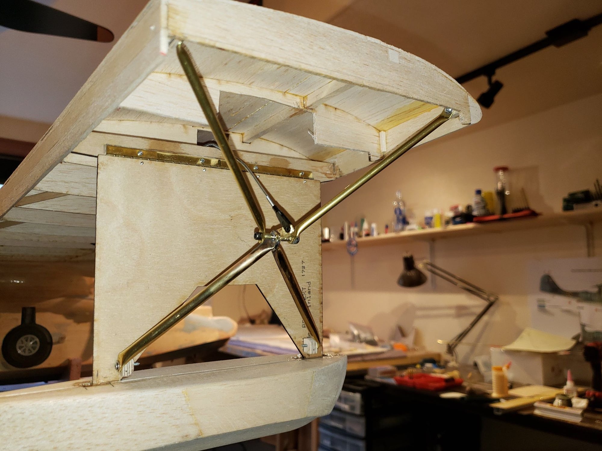
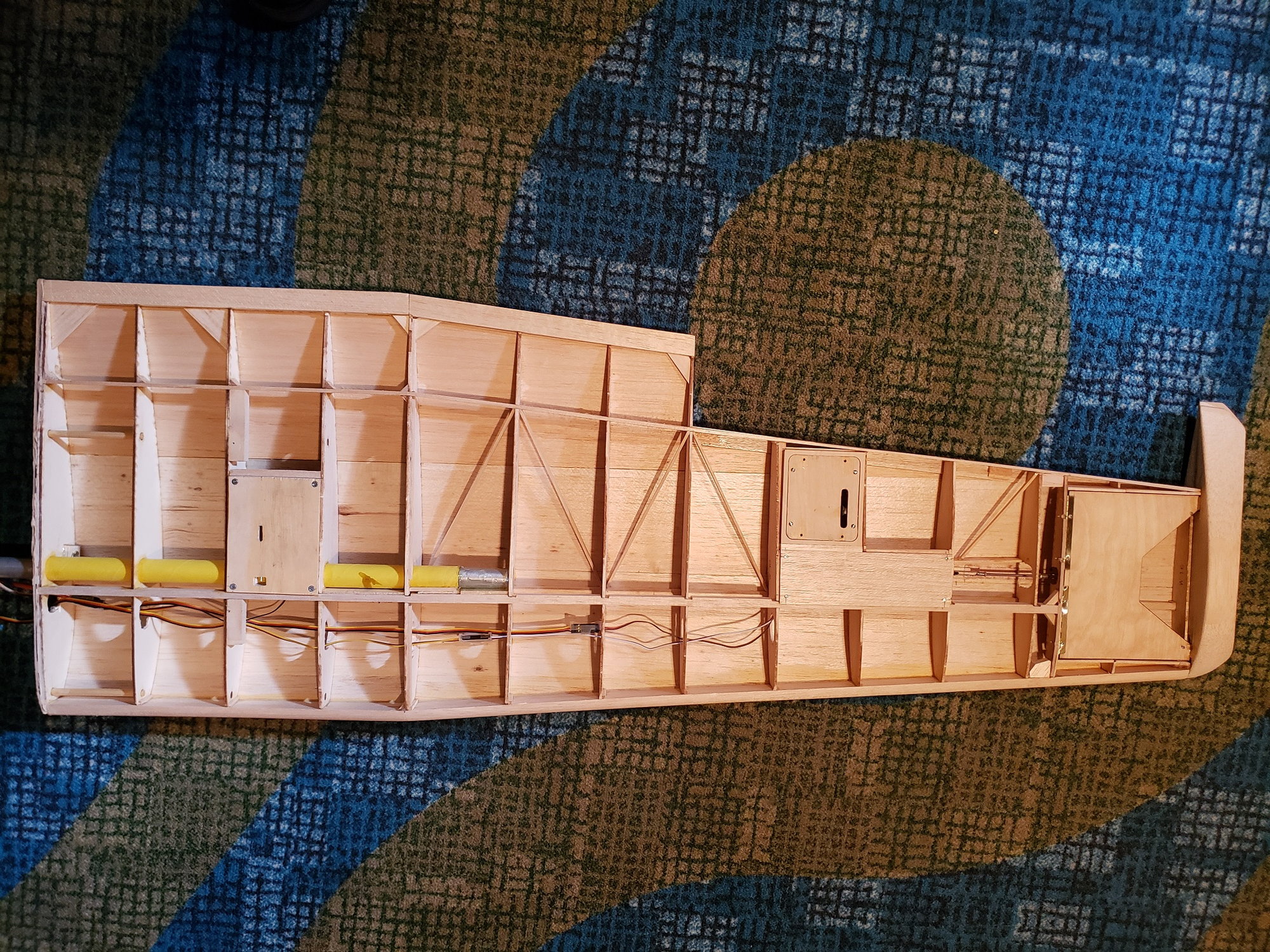
I mounted the first float and built a roughly scale retract mechanism. These are both installed. Next working on the actuator for the retract.
For mounting the float pylon, the plan has a couple of 3/32 wires bent in a offset Z shape mounted in brass tubes. I chose piano hinge as simpler.
I didn't provide any picts of the process of figuring out and building the retract. If people are interested in the details, let me know and I will add a few posts and pictures.

 09-11-2021, 03:57 PM
#111
Senior Member
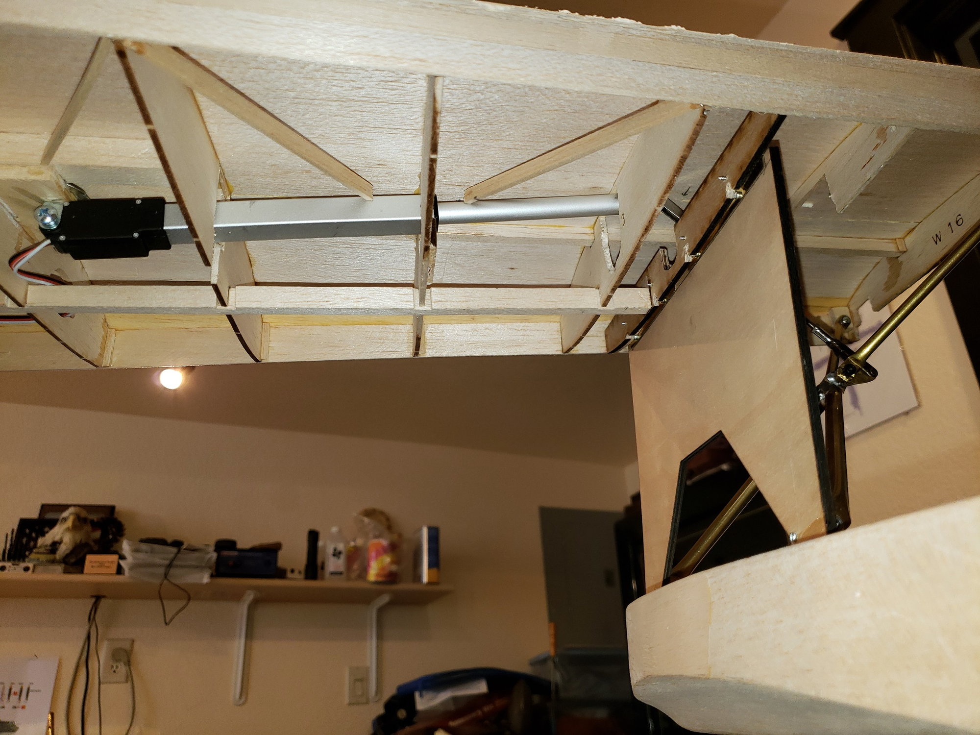
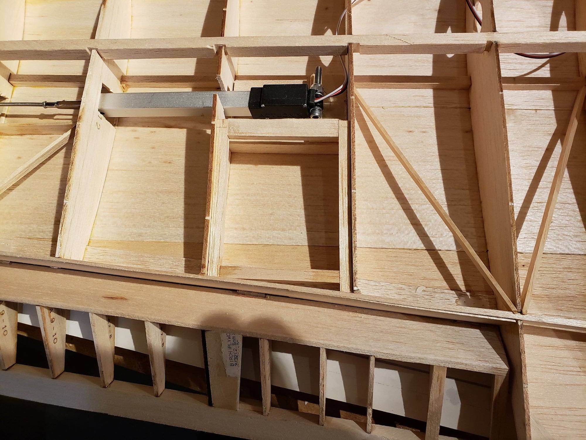
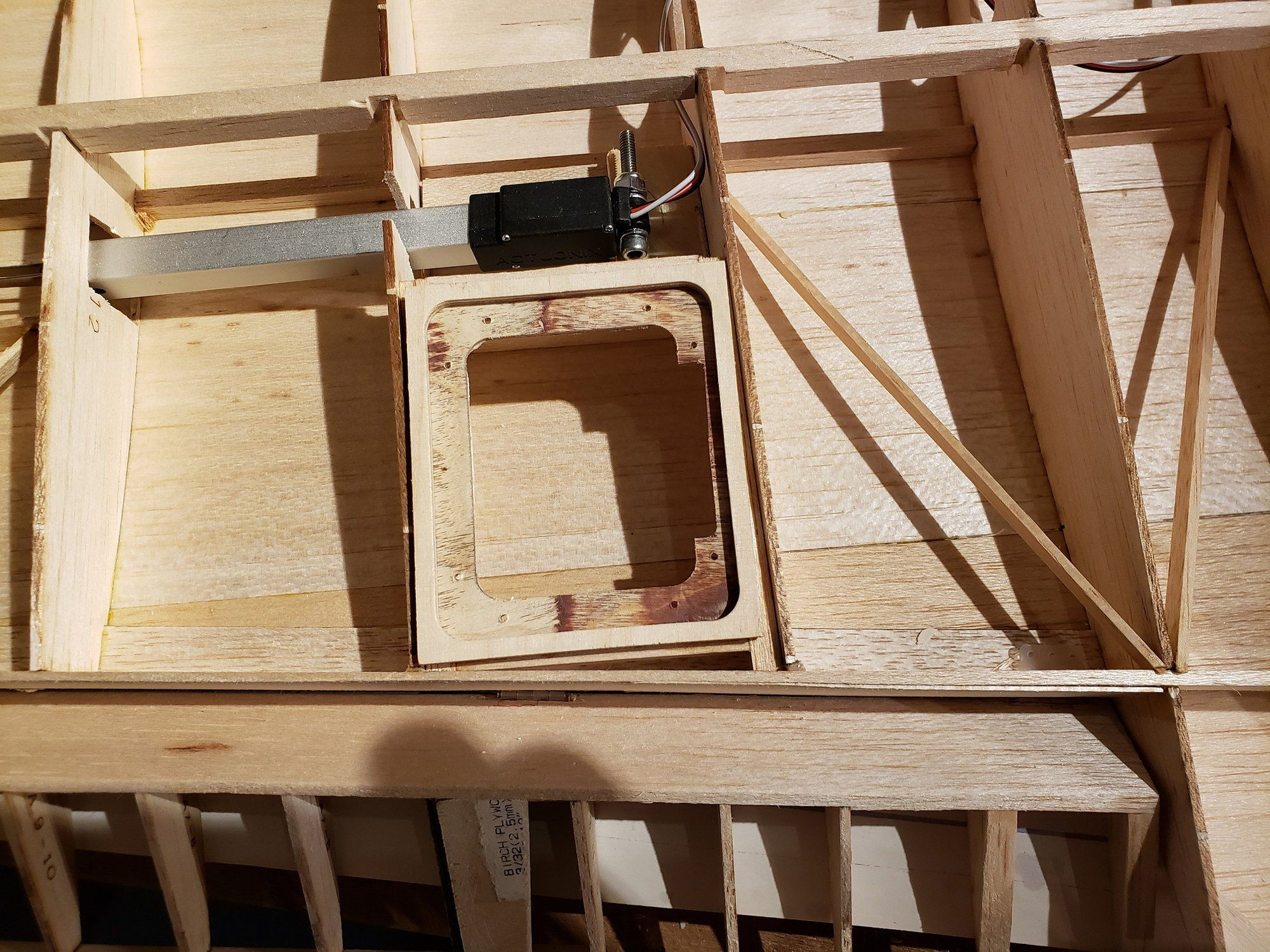
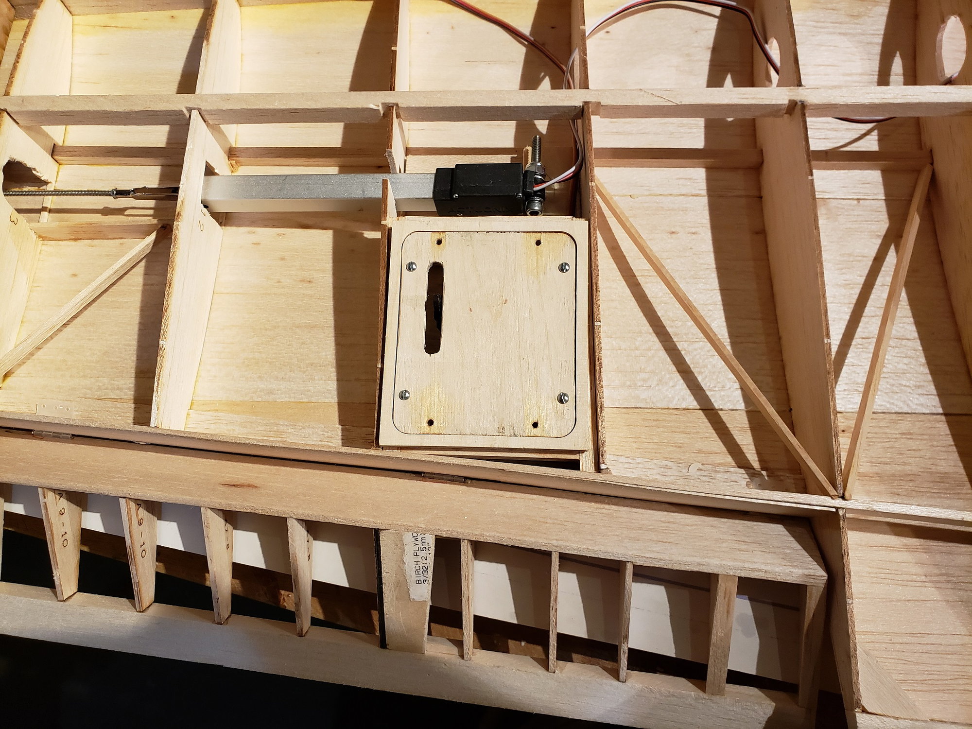
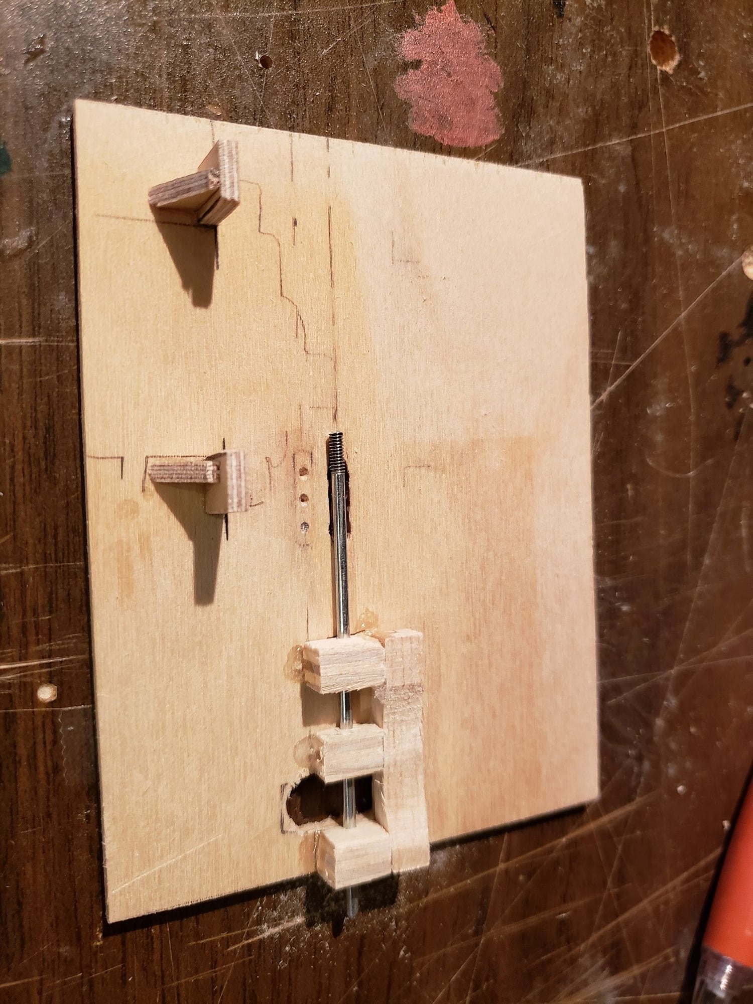
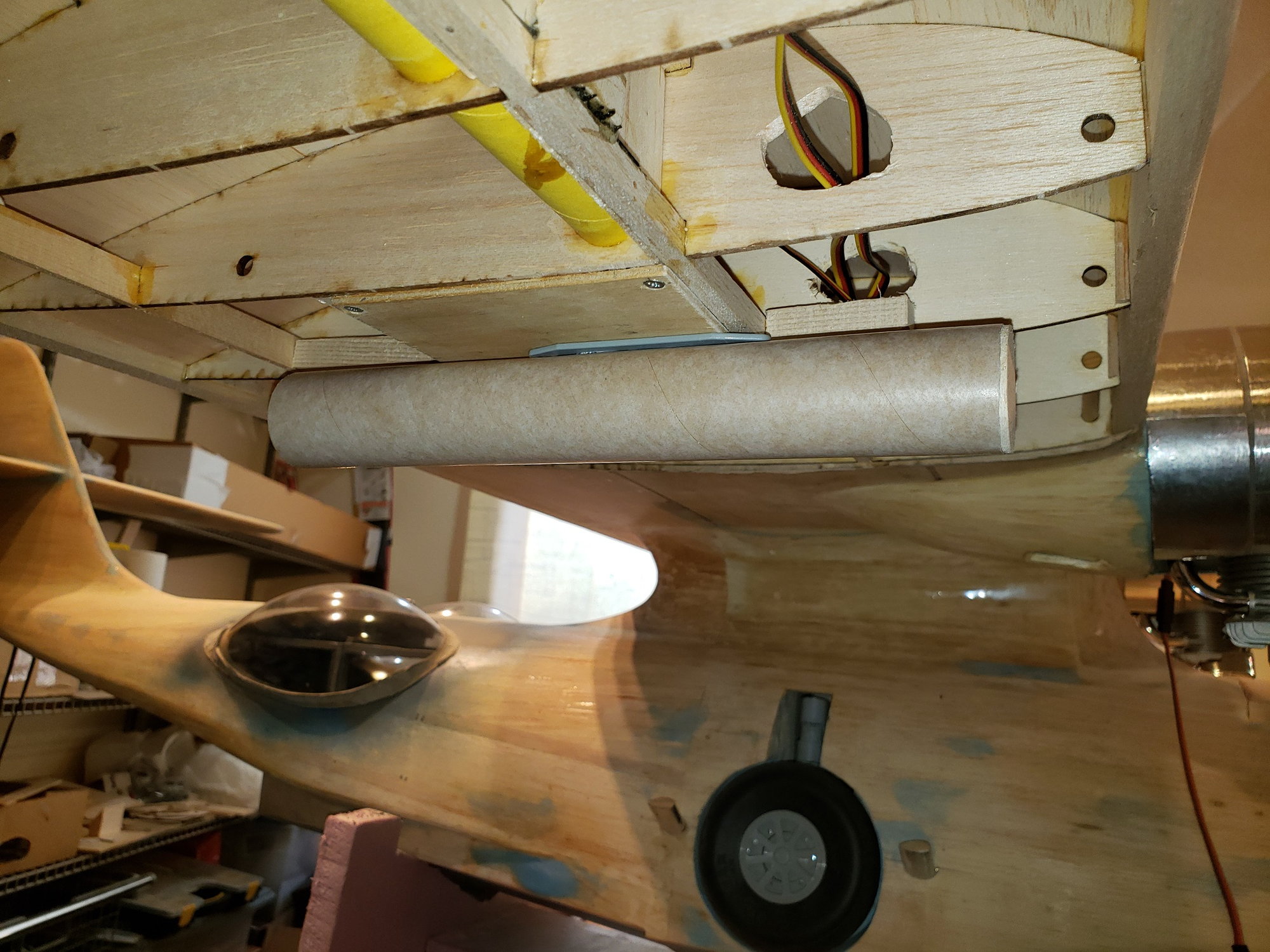
Working on actuating the float retract mechanism. The rod connected to the lever at the center of the 'X' requires a travel of 4" (100mm) to transition the float from down to up. I don't have any servos to do that 
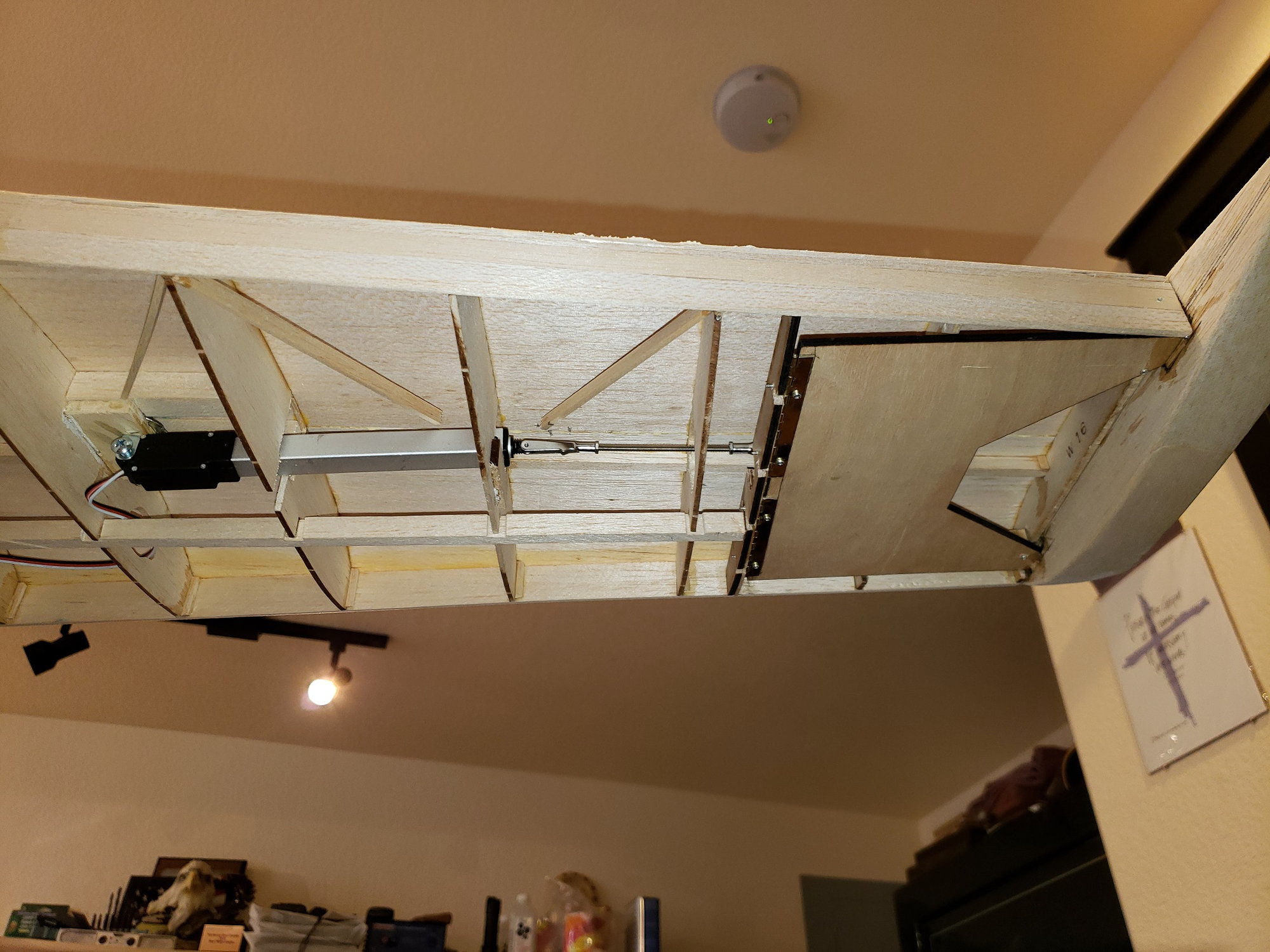
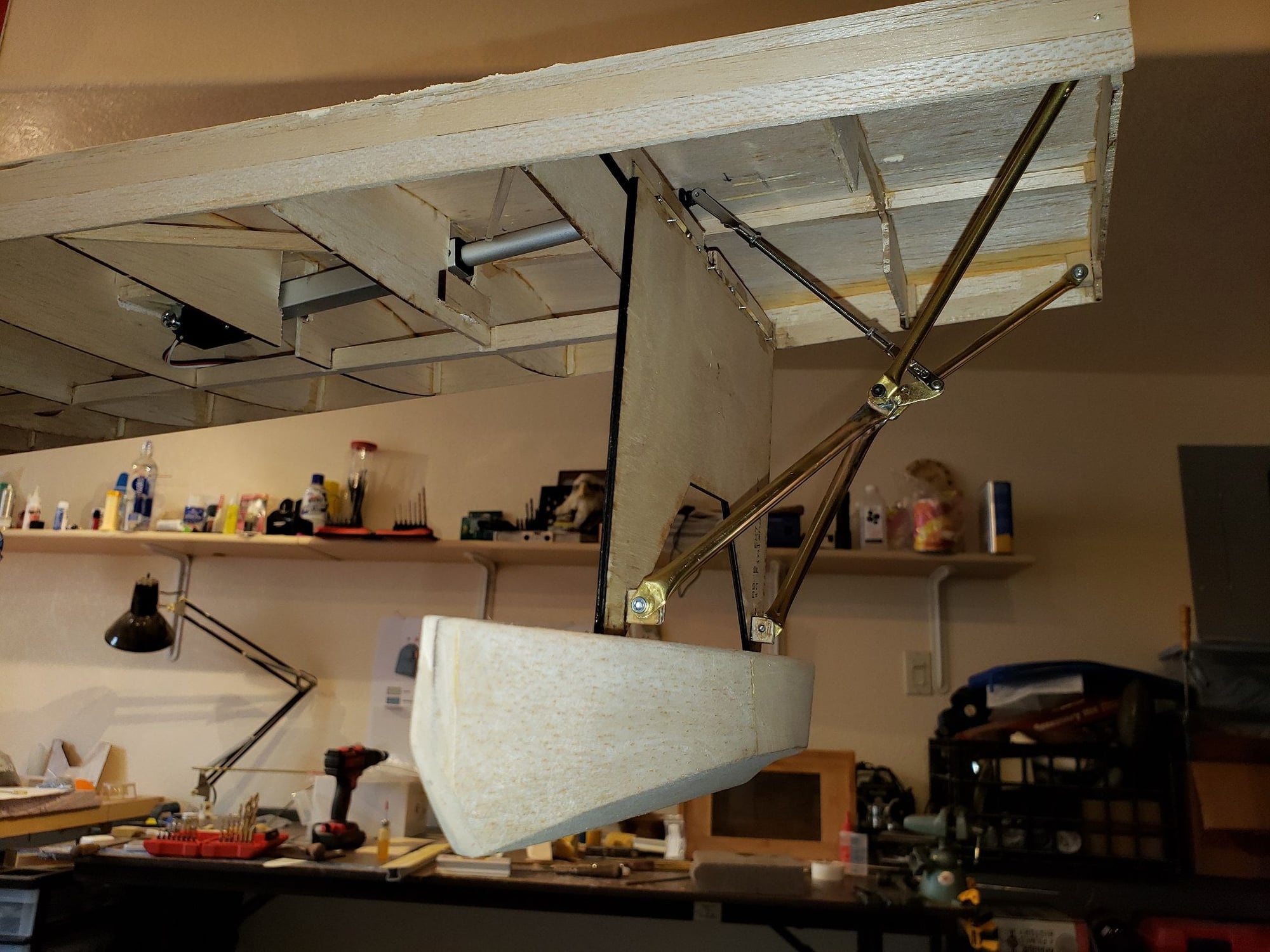
I looked at a pneumatic ram, but Robart's only have travel of up to 2.5". I found a linear actuator from Actuonix that will cover the distance. They actually have a few that would work. I chose the "L12-R Micro Linear Servos for RC". Several gearing options, I chose 210:1. It will generate several pounds of force, more than enough to move the float. Just as important, it will HOLD the float very positively in the up or down position with no current draw. The L12-R only weighs 56g. One thing I will need to address is the current draw threw the receiver. Each L12-R has a stall current of 460mA.
Here it is installed.
 09-30-2021, 07:25 AM
#116
Senior Member
Ordinance. One of my favorite topics. 😊
I originally picked the Catalina/Canso as a project just because I always saw it as a very cool and unique looking sea plane. Once I began researching the plane I learned of it�s incredible combat role. Cats really did it all. Some of you are probably well aware of it, but I�ll touch on it for those who aren�t. Beyond roles of patrol, rescue, and ferrying she took on anti-submarine, commerce raiding, bombing coastal installation, minelaying, and deployment / retrieval of various special operations personnel.
Digging into the anit-submarine missions is rather thrilling reading. Running gun battles as Cats make runs on submarines in 225mph dives while the sub crew is shooting back. Of course, this makes the Cat rather vulnerable as 225mph is a _slow_ attack run. Putting it in perspective, the A-26 Invader made diving runs at 425mph. Various Cats were upgraded in the field with fixed .50 Cal and 20mm guns in the nose to help suppress the fire from subs.
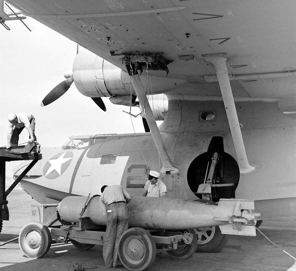
Back to ordinance. The Cat could carry bombs, depth charges, torpedoes, and mines. There were 3 hard points under each wing. She could carry roughly 2,000lbs on each side. The inner station was for torpedoes and mines. The outer 4 stations were for bombs and depth charges. Aircraft were eventually equipped with radar and some with "magnetic anomaly detection" gear (MAD). The latter used a special weapon called the "retro bomb", which had a rocket motor to stop its forward momentum when dropped.
On my plane I will initially set up the inner hard points. One item I am working to replicate is the Mk-1 Air Deployable Anti-Ship Mine. This mine had a parachute that slowed its entry into the water. If I can replicate this, it would be rather cool when dropped from the model. There is a good video on how air deployed sea mines work and are used.
The Mk-1 mine.

Hard points are visible here. The torpedo is being loaded to the inner point.
I originally picked the Catalina/Canso as a project just because I always saw it as a very cool and unique looking sea plane. Once I began researching the plane I learned of it�s incredible combat role. Cats really did it all. Some of you are probably well aware of it, but I�ll touch on it for those who aren�t. Beyond roles of patrol, rescue, and ferrying she took on anti-submarine, commerce raiding, bombing coastal installation, minelaying, and deployment / retrieval of various special operations personnel.
Digging into the anit-submarine missions is rather thrilling reading. Running gun battles as Cats make runs on submarines in 225mph dives while the sub crew is shooting back. Of course, this makes the Cat rather vulnerable as 225mph is a _slow_ attack run. Putting it in perspective, the A-26 Invader made diving runs at 425mph. Various Cats were upgraded in the field with fixed .50 Cal and 20mm guns in the nose to help suppress the fire from subs.
Back to ordinance. The Cat could carry bombs, depth charges, torpedoes, and mines. There were 3 hard points under each wing. She could carry roughly 2,000lbs on each side. The inner station was for torpedoes and mines. The outer 4 stations were for bombs and depth charges. Aircraft were eventually equipped with radar and some with "magnetic anomaly detection" gear (MAD). The latter used a special weapon called the "retro bomb", which had a rocket motor to stop its forward momentum when dropped.
On my plane I will initially set up the inner hard points. One item I am working to replicate is the Mk-1 Air Deployable Anti-Ship Mine. This mine had a parachute that slowed its entry into the water. If I can replicate this, it would be rather cool when dropped from the model. There is a good video on how air deployed sea mines work and are used.
The Mk-1 mine.
Hard points are visible here. The torpedo is being loaded to the inner point.
10-20-2021, 05:03 AM
#117
Senior Member
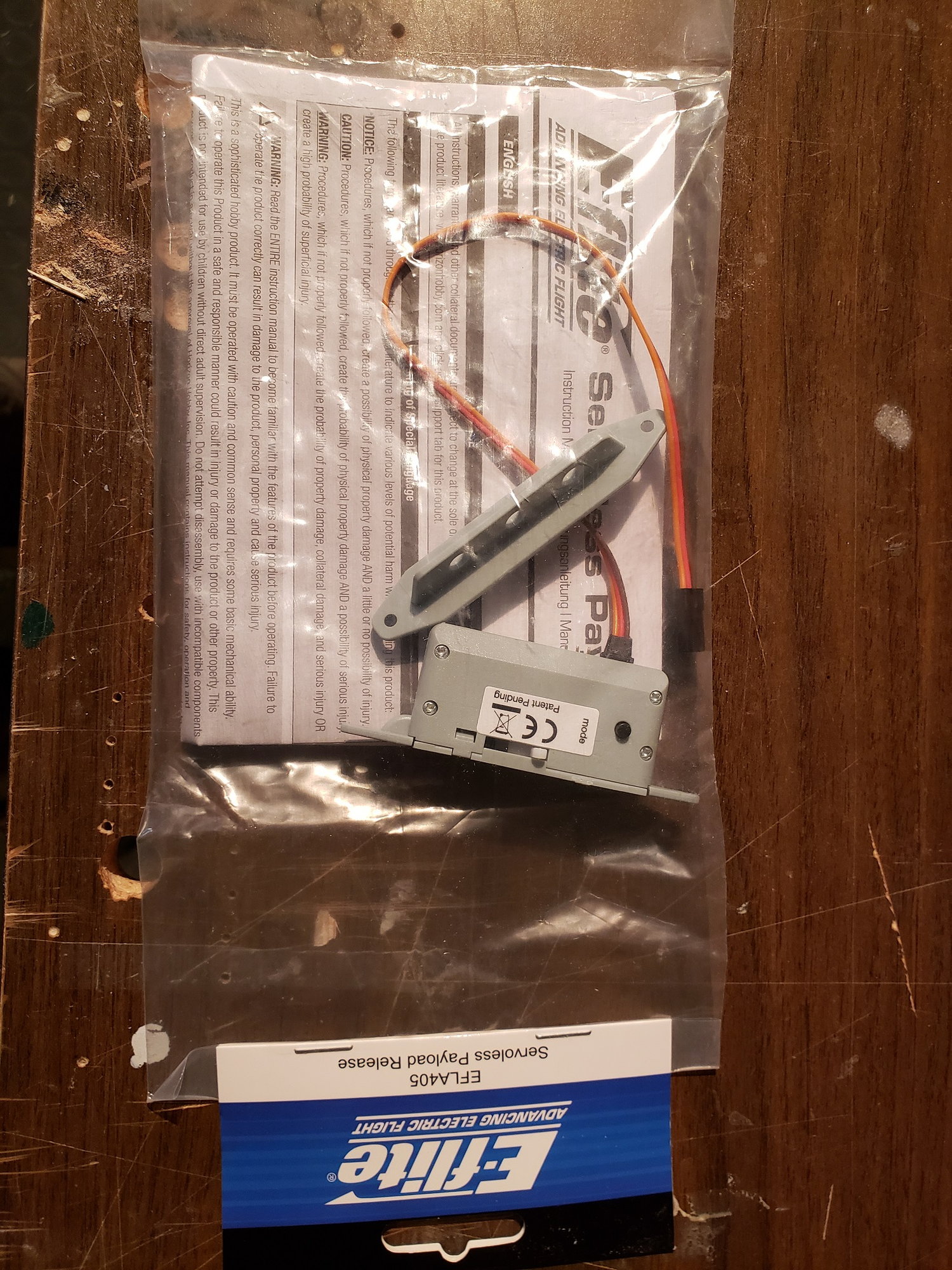
I had originally planned to use E-flight payload release devices, as they work great on my Corsair. But the hardpoints are directly under the aluminum tube. So these are not going to fit.
10-20-2021, 05:09 AM
#118
Senior Member
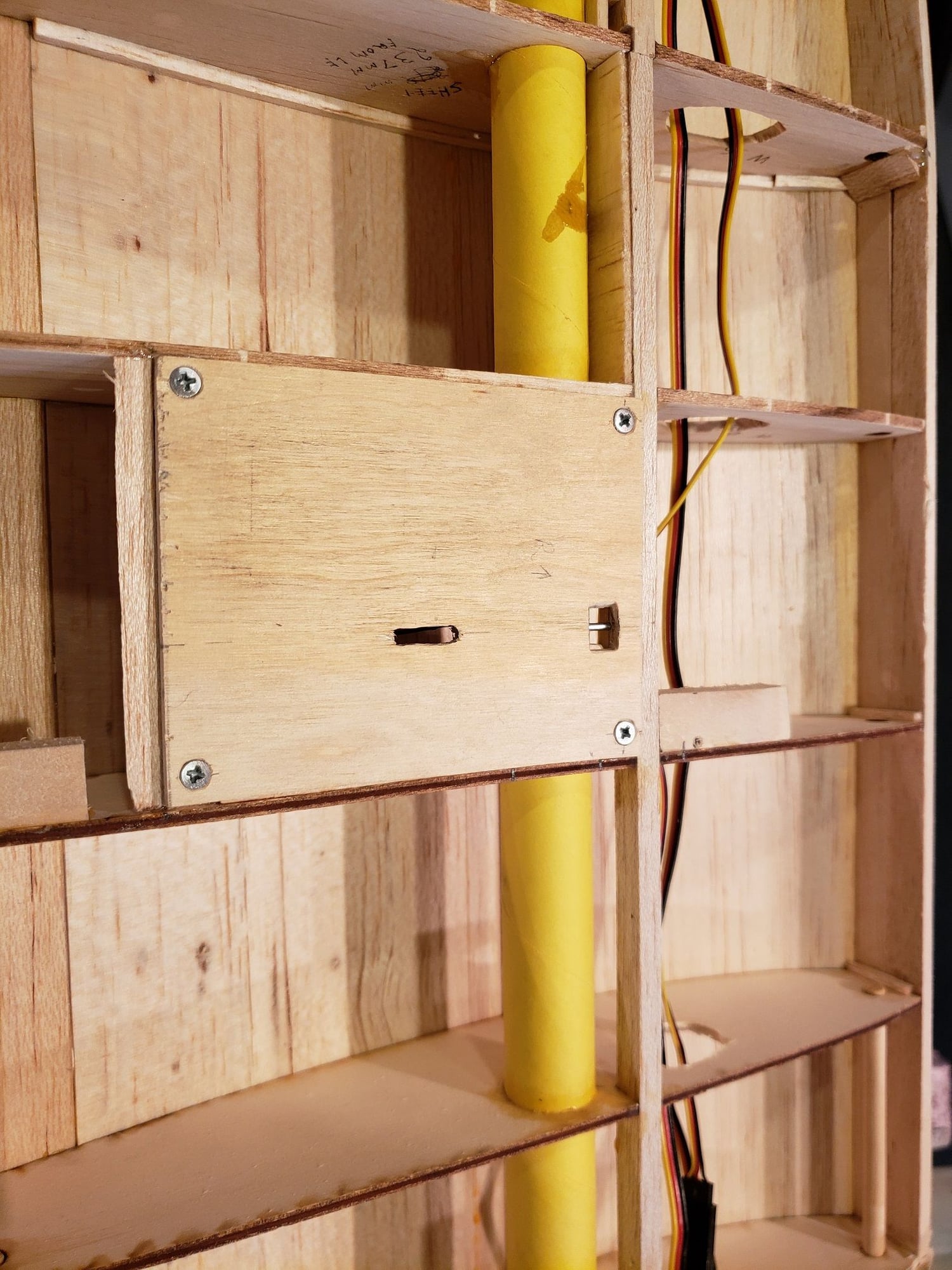
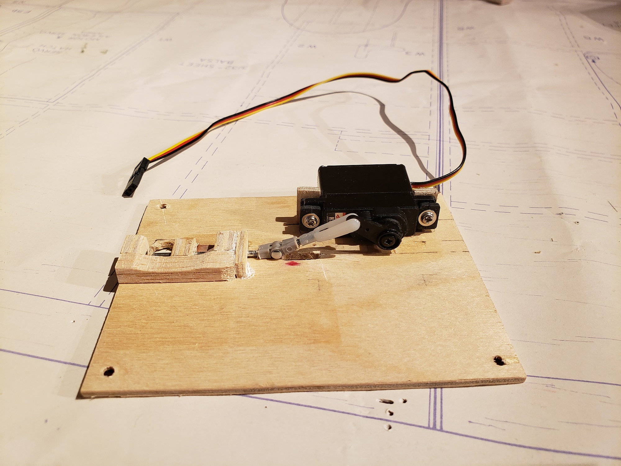
I built my own payload release devices that will fit in the 1/4" space under the aluminum tube. Here's the one for the right wing.
The servo horn has a slot cut in it that the clevis can travel up and down in as the servo arm rotates back and forth.
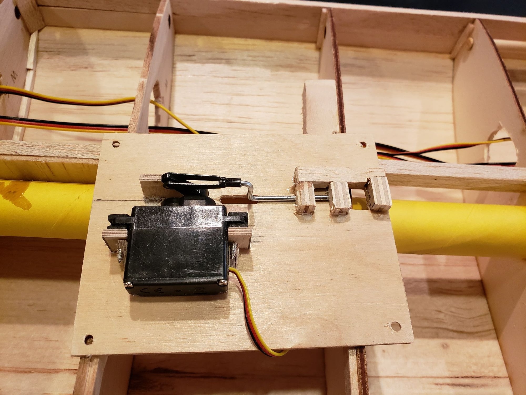
The servo horn has a slot cut in it that the clevis can travel up and down in as the servo arm rotates back and forth.
10-20-2021, 05:14 AM
#119
Senior Member
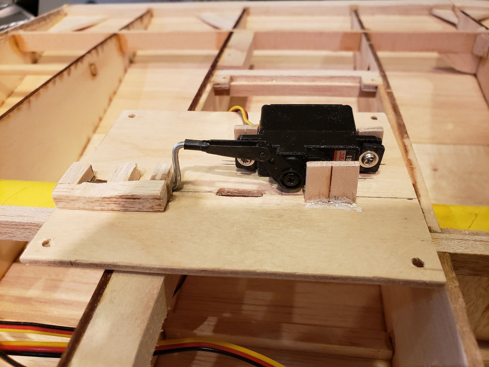
The device for the left wing is a slightly different mechanism. The 2 have different travels. This will allow me to drop one side and then the other using one channel. Half way through the movement the left side will drop and at the full movement the right side will drop. Set up on a 3 position switch. And of course, if you just pull the switch through both positions the 2 sides drop at virtually the same time.
The following users liked this post:
scottrc (10-20-2021)
10-30-2021, 06:39 PM
#122
Senior Member
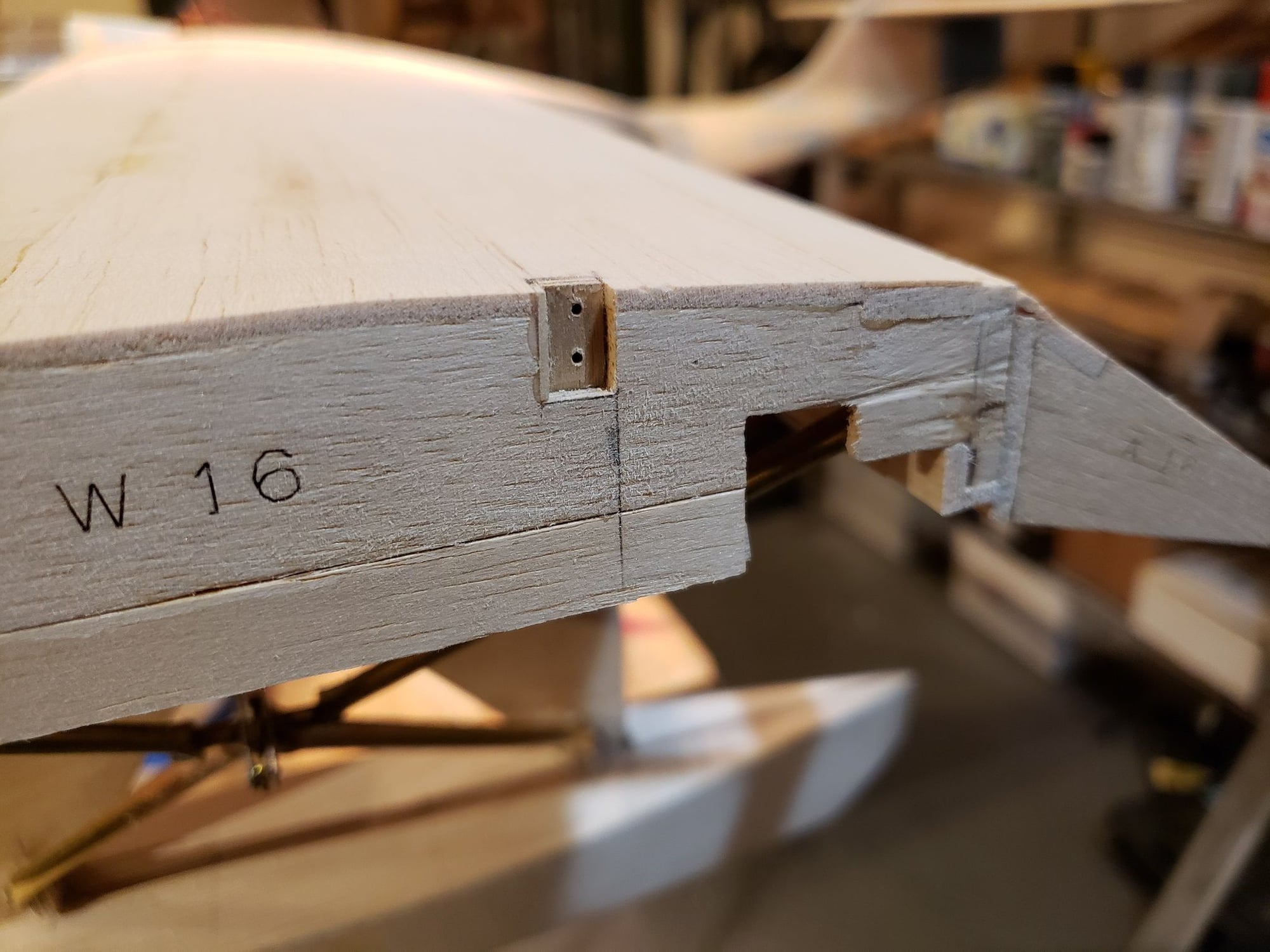
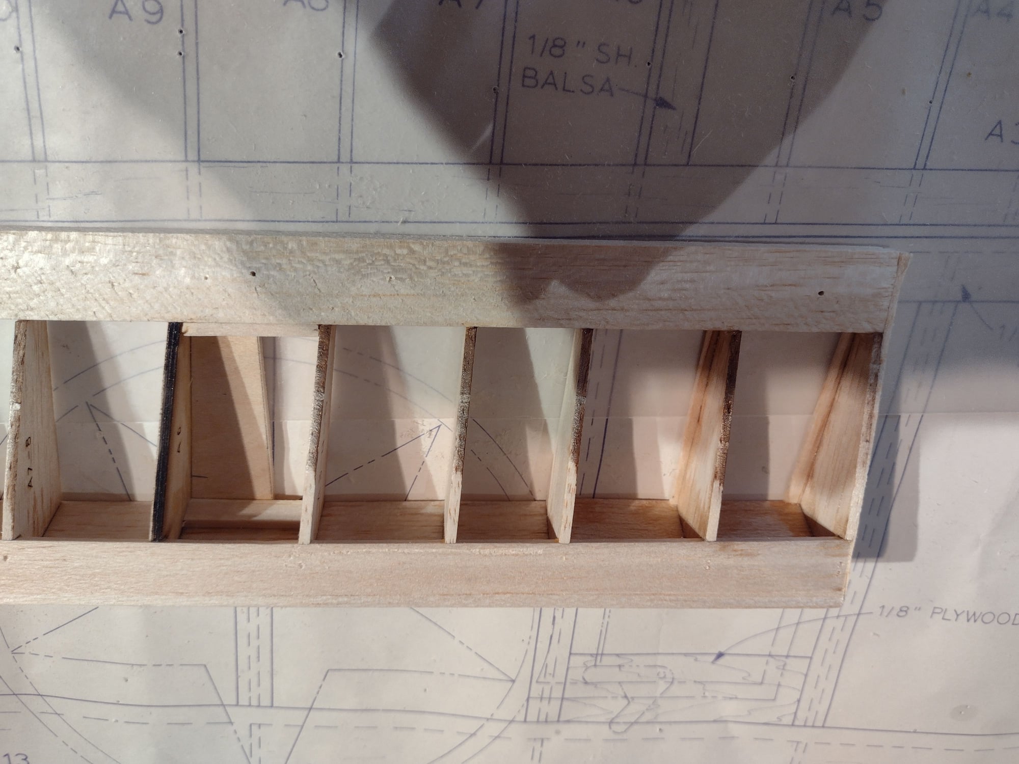
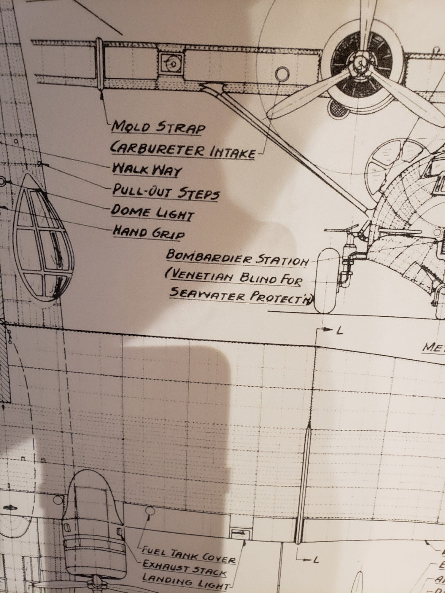
If you look at the photo below, there is a fairing of some kind at the mid span of each wing. It's labeled "Mold Strap". If anyone has insight on why this was needed, would like to know.
You can see that is only covers the aluminum part of the wing chord wise. It's large enough to be noticed, so I'll have to make something.
You can see that is only covers the aluminum part of the wing chord wise. It's large enough to be noticed, so I'll have to make something.
10-30-2021, 06:47 PM
#123
Senior Member
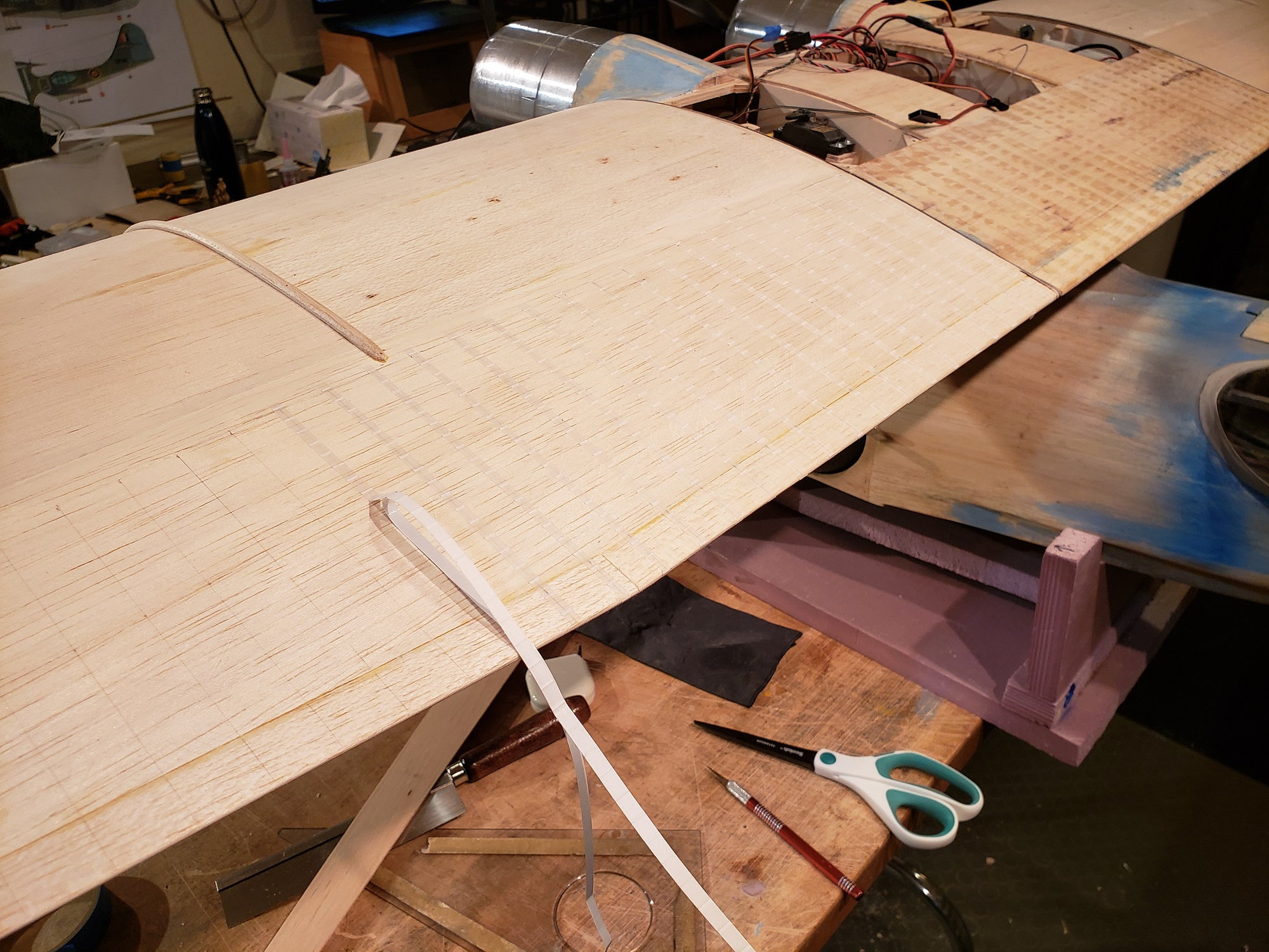
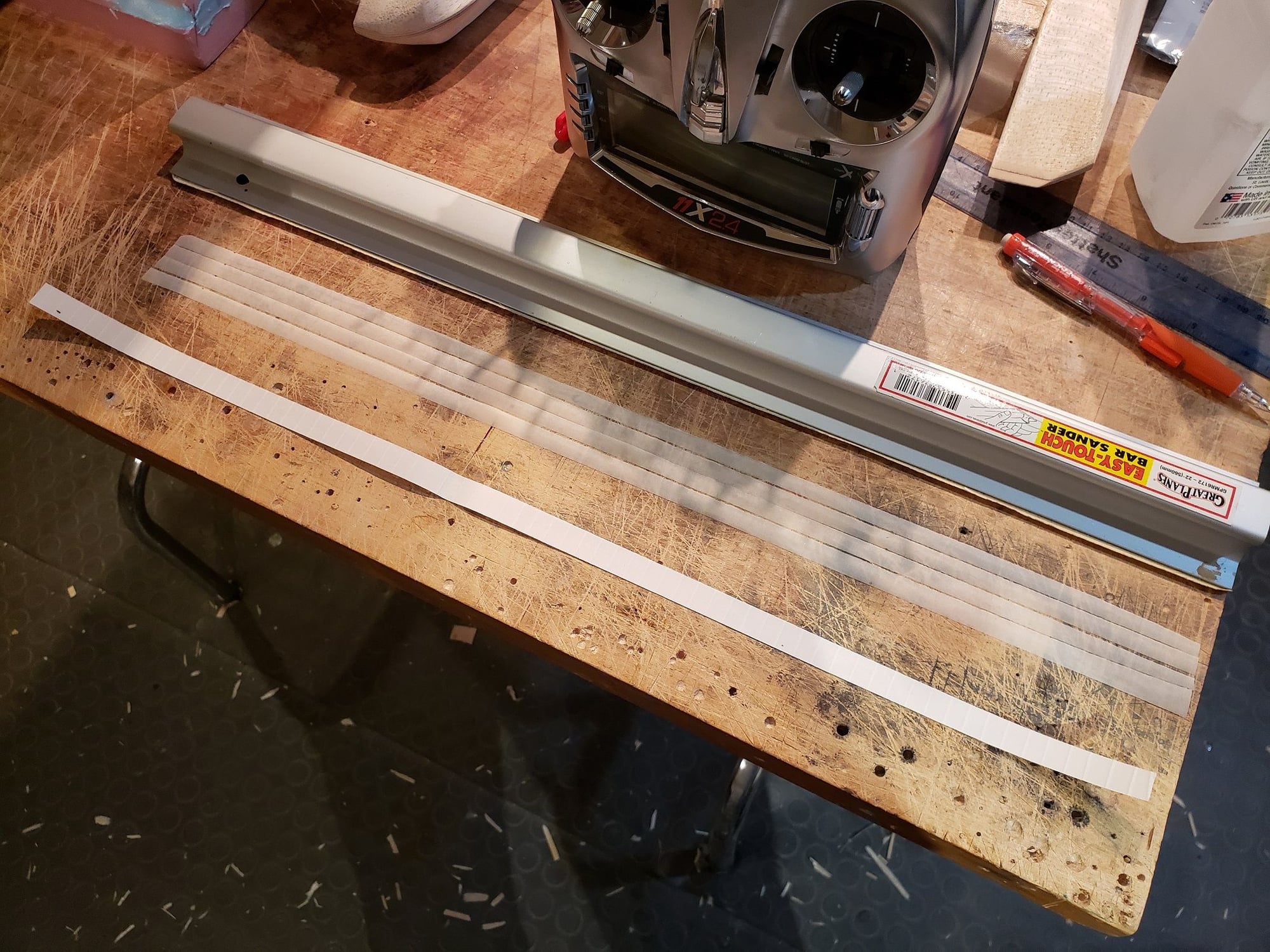
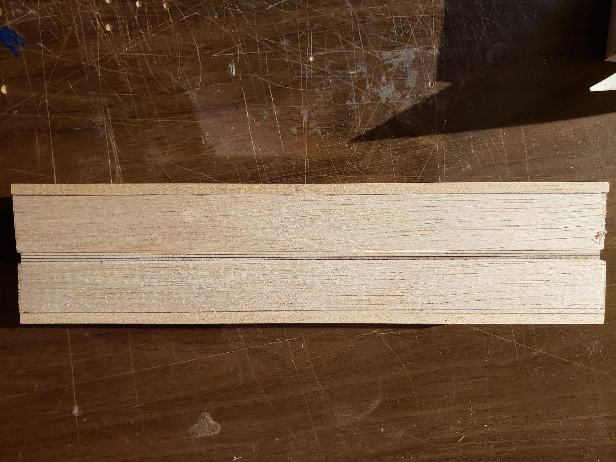
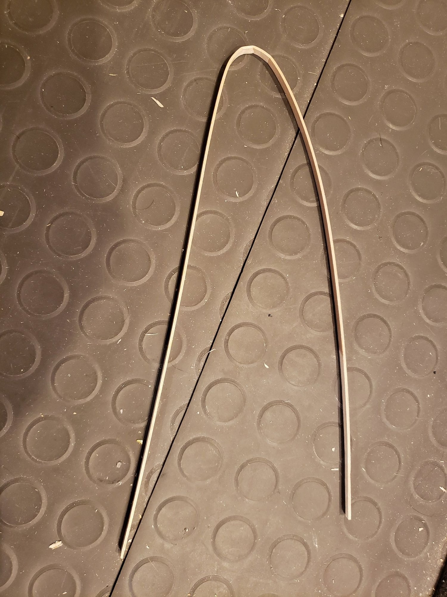
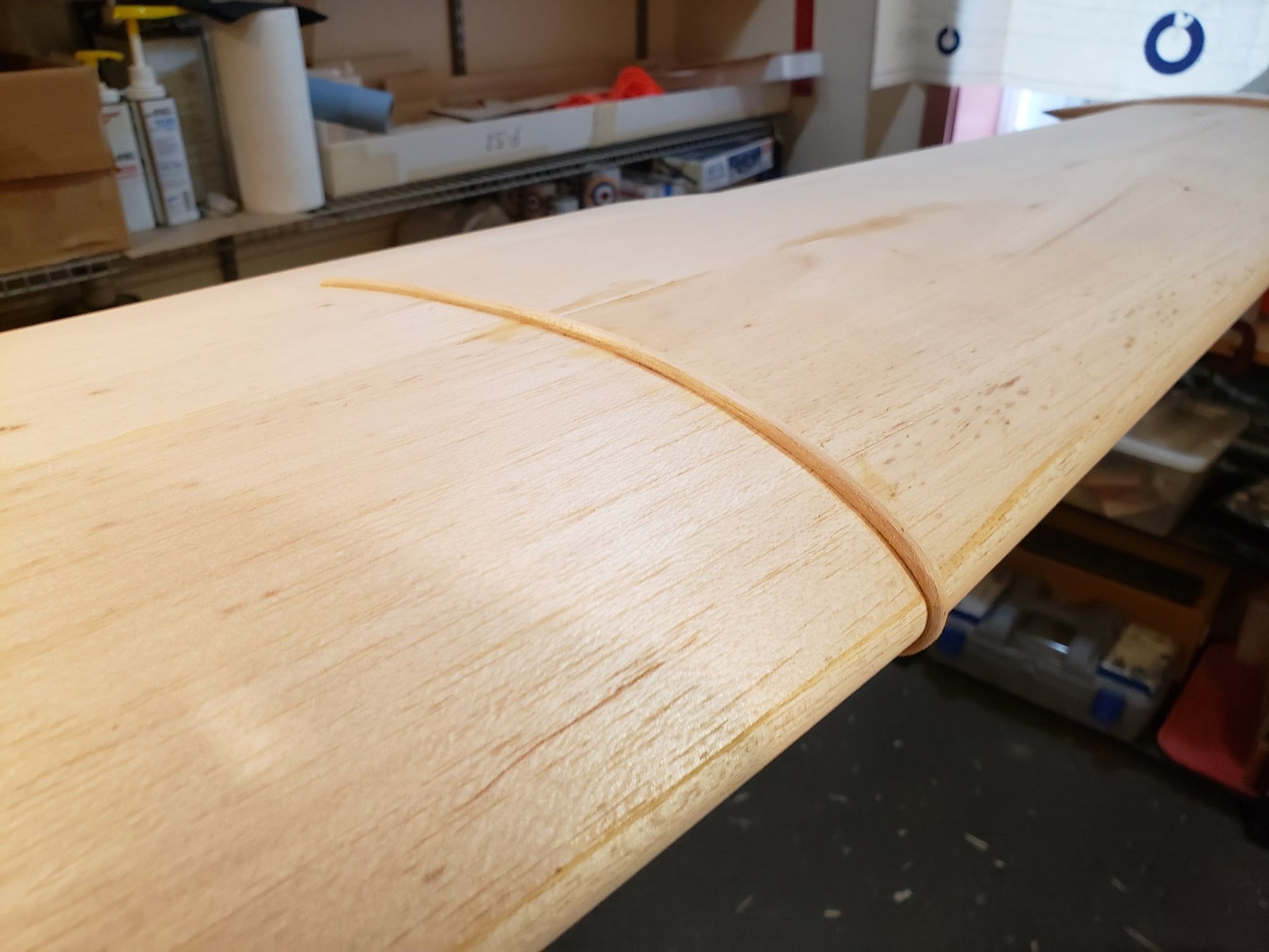
I will make the part out of 2 strips of 1/16" x 1/4" balsa. These will be steamed and bent to shape. Then they will be laminated together to form a 1/8" x 1/4" part.
Here's the part after steaming and putting a basic bend in it.
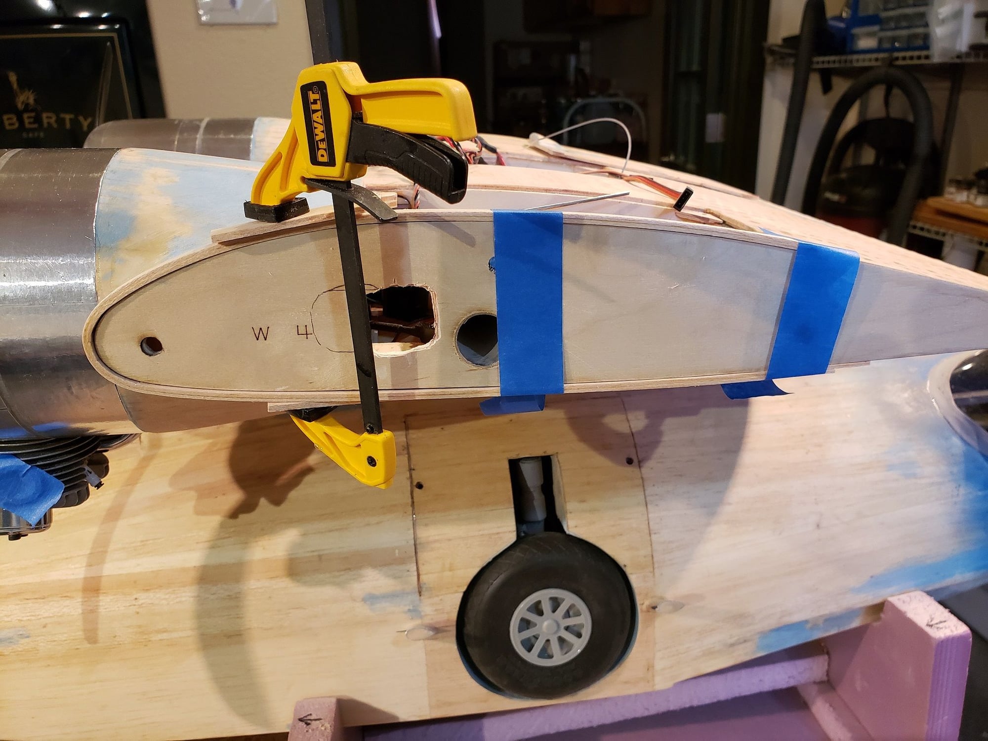
Here, 2 are being glued together, wetted, and clamped to the wing to get the right shape.
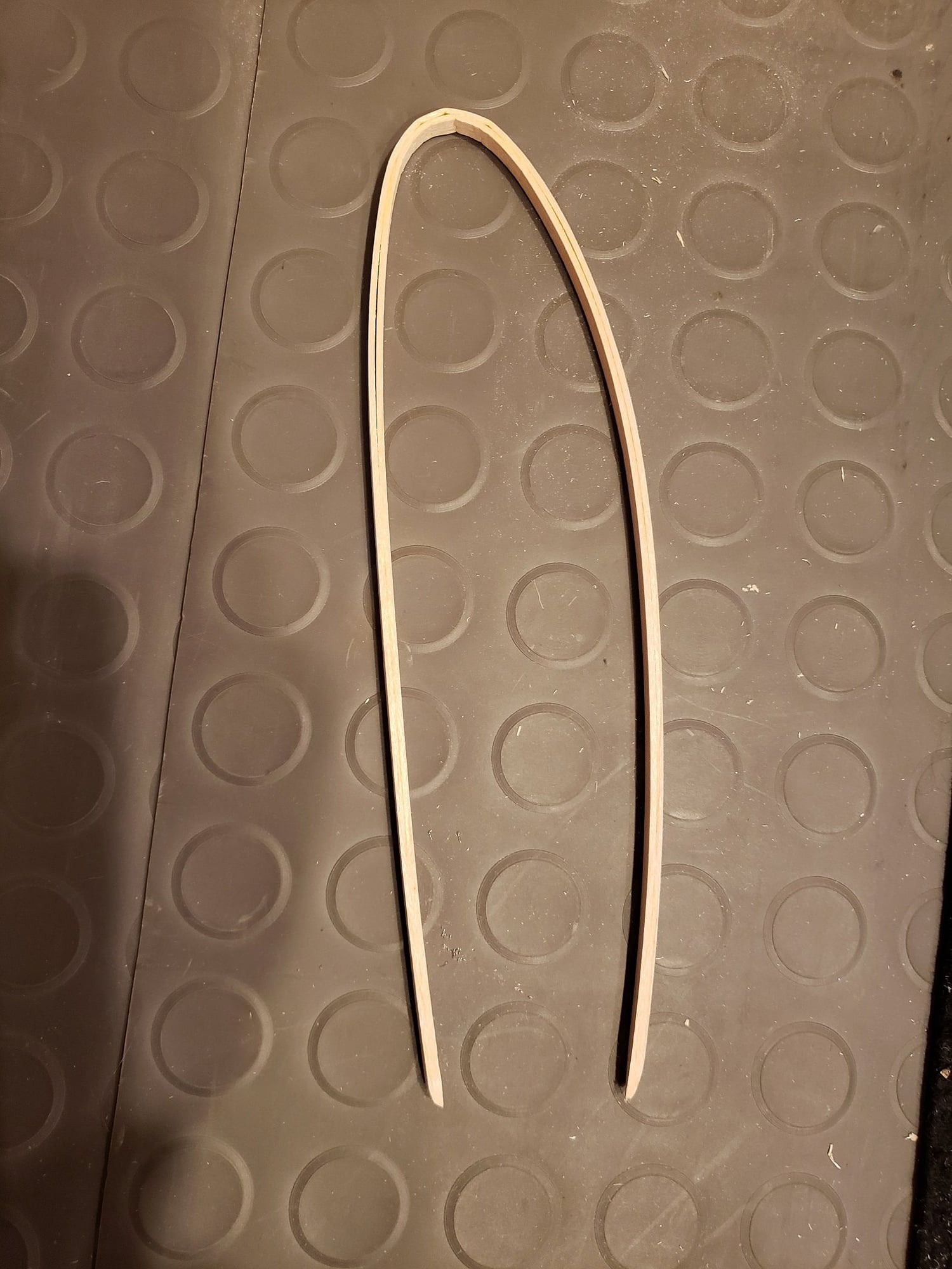
The part once fully formed.
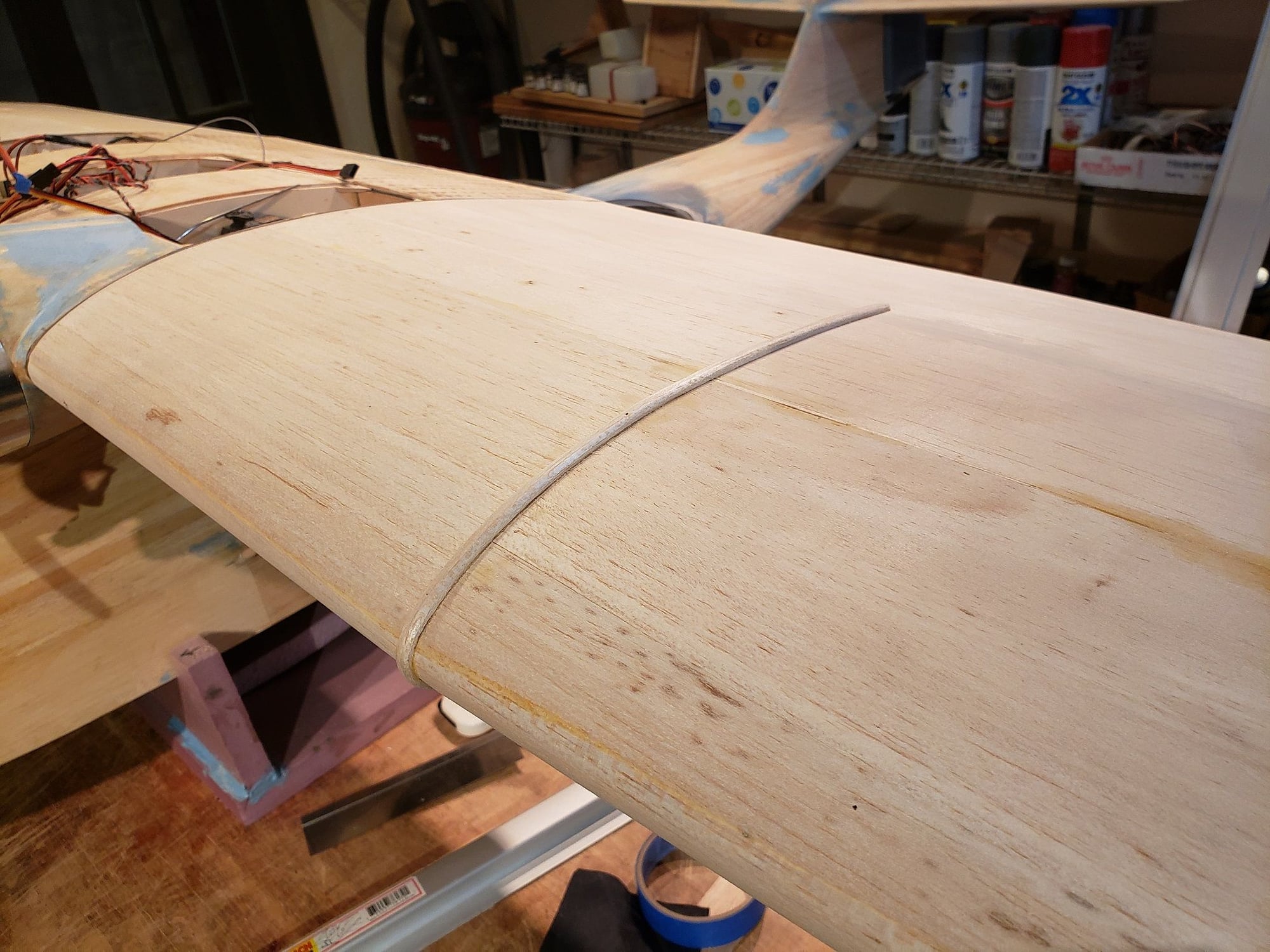
Installed.
Here's the part after steaming and putting a basic bend in it.
Here, 2 are being glued together, wetted, and clamped to the wing to get the right shape.
The part once fully formed.
Installed.
11-17-2021, 07:10 PM
#124
Senior Member
At the end of each wing tip there is an antenna mast. The antenna itself is routed out the fuse ahead of the wing, up the LE of the wing, over the top, to the vert stab and then splits left and right running to each wing tip. I plan to have the antenna on the plane. Here are the masts.