


Ziroli f4u corsair build.
 06-07-2020, 08:05 AM
#1

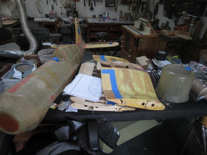
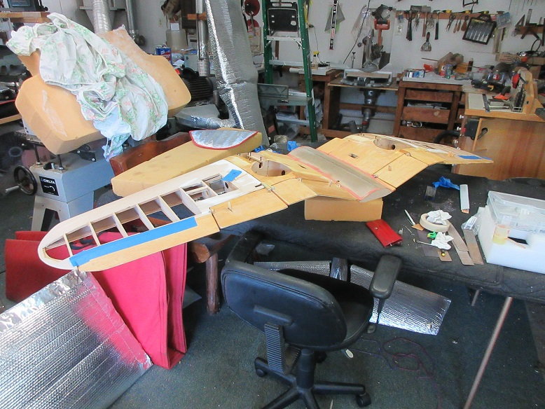
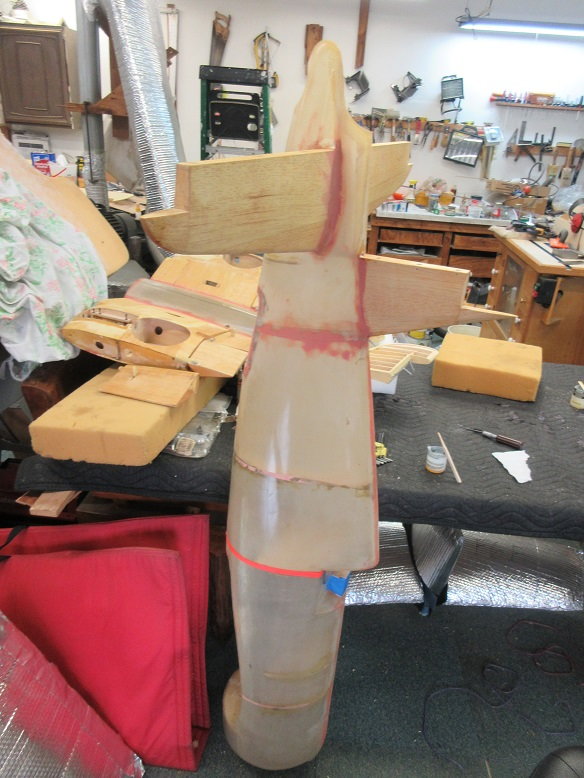
A few years ago, I bought this Corsair in the 'bones' and thought I'd finish it.
Usually, I like building from scratch but it appeared the builder did a pretty good job of building it and the price was real good!
I'm not going 'anal' on this plane: no functional main/tail wheel doors, full cockpit detail, functioning canopy, cowl flaps and hidden switches.
Just a basic plane to take to the field.
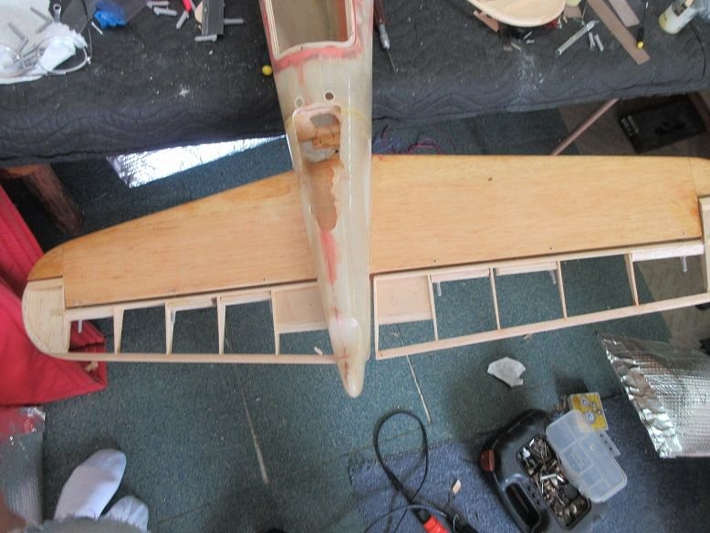
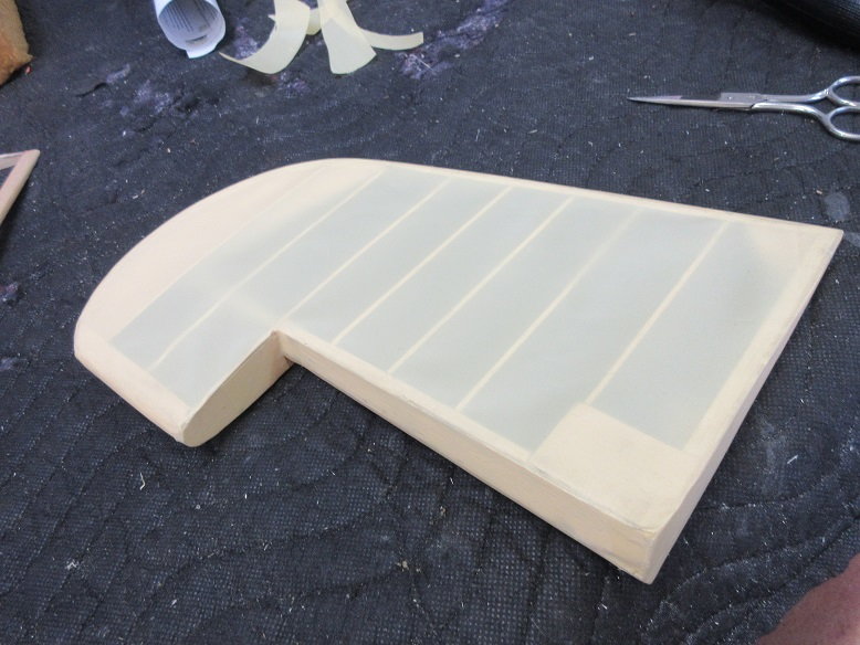
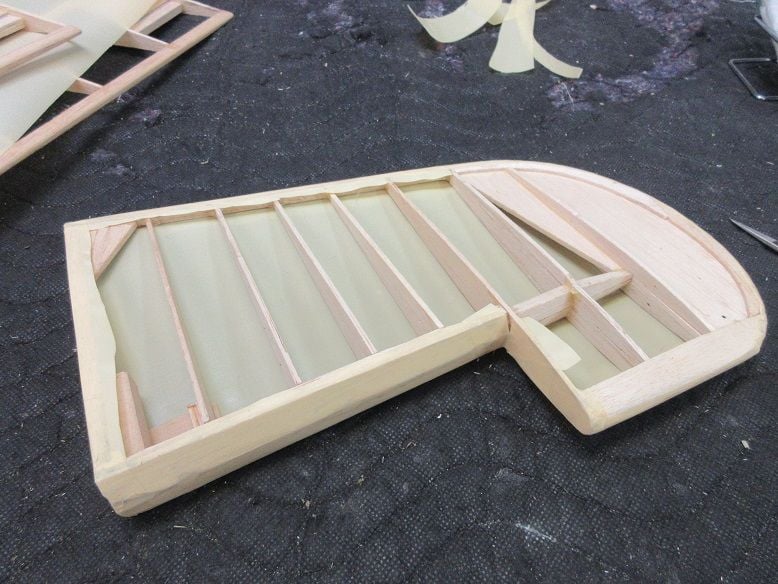
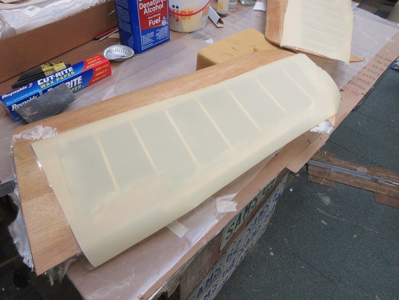
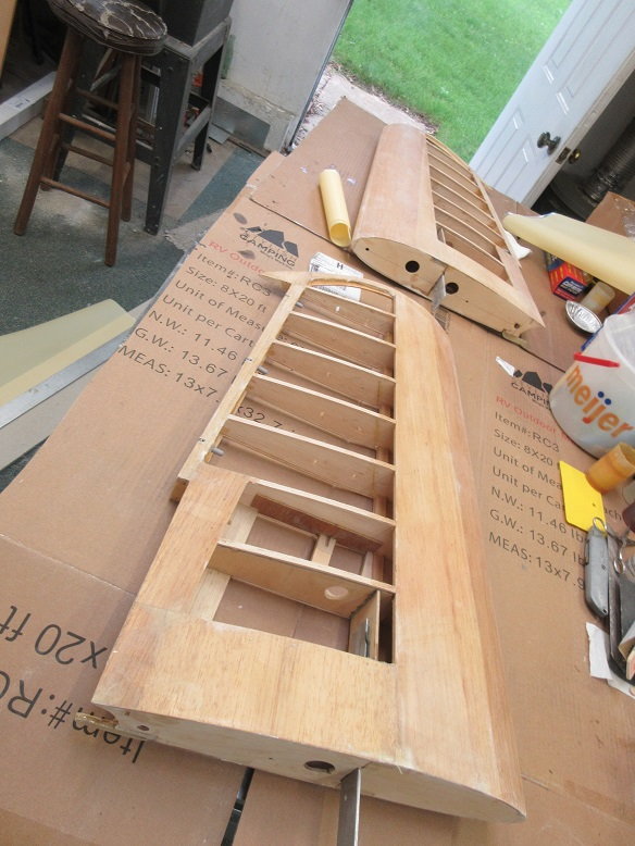
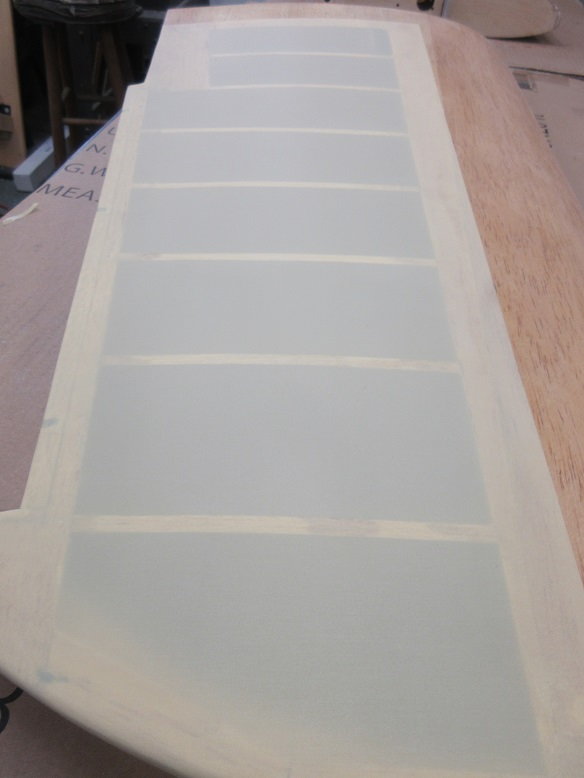
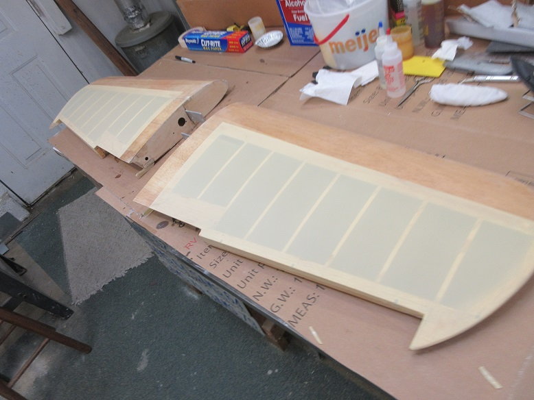
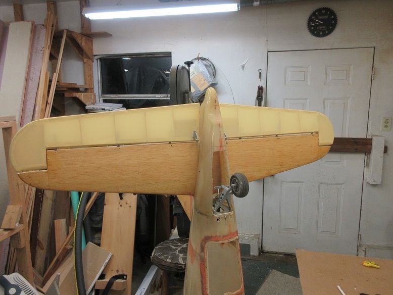
This plane has the FG fuse. Previous builder glassed the inner wing. I plan to use Solartex on the two outer wings to give the cloth affect for the ribs as on the prototype.
No sierra gear. Just a set of Robart gear that I picked up last fall when they had a sale. I do have some aluminum hub wheels, though (already in my 'hobby shop').
Tower had a good discount coupon so I picked up a DLE-85 for it: should be plenty of power since it should be pretty light without all the extra 'crap' that I, usually, add.

Nice that the original builder replaced the garbage lite ply with aircraft ply on his build.
Ziroli plans and instructions specifically say to use aircraft ply for certain parts.
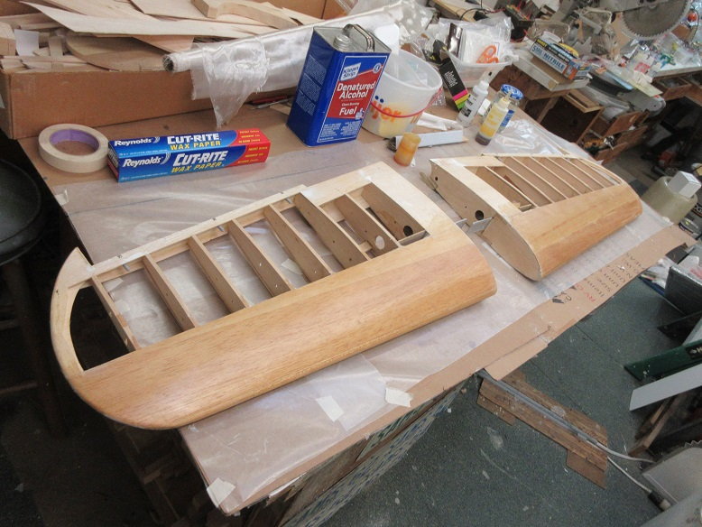
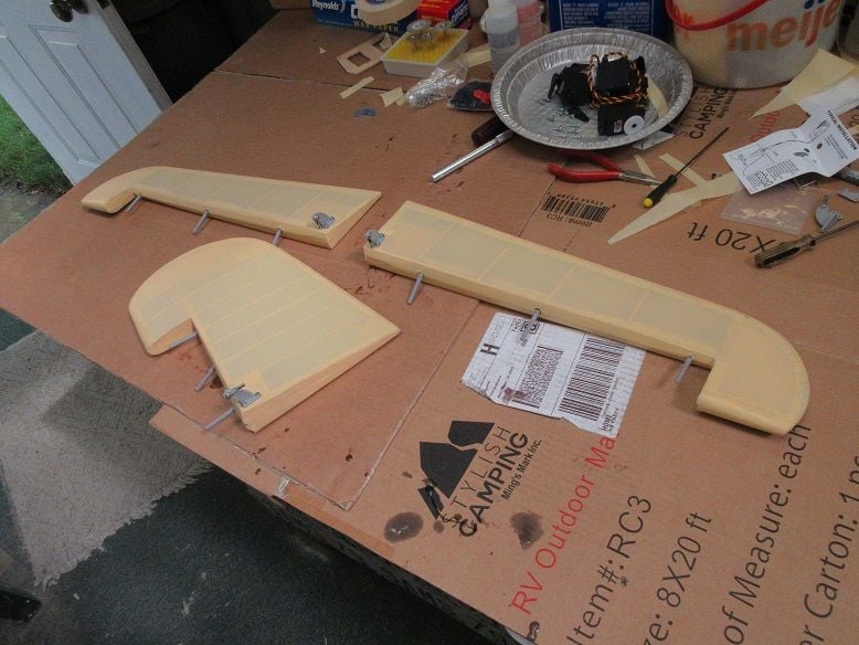
Thought that I'd start with the hard part first: getting the flaps to function smoothly.
For some reason though, he use lite ply on the outside hinges for the inner wing section for the flaps so those are getting replaced.

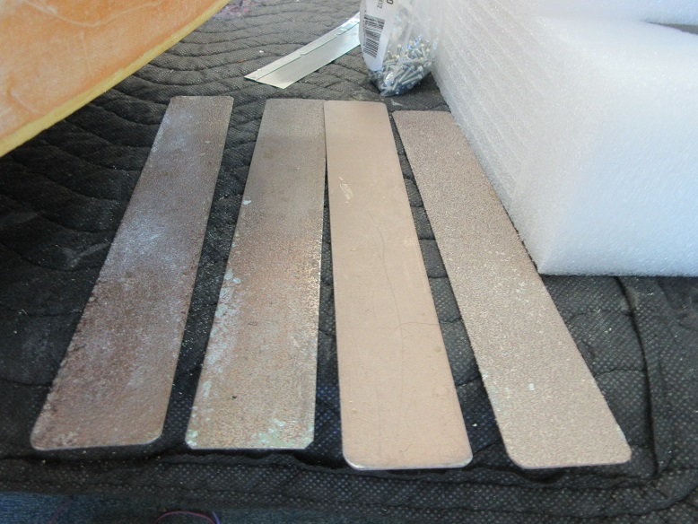
Some G-10 is being used for the flap hinge replacements.
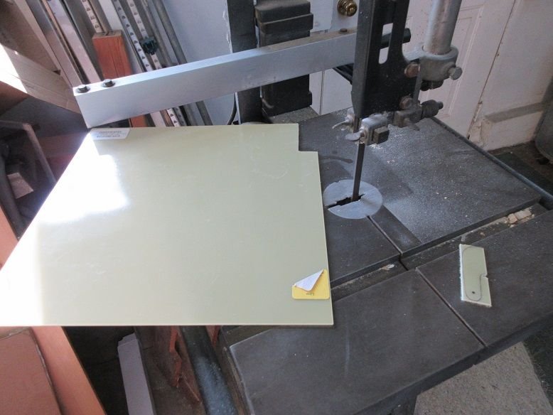
Can only get so close on using a band saw to cut the G-10. G-10 is very hard on blades.
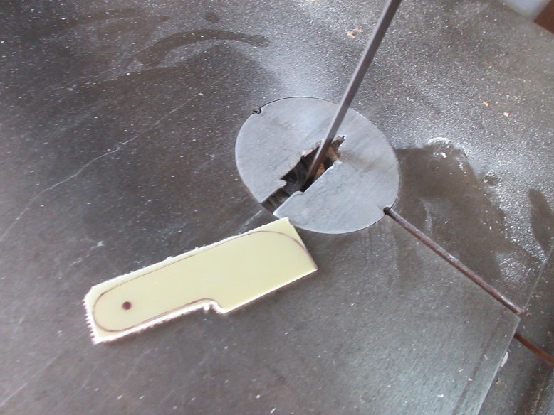
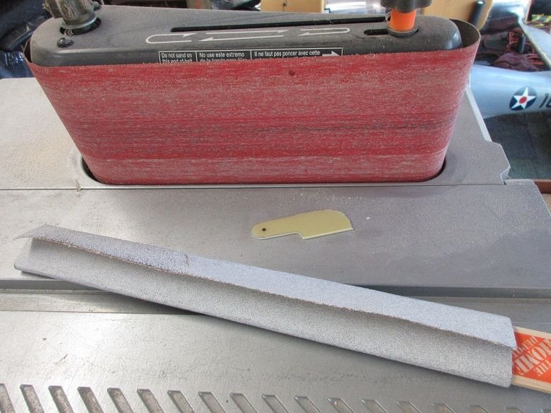
The final finish of the flap hinge is done with an oscillating sander and some 100 grit wrapped on a paint stick.
Some thin metal impregnated with diamonds cut off disks are used to remove the old wood flap hinges.
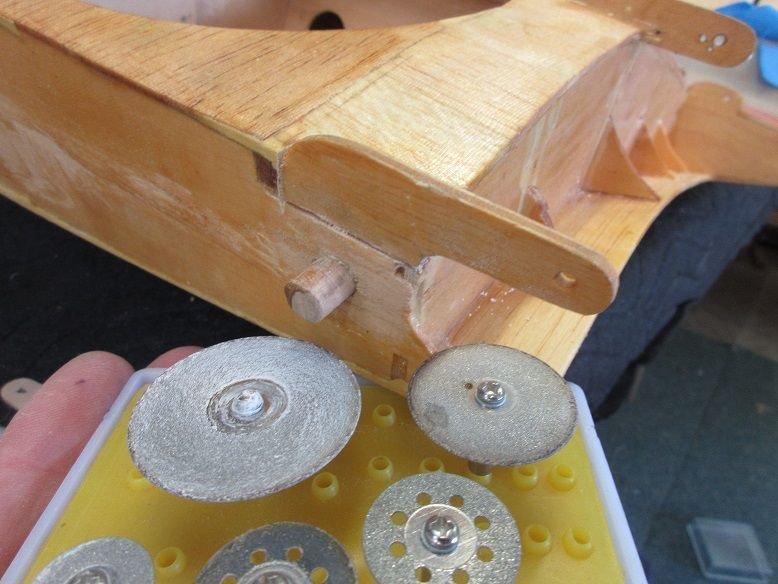
A total of 4 flap hinges need to be replaced. I made one ply hinge for a 'master'.
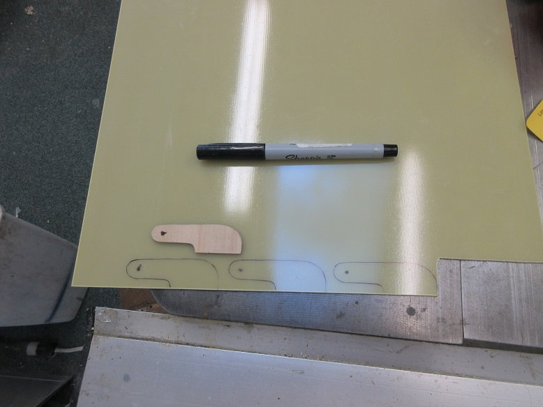
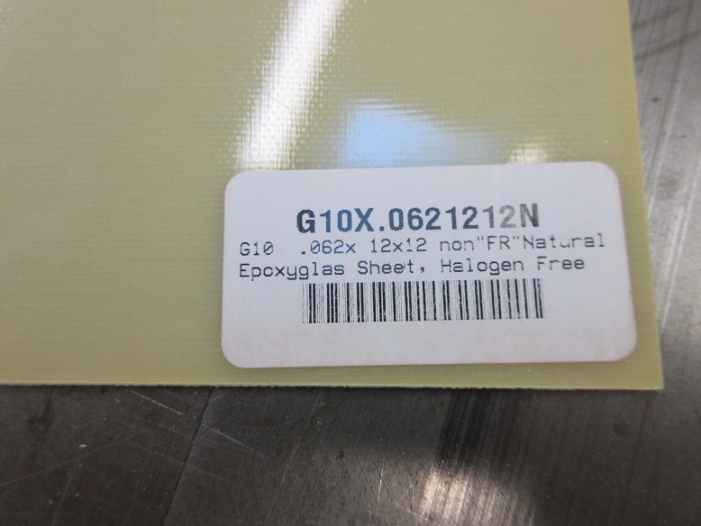
Used about 3/32" thick G-10. I got the G-10 from Frank Tiano but micromark sells it also.
The bottom of the new hinge need some material removed for free movement of the flap.
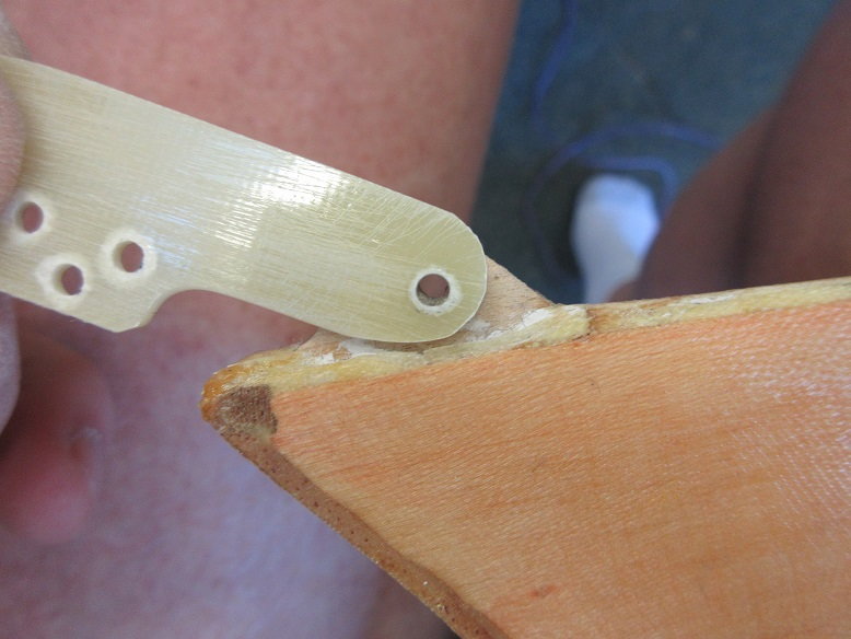
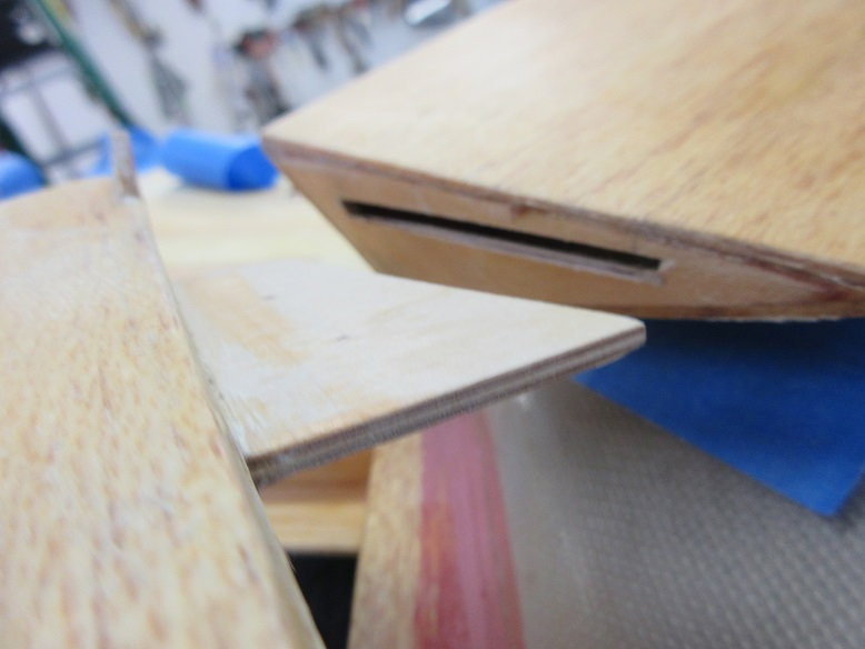
Corsair flaps can be tricky to operated smoothly since each side has 3 flaps. To get the ply to, easily, slide into the flap next to it, an angle was sanded on each side of the slot.
These metal sanders are great as they can get into tight spaces and leaves a nice straight line. Got these from Bob Violet jets.
For some reason, there was no hinge on the inner flap. I'm guessing that the builder may have thought the ply that slides into the flap would hold it in place.
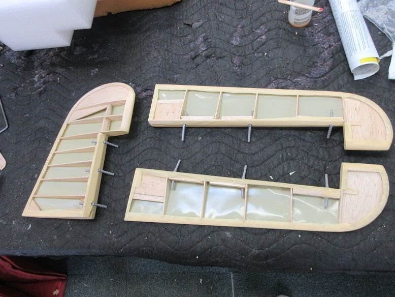
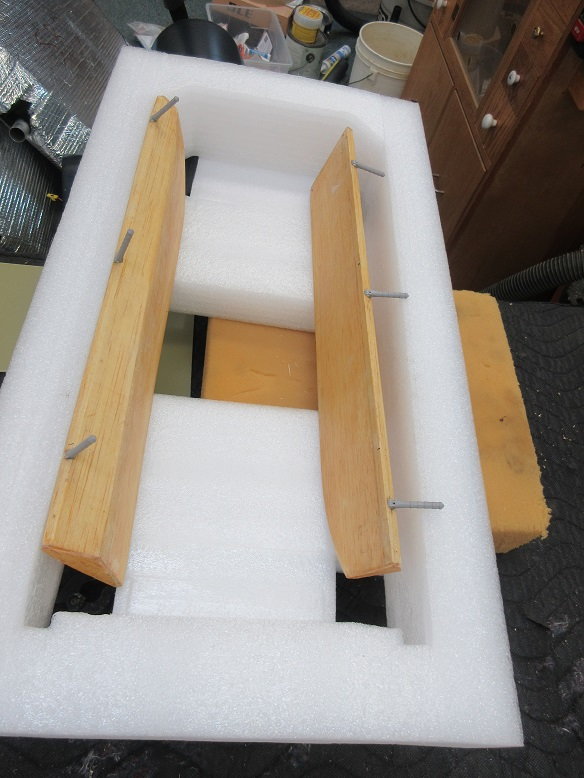
Some more G-10 used to make a new flap hinge. 4/40 bolts and nuts are used to secure the flaps to the wings. Everything is made modular for ease of painting and PM.

Flaps are working well. UP position.
About 45 degrees down should be good enough.

Drilled some holes where the new G-10 hinge will be to give the epoxy some 'tooth'.
Usually, I like building from scratch but it appeared the builder did a pretty good job of building it and the price was real good!
I'm not going 'anal' on this plane: no functional main/tail wheel doors, full cockpit detail, functioning canopy, cowl flaps and hidden switches.
Just a basic plane to take to the field.
This plane has the FG fuse. Previous builder glassed the inner wing. I plan to use Solartex on the two outer wings to give the cloth affect for the ribs as on the prototype.
No sierra gear. Just a set of Robart gear that I picked up last fall when they had a sale. I do have some aluminum hub wheels, though (already in my 'hobby shop').
Tower had a good discount coupon so I picked up a DLE-85 for it: should be plenty of power since it should be pretty light without all the extra 'crap' that I, usually, add.
Nice that the original builder replaced the garbage lite ply with aircraft ply on his build.
Ziroli plans and instructions specifically say to use aircraft ply for certain parts.
Thought that I'd start with the hard part first: getting the flaps to function smoothly.
For some reason though, he use lite ply on the outside hinges for the inner wing section for the flaps so those are getting replaced.
Some G-10 is being used for the flap hinge replacements.
Can only get so close on using a band saw to cut the G-10. G-10 is very hard on blades.
The final finish of the flap hinge is done with an oscillating sander and some 100 grit wrapped on a paint stick.
Some thin metal impregnated with diamonds cut off disks are used to remove the old wood flap hinges.
A total of 4 flap hinges need to be replaced. I made one ply hinge for a 'master'.
Used about 3/32" thick G-10. I got the G-10 from Frank Tiano but micromark sells it also.
The bottom of the new hinge need some material removed for free movement of the flap.
Corsair flaps can be tricky to operated smoothly since each side has 3 flaps. To get the ply to, easily, slide into the flap next to it, an angle was sanded on each side of the slot.
These metal sanders are great as they can get into tight spaces and leaves a nice straight line. Got these from Bob Violet jets.
For some reason, there was no hinge on the inner flap. I'm guessing that the builder may have thought the ply that slides into the flap would hold it in place.
Some more G-10 used to make a new flap hinge. 4/40 bolts and nuts are used to secure the flaps to the wings. Everything is made modular for ease of painting and PM.
Flaps are working well. UP position.
About 45 degrees down should be good enough.
Drilled some holes where the new G-10 hinge will be to give the epoxy some 'tooth'.
Last edited by samparfitt; 06-07-2020 at 04:21 PM.
 06-07-2020, 04:14 PM
#2
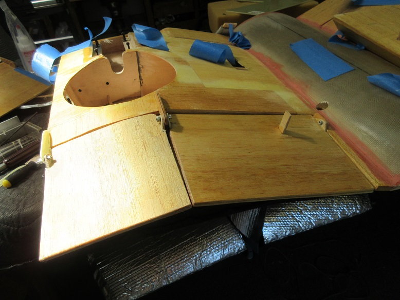
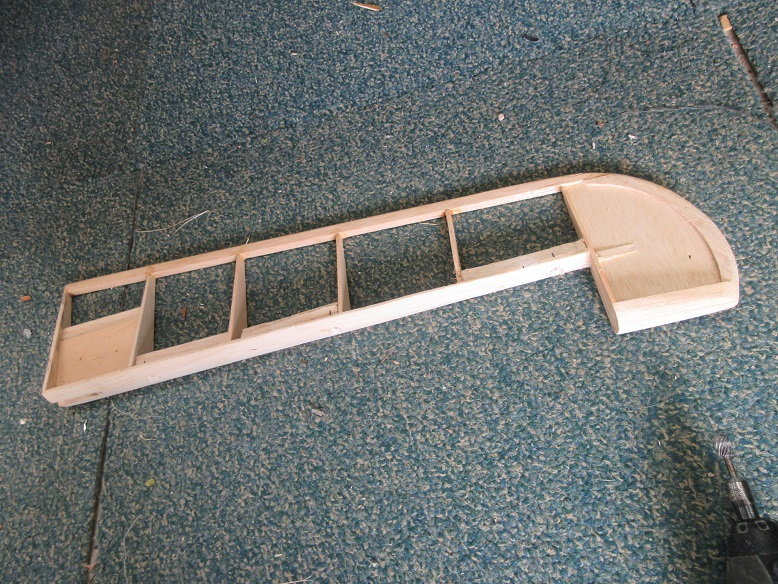
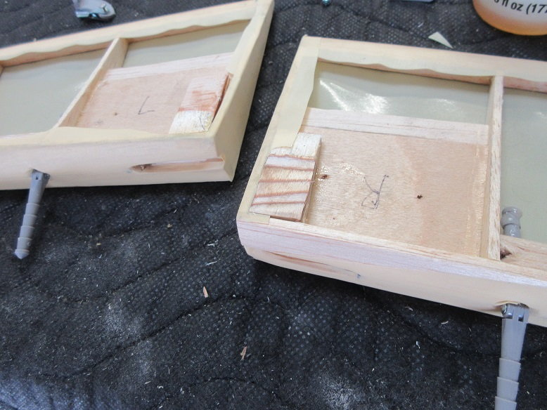
Wing, flaps (cont)
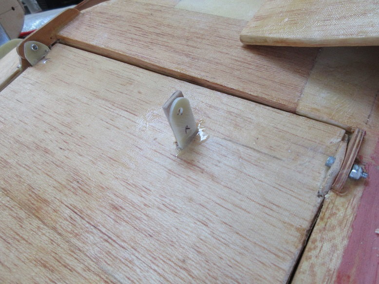
Left side:
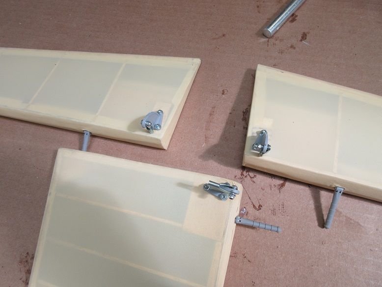
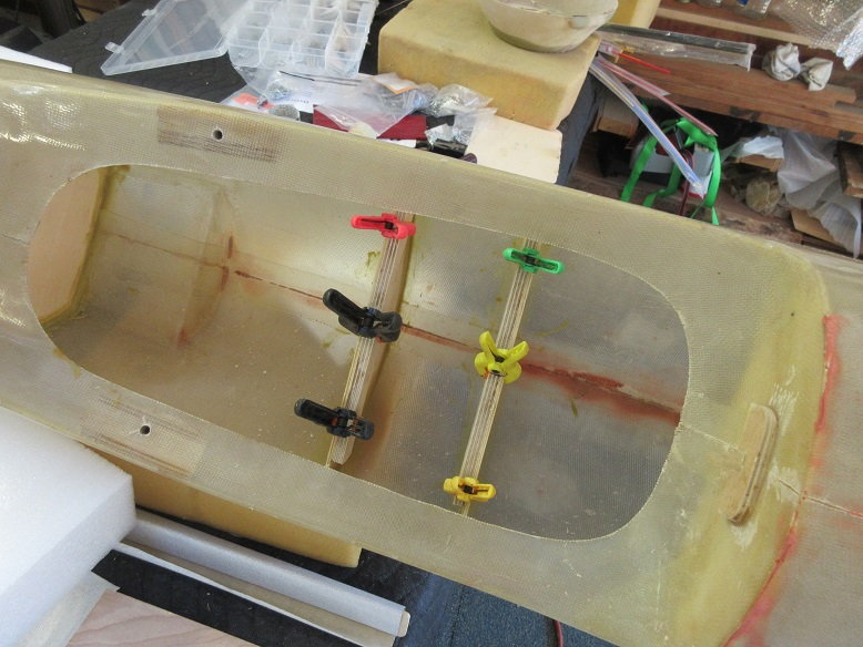
The inner flap needed a spacer (G-10) to prevent the flap from rubbing the wing.

Inner flap done.
4/40 with locking nuts.
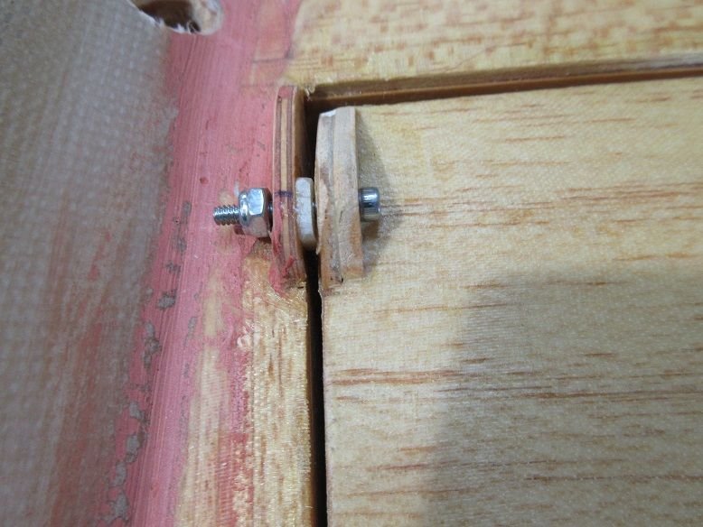
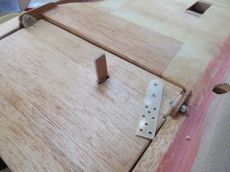
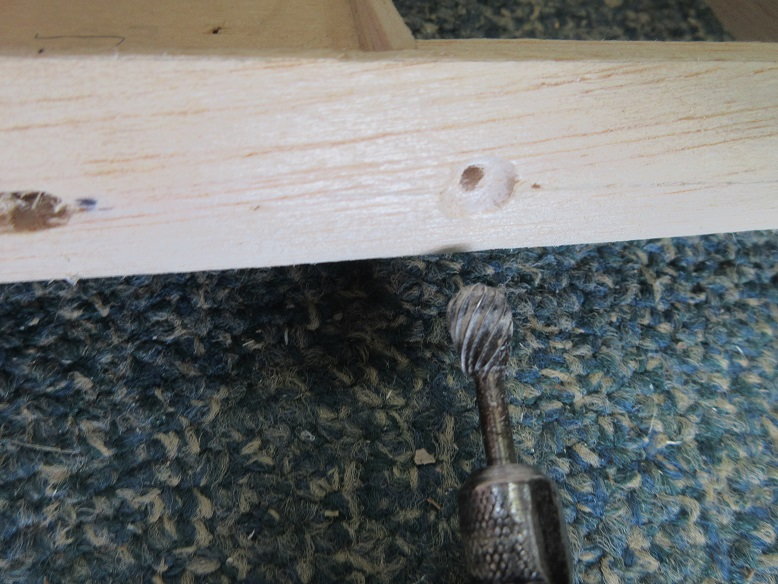
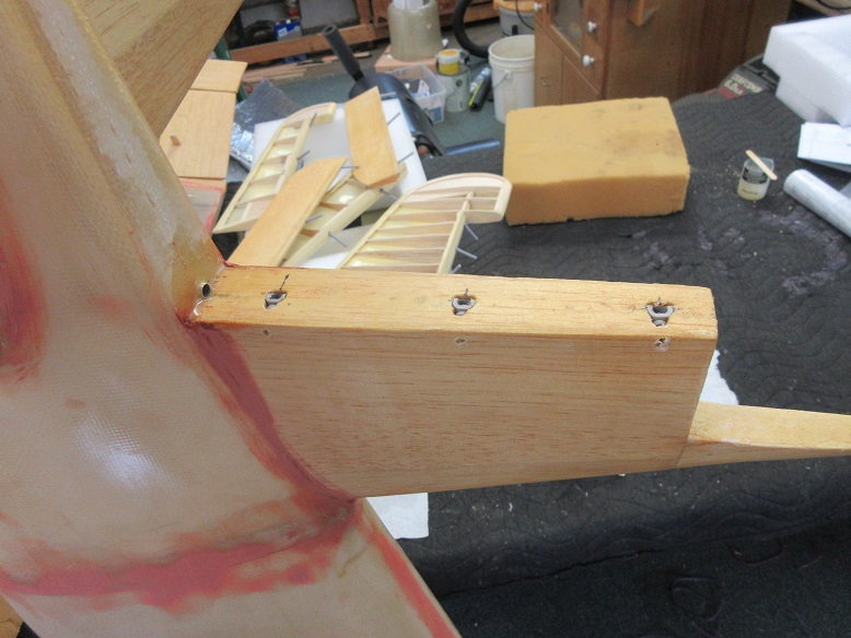
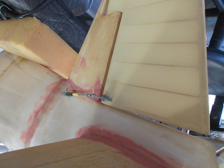
Right side:
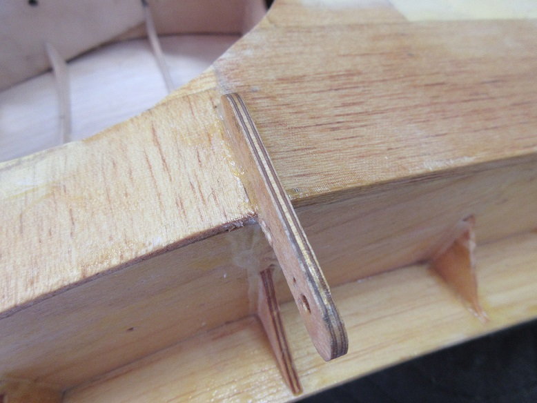
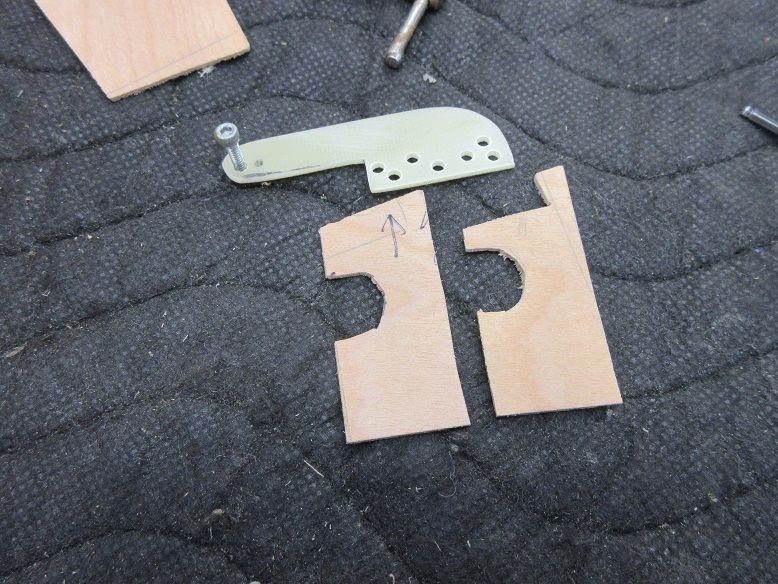
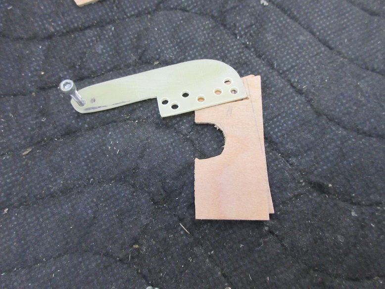
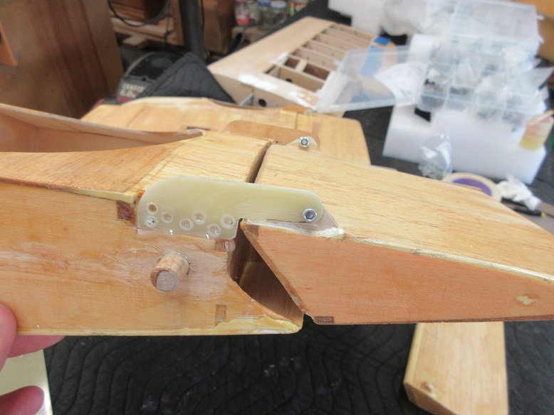
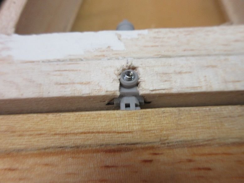
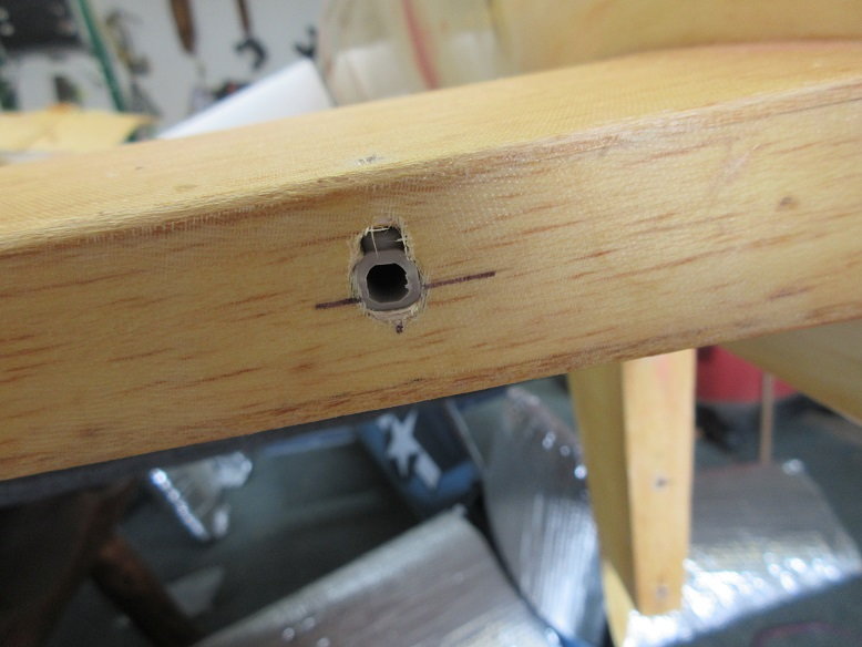
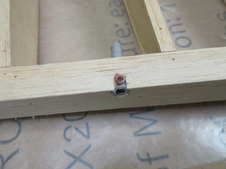
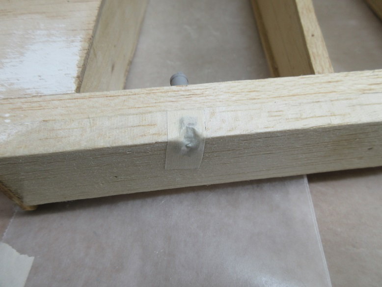
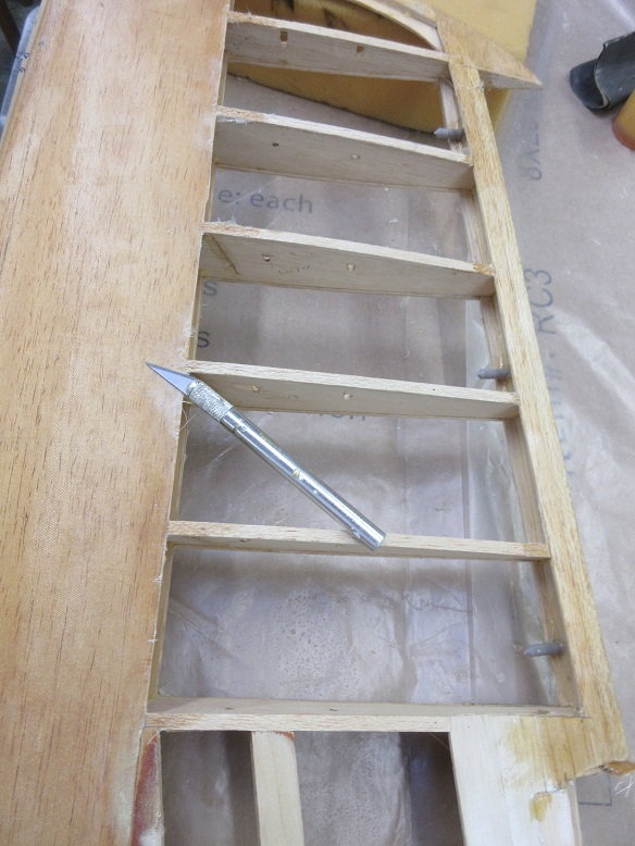
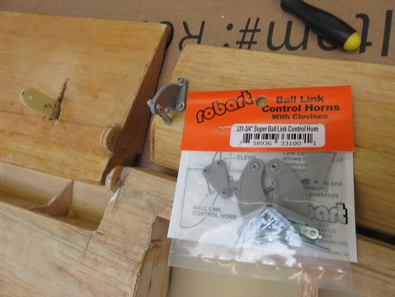
I think this control horn is the original builder's idea as, usually, Ziroli's flaps are linked internally and on the LE of the flap. Anyway, since I don't know what internal blockage he did I'll use what he set up.
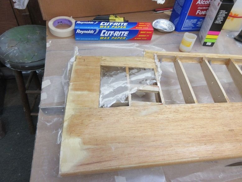
The ply is a little thin so it is re-enforced with some G-10. I stuck a pin on both sides of the ply to find out where the rib was and cut a slot on the opposite side.
Slop some epoxy on and it should be good 'to go'.
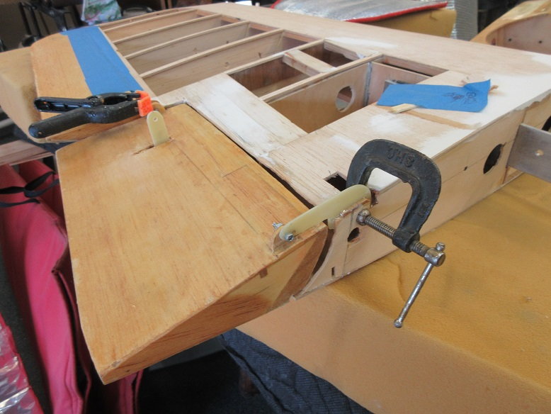
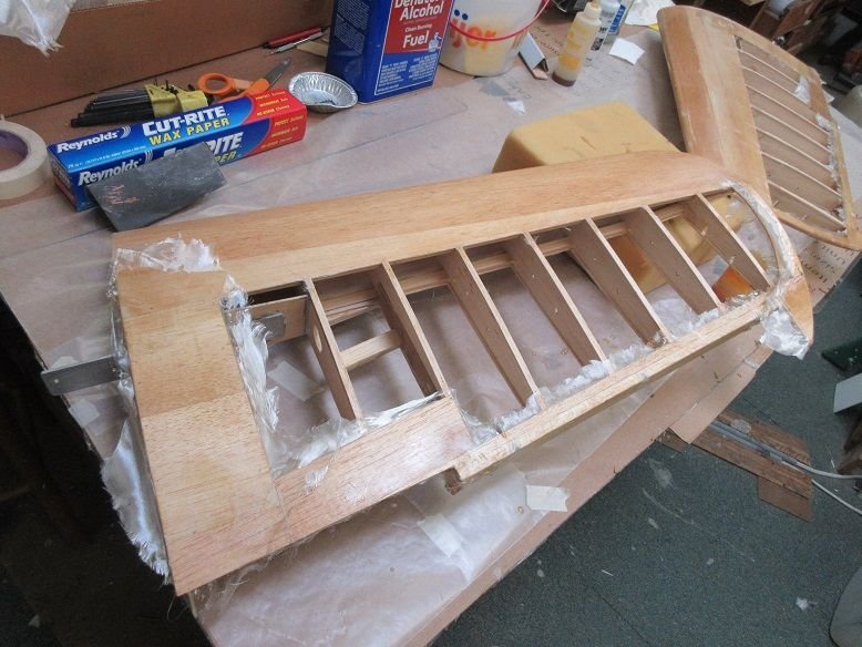
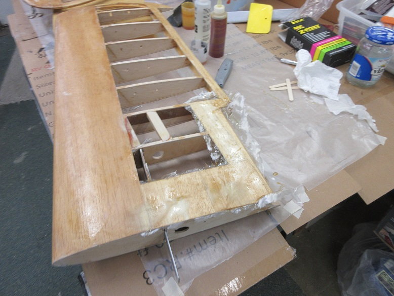
Needed some extra bracing around the flap hinge so cut some aircraft ply for re-enforcement.
Had to cut away some of the wing sheeting to epoxy the new hinge.
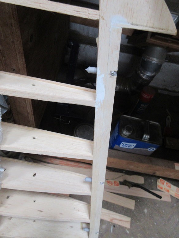
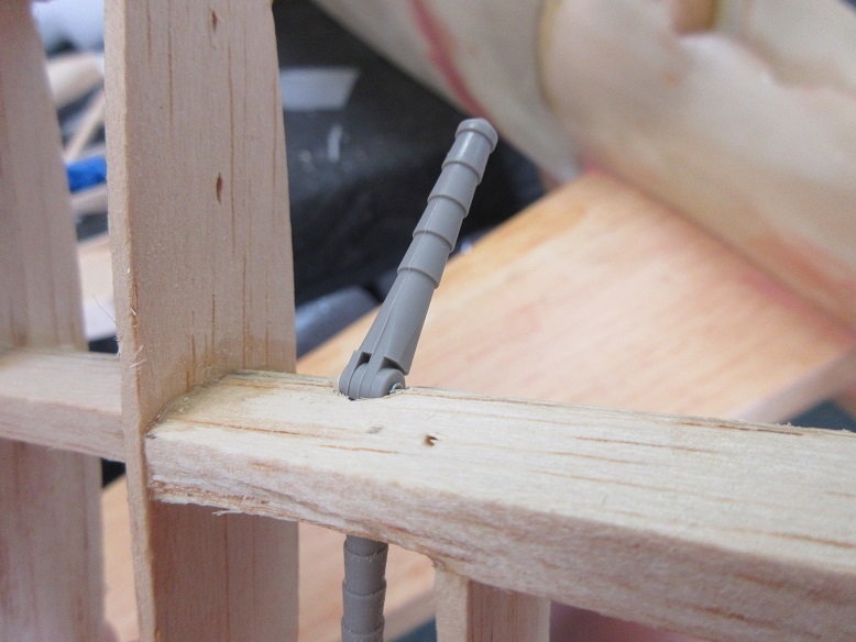
Left outer wing:
Anti-rotation pin was too snug and wing wouldn't mesh so marked the pin with some chalk....

Chalk showed me where to file.
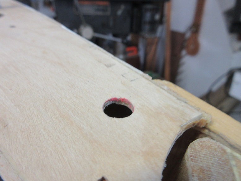
Wing flaps hinges are done. Next will be the ailerons.
Left side:
The inner flap needed a spacer (G-10) to prevent the flap from rubbing the wing.
Inner flap done.
4/40 with locking nuts.
Right side:
I think this control horn is the original builder's idea as, usually, Ziroli's flaps are linked internally and on the LE of the flap. Anyway, since I don't know what internal blockage he did I'll use what he set up.
The ply is a little thin so it is re-enforced with some G-10. I stuck a pin on both sides of the ply to find out where the rib was and cut a slot on the opposite side.
Slop some epoxy on and it should be good 'to go'.
Needed some extra bracing around the flap hinge so cut some aircraft ply for re-enforcement.
Had to cut away some of the wing sheeting to epoxy the new hinge.
Left outer wing:
Anti-rotation pin was too snug and wing wouldn't mesh so marked the pin with some chalk....
Chalk showed me where to file.
Wing flaps hinges are done. Next will be the ailerons.
Last edited by samparfitt; 06-07-2020 at 04:18 PM.
06-08-2020, 04:00 PM
#3
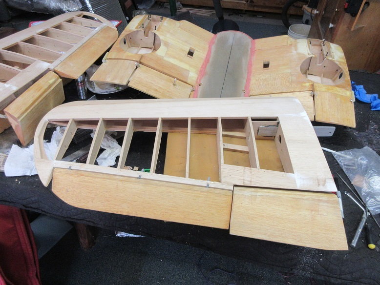
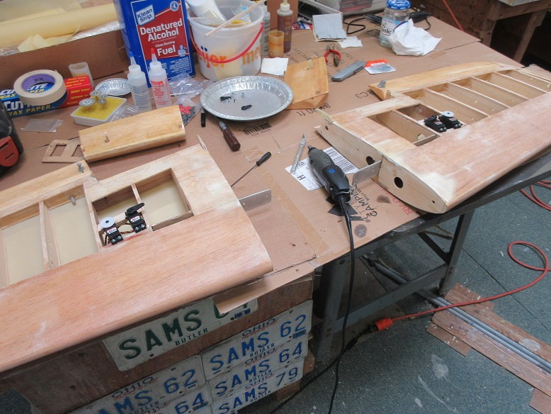
Wings: Aileron hinges installed.
Spent most of the day on daughter's garage but got a few things done on the plane.
Used Robart's large pin hinge and pocket hinge so the ailerons are modular.

Right wing.
Some drilling and force fitting.
All 'dry fitted' for now.

Recessed the pocket hinge to put center of pin hinge between TE of wing and LE of aileron.
Left wing dry fitted.
Spent most of the day on daughter's garage but got a few things done on the plane.
Used Robart's large pin hinge and pocket hinge so the ailerons are modular.
Right wing.
Some drilling and force fitting.
All 'dry fitted' for now.
Recessed the pocket hinge to put center of pin hinge between TE of wing and LE of aileron.
Left wing dry fitted.
06-09-2020, 10:01 AM
#4
Wings: outer (cont)
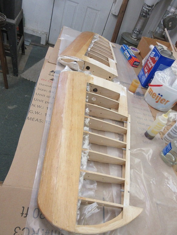
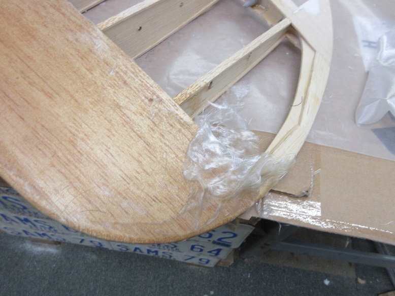
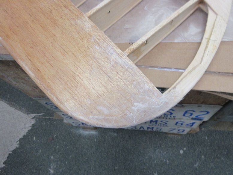
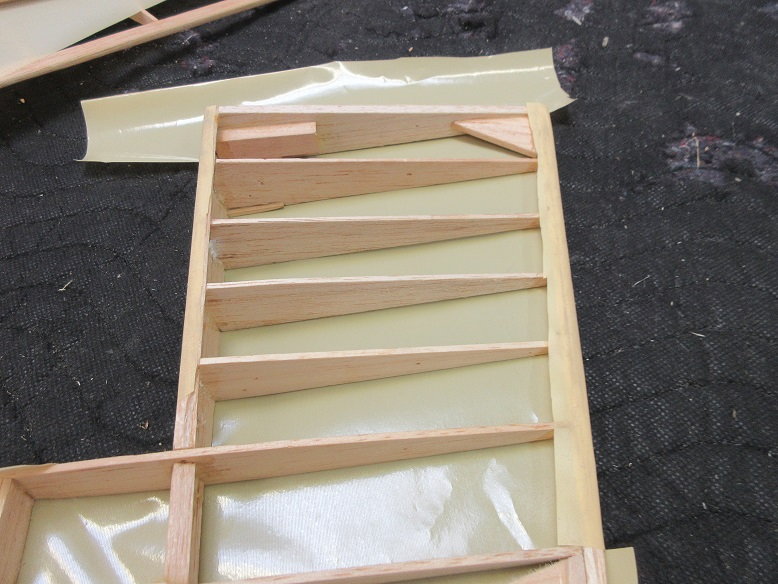
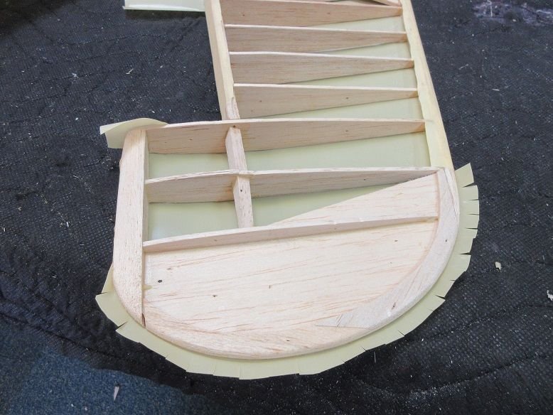
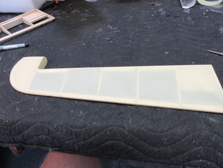
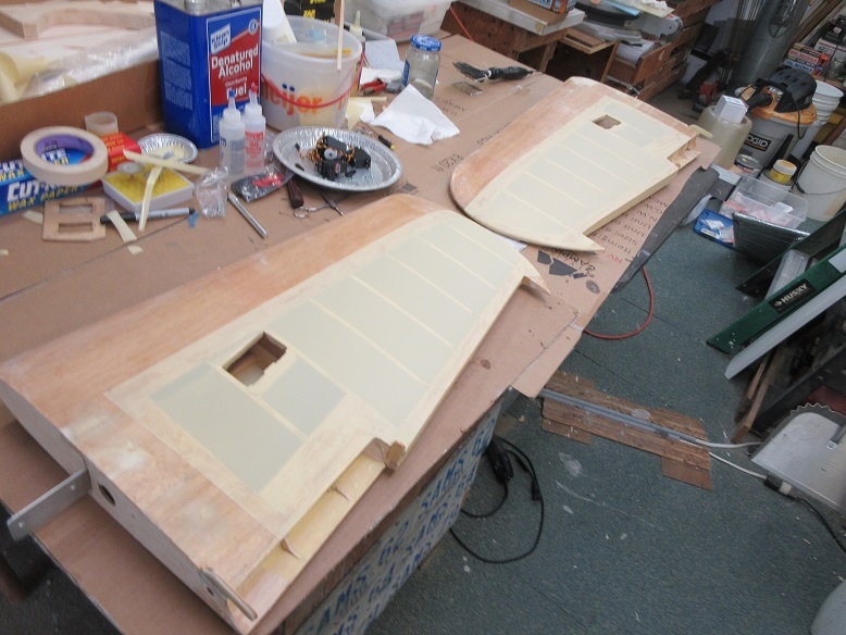
Glassing.
I wasn't going to glass the outer wings but changed my mind. Figure it's good to prevent hanger rash plus let hassles on trying to put solartex over compound curves.
ZAP finishing resin was used and Ziroli's 3/4 oz(if I remember correctly) cloth. Normally I do only one side at a time but, since I'm only doing the LE of the wing, I'll do both sides at once.
The outer edges will not be perfect where both sides of the cloth meet but that is easy to sand.
A bondo applicator (yellow) and paper towels cut into 2" squares are used to smooth the finish.
I'm partial to laying the cloth on the surface and then applying the resin.
Small batches are made as the resin can set up fast. I used about 3 batches per wing. A 'little' goes a long way.
Of course latex gloves are a 'given'.

Yes, they still make wax paper (Krogers). Used the wax paper so the wing didn't stick to the cardboard. Alcohol to clean up, after.
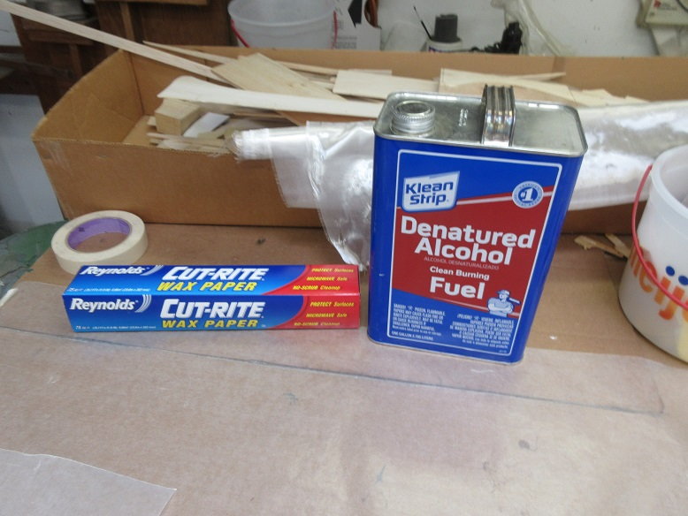
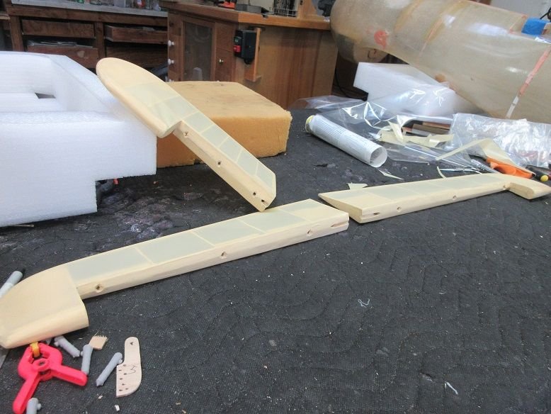
Had to sit them on end so no resin touched any unwanted surfaces. Most of the resin is squeezed out with the bondo applicator and the paper towels to remove any excess that was missed.
Don't want any puddles of the resin as it hardens rock hard and not easy to remove large puddles.
All cloth weave should be dark with no dry spots. You can add more resin, later, if you do miss some dry spots: Just don't sand that area until more resin is applied.
Being 90 out in the detached shop, it shouldn't take too long for this stuff to dry.

I'll glass the TE of the wing, also. Unfortunately, I epoxied the pocket hinges in before making that decision so I'll have to put some oil on the set screw and tape that area off.
Glassing.
I wasn't going to glass the outer wings but changed my mind. Figure it's good to prevent hanger rash plus let hassles on trying to put solartex over compound curves.
ZAP finishing resin was used and Ziroli's 3/4 oz(if I remember correctly) cloth. Normally I do only one side at a time but, since I'm only doing the LE of the wing, I'll do both sides at once.
The outer edges will not be perfect where both sides of the cloth meet but that is easy to sand.
A bondo applicator (yellow) and paper towels cut into 2" squares are used to smooth the finish.
I'm partial to laying the cloth on the surface and then applying the resin.
Small batches are made as the resin can set up fast. I used about 3 batches per wing. A 'little' goes a long way.
Of course latex gloves are a 'given'.
Yes, they still make wax paper (Krogers). Used the wax paper so the wing didn't stick to the cardboard. Alcohol to clean up, after.
Had to sit them on end so no resin touched any unwanted surfaces. Most of the resin is squeezed out with the bondo applicator and the paper towels to remove any excess that was missed.
Don't want any puddles of the resin as it hardens rock hard and not easy to remove large puddles.
All cloth weave should be dark with no dry spots. You can add more resin, later, if you do miss some dry spots: Just don't sand that area until more resin is applied.
Being 90 out in the detached shop, it shouldn't take too long for this stuff to dry.
I'll glass the TE of the wing, also. Unfortunately, I epoxied the pocket hinges in before making that decision so I'll have to put some oil on the set screw and tape that area off.
Last edited by samparfitt; 06-09-2020 at 10:03 AM.
06-09-2020, 12:32 PM
#5
Tail feathers.
The original owner already glassed the stab and left the elevators and rudder bare, which is good since I want to have them cloth covered.
Installing Robart large pin hinges and pocket hinges.
The elevators were drilled out and then a half round hole on the surface to take the center, wide part of the pin hinge so it can rotate.
Minimum of 3 hinges in case one fails.
Center of pin hinge needs to be along back TE of elevator.
Pocket hinges installed in stab.
One hole for the hinge and another towards the bottom of the stab for the reset screw.
Hole drilled in bottom of stab to access set screw.
Dry fit.

Vertical stab.
Ditto for the hinges for the stab and rudder.
Dry fit.
Outer wings (cont).
Only 3.5 hrs and the resin has cured.
Before sanding excess wast cloth.
Some 220 sandpaper easily removes waste.
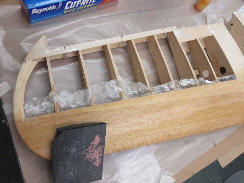
Bottom tip of wing where FG cloth crumpled together. ..
Sanding removed it.
A few minutes work and wings are clean.
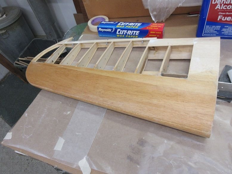
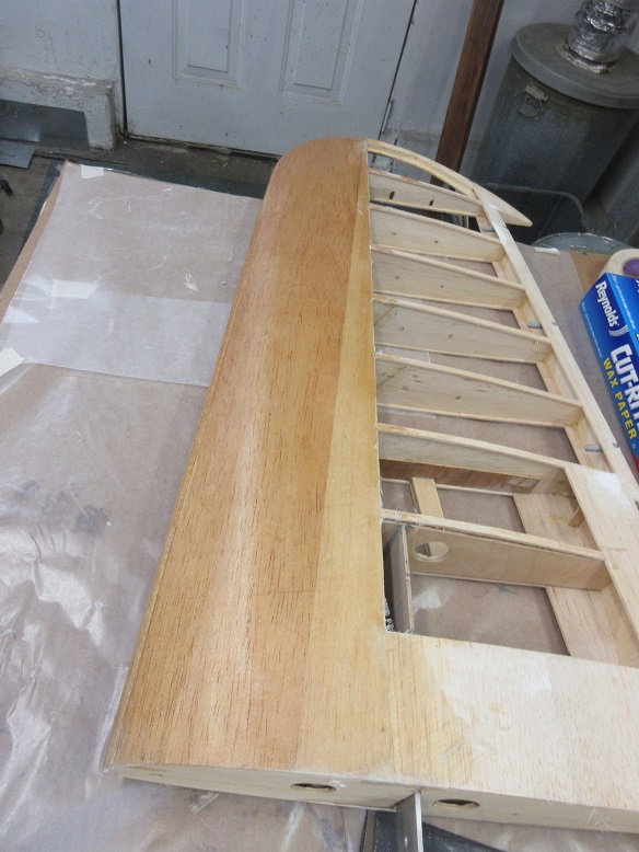
Next, the TE of the outer wings.
The original owner already glassed the stab and left the elevators and rudder bare, which is good since I want to have them cloth covered.
Installing Robart large pin hinges and pocket hinges.
The elevators were drilled out and then a half round hole on the surface to take the center, wide part of the pin hinge so it can rotate.
Minimum of 3 hinges in case one fails.
Center of pin hinge needs to be along back TE of elevator.
Pocket hinges installed in stab.
One hole for the hinge and another towards the bottom of the stab for the reset screw.
Hole drilled in bottom of stab to access set screw.
Dry fit.
Vertical stab.
Ditto for the hinges for the stab and rudder.
Dry fit.
Outer wings (cont).
Only 3.5 hrs and the resin has cured.
Before sanding excess wast cloth.
Some 220 sandpaper easily removes waste.
Bottom tip of wing where FG cloth crumpled together. ..
Sanding removed it.
A few minutes work and wings are clean.
Next, the TE of the outer wings.
06-09-2020, 01:34 PM
#6
Outer wings (cont)
Glassing (cont)
To insure no resin gets into the pocket hinges, I removed the set screw and put some axle grease in the hole...
Plus I masked off the hinges.
Glassed top bottom and back of the TE of the outer wings plus tips and top, inside ends. Only thing left is inside, bottom back ends.

Glassing (cont)
To insure no resin gets into the pocket hinges, I removed the set screw and put some axle grease in the hole...
Plus I masked off the hinges.
Glassed top bottom and back of the TE of the outer wings plus tips and top, inside ends. Only thing left is inside, bottom back ends.
06-09-2020, 04:31 PM
#7
Tail feathers (cont)
Solartex application.
I'm only applying the solartex to one side to make it easier to apply before gluing in the hinges. The other side won't need a complete 'wrap around' around the edges.
Initial cut.

tool of choice.
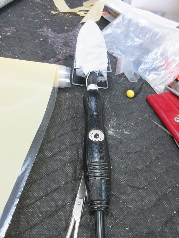
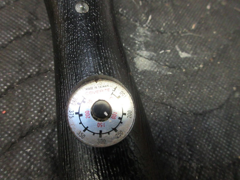
Low heat for solartex: only 100-130 C for gluing edges.
Two long sides done, first.
Big curves need lots of short tabs.
Won't shrink the surface until the other side is done to prevent any warping (non star trek type).
Can, now, glue in the hinges.
Top left elevator.

Tail feathers done.
Cut the general shape for the outer wings but more glassing needs to be done, yet.
After 25 years, I found a new trick. Instead of sanding off the waste cloth, an X-acto blade does it much cleaner without creating any dust!
Applied the final cloth to inner, bottom edges of outer wings. Let that 'cook' overnight.
Solartex application.
I'm only applying the solartex to one side to make it easier to apply before gluing in the hinges. The other side won't need a complete 'wrap around' around the edges.
Initial cut.
tool of choice.
Low heat for solartex: only 100-130 C for gluing edges.
Two long sides done, first.
Big curves need lots of short tabs.
Won't shrink the surface until the other side is done to prevent any warping (non star trek type).
Can, now, glue in the hinges.
Top left elevator.
Tail feathers done.
Cut the general shape for the outer wings but more glassing needs to be done, yet.
After 25 years, I found a new trick. Instead of sanding off the waste cloth, an X-acto blade does it much cleaner without creating any dust!
Applied the final cloth to inner, bottom edges of outer wings. Let that 'cook' overnight.
06-10-2020, 06:22 AM
#8
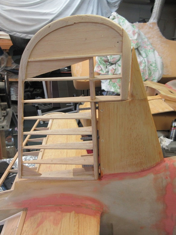
Outer Wings (cont)
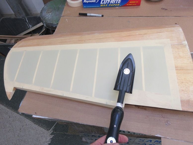
Sanding and Solartex application.
Sanded all surfaces using 100 grit: may appear too low of grit but needed to remove excess resin.

All surfaces should be dull after sanding.
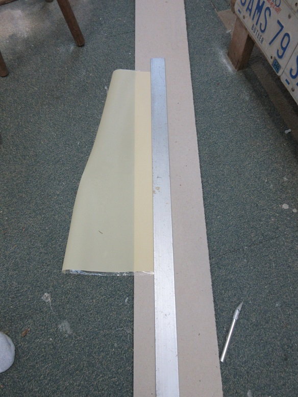
Solartex application.
Used a metal ruler to get a nice straight line.
Took the 'sock' off to get better conductivity. Can't do that with some painted coverings as the color comes off.
After edges done at 130 C, did the center at 150 C.
Only did the top, so far. May need to access inside.
Wiped all surfaces with alcohol before applying solartex.
Moving surfaces (cont).
Epoxied the pin hinges into elevators, rudder and ailerons.

Sanding and Solartex application.
Sanded all surfaces using 100 grit: may appear too low of grit but needed to remove excess resin.
All surfaces should be dull after sanding.
Solartex application.
Used a metal ruler to get a nice straight line.
Took the 'sock' off to get better conductivity. Can't do that with some painted coverings as the color comes off.
After edges done at 130 C, did the center at 150 C.
Only did the top, so far. May need to access inside.
Wiped all surfaces with alcohol before applying solartex.
Moving surfaces (cont).
Epoxied the pin hinges into elevators, rudder and ailerons.
06-10-2020, 01:28 PM
#9
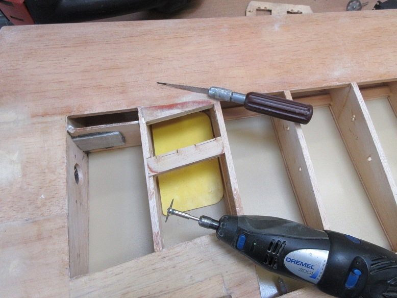
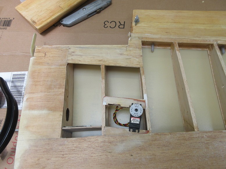
Stuff:
Epoxied pocket hinges into horizontal and vertical stab.
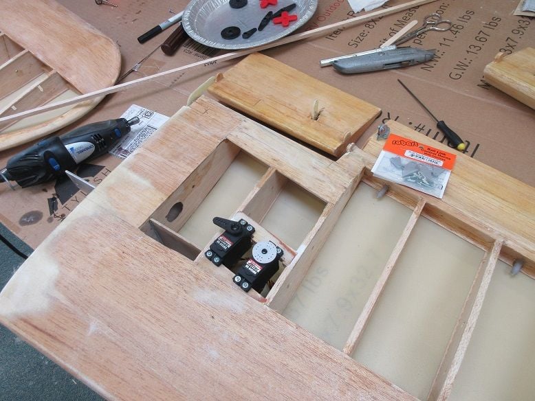
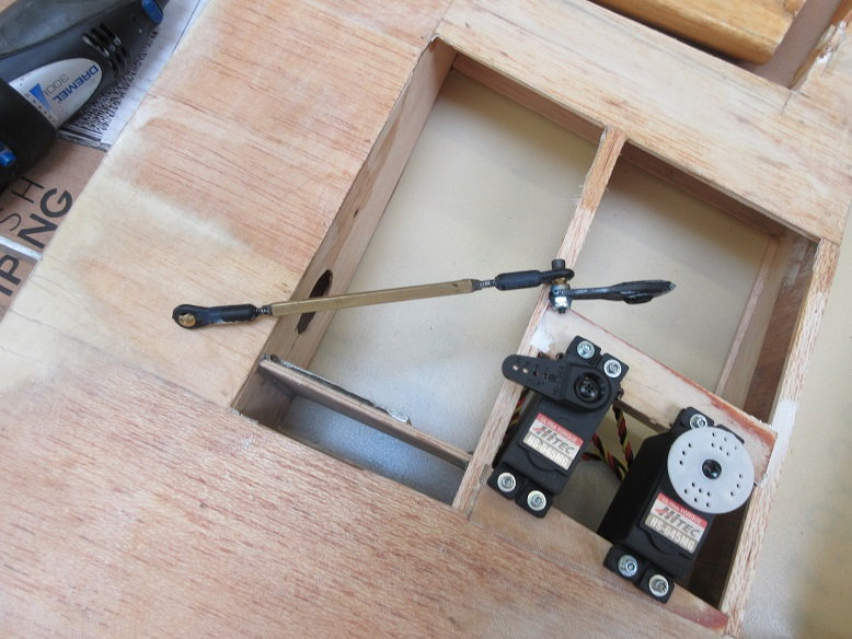
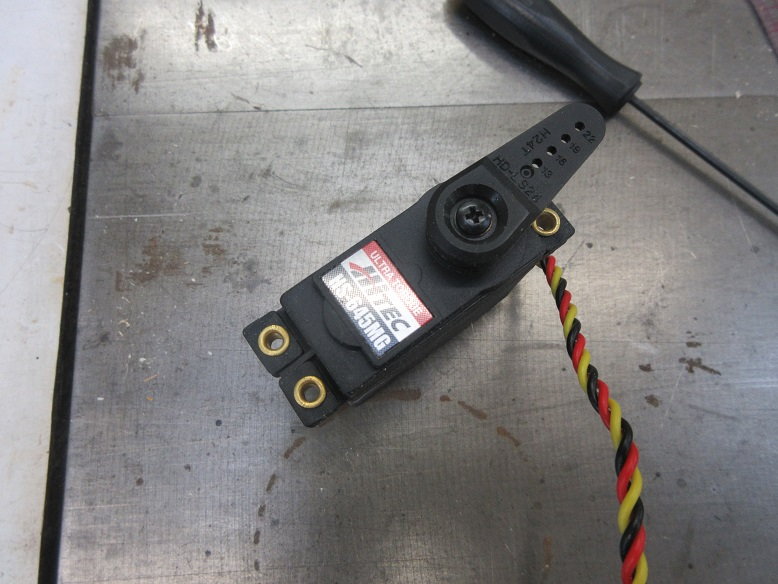
Outer wings: bottom servo tray for flaps and ailerons. Had to cut notches in the mounts to accept the HS-645's. Put a barrier on the top solartex so I don't, accidentally, puncture it.
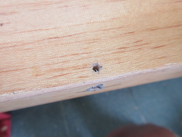
Robart ball link control horns on the ailerons.
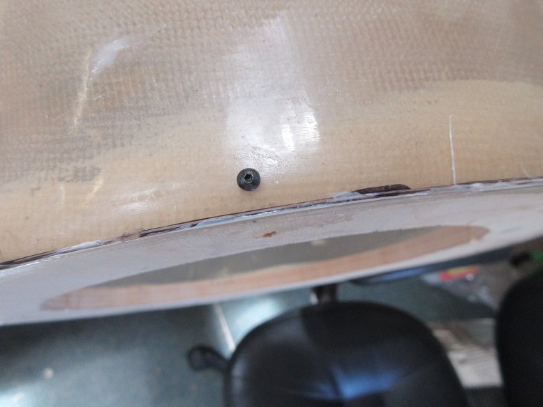
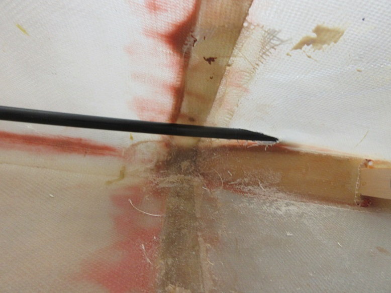
Fortunately, the original builder put ply under the sheeting on the ailerons to mount control horns. A pin stuck in the sheeting verified the ply was there, per the plans.
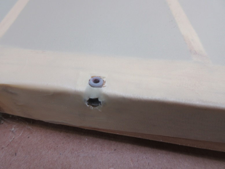
Covering cut away around the pocket hinges.
The servo arm will also get ball links: dubro 4/40's.
Original owner of plane made elevators to accept a U shaped steel rod controlled by one servo.
I'll be using two servos and two control horns. I had to build up the ply layer to the surface to install robarts ball link control horns.
Outer wing servos installed and removed before applying solartex to bottom of wings.
Fabric cut for servo tray holes.
Solartex applied to bottom of tail feathers.
Original builder has an L shaped steel rod to control the rudder that goes internally into the fuse. Not sure if I'll go with an external control horn or mount an arm to the steel rod.
This is the U control horn for the elevator: I'm not comfortable having a set screw arm moving both elevators. I can live if the rudder arm fails but not the elevators.
Epoxied pocket hinges into horizontal and vertical stab.
Outer wings: bottom servo tray for flaps and ailerons. Had to cut notches in the mounts to accept the HS-645's. Put a barrier on the top solartex so I don't, accidentally, puncture it.
Robart ball link control horns on the ailerons.
Fortunately, the original builder put ply under the sheeting on the ailerons to mount control horns. A pin stuck in the sheeting verified the ply was there, per the plans.
Covering cut away around the pocket hinges.
The servo arm will also get ball links: dubro 4/40's.
Original owner of plane made elevators to accept a U shaped steel rod controlled by one servo.
I'll be using two servos and two control horns. I had to build up the ply layer to the surface to install robarts ball link control horns.
Outer wing servos installed and removed before applying solartex to bottom of wings.
Fabric cut for servo tray holes.
Solartex applied to bottom of tail feathers.
Original builder has an L shaped steel rod to control the rudder that goes internally into the fuse. Not sure if I'll go with an external control horn or mount an arm to the steel rod.
This is the U control horn for the elevator: I'm not comfortable having a set screw arm moving both elevators. I can live if the rudder arm fails but not the elevators.
Last edited by samparfitt; 06-10-2020 at 01:30 PM.
06-10-2020, 06:42 PM
#10
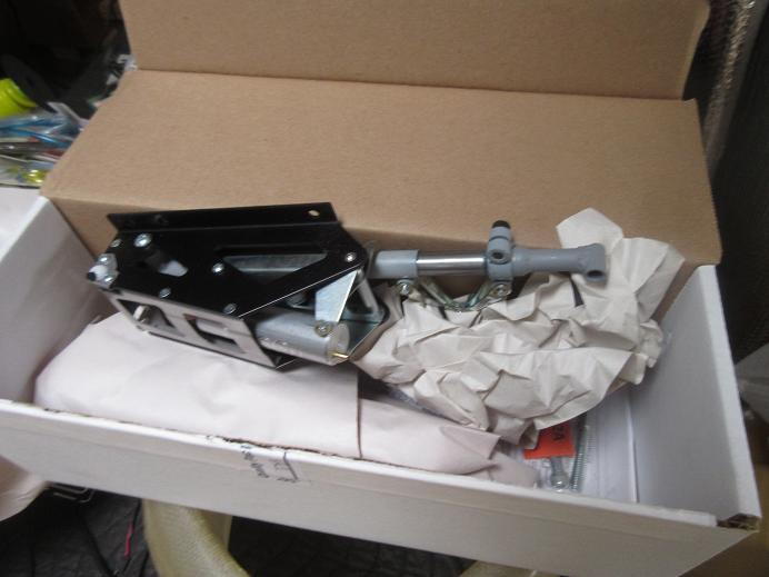
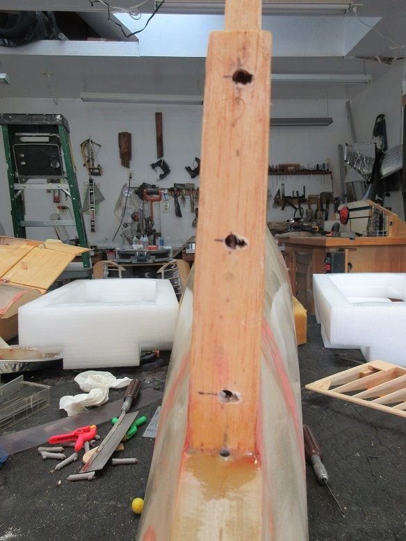
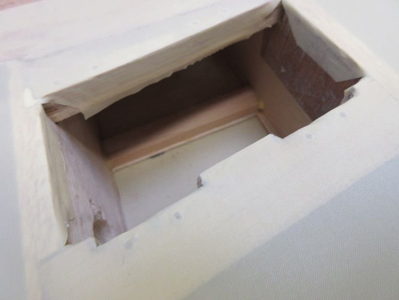
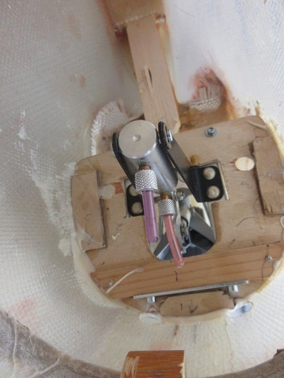
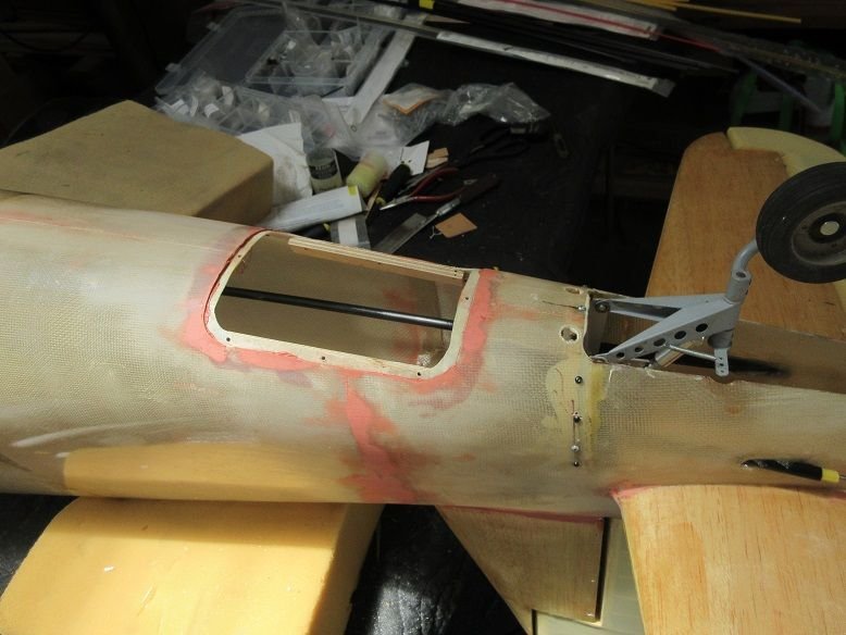
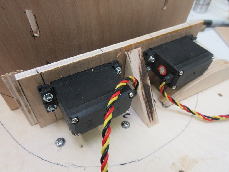
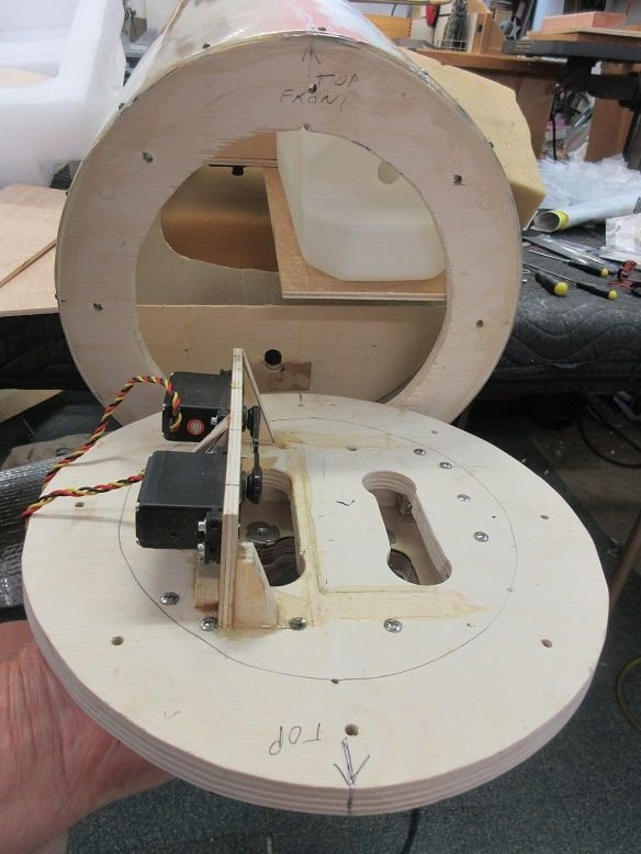
Tail retract:
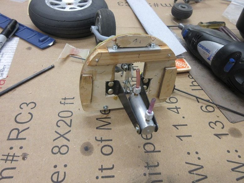
Was trying to insert the retract into the fuse former and it fell out. Glad that happen as needed to make some updates.
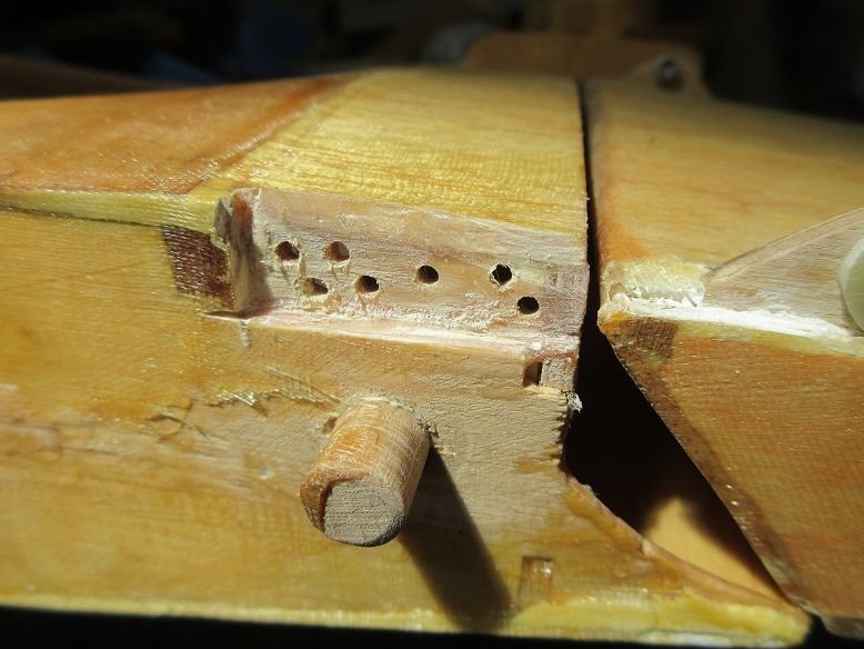
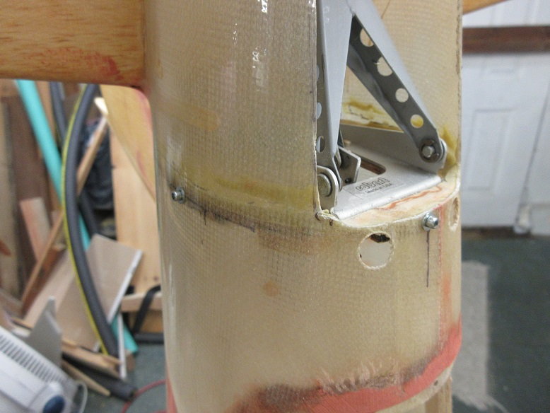
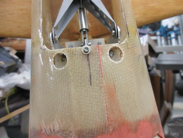
The retract wasn't sitting flush to the former so some wood was removed where the black extensions are located in the picture.
Also, added three extra pieces of ply to the former so some button head screws can be used for a mechanical fastener as well as hysol to secure the former to the FG fuse.
Also, had to enlarge the slot where the top of the retract is secured to the former.
In addition, servo screws used to secure the two gear mounting blocks to the former.
The former is aircraft ply so that didn't need replacing.
These measures should be good enough to insure the former doesn't break or come loose.
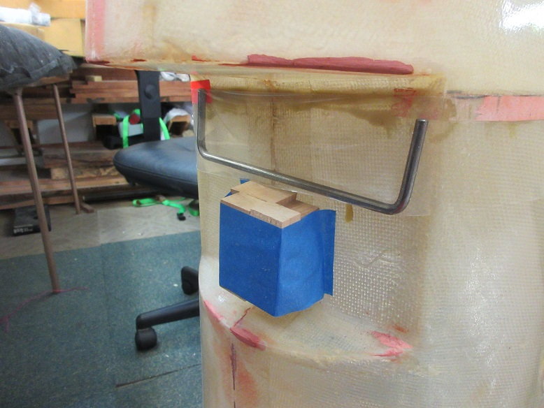
Thought I'd check to see if the rudder can be moved internally: nada.
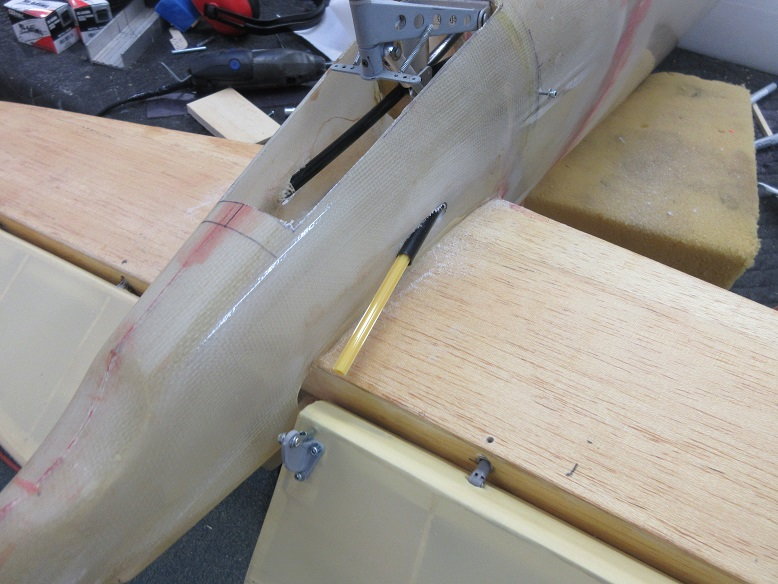
I had a large control arm that I attached to the L shaped steel rod.....
but it interferes with the tail retract in the UP position. The original 1992 plans use the internal method but Nick also used a fixed tail gear.
The low weights given on the plans are always amusing: no doors, fixed tail, one servo to control inner flaps, no cockpit detail; just a bare, minimum plane. Probably not glassed, either.
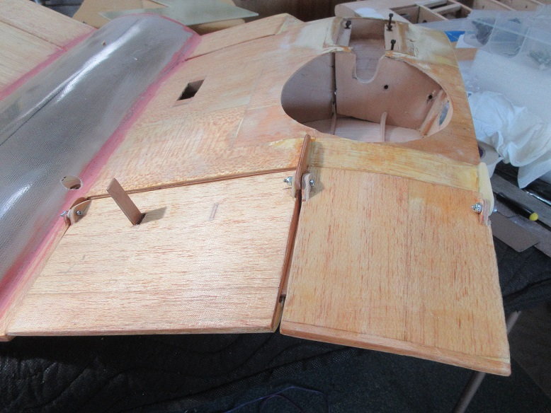
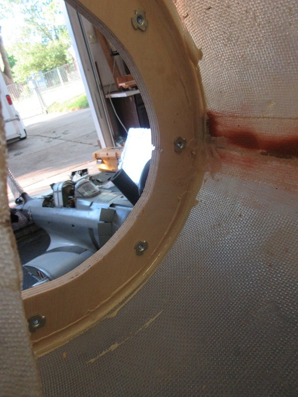
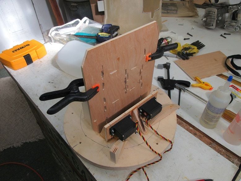
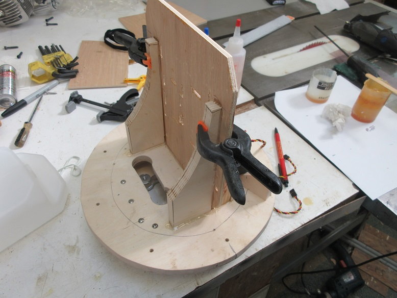
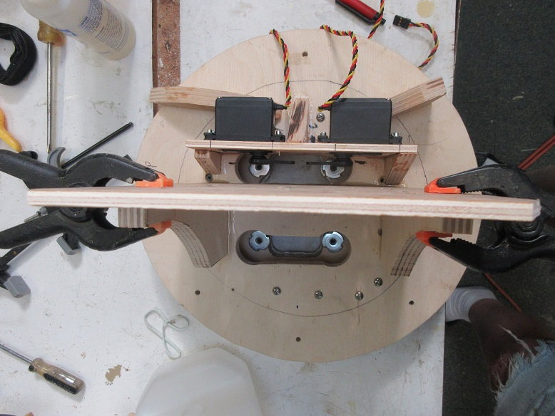
Gear former temporarily secured to fuse. Will use button head screws to look like rivets.
Don't know if original builder put these holes in but needed to secure gear to former.
Door opening had to be enlarged.
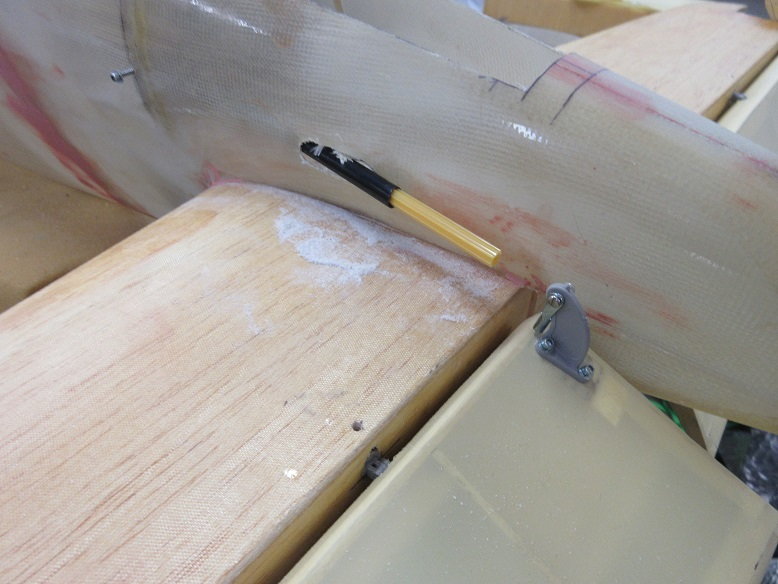
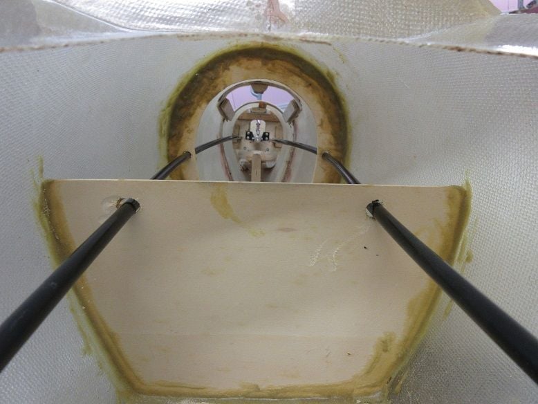
The black spot on the vertical stab is about where I'll need a hole to control the rudder. Probably will use Sullivan golden rods.
Ditto for elevator rods.

Keeping everything modular, the engine mount cone on the FG fuse will be cut off and two fire walls will be mounted (one fixed and one removable) which will have tank and throttle/choke servos.
Was trying to insert the retract into the fuse former and it fell out. Glad that happen as needed to make some updates.
The retract wasn't sitting flush to the former so some wood was removed where the black extensions are located in the picture.
Also, added three extra pieces of ply to the former so some button head screws can be used for a mechanical fastener as well as hysol to secure the former to the FG fuse.
Also, had to enlarge the slot where the top of the retract is secured to the former.
In addition, servo screws used to secure the two gear mounting blocks to the former.
The former is aircraft ply so that didn't need replacing.
These measures should be good enough to insure the former doesn't break or come loose.
Thought I'd check to see if the rudder can be moved internally: nada.
I had a large control arm that I attached to the L shaped steel rod.....
but it interferes with the tail retract in the UP position. The original 1992 plans use the internal method but Nick also used a fixed tail gear.
The low weights given on the plans are always amusing: no doors, fixed tail, one servo to control inner flaps, no cockpit detail; just a bare, minimum plane. Probably not glassed, either.
Gear former temporarily secured to fuse. Will use button head screws to look like rivets.
Don't know if original builder put these holes in but needed to secure gear to former.
Door opening had to be enlarged.
The black spot on the vertical stab is about where I'll need a hole to control the rudder. Probably will use Sullivan golden rods.
Ditto for elevator rods.
Keeping everything modular, the engine mount cone on the FG fuse will be cut off and two fire walls will be mounted (one fixed and one removable) which will have tank and throttle/choke servos.
Last edited by samparfitt; 06-10-2020 at 06:50 PM.
06-11-2020, 10:03 AM
#11
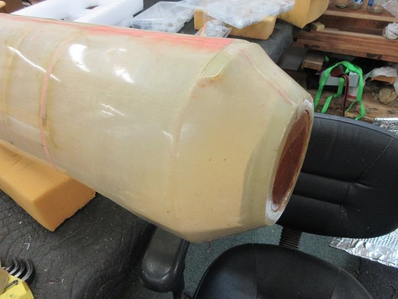
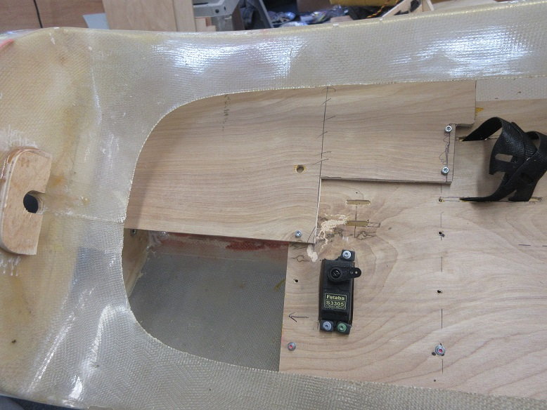
Engine compartment.
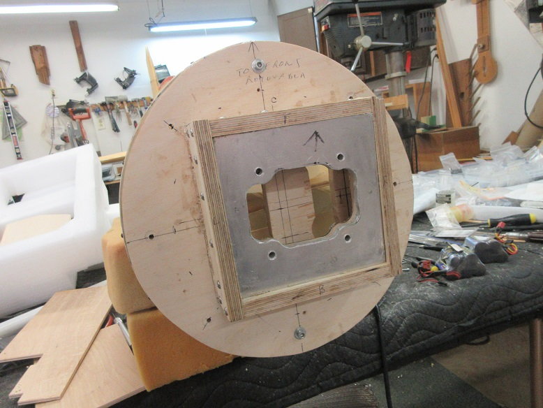
Installing a removable firewall:
Marked off the area to be cut to remove the front FG motor mount section. A diamond impregnated metal cut off wheel made 'quick work' of it.
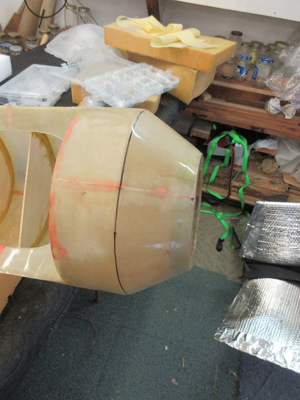
Made a cardboard template.
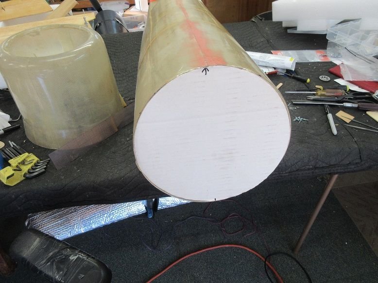
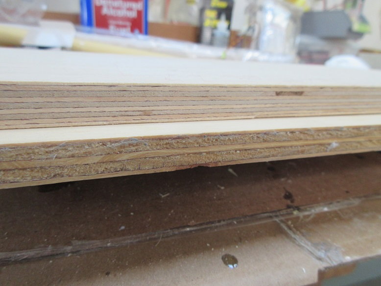
Got some 1/2" thick, 9 ply baltic birch plywood at Rockler wood working shop. Screwed two pieces together.
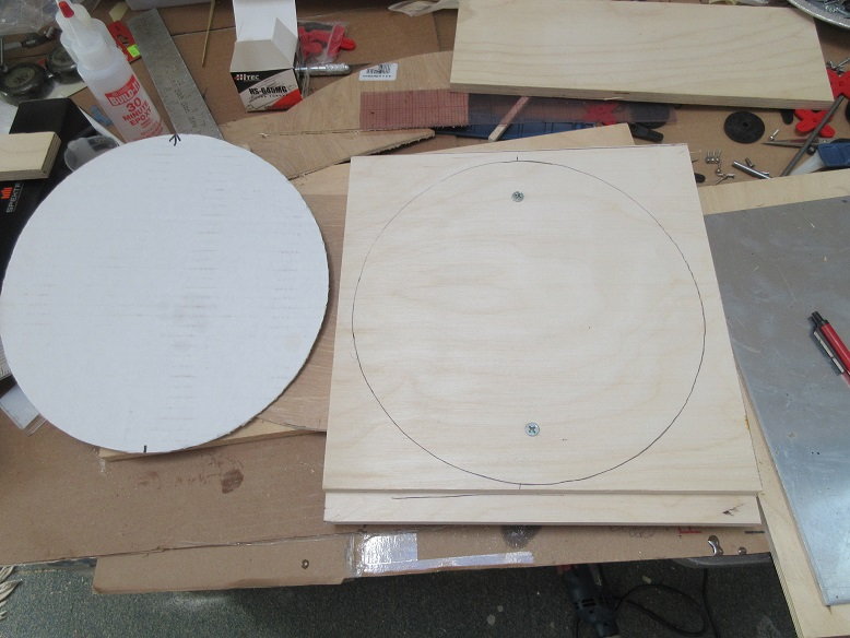
Big difference between the baltic ply and the stuff at HD. 9 ply versus 5 ply.
Cut the ply on the band saw.
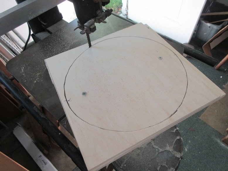
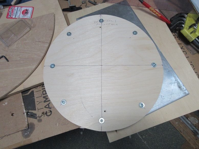
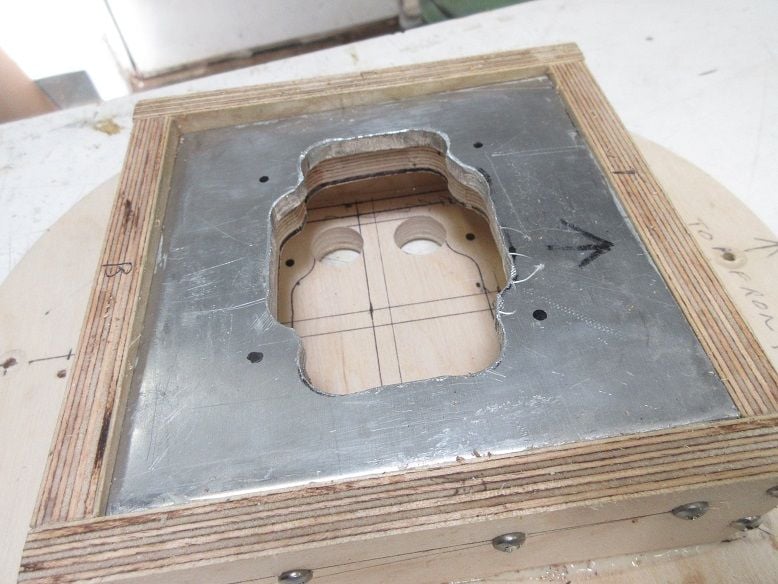
The ply firewall that is attached to the fuse. The inner hole is 1.5" from the outside. A jigsaw used to cut the hole. Drilled and put 4 hex head servo screws at 3, 6, 9 and 12 o clock. Pre-screws needed before adding Hysol.
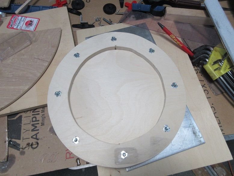
Used #8 bolts and blind nuts to secure the outer removable fire wall from the inner fire wall.
Front:
back.
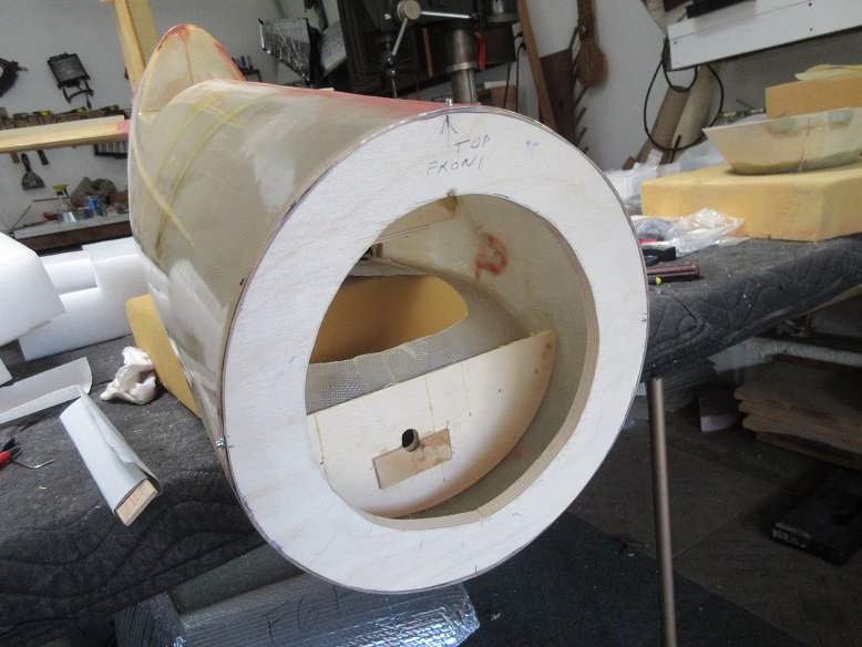
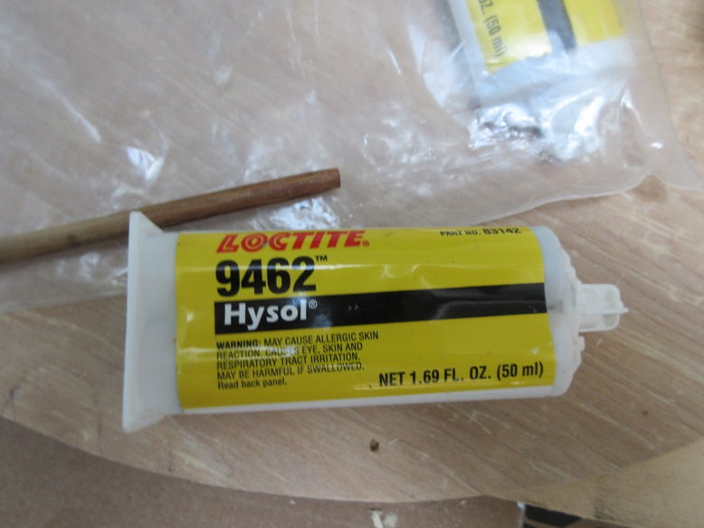
Need a strong glue for engine area.
Hysol applied to edge of fire wall and FG fuse. Roughed up the inside of the fuse plus cleaned with enamel reducer.
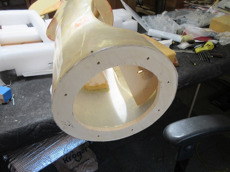
Put 4 button head screws to align the fire wall to the fuse. After the Hysol 'cooks' for several hours, many more button head screws will be added.
The button heads will resemble rivets.
Besides glue, mechanical fasteners always used for anything around the engine compartment.
Installing a removable firewall:
Marked off the area to be cut to remove the front FG motor mount section. A diamond impregnated metal cut off wheel made 'quick work' of it.
Made a cardboard template.
Got some 1/2" thick, 9 ply baltic birch plywood at Rockler wood working shop. Screwed two pieces together.
Big difference between the baltic ply and the stuff at HD. 9 ply versus 5 ply.
Cut the ply on the band saw.
The ply firewall that is attached to the fuse. The inner hole is 1.5" from the outside. A jigsaw used to cut the hole. Drilled and put 4 hex head servo screws at 3, 6, 9 and 12 o clock. Pre-screws needed before adding Hysol.
Used #8 bolts and blind nuts to secure the outer removable fire wall from the inner fire wall.
Front:
back.
Need a strong glue for engine area.
Hysol applied to edge of fire wall and FG fuse. Roughed up the inside of the fuse plus cleaned with enamel reducer.
Put 4 button head screws to align the fire wall to the fuse. After the Hysol 'cooks' for several hours, many more button head screws will be added.
The button heads will resemble rivets.
Besides glue, mechanical fasteners always used for anything around the engine compartment.
Last edited by samparfitt; 06-11-2020 at 10:11 AM.
06-11-2020, 04:35 PM
#12
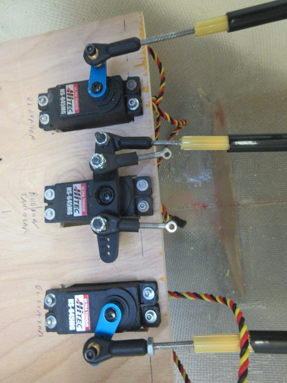
Stuff:
Servo tray.
Epoxies some ply to two fuse formers to secure the tray via screws.
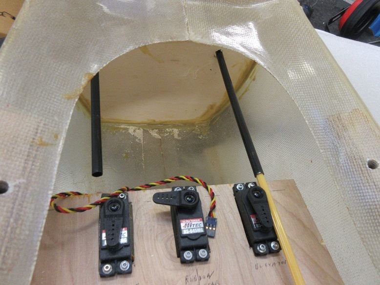
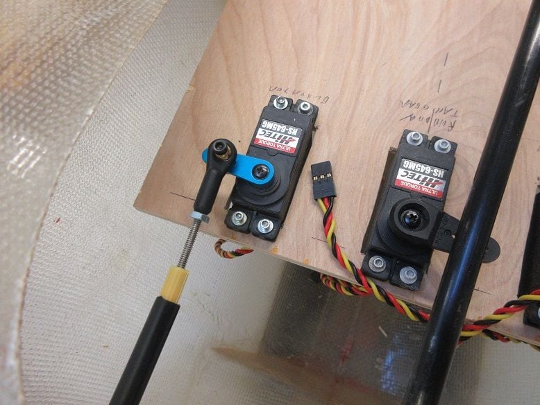
Servo tray: 8"X10". Servos for elevators, rudder and gear valve. Straps for receiver.

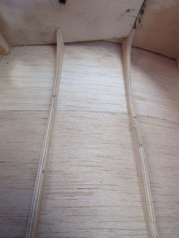
Elevator push rods.
This is new territory for me as I like short linkages so the servos are always next to the moving surface. Being pre-built by someone else, I'm going the Sullivan golden rod route.
Some slots cut for exterior part of push rod leading to elevator control horn.
Both elevator push rods dry fitted.
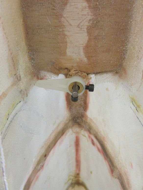
The tail wheel retract former got two holes to route the pushrods.

Some holes were drilled in the fuse formers to guide the push rods. I'm hoping this is enough and don't get any bending when force is applied.
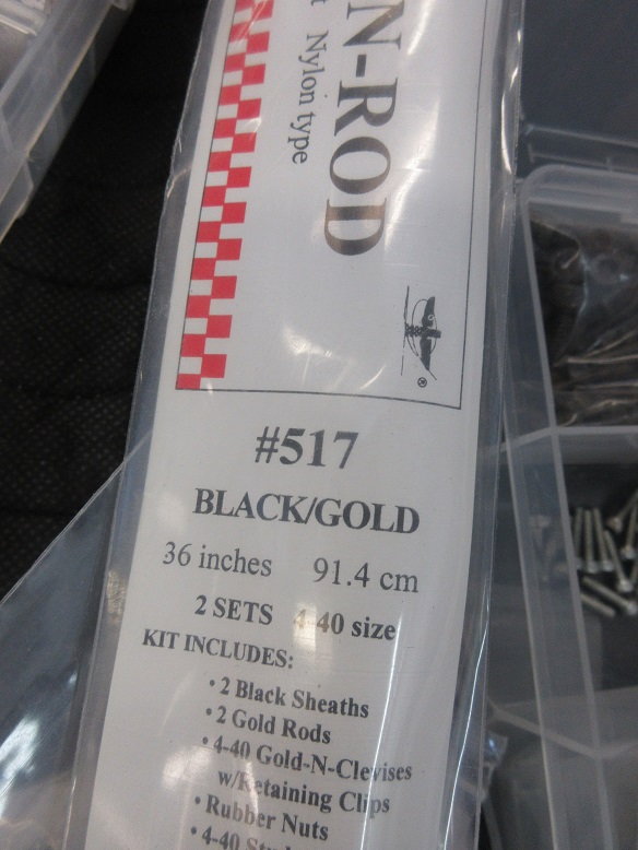
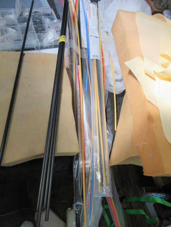
The push rods that I'm using. I think these are the largest they make!
Fire wall: more Hysol added.
Finally, the tail wheel retract former was Hysol'ed in place with 3 button head screws for mechanically securing the former.
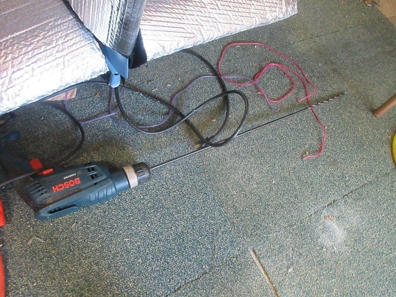
A 30" drill bit used to make holes in the fuse formers.
Rudder push rod.
Servo tray.
Epoxies some ply to two fuse formers to secure the tray via screws.
Servo tray: 8"X10". Servos for elevators, rudder and gear valve. Straps for receiver.
Elevator push rods.
This is new territory for me as I like short linkages so the servos are always next to the moving surface. Being pre-built by someone else, I'm going the Sullivan golden rod route.
Some slots cut for exterior part of push rod leading to elevator control horn.
Both elevator push rods dry fitted.
The tail wheel retract former got two holes to route the pushrods.
Some holes were drilled in the fuse formers to guide the push rods. I'm hoping this is enough and don't get any bending when force is applied.
The push rods that I'm using. I think these are the largest they make!
Fire wall: more Hysol added.
Finally, the tail wheel retract former was Hysol'ed in place with 3 button head screws for mechanically securing the former.
A 30" drill bit used to make holes in the fuse formers.
Rudder push rod.
Last edited by samparfitt; 06-11-2020 at 04:40 PM.
06-12-2020, 07:58 AM
#13
In addition to the Hysol, the fire wall secured with button head screws every 2 inches.
Ditto for the tail gear former.
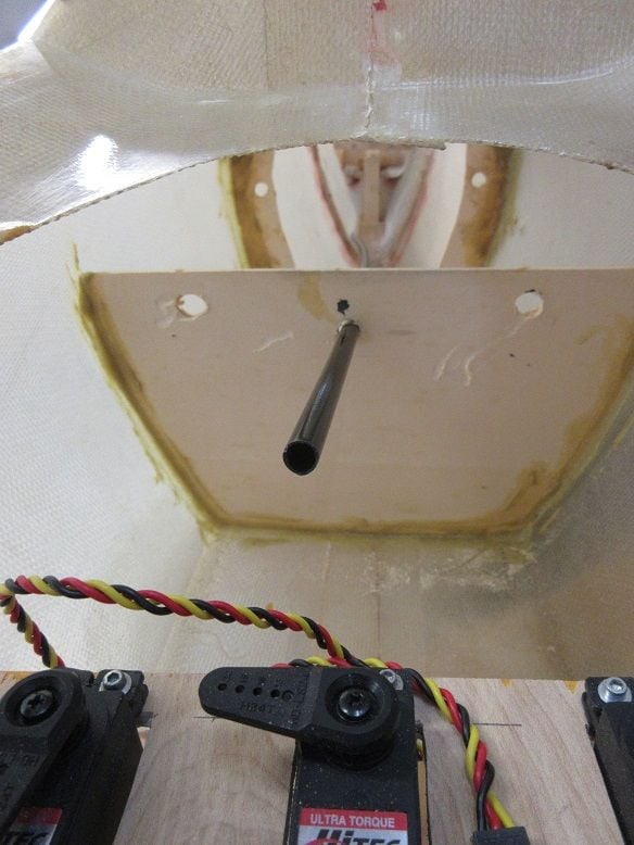
Elevators.
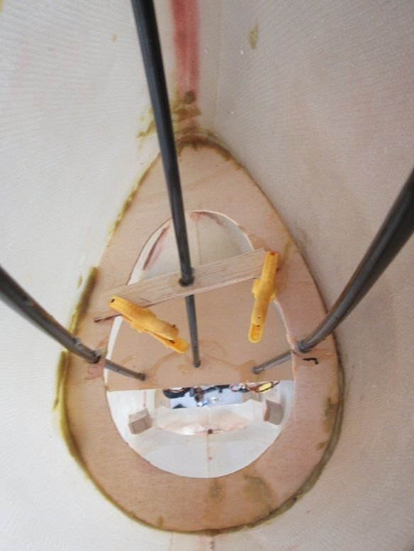
Epoxied the black guide tube to the formers. After the epoxy dried, tested to insure no flexing so this works well. I'm guessing support for the tubing is needed about every foot to insure no flexing.
Ball links at both ends.
I had some carbon fiber rods but, not being a 'straight line' run, the golden rod was a better choice.
Rudder.
Ditto for the black tubing.

Extra support needed for the rudder golden rod.
NOTES:
Noticed a space is best added between pictures as, sometimes, they are confused as one: My other web site automatically puts a space between pictures.
Sometimes I still get 'unable to load pictures' so I need to log out and back in.

Ditto for the tail gear former.
Elevators.
Epoxied the black guide tube to the formers. After the epoxy dried, tested to insure no flexing so this works well. I'm guessing support for the tubing is needed about every foot to insure no flexing.
Ball links at both ends.
I had some carbon fiber rods but, not being a 'straight line' run, the golden rod was a better choice.
Rudder.
Ditto for the black tubing.
Extra support needed for the rudder golden rod.
NOTES:
Noticed a space is best added between pictures as, sometimes, they are confused as one: My other web site automatically puts a space between pictures.
Sometimes I still get 'unable to load pictures' so I need to log out and back in.
Last edited by samparfitt; 06-12-2020 at 08:03 AM.
06-12-2020, 04:49 PM
#14
More stuff:
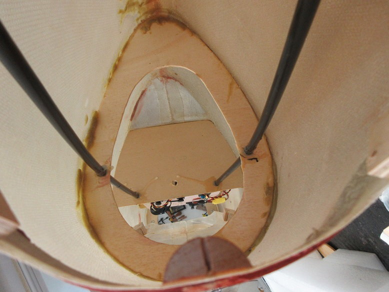
I'm guessing the original builder made this access hole. Glad he did as tail installation is a lot easier with it.
Rudder (center servo).
Used an extra wide servo arm for rudder and tail wheel. Rudder ball link on the outside to get max movement and tail wheel ball links close to center to reduce excess movement.
Ball link to rudder.
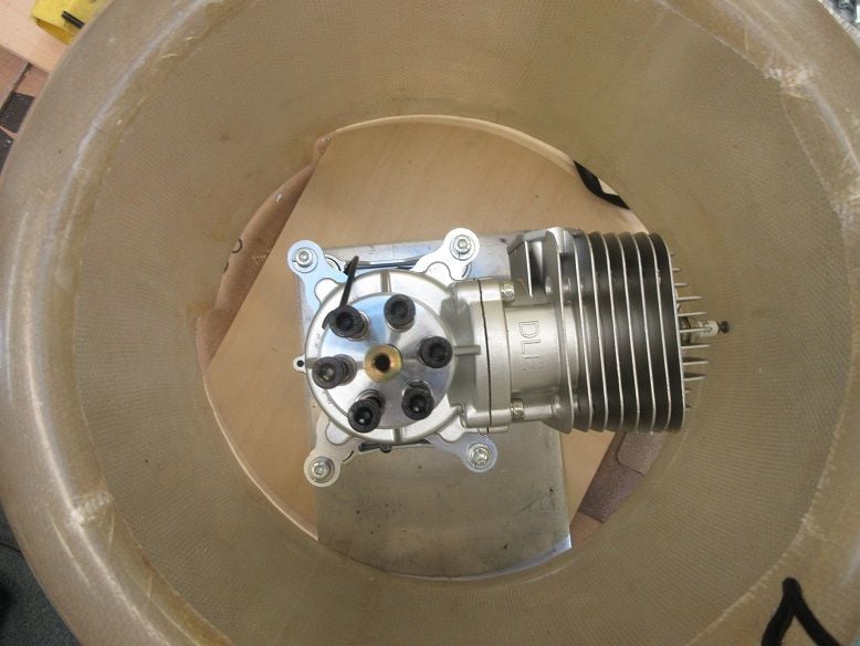
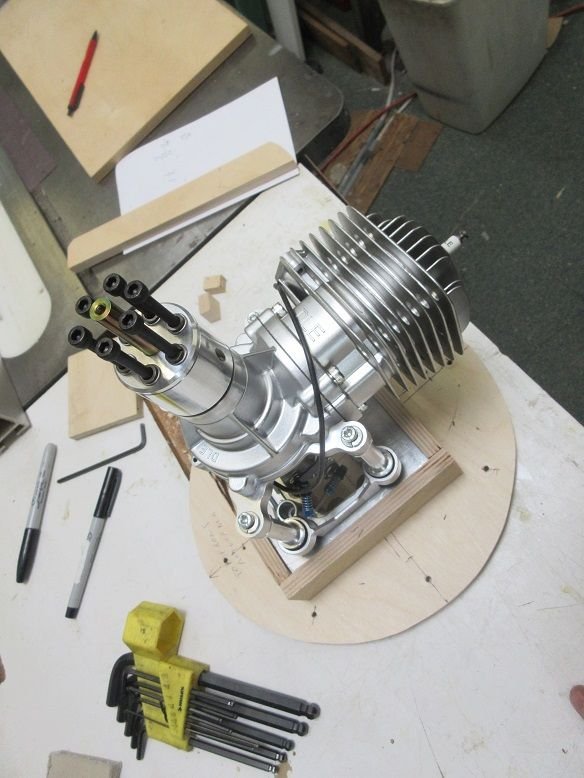
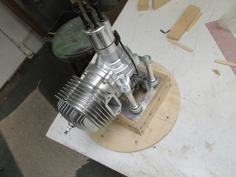
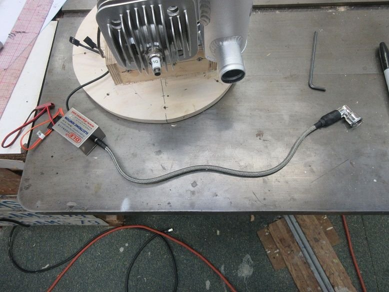
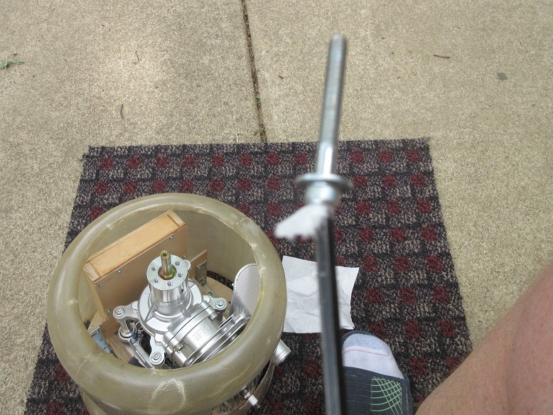
Engine.
Using a DLE-85. Impressed by including a muffler and all the nice hardware to install the engine.

Very nice anti-vibration mount for the engine. I'm guessing they include this to keep people from putting stress on the engine mounts by not installing it in a perfect plane (geometry wise, not airplane wise).
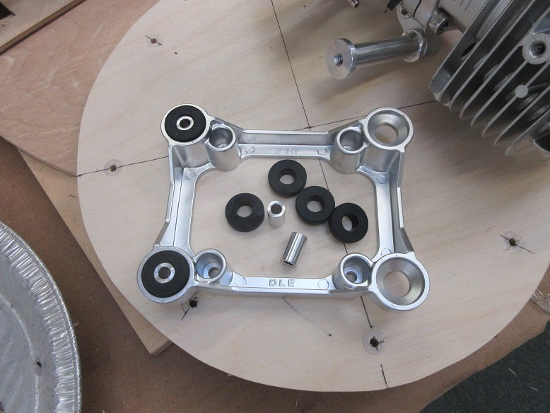
Only extra hardware I added was locking washers.
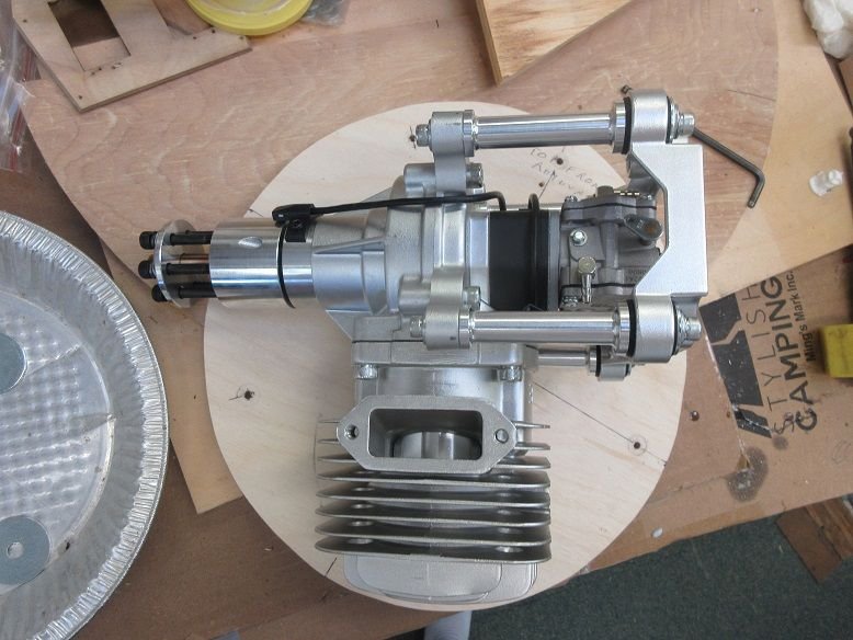

Sullivan easy connect ball links added to throttle and choke arms.
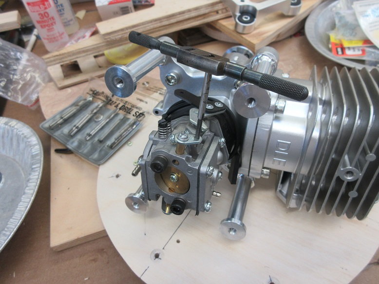
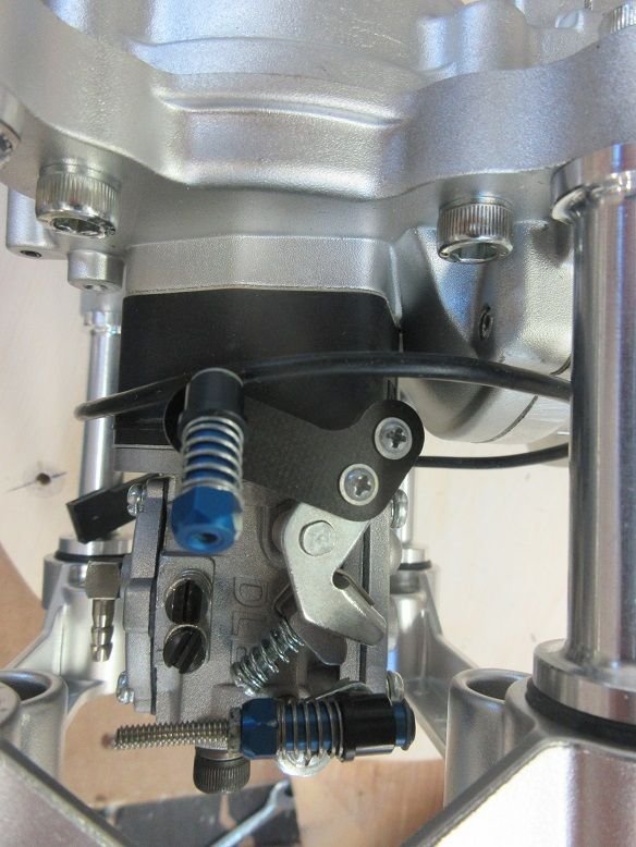
The choke arm needed tapping for the 4/40 threaded ball. I'm partial to servo operated chokes: Easy to open and close and, should the throttle servo 'lock' in high, no need to wait to run out of fuel, just slowly close the choke via the slide lever that I connect it to, to make a normal landing. Also nice, should the gear not come down, I can easily cut the engine before belly landing and, usually, save the prop.
The choke has a lever on the other side at a different angle for those who want to manually control the choke.
Like these connections by Sullivan. Easy to remove for PM.
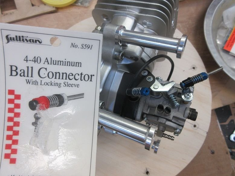
The throttle lever is user friendly: direct line back to where you want your servo.
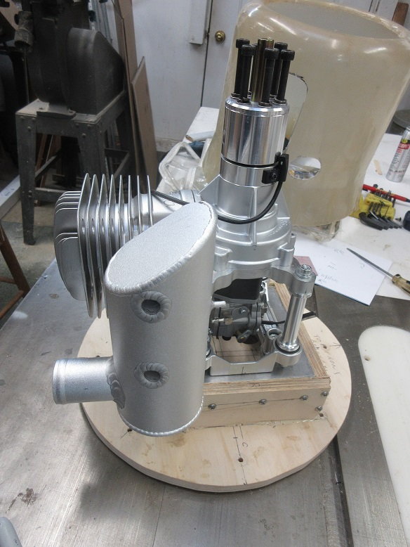
Removable fire wall and engine marriage. Probably, will use a metal plate for mounting.

Engine is larger than the cowl so hole will be cut in bottom of cowl. Need good air circulation, anyway.
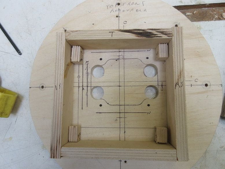
Plans show offset down and to the right. I usually just add an 1/8" to the left and top of the engine mount.
That moves the nose of the engine over a 1/4" inch so the mount will have to be offset the same amount.
Original (O) mount location and shifted 1/4" over. Two circles for throttle/choke linkage and third hole for fuel line.
Dotted line indicates where fuse fire wall is so must stay inside that line for clearance for mounting anything from the back side of the removable fire wall.
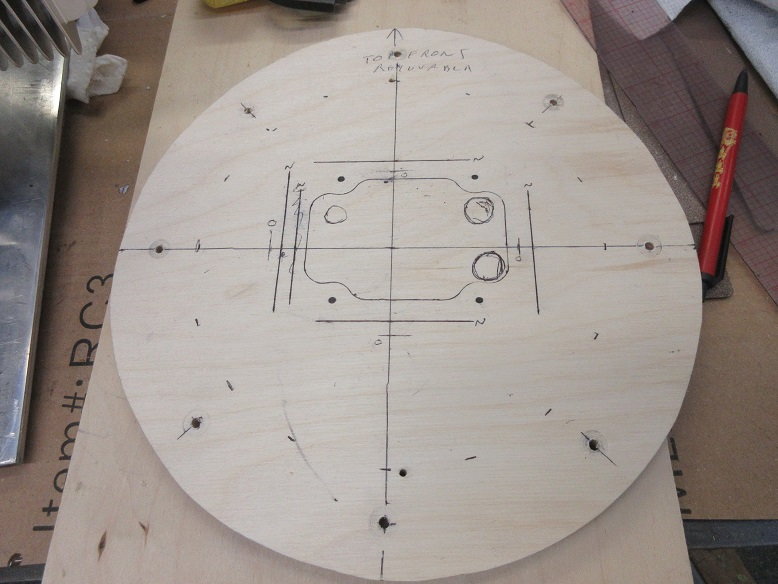
Holes needed for linkages.
Back of removable fire wall so, again, framing for tank and servos do not exceed fuse fire wall.
I'm guessing the original builder made this access hole. Glad he did as tail installation is a lot easier with it.
Rudder (center servo).
Used an extra wide servo arm for rudder and tail wheel. Rudder ball link on the outside to get max movement and tail wheel ball links close to center to reduce excess movement.
Ball link to rudder.
Engine.
Using a DLE-85. Impressed by including a muffler and all the nice hardware to install the engine.
Very nice anti-vibration mount for the engine. I'm guessing they include this to keep people from putting stress on the engine mounts by not installing it in a perfect plane (geometry wise, not airplane wise).
Only extra hardware I added was locking washers.
Sullivan easy connect ball links added to throttle and choke arms.
The choke arm needed tapping for the 4/40 threaded ball. I'm partial to servo operated chokes: Easy to open and close and, should the throttle servo 'lock' in high, no need to wait to run out of fuel, just slowly close the choke via the slide lever that I connect it to, to make a normal landing. Also nice, should the gear not come down, I can easily cut the engine before belly landing and, usually, save the prop.
The choke has a lever on the other side at a different angle for those who want to manually control the choke.
Like these connections by Sullivan. Easy to remove for PM.
The throttle lever is user friendly: direct line back to where you want your servo.
Removable fire wall and engine marriage. Probably, will use a metal plate for mounting.
Engine is larger than the cowl so hole will be cut in bottom of cowl. Need good air circulation, anyway.
Plans show offset down and to the right. I usually just add an 1/8" to the left and top of the engine mount.
That moves the nose of the engine over a 1/4" inch so the mount will have to be offset the same amount.
Original (O) mount location and shifted 1/4" over. Two circles for throttle/choke linkage and third hole for fuel line.
Dotted line indicates where fuse fire wall is so must stay inside that line for clearance for mounting anything from the back side of the removable fire wall.
Holes needed for linkages.
Back of removable fire wall so, again, framing for tank and servos do not exceed fuse fire wall.
Last edited by samparfitt; 06-12-2020 at 05:12 PM.
06-13-2020, 10:35 AM
#15
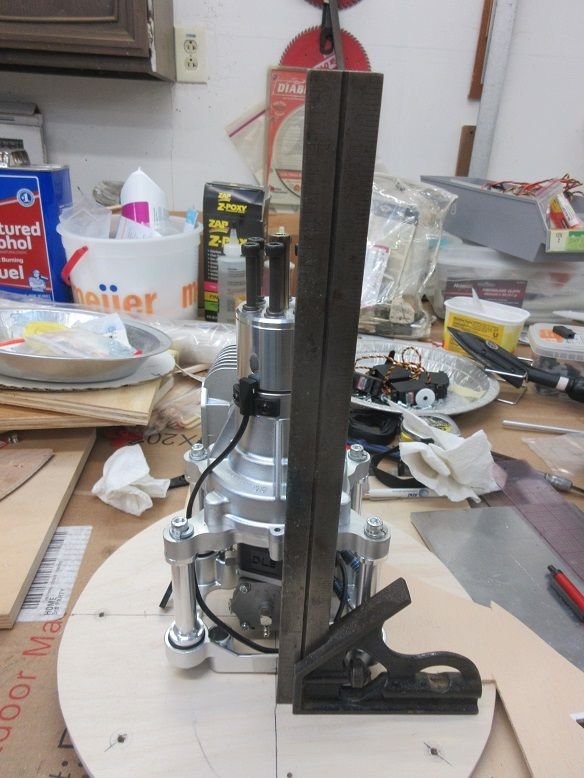
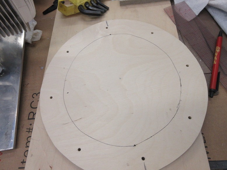
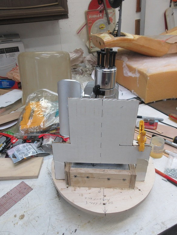
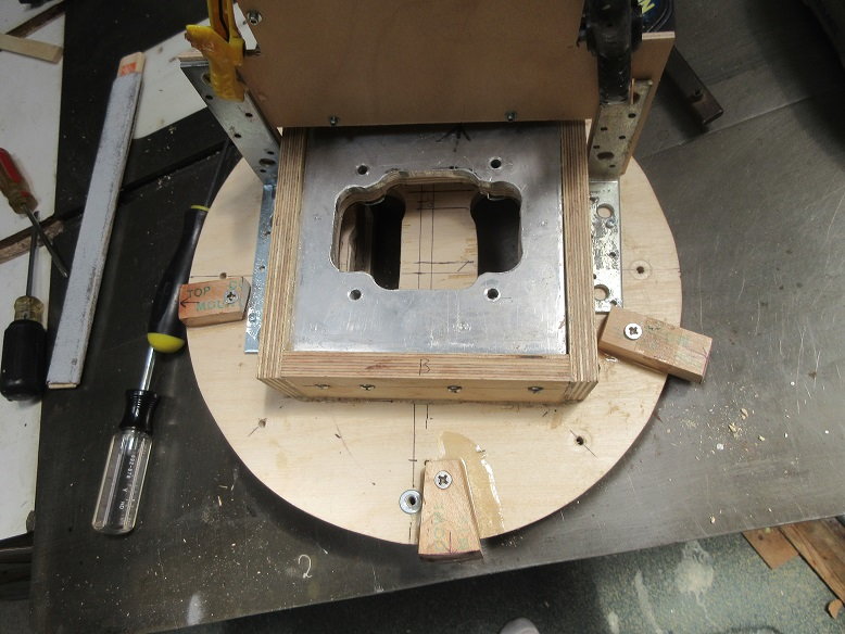
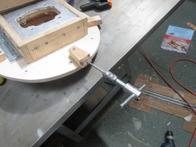
Engine mount.
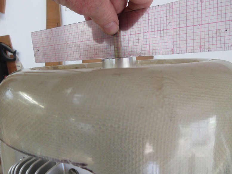
Engine mount needs to be 1 3/4" high for prop to clear front of cowl.
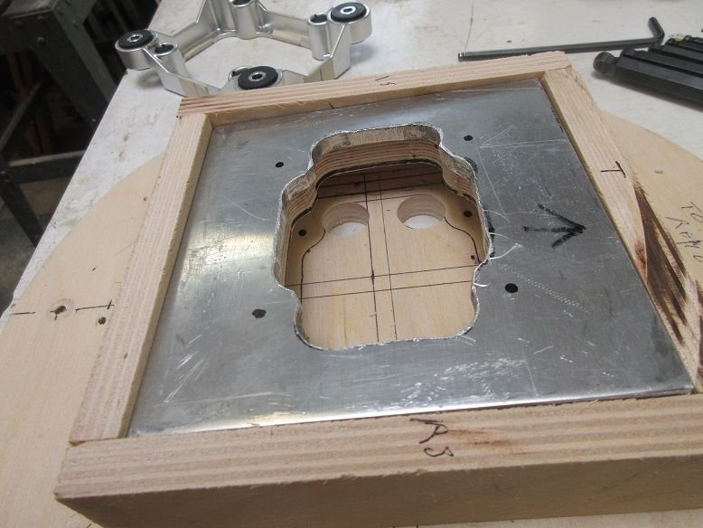
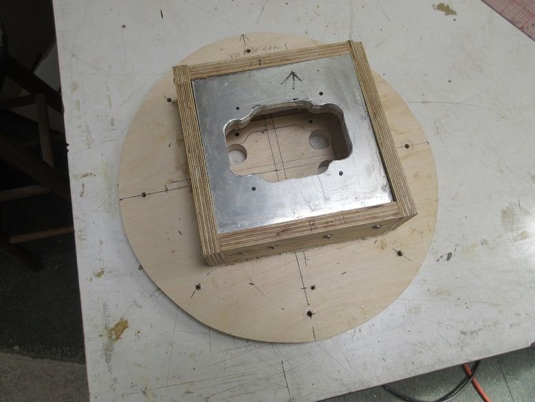
3/4" Forstner bit used to make access for throttle/choke linkage and fuel line on removable fire wall.

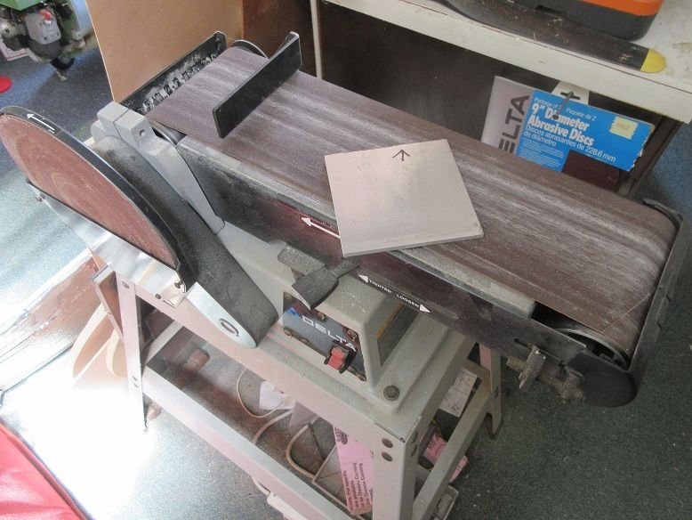
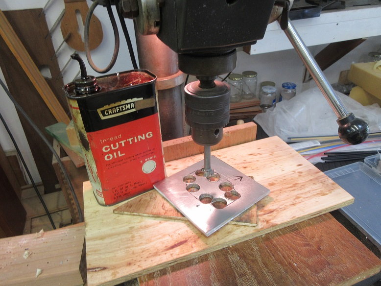
Engine mount faces cut: aluminum and 1/2" thick baltic burch ply.
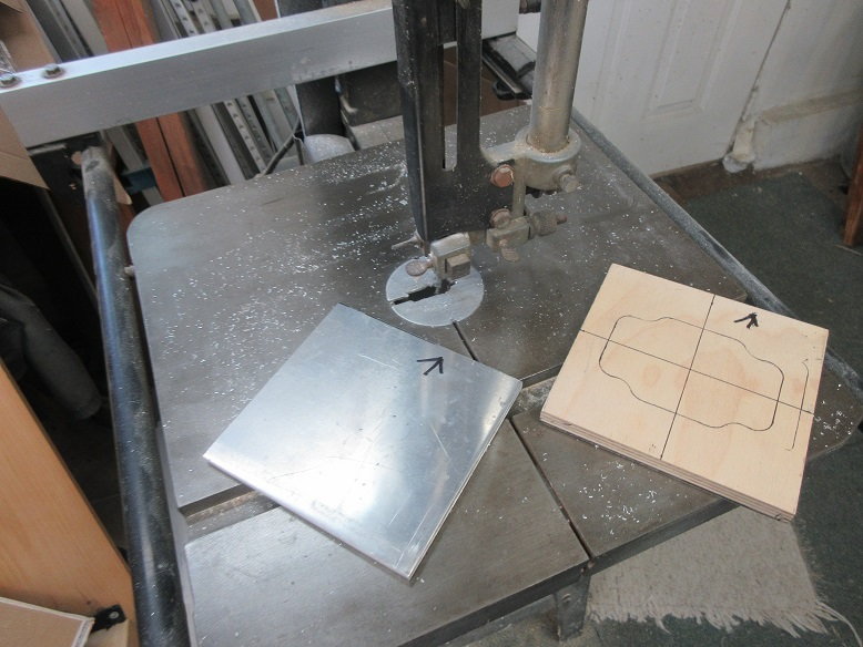
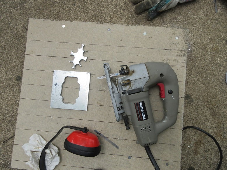
Aggressive grit needed to smooth edges on aluminum piece.
Total thickness is 11/16"
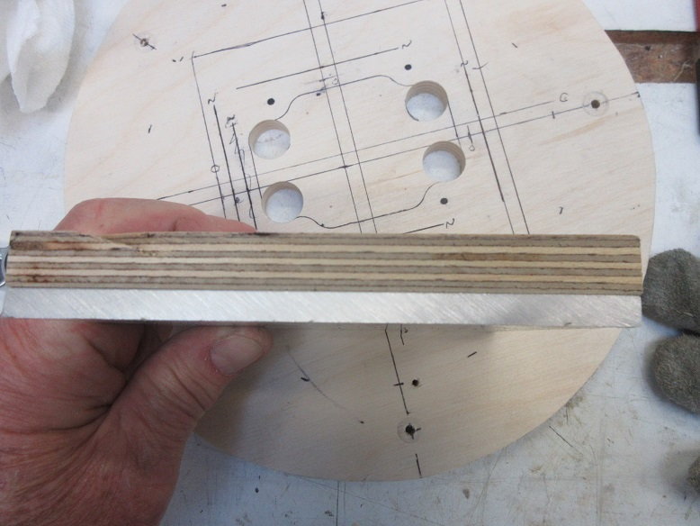
Forstner bit used to cut the rounded edges and scroll saw to finish the cut.
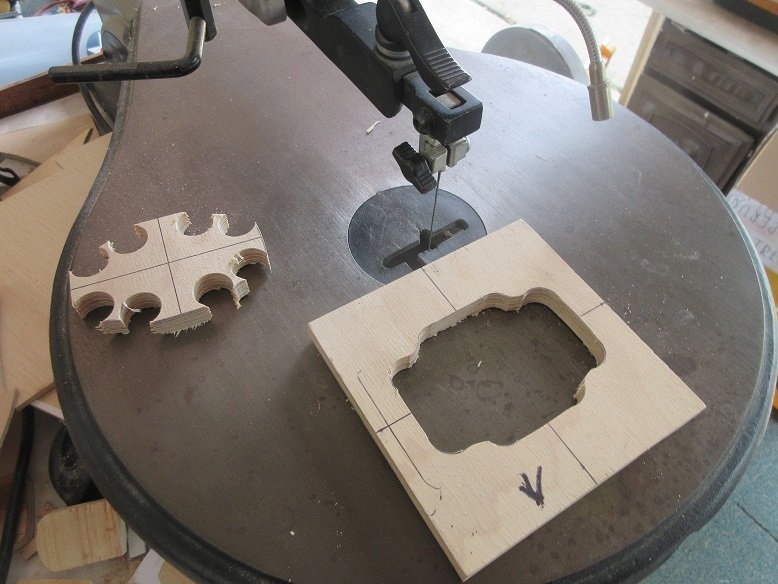
Carbide forstner bit needed on the aluminum.
Jig saw finished up the final cuts.
Sides of engine mount cut. 1/2" thick X 1 3/4" high baltic ply.
Some risers made; top right highest, left top and right bottom an 1/8" lower and the lower left a 1/4" lower than the top right riser.
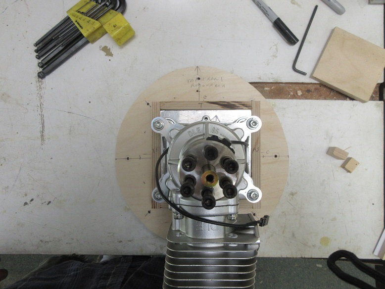
Dry fit face pieces to insure down and left offset of engine.
'eyeball' that engine shaft is centered.
Cowl 1/4" lower than back of prop location.
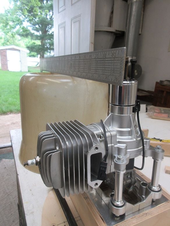
Engine mount needs to be 1 3/4" high for prop to clear front of cowl.
3/4" Forstner bit used to make access for throttle/choke linkage and fuel line on removable fire wall.
Engine mount faces cut: aluminum and 1/2" thick baltic burch ply.
Aggressive grit needed to smooth edges on aluminum piece.
Total thickness is 11/16"
Forstner bit used to cut the rounded edges and scroll saw to finish the cut.
Carbide forstner bit needed on the aluminum.
Jig saw finished up the final cuts.
Sides of engine mount cut. 1/2" thick X 1 3/4" high baltic ply.
Some risers made; top right highest, left top and right bottom an 1/8" lower and the lower left a 1/4" lower than the top right riser.
Dry fit face pieces to insure down and left offset of engine.
'eyeball' that engine shaft is centered.
Cowl 1/4" lower than back of prop location.
 06-13-2020, 12:19 PM
#17
Thanks, Brian,
After 60 something years of building things, i should have picked up a few 'good' habits' and probably have forgotten a few!
==============
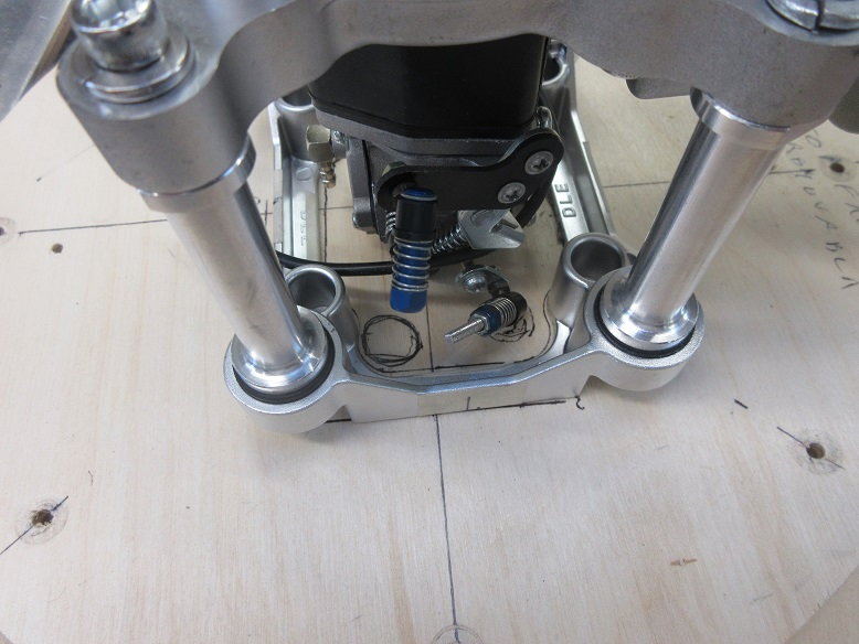
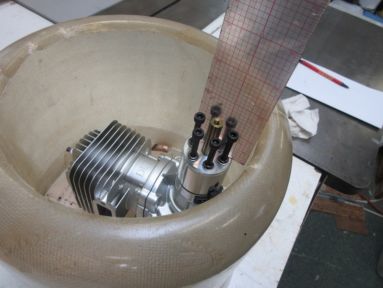
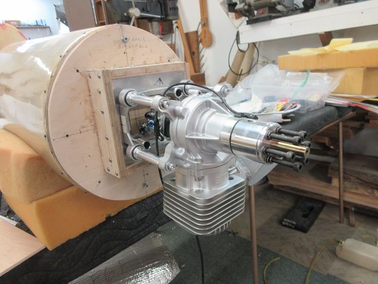
Engine mount (cont):
Hysol and plenty of screws. 1/2" thick baltic birch used.
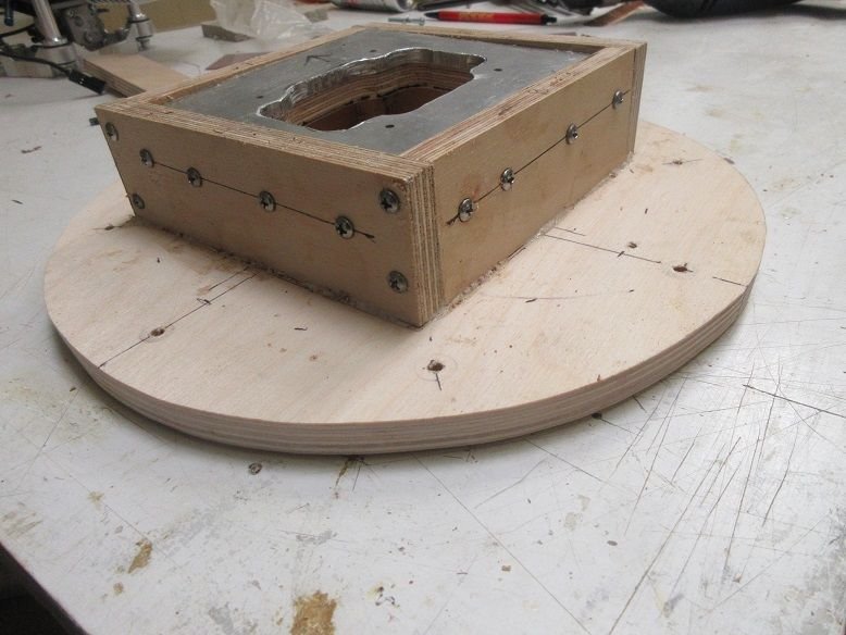
Back of removable fire wall.
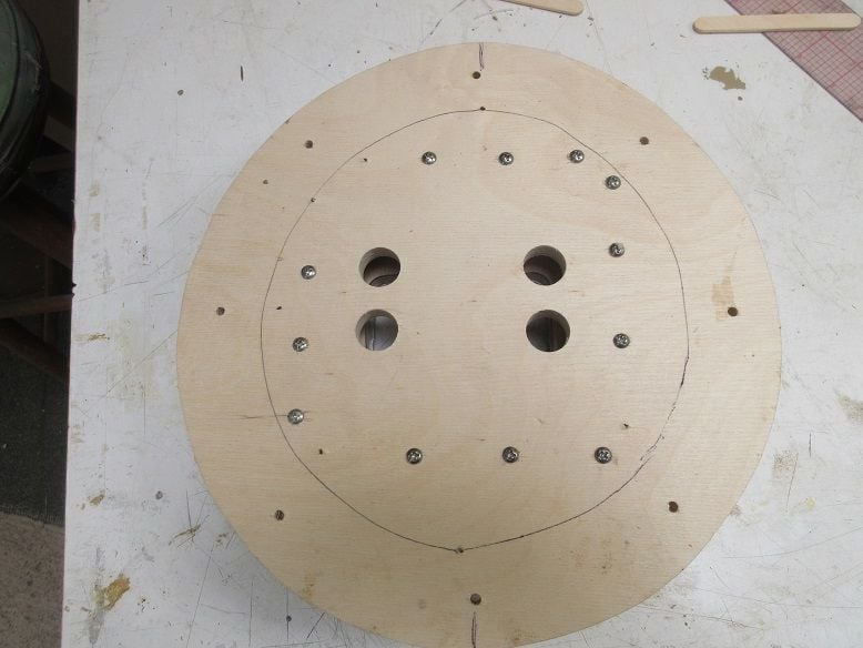
Dry fit the engine. Still need to drill holes to mount engine plus back trays for tank and servos.
Got the needed down and left thrust built into the face plate. The aluminum plate insures top mount is on one plane (geometrically) and the 1/2" thick baltic ply under the aluminum plate allows screws to be driven into the face plate.
After 60 something years of building things, i should have picked up a few 'good' habits' and probably have forgotten a few!
==============
Engine mount (cont):
Hysol and plenty of screws. 1/2" thick baltic birch used.
Back of removable fire wall.
Dry fit the engine. Still need to drill holes to mount engine plus back trays for tank and servos.
Got the needed down and left thrust built into the face plate. The aluminum plate insures top mount is on one plane (geometrically) and the 1/2" thick baltic ply under the aluminum plate allows screws to be driven into the face plate.
Last edited by samparfitt; 06-14-2020 at 06:02 AM.
06-14-2020, 06:20 AM
#18
Engine compartment (cont)
Sure get a lot of 'there is an issue processing the data'.
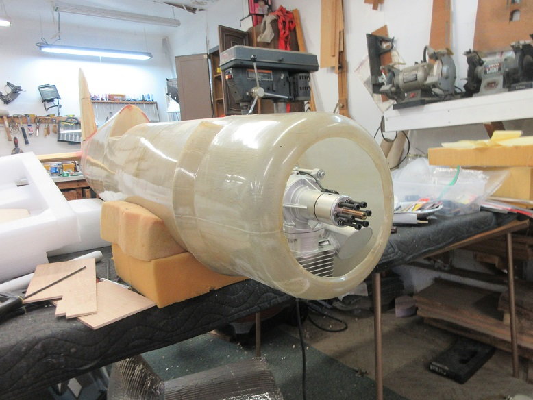
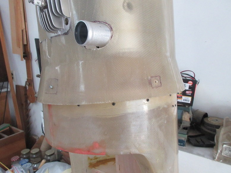
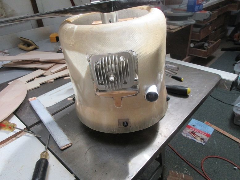
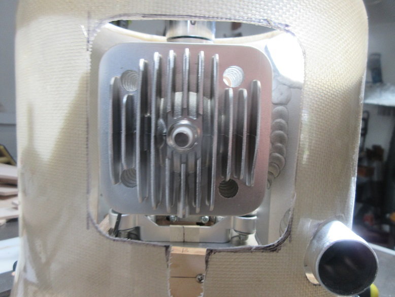
Cowl mount:
Once in awhile one gets lucky. With the stock muffler on, the cowl just fits. Much easier locating where to cut holes when one can see through the fiber glass!
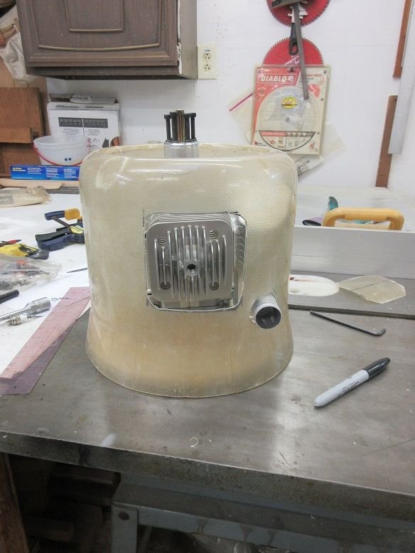
The muffler is really large.
Some extra cutting for the plug wire.
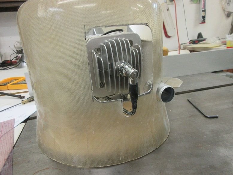
Nice that the plug wire is really long: maybe can mount ignition behind the fire wall.
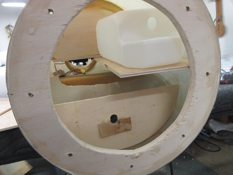
Initial setup of tank and servos.
In order to clear the fuse fire wall, some adjustments are needed.
Never mounted the tank 90 degree on it's side but no reason why it shouldn't work.
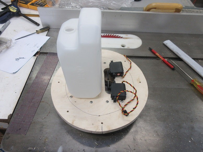
Servo tray. Four holes in each corner makes it easier to cut on the scroll saw.
In order to be able to remove the servos from the tray, since the tank tray will block access from the top, servos will be mounted from the bottom so eyelets reversed.
Dry fit.
Servos just fit. At worst, maybe a little trim on the fuse fire wall for the corners of the servos.
1/2" thick baltic birch ply used for supports of tank and servo trays.
Reverse mounting of servos to the tray.
Sure get a lot of 'there is an issue processing the data'.
Cowl mount:
Once in awhile one gets lucky. With the stock muffler on, the cowl just fits. Much easier locating where to cut holes when one can see through the fiber glass!
The muffler is really large.
Some extra cutting for the plug wire.
Nice that the plug wire is really long: maybe can mount ignition behind the fire wall.
Initial setup of tank and servos.
In order to clear the fuse fire wall, some adjustments are needed.
Never mounted the tank 90 degree on it's side but no reason why it shouldn't work.
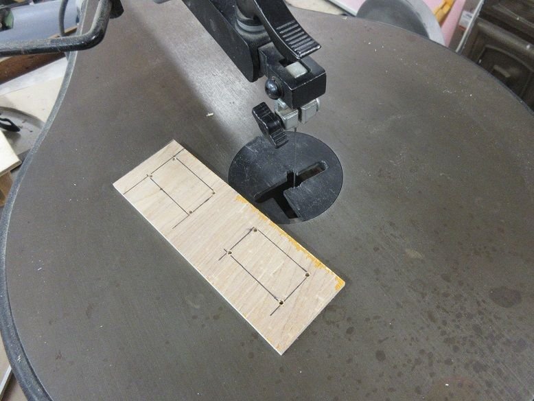
Servo tray. Four holes in each corner makes it easier to cut on the scroll saw.
In order to be able to remove the servos from the tray, since the tank tray will block access from the top, servos will be mounted from the bottom so eyelets reversed.
Dry fit.
Servos just fit. At worst, maybe a little trim on the fuse fire wall for the corners of the servos.
1/2" thick baltic birch ply used for supports of tank and servo trays.
Reverse mounting of servos to the tray.
Last edited by samparfitt; 06-14-2020 at 06:23 AM.
06-14-2020, 01:56 PM
#19
Removable fire wall.
Epoxied the throttle/choke servo tray and tank/igniton module/battery tray to the back of the removable fire wall.
Plenty of slot cut into the tray for straps to hold tank, module and battery.
A few pieces of wood under the servos to hold them until the epoxy dries.
Epoxied the throttle/choke servo tray and tank/igniton module/battery tray to the back of the removable fire wall.
Plenty of slot cut into the tray for straps to hold tank, module and battery.
A few pieces of wood under the servos to hold them until the epoxy dries.
06-14-2020, 04:52 PM
#20
Removable fire wall (cont).
I screwed that up!
Went to mount the removable fire wall on the fuse and it didn't fit. I forgot that the wing is very close to the fire wall so the tank wasn't going to 'make it'.
The last plane I did was a Z P-47 and no problem with that!
I used a heat gun to heat up the epoxy and the tank tray popped off.
A new tank tray was made that will be screwed onto the main service tray in the fuse. Fortunately, the main service tray had room at the front to mount the tank tray.
This puts the tank offset but I doubt if the lateral CG will be affected that much. Now the throttle/choke servos are on the right and the tank on the left half of the fuse.
This doesn't make the front totally modular but the tank, I can 'live' with it being separate as only a fuel line will need to be disconnected on the removable fire wall.
The big thing I hate is trying to adjust the throttle/choke servos from inside the fuse on a fixed fire wall.
The servos are easy to adjust when mounted on the removable fire wall. I can use some temporary wire extensions and, easily adjust the throttle/choke, visually while disconnected from the fuse.
40 oz tank: that should give me a 'few' minutes!
Double 4200 ma batteries up front for weight and safety: not spending hundreds of hours and thousands of dollars to risk using just one battery on the receiver.
I've seen several planes crash due to only one battery for the receiver (both lithium and nicads).
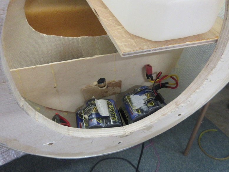
HEY, everything fits!
And I made sure the new ignition module/battery tray doesn't interferes with the tank!
Still have to make a 'weight' box over the engine.

I screwed that up!
Went to mount the removable fire wall on the fuse and it didn't fit. I forgot that the wing is very close to the fire wall so the tank wasn't going to 'make it'.
The last plane I did was a Z P-47 and no problem with that!
I used a heat gun to heat up the epoxy and the tank tray popped off.
A new tank tray was made that will be screwed onto the main service tray in the fuse. Fortunately, the main service tray had room at the front to mount the tank tray.
This puts the tank offset but I doubt if the lateral CG will be affected that much. Now the throttle/choke servos are on the right and the tank on the left half of the fuse.
This doesn't make the front totally modular but the tank, I can 'live' with it being separate as only a fuel line will need to be disconnected on the removable fire wall.
The big thing I hate is trying to adjust the throttle/choke servos from inside the fuse on a fixed fire wall.
The servos are easy to adjust when mounted on the removable fire wall. I can use some temporary wire extensions and, easily adjust the throttle/choke, visually while disconnected from the fuse.
40 oz tank: that should give me a 'few' minutes!
Double 4200 ma batteries up front for weight and safety: not spending hundreds of hours and thousands of dollars to risk using just one battery on the receiver.
I've seen several planes crash due to only one battery for the receiver (both lithium and nicads).
HEY, everything fits!
And I made sure the new ignition module/battery tray doesn't interferes with the tank!
Still have to make a 'weight' box over the engine.
Last edited by samparfitt; 06-14-2020 at 05:03 PM.
06-15-2020, 09:33 AM
#21

Impressive. I've never seen an open wing fiberglassed then covered before.
If it's not too late, you can balance the rudder on the hinge line with some lead weight. That will cut down on fishtailing at high speeds.
carl
If it's not too late, you can balance the rudder on the hinge line with some lead weight. That will cut down on fishtailing at high speeds.
carl
06-15-2020, 12:45 PM
#22
Thanks, Carl.
Every once in awhile, I do something right!
That makes two of us. All my previous wings have been fully sheeted and glassed. The Corsair is about the only high performance plane that I can think of that had cloth on the outer wings. I was going to just solartex the whole outer wings but thought the glassing would give it some extra strength in case I do something stupid.
Too late on the rudder.
===================
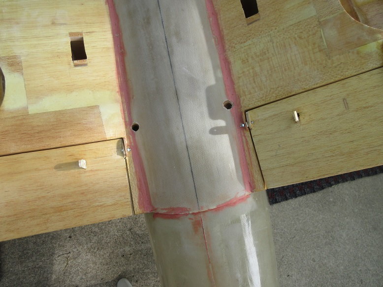
Tank tray (cont)
Glued a slotted piece of hard wood to the fuse to secure the front of the tray.
A couple button head screws to insure it doesn't come loose.
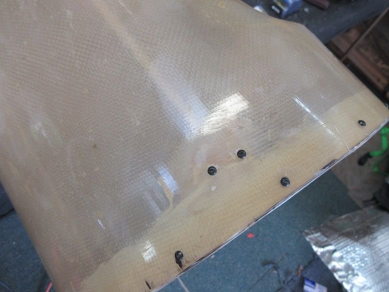
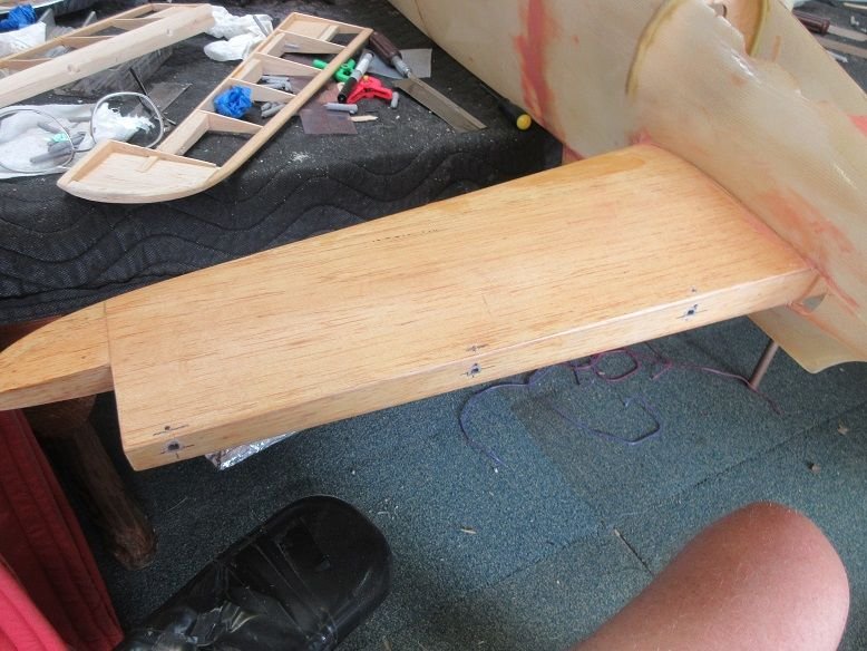
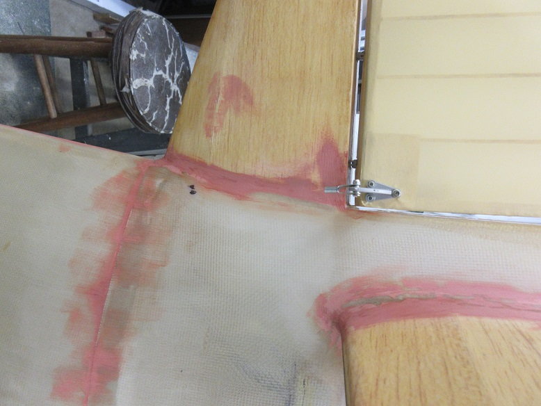
Center wing (cont)
The wing screws were missing so some were picked up at Fastenal. They have a great selection of bolts at reasonable prices plus there're 2 miles from my house!
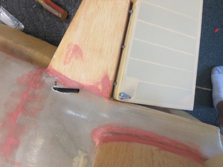
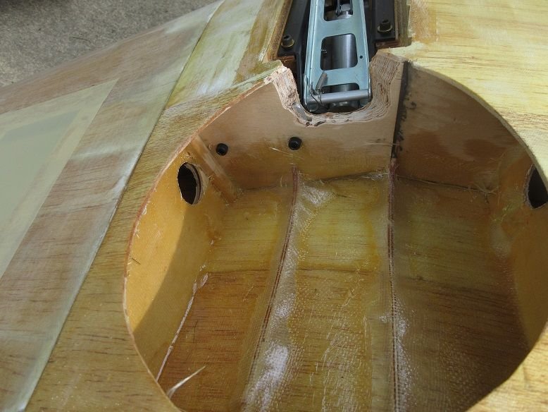
The original builder used flat metal (versus tubes) to secure the wings. With folding back retracts, probably no room for a tube.
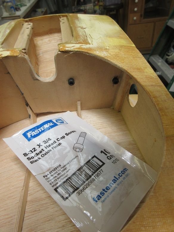
He used locking nuts on the opposite side.
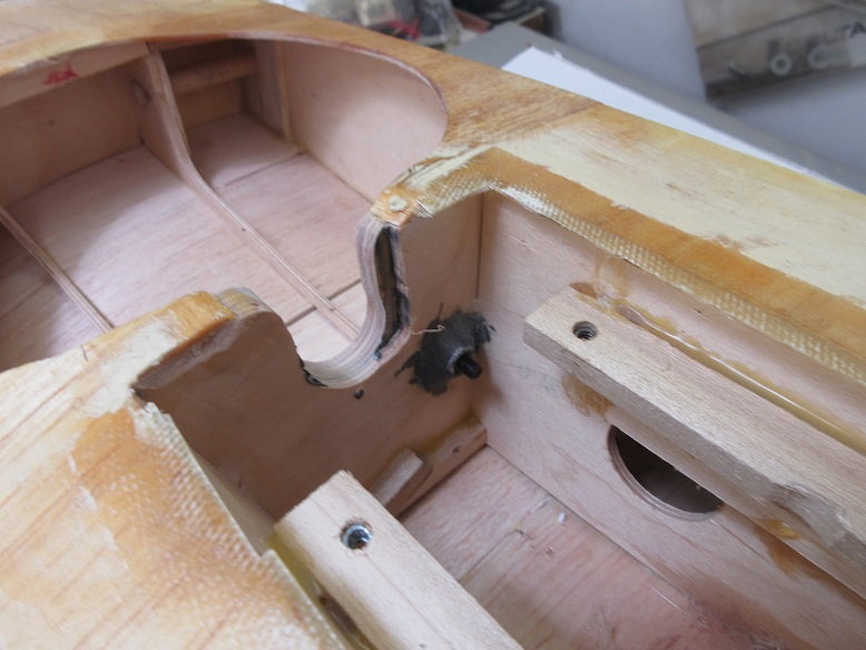
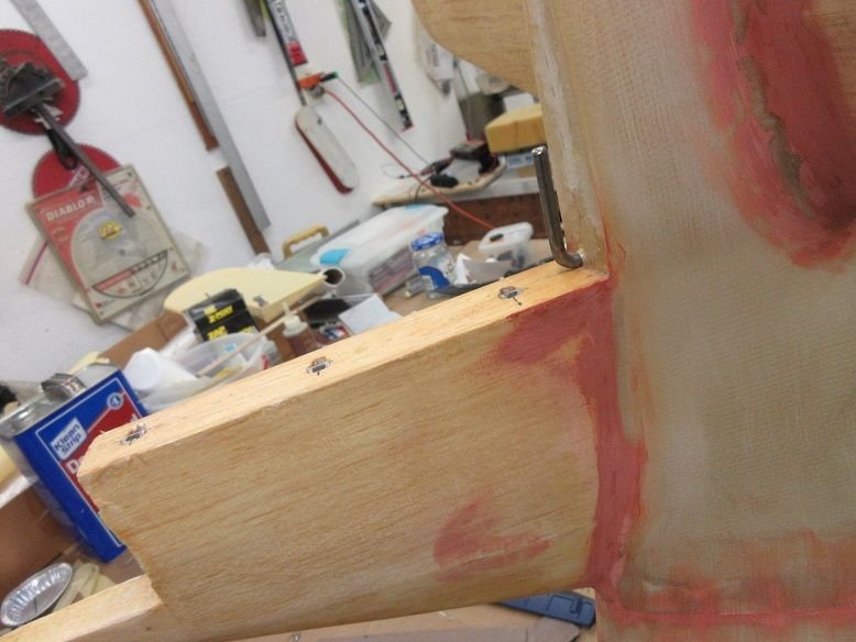
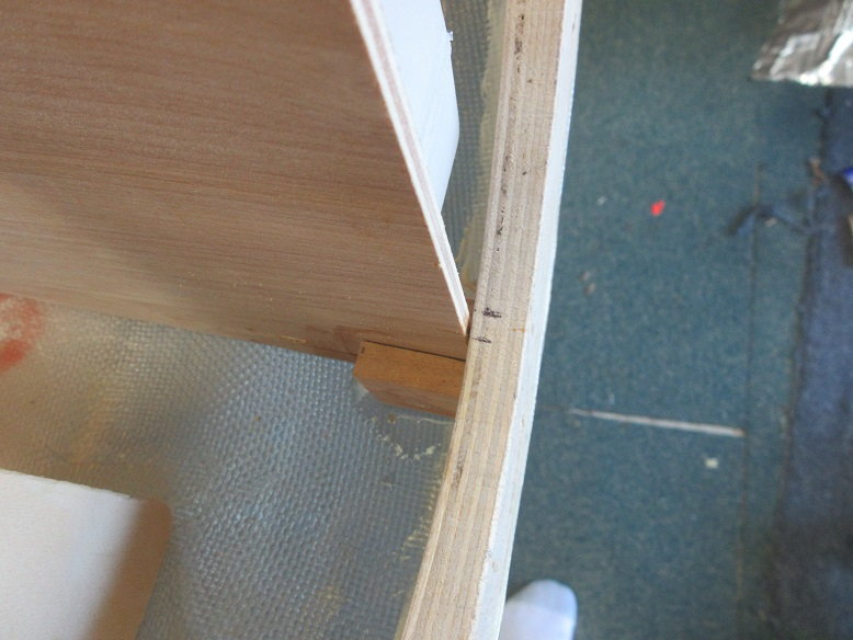
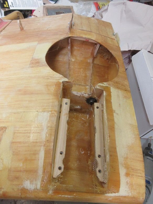
One of the retract wood mountings has damage on both ends. In stead of trying to remove it, I put a piece of 1/16" thick ply on the bottom.....

and used some Minwax wood filler. This is two part so extremely hard when dry and doesn't take long to harden. Used this on my daughter's window sills where there was some small rot and was impressed by the results.
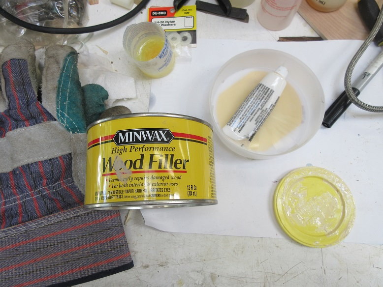
See last picture for results.
NOTE: another defect in the software on this site. Put the cursor at this location, uploaded the picture but was put at the end of the post. My other site does this, correctly.
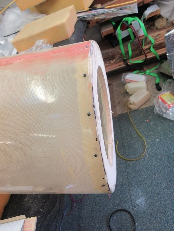
Some very heavy duty FG cloth from my local auto store to re-enforce the wheel well and gear mount area.
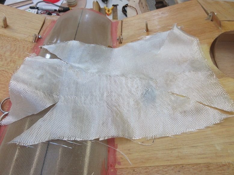
Corners cut to reduce wrinkles.
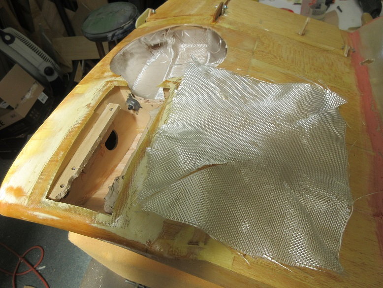
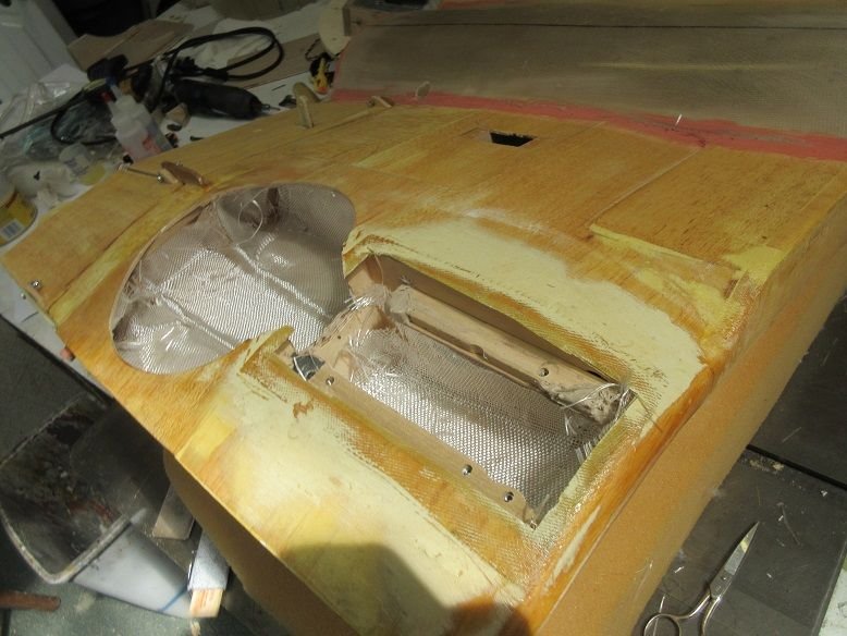
Some Zap finishing resin.
Some sanding and all should be good.
Every once in awhile, I do something right!
That makes two of us. All my previous wings have been fully sheeted and glassed. The Corsair is about the only high performance plane that I can think of that had cloth on the outer wings. I was going to just solartex the whole outer wings but thought the glassing would give it some extra strength in case I do something stupid.
Too late on the rudder.
===================
Tank tray (cont)
Glued a slotted piece of hard wood to the fuse to secure the front of the tray.
A couple button head screws to insure it doesn't come loose.
Center wing (cont)
The wing screws were missing so some were picked up at Fastenal. They have a great selection of bolts at reasonable prices plus there're 2 miles from my house!
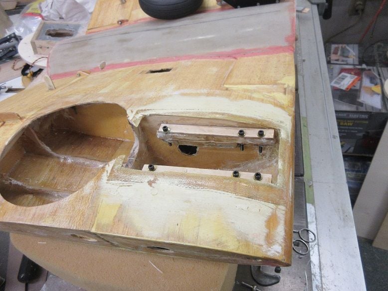
The original builder used flat metal (versus tubes) to secure the wings. With folding back retracts, probably no room for a tube.
He used locking nuts on the opposite side.
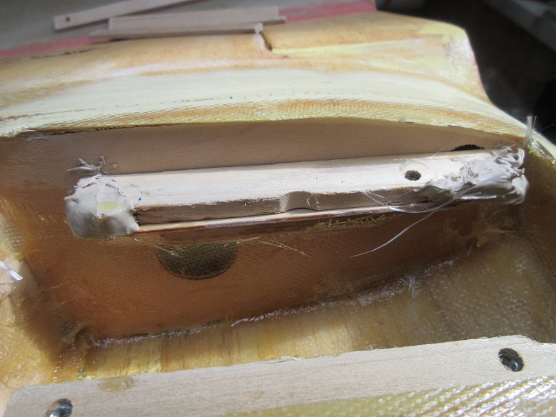
One of the retract wood mountings has damage on both ends. In stead of trying to remove it, I put a piece of 1/16" thick ply on the bottom.....
and used some Minwax wood filler. This is two part so extremely hard when dry and doesn't take long to harden. Used this on my daughter's window sills where there was some small rot and was impressed by the results.
See last picture for results.
NOTE: another defect in the software on this site. Put the cursor at this location, uploaded the picture but was put at the end of the post. My other site does this, correctly.
Some very heavy duty FG cloth from my local auto store to re-enforce the wheel well and gear mount area.
Corners cut to reduce wrinkles.
Some Zap finishing resin.
Some sanding and all should be good.
Last edited by samparfitt; 06-15-2020 at 05:07 PM.
06-15-2020, 05:18 PM
#23
NOTE: took 3 tries to finally get pictures to upload with out failure.
=================
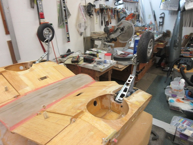
Center wing (cont)
Gear mounts (cont)
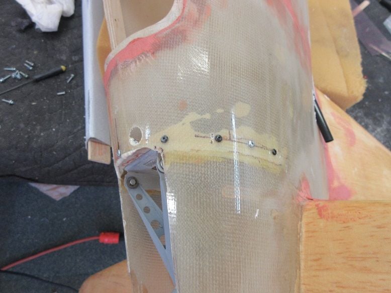
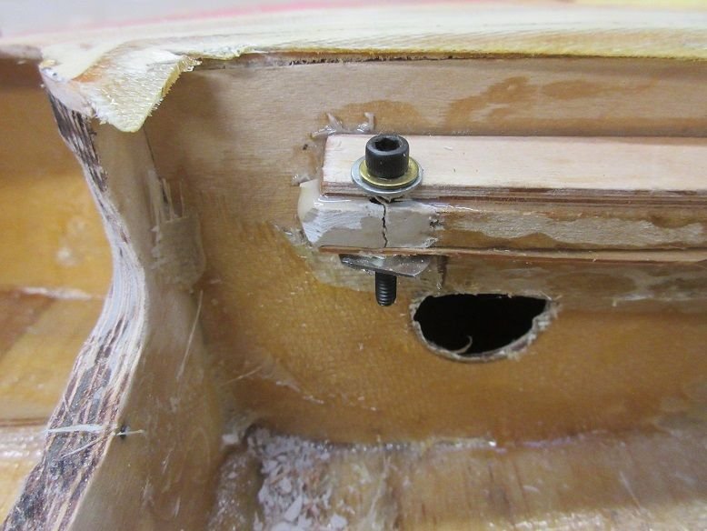
After the Minwax wood hardened, some 1/8" aircraft ply was epoxied along the top railings as the original railings look a little too thin plus it raised the gear enough so the wheels didn't touch the top of the wing in the UP position. #8X24 bolts.
The Minwax wasn't as tough as I thought as it cracked under the pressure of the screw bolt.
With the two end holes broken, new holes and blind nuts were used. All mounts have blind nuts for a good, secure fit.
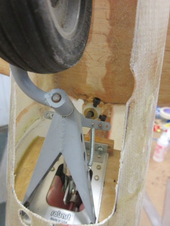
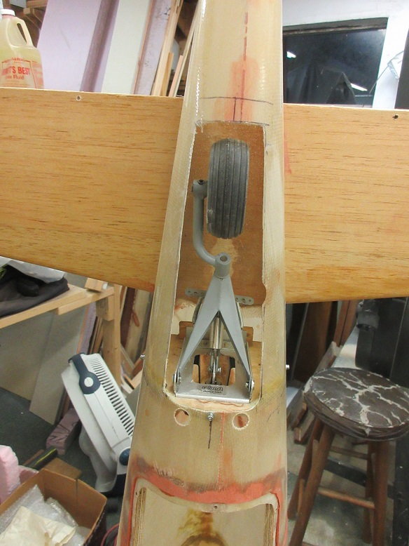
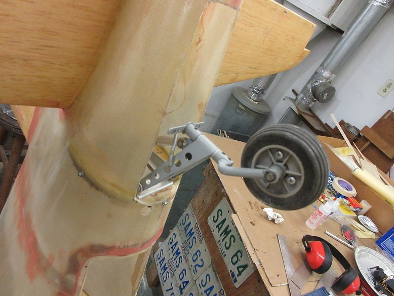
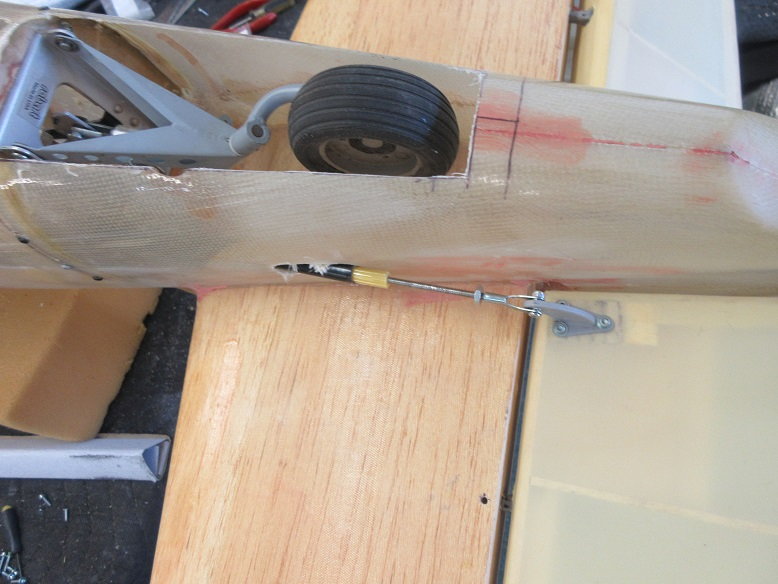
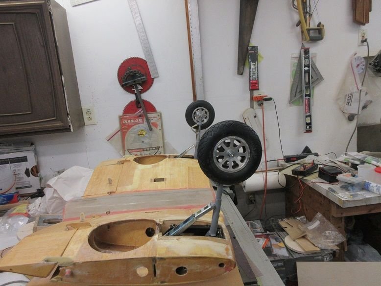
Manually, gear works well.
Gear in the UP position.
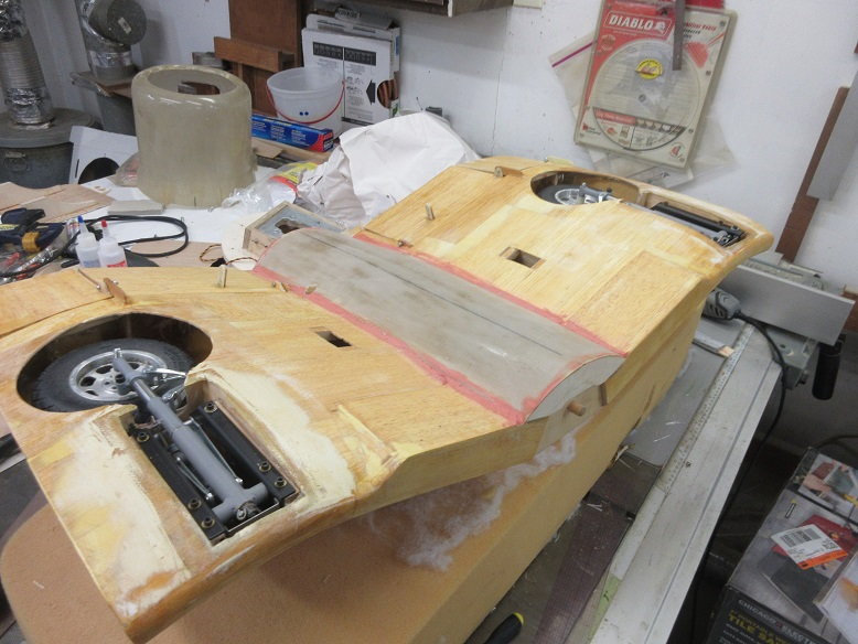
Down.
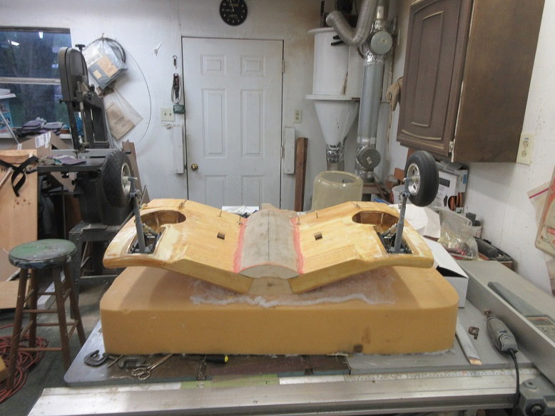
Could use some Corsair rims on those wheels!
Getting close to priming this baby. Think the only thing left is to mount the cowl.
=================
Center wing (cont)
Gear mounts (cont)
After the Minwax wood hardened, some 1/8" aircraft ply was epoxied along the top railings as the original railings look a little too thin plus it raised the gear enough so the wheels didn't touch the top of the wing in the UP position. #8X24 bolts.
The Minwax wasn't as tough as I thought as it cracked under the pressure of the screw bolt.
With the two end holes broken, new holes and blind nuts were used. All mounts have blind nuts for a good, secure fit.
Manually, gear works well.
Gear in the UP position.
Down.
Could use some Corsair rims on those wheels!
Getting close to priming this baby. Think the only thing left is to mount the cowl.
Last edited by samparfitt; 06-15-2020 at 05:21 PM.
06-16-2020, 04:07 PM
#24
Got some work done on the plane, late today.
Most of day spent getting a large tool chest for daughter's/son's dog grooming business (I'm the only one with a truck) and another 3 hours changing oil and detailing out daughter's car.
==========================
Engine compartment (cont).
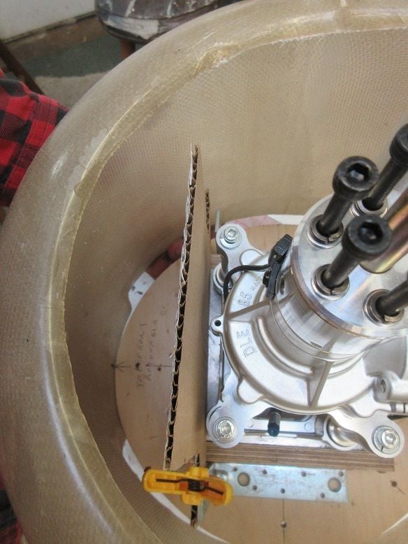
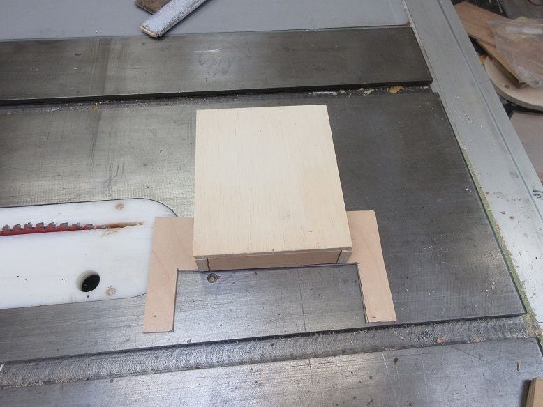
Making a weight box.
Made a cardboard template for testing. Had to shorten the length by an inch.
Two steel L brackets will secure the weight box to the fire wall.
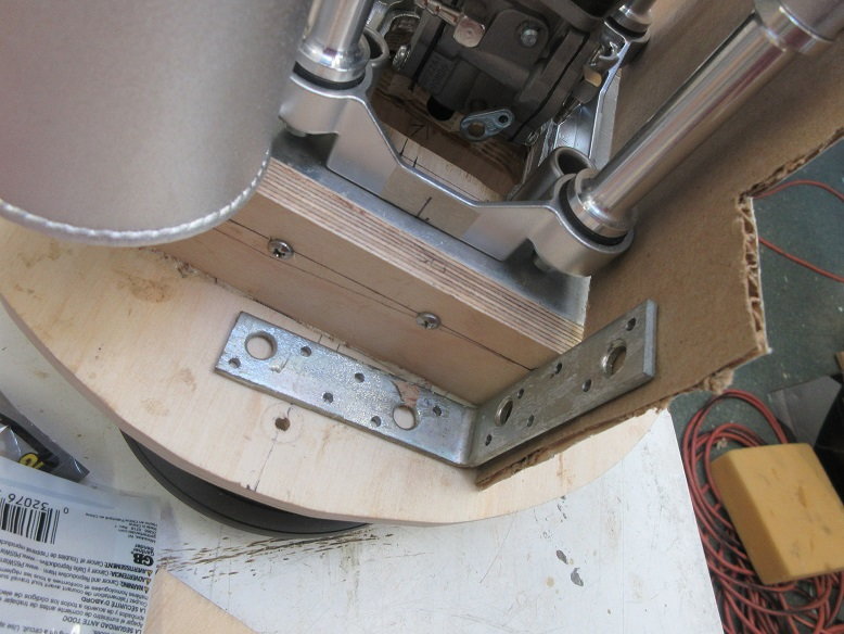
Looks like enough clearance to make an inch thick weight box.
Used template to cut some 1/8" thick aircraft ply.
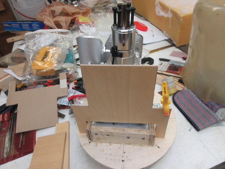
Some 1/4" thick baltic birch ply cut for the sides one inch high.
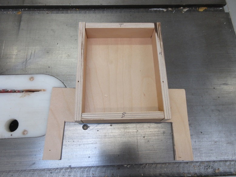
Removable top cover made.
Dry fit on fire wall.
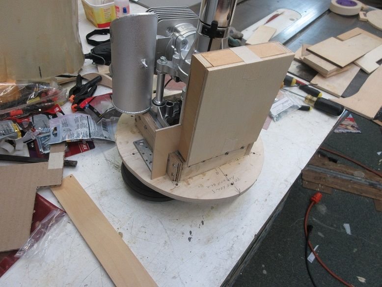
About a 1/4" clearance to the cowl.
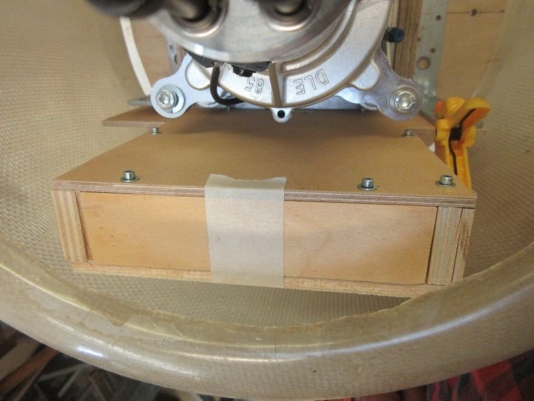
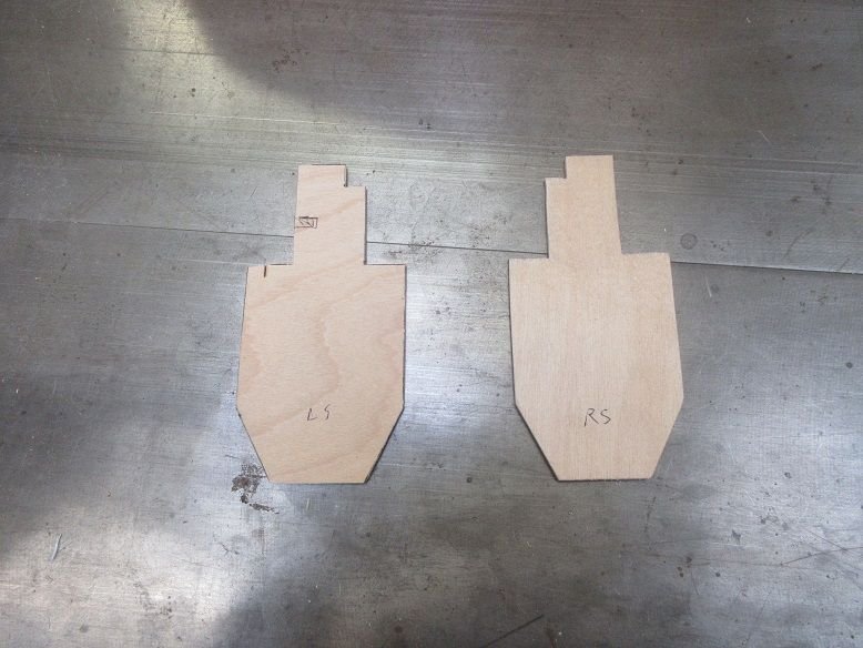
Some front doors cut out of 1/8" thick aircraft ply.
Most of day spent getting a large tool chest for daughter's/son's dog grooming business (I'm the only one with a truck) and another 3 hours changing oil and detailing out daughter's car.
==========================
Engine compartment (cont).
Making a weight box.
Made a cardboard template for testing. Had to shorten the length by an inch.
Two steel L brackets will secure the weight box to the fire wall.
Looks like enough clearance to make an inch thick weight box.
Used template to cut some 1/8" thick aircraft ply.
Some 1/4" thick baltic birch ply cut for the sides one inch high.
Removable top cover made.
Dry fit on fire wall.
About a 1/4" clearance to the cowl.
Some front doors cut out of 1/8" thick aircraft ply.
Last edited by samparfitt; 06-16-2020 at 04:11 PM.
06-17-2020, 02:05 PM
#25
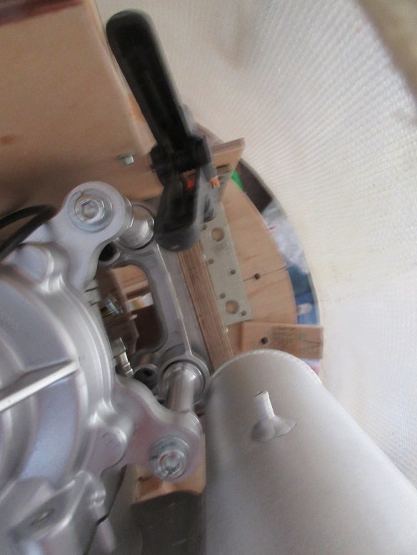
Cowl mounts:
Four wooden blocks are being used to hold the cowl to the fire wall.
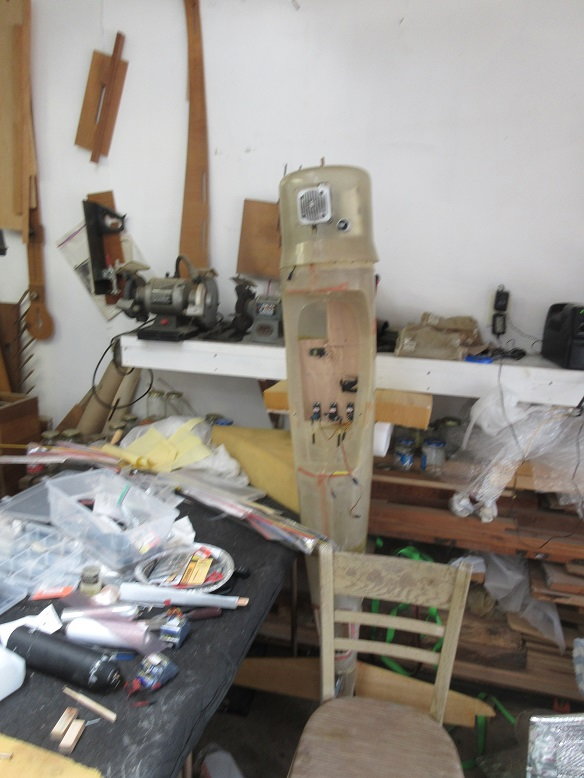
I used gravity to hold the cowl mounts in place by placing the fuse on it's tail.
Had to get a chair as the fuse is taller than me.
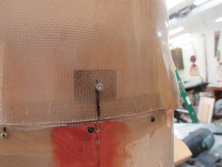
Top mount was done, first. For alignment and keeping the cowl in place, a small wood screw was used to secure the cowl to the fire wall.
The clear FG made it easy to align the mounts and drill holes.
Next mount done was the bottom mount: After a screw was used to secure the cowl to the mount, the two sides were done.
Each mount was epoxied in place with the fuse on it's tail greatly helping in keeping the mounts 'in place' until the epoxy dried.
Making sure the prop clears the cowl.
One of the side mounts.
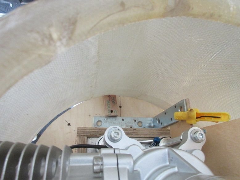
The other side mount. Had to place the mount below the weight box bracket.
Pilot holes drilled in the two side mounts.
Once all mounts were secured with epoxy, screws were used to, also, mechanically secure the mounts.
Mounts were drilled/tapped for 10X24 button head screws.
A trick my friend Scott showed me using a paper towel to give enough friction to hold a socket head screw.
Thought I'd assemble the plane to make sure all's good. Wing bolts only go into fuse 1/2" so will get some 3" long 1/4"X20X3", tomorrow.
Outer wing screws good.
Four wooden blocks are being used to hold the cowl to the fire wall.
I used gravity to hold the cowl mounts in place by placing the fuse on it's tail.
Had to get a chair as the fuse is taller than me.
Top mount was done, first. For alignment and keeping the cowl in place, a small wood screw was used to secure the cowl to the fire wall.
The clear FG made it easy to align the mounts and drill holes.
Next mount done was the bottom mount: After a screw was used to secure the cowl to the mount, the two sides were done.
Each mount was epoxied in place with the fuse on it's tail greatly helping in keeping the mounts 'in place' until the epoxy dried.
Making sure the prop clears the cowl.
One of the side mounts.
The other side mount. Had to place the mount below the weight box bracket.
Pilot holes drilled in the two side mounts.
Once all mounts were secured with epoxy, screws were used to, also, mechanically secure the mounts.
Mounts were drilled/tapped for 10X24 button head screws.
A trick my friend Scott showed me using a paper towel to give enough friction to hold a socket head screw.
Thought I'd assemble the plane to make sure all's good. Wing bolts only go into fuse 1/2" so will get some 3" long 1/4"X20X3", tomorrow.
Outer wing screws good.