TopRC giant P-47 Thunderbolt ARF
 05-08-2022, 05:51 PM
#151


I plan on checking out the gear and testing it well before installing it into the airplane and if the retract units need to replaced, then I will do that before final install.
You Grandfather's life lessons are on point and very true, Life is way too short! Too many airplanes/helicopters and not enough time!
If the CAD or .stl files for the Chin Scoop are available to share, then I could print a couple more out if anybody needed one for their airplane, either in Engineering Resin or PETG. I planned on designing my own with the help of Aircorps Library documentation, once the airplane got here, but no need to reinvent the wheel if the designer of the files is willing to share. Looks like a bunch of little fun items to design and modify.


 05-08-2022, 08:10 PM
#154
Thanks, they're 4-40. Only because I have a lot more SAE hardware around than metric. I installed all the stock 2mm stuff originally, but couldn't deal with the thought of screws that small on a 35+ lb plane.
05-08-2022, 08:20 PM
#155
If the CAD or .stl files for the Chin Scoop are available to share, then I could print a couple more out if anybody needed one for their airplane, either in Engineering Resin or PETG. I planned on designing my own with the help of Aircorps Library documentation, once the airplane got here, but no need to reinvent the wheel if the designer of the files is willing to share. Looks like a bunch of little fun items to design and modify.
 05-09-2022, 07:49 AM
#160
I did and it looks great, thanks for your help, I really appreciate it, I did let Geoff know that its for personal use, but I may print out a few for members here, no charge though, since its not my design. I am getting it sliced today and ready to print. I do want to confirm that the dimensions of the cowl where the top of the chin scoop attached is approximately 9"? I don't have one to compare to right now.
Hello Mike,
I am working on the settings for the chin scoop to help it print a little faster. Right now on the FDM machine, I am looking at 25 hours to print one, so these are going to take some time to print. But I am still working on slicer setting to speed it up, but still be strong. Talk soon.
Jason
I am working on the settings for the chin scoop to help it print a little faster. Right now on the FDM machine, I am looking at 25 hours to print one, so these are going to take some time to print. But I am still working on slicer setting to speed it up, but still be strong. Talk soon.
Jason
05-09-2022, 09:53 AM
#161
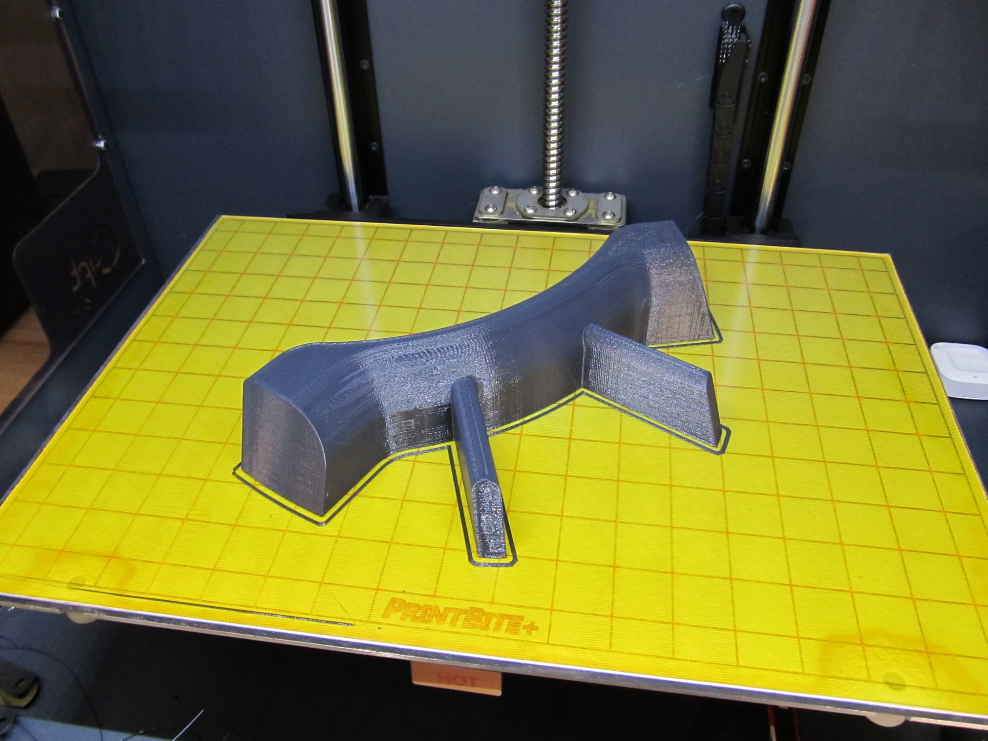
I was able to get the print down to nine hours. I tend to print at slower print speed, typically around 20 mm/s, that way there is virtually no finishing need for the finished part. However, the machine I am using is capable of much higher print speeds and since this part is not that complex, I increased the print speed up to 60 mm/s. This will needed to be fine-sanded, filled and painted to add final details, before installation, so the extra speed will work great. So far the print is looking good. I will send some pictures when finished, but here are a couple to start. Thanks.
Jason
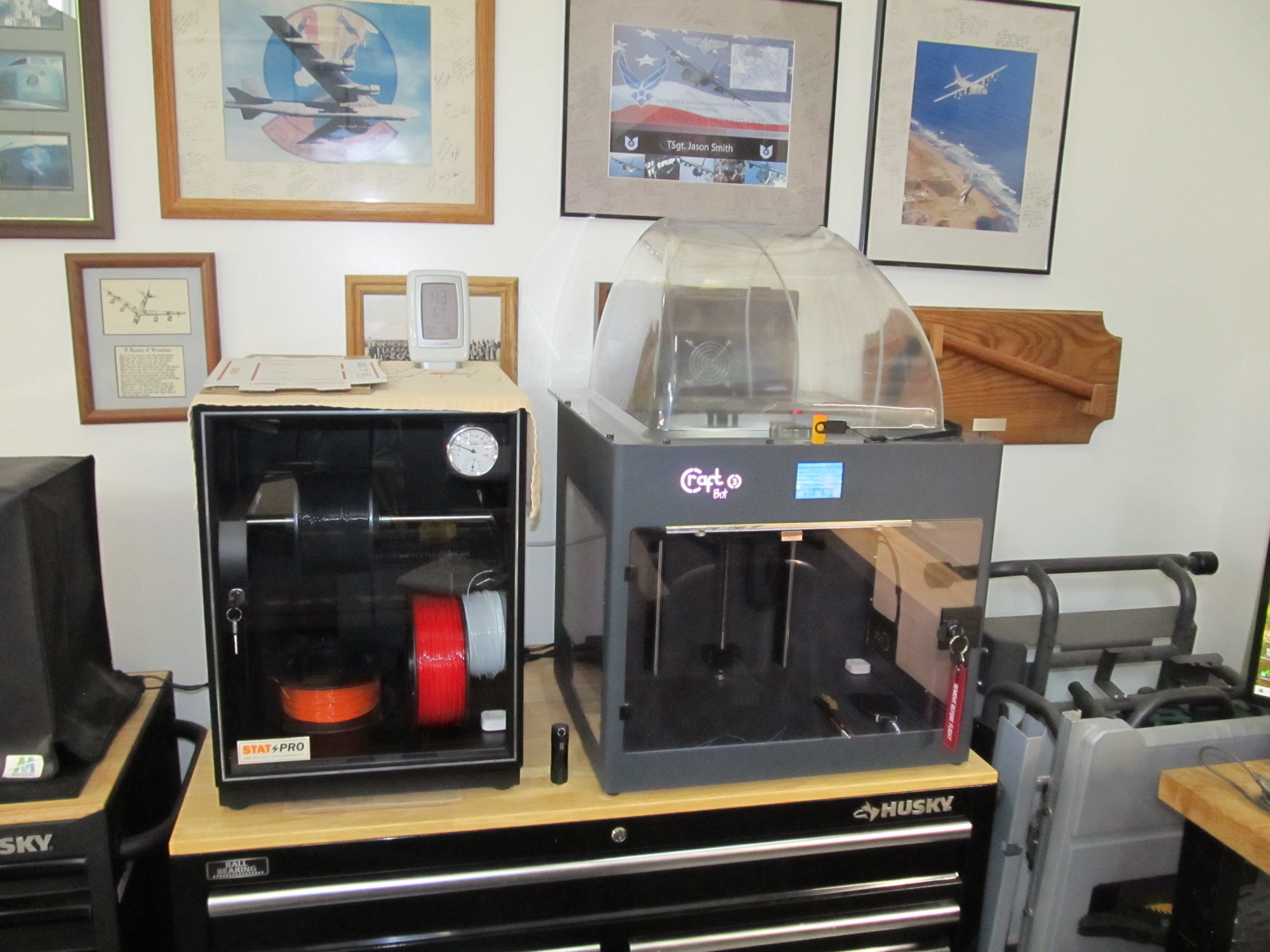
Craftbot 3 with StatPro Filament drying cabinet
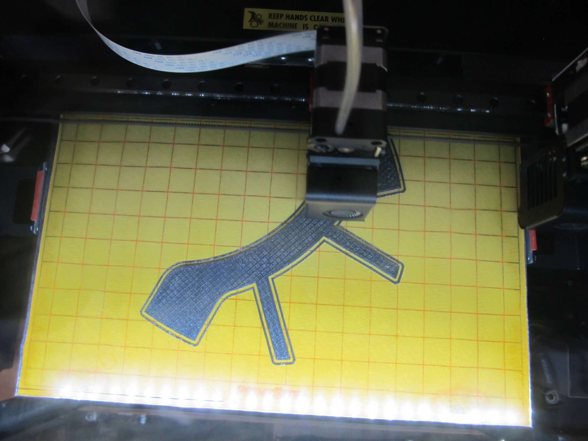
Top RC P-47 Chin Scoop designed by Geoff's son an printed in PETG.
Jason
Craftbot 3 with StatPro Filament drying cabinet
Top RC P-47 Chin Scoop designed by Geoff's son an printed in PETG.
05-09-2022, 06:53 PM
#162
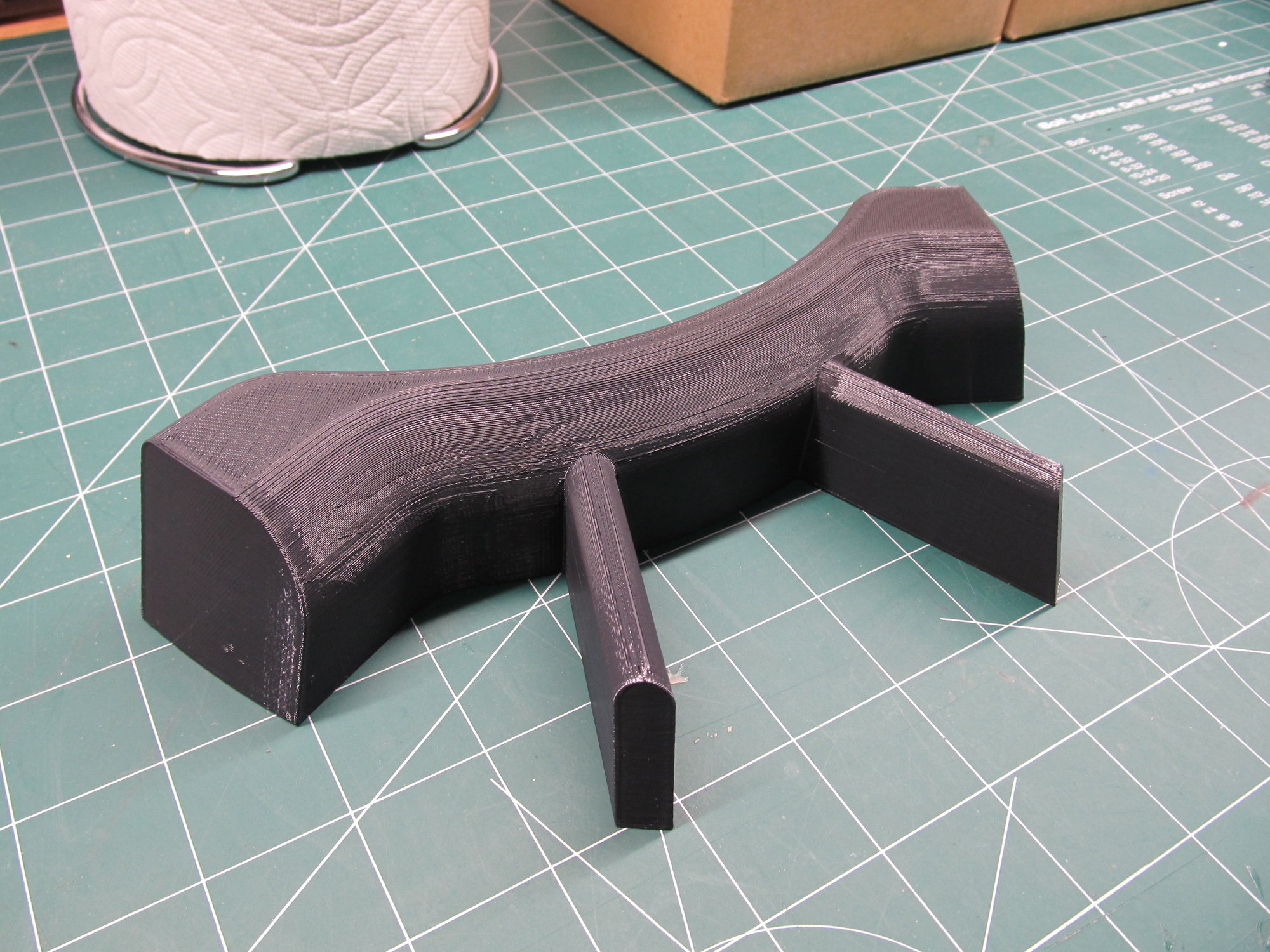
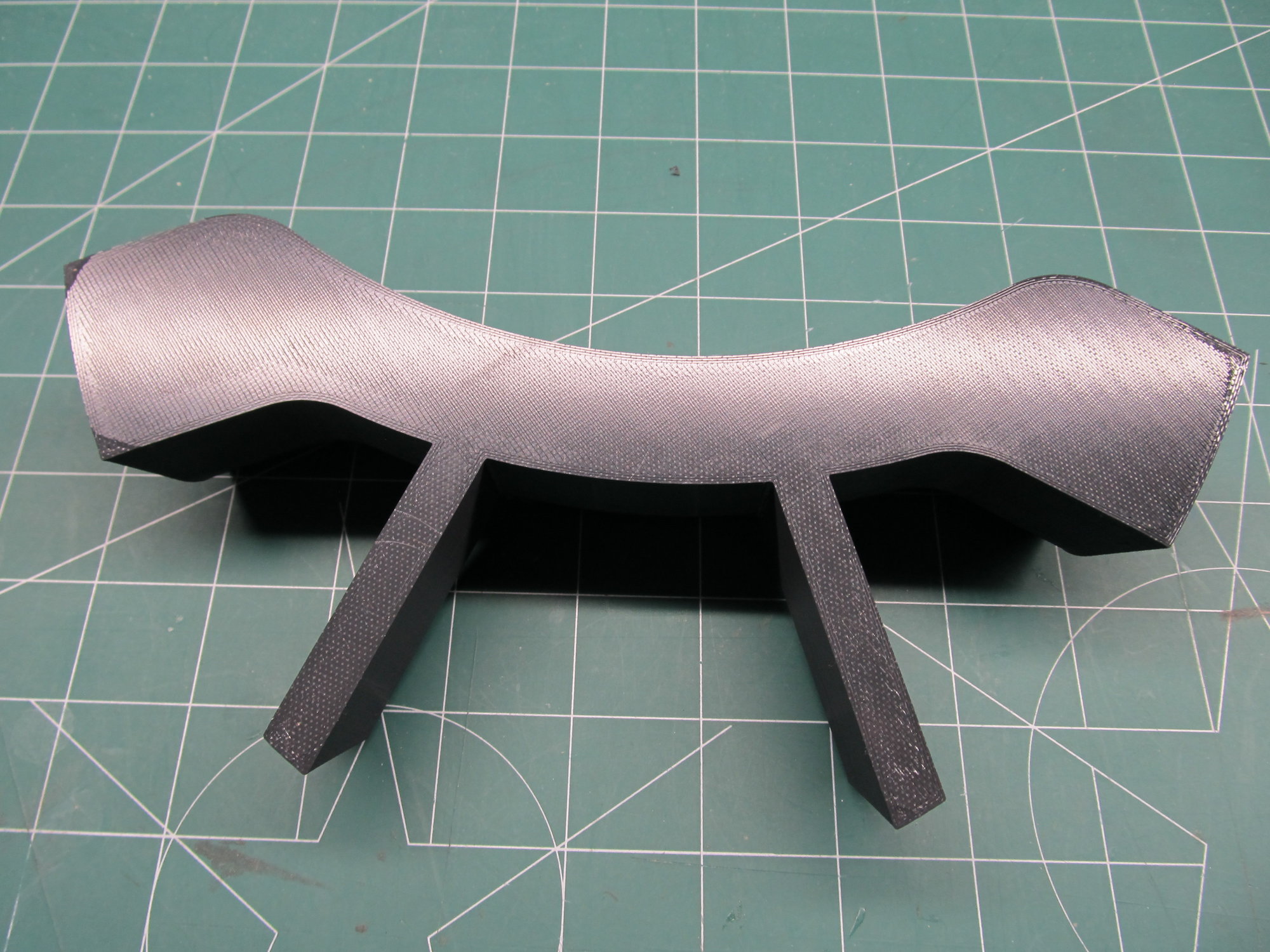
First Cowl/Chin Scoop is finished and it looks OK and certainly a useable part with a little sanding, filler, and primer. There where a few imperfections in the print and the edges lifted a little in the corner(s). But, I did increase the speed three times and I normally print with a raft with larger parts to help prevent lifting in the corners, but I figured that faced aft in the cowl, so not a huge deal if there was some minor lifting if there was. I could have also used a brim to help the stick in the corners. Many ways to skin a cat, so to speak.
Total weight was 6 oz, so it has some weight with the 40% infill. Might try and cut that down, but I am sure this airplane will need some nose weight. I thought about modifying the design to add pockets in the aft side of the print to accommodate weights if needed. But adding nose weight is the last resort!
Anyways, this one will go to Colt4570 if he wants it with the imperfections and I will print Mike's tomorrow and get them shipped off. I will contact both you guys to get shipping addresses. Thanks.
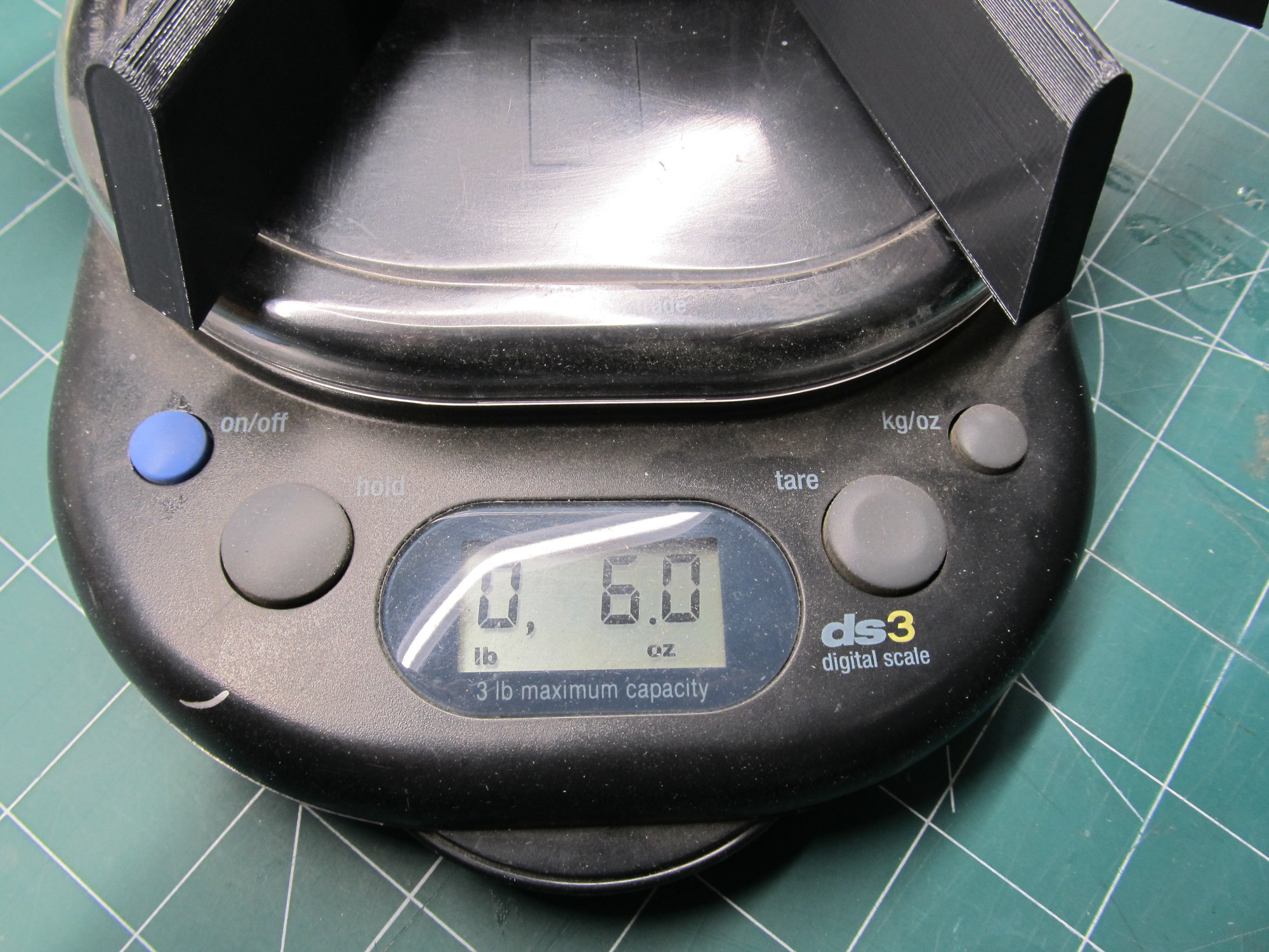
Last edited by JRSmith; 05-09-2022 at 06:58 PM.
The following users liked this post:
bradley (05-09-2022)
05-09-2022, 07:09 PM
#163
QUOTE=JRSmith;12727198]I was able to get the print down to nine hours. I tend to print at slower print speed, typically around 20 mm/s, that way there is virtually no finishing need for the finished part. However, the machine I am using is capable of much higher print speeds and since this part is not that complex, I increased the print speed up to 60 mm/s. This will needed to be fine-sanded, filled and painted to add final details, before installation, so the extra speed will work great. So far the print is looking good. I will send some pictures when finished, but here are a couple to start. Thanks.
Jason
Craftbot 3 with StatPro Filament drying cabinet
Top RC P-47 Chin Scoop designed by Geoff's son an printed in PETG.[/QUOTE]
BTW. Designer of this Intercooler for the P47 is "Tom Dryer".
Tom is the son of my fellow club member, Geoff Dryer.
Brad
Jason
Craftbot 3 with StatPro Filament drying cabinet
Top RC P-47 Chin Scoop designed by Geoff's son an printed in PETG.[/QUOTE]
BTW. Designer of this Intercooler for the P47 is "Tom Dryer".
Tom is the son of my fellow club member, Geoff Dryer.
Brad
05-09-2022, 07:17 PM
#164
Oh my gosh Jason, that looks fantastic! I would absolutely be happy to make use of that, but I can't ask you to make something like that for nothing. I would be happy to compensate you for it. If you want to PM me we can talk.
Thanks,
Darrin
Thanks,
Darrin
05-10-2022, 05:21 AM
#165
Thanks, I believe its a usable piece, I think I just printed it too fast and I could improve the quality with a couple more tweaks and sacrifice more time on the machine. However, this is a very smooth piece and will need to be sanded and finished anyways and the slight lifting in the corners is aft, so that is a non issue as well.
I appreciate the offer to pay. However, I can not accept any money for this, I am not the designer of the part and I asked for this file for personal use only. I did write that I would print a few for people in the thread if they wanted. I don't want to step on any toes and Tom Dryer did very nice work with the file. These will be the only two I will make for you and Mike and I will not longer offer them. I will design my own parts going forward for this model. Thanks.
05-10-2022, 11:07 AM
#166
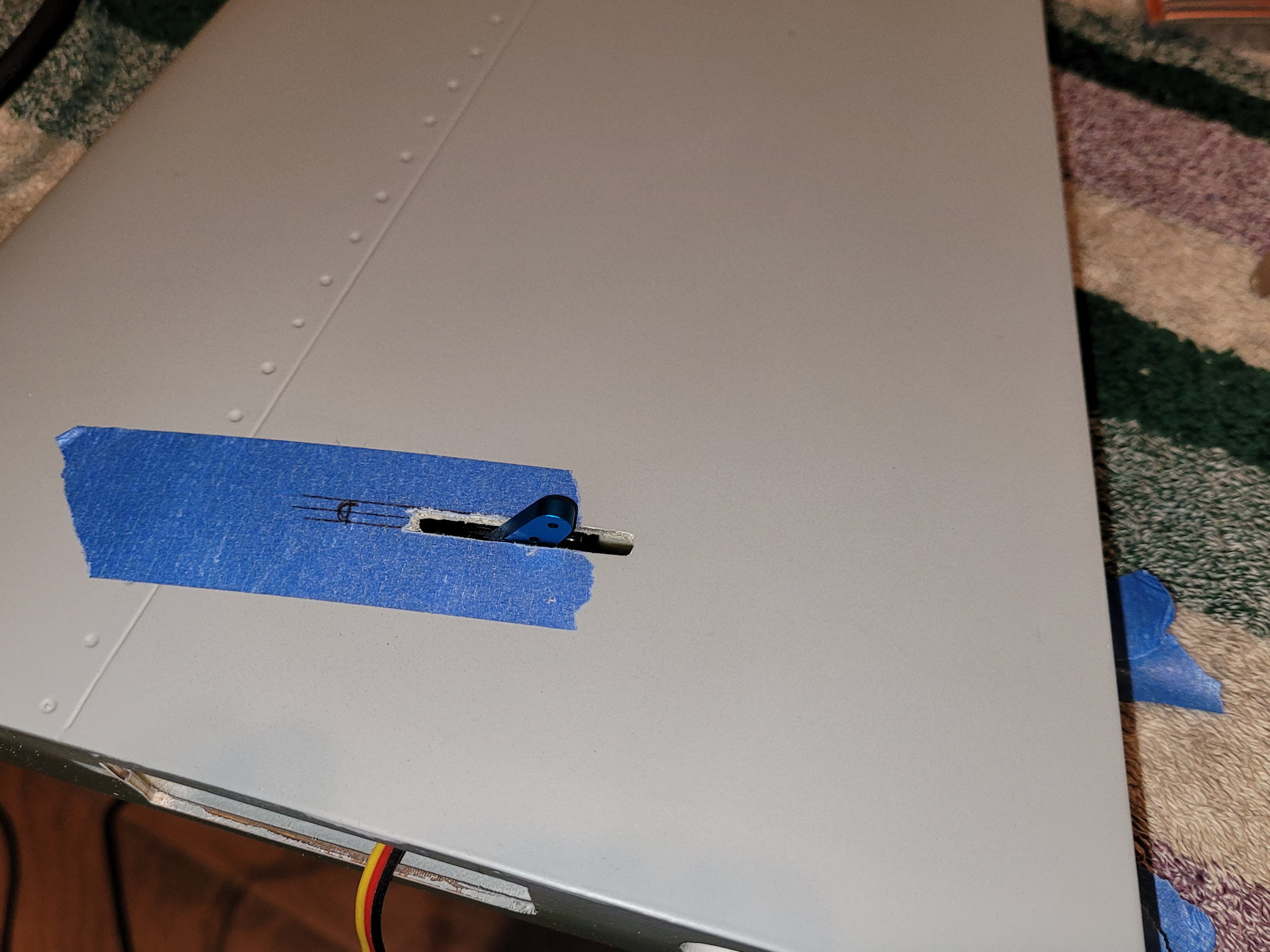
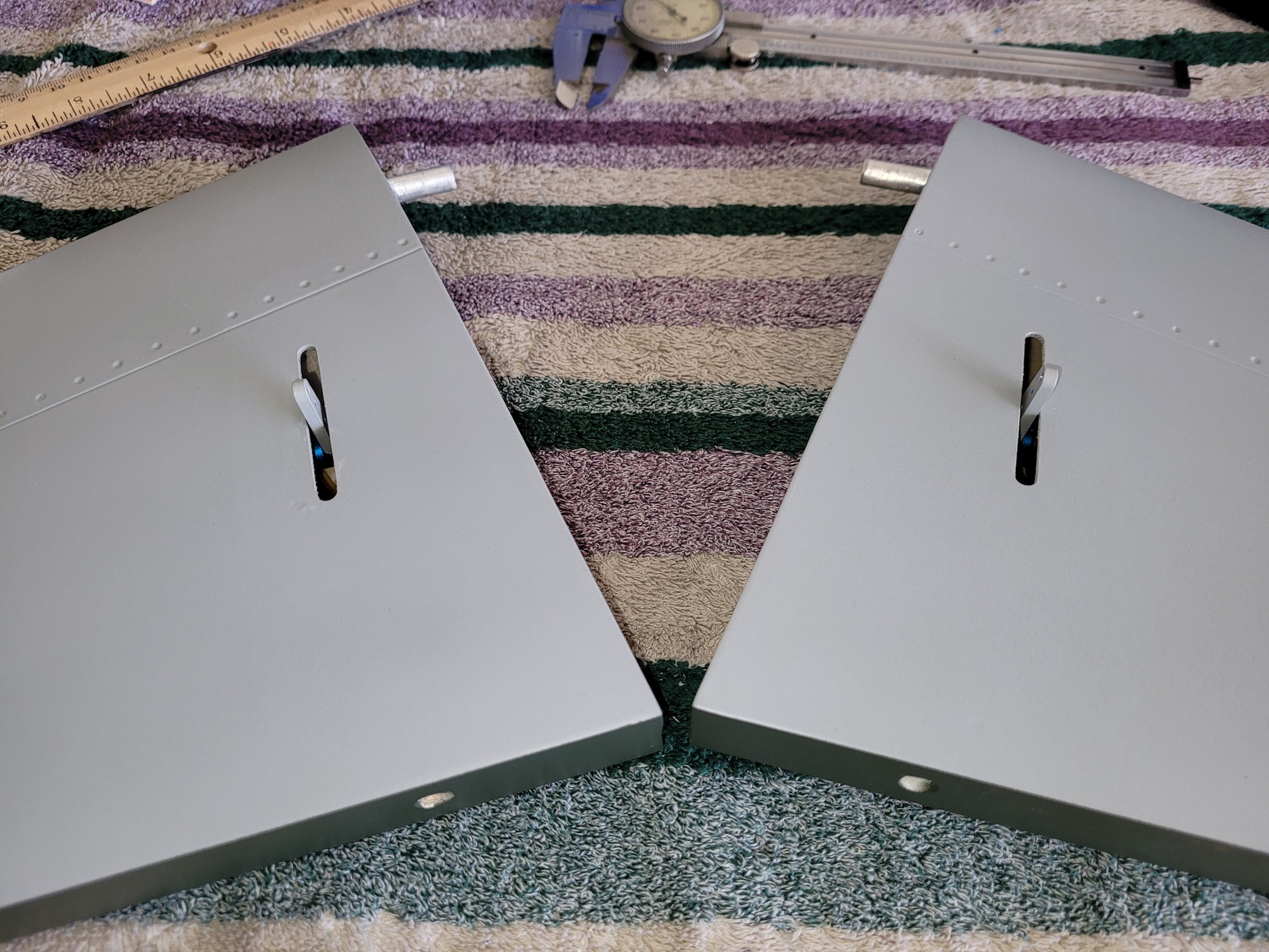
Thanks Mike! I just finished the hinges on the left wing as well. For whatever reason, having them recessed like that was also the only way I could get the bay door inboard far enough when opened and out of the way for the gear to clear it when extending.
On another note, every time I handle the fuse to work on it, the sides flexing make me want to remove the cockpit and add formers behind the turtle deck.. Has anyone else done any reinforcing?
Darrin
On another note, every time I handle the fuse to work on it, the sides flexing make me want to remove the cockpit and add formers behind the turtle deck.. Has anyone else done any reinforcing?
Darrin
Darrin, I�ve found the same with the flexible bit. Also noticed that the wood former that goes across the fuse under the cockpit was barely glued in and not at all on one side - so I reached in and pulled on it and it broke away really easily cracking the fuse about 1/2� long.

The only way I can think of to get in there to fix this properly and also do any other reinforcing would be to cut the cockpit tub out. So scratching my head on how to do that�.
Slow progress on the build for me. Lotsa conflicting projects non rc related. On a good note I did start bench running the 125�.
Cheers,
Paul
The following users liked this post:
bradley (05-10-2022)
05-10-2022, 12:22 PM
#167
Darrin,
Thanks, I believe its a usable piece, I think I just printed it too fast and I could improve the quality with a couple more tweaks and sacrifice more time on the machine. However, this is a very smooth piece and will need to be sanded and finished anyways and the slight lifting in the corners is aft, so that is a non issue as well.
I appreciate the offer to pay. However, I can not accept any money for this, I am not the designer of the part and I asked for this file for personal use only. I did write that I would print a few for people in the thread if they wanted. I don't want to step on any toes and Tom Dryer did very nice work with the file. These will be the only two I will make for you and Mike and I will not longer offer them. I will design my own parts going forward for this model. Thanks.
Thanks Jason, I understand now.
05-10-2022, 01:30 PM
#168
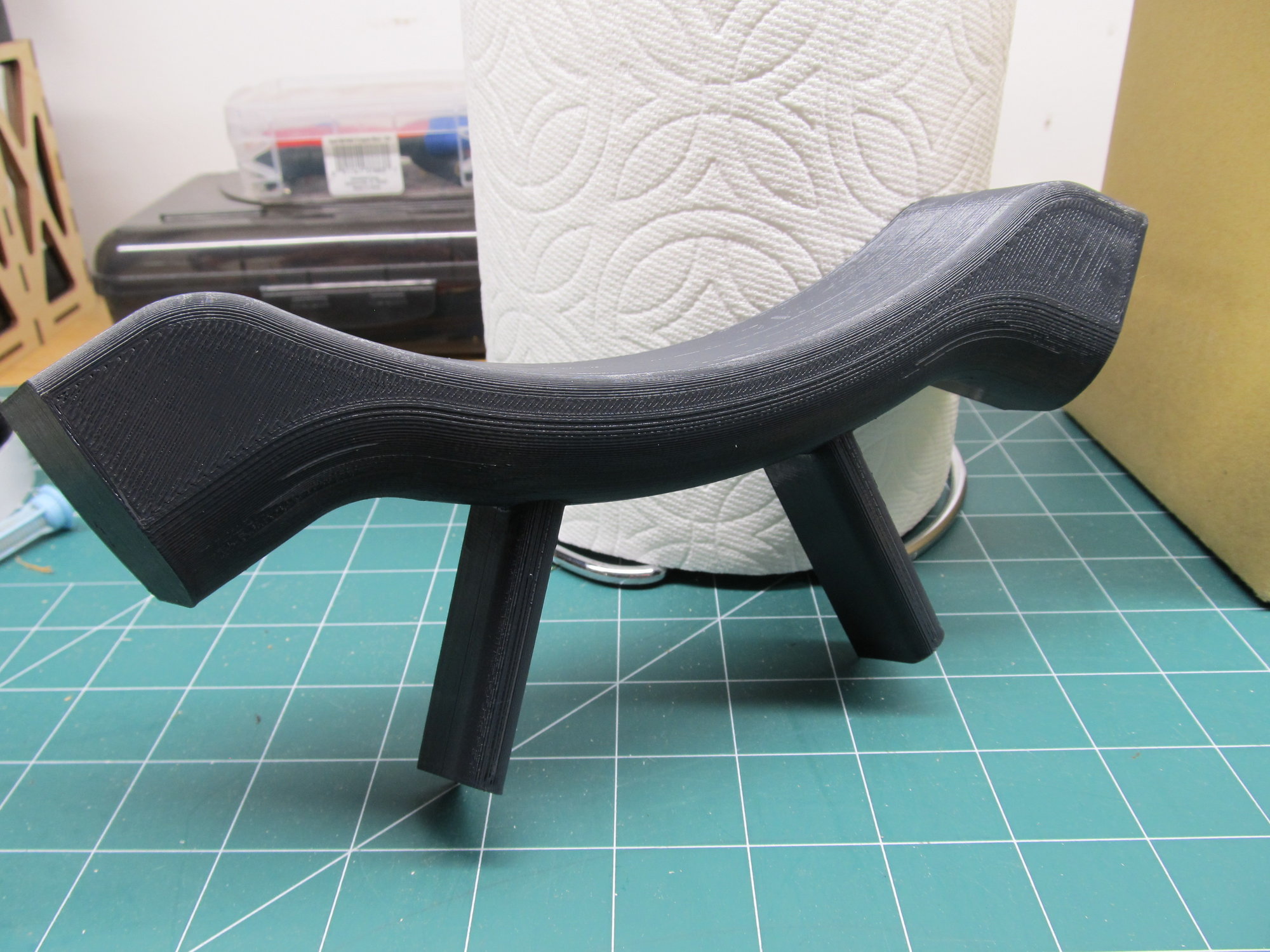
Hey guys, I�ve got the other piece that was printed by Tom/Geoff. I think the infill could be reduced to make a lighter part. There�s no structural requirements and it�s pretty solid as is.
pic of mine mocked up in the cowl with the 125 UMS. Will probably trim it down a bit to locate it better.
PaulD
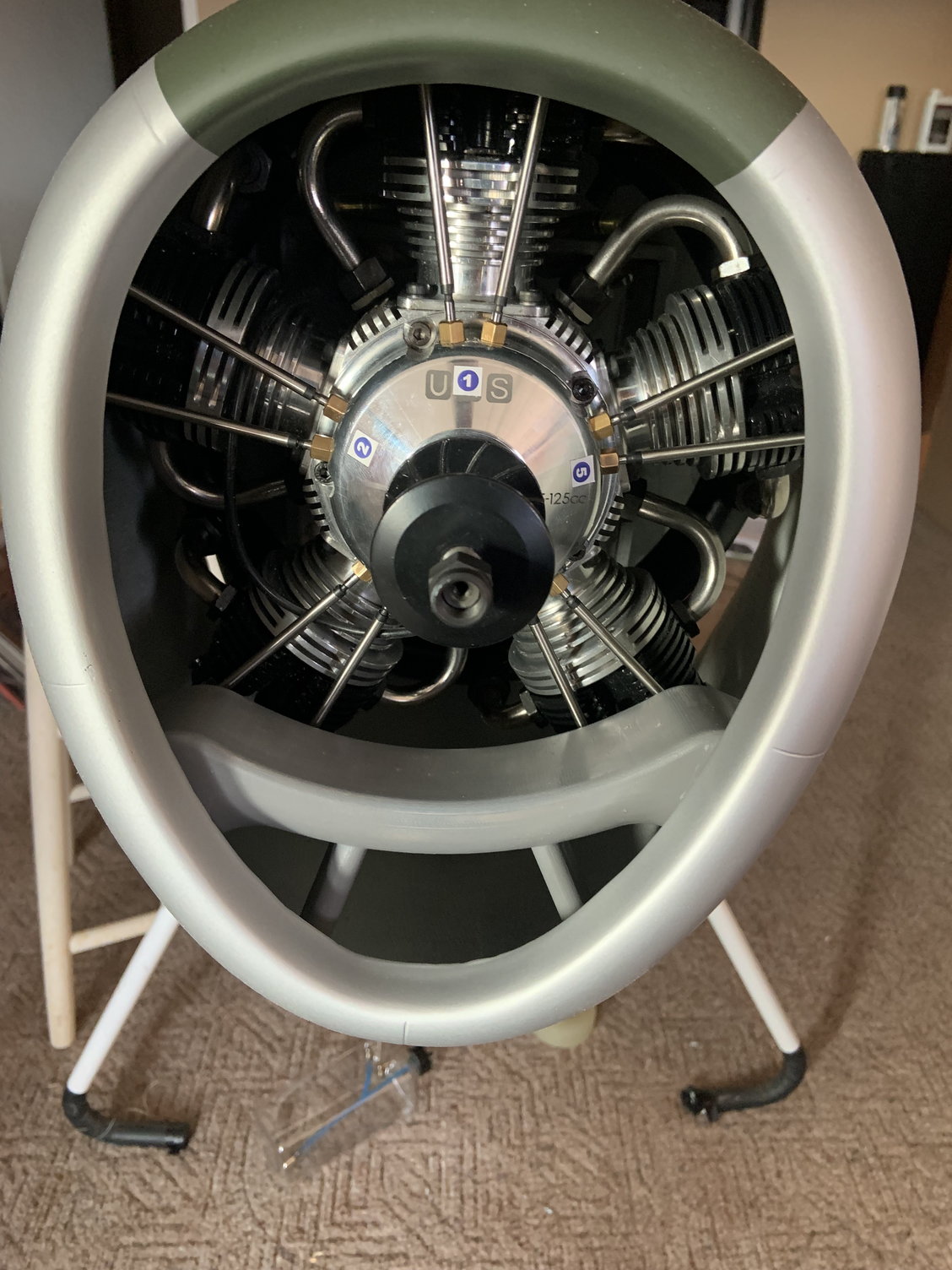
pic of mine mocked up in the cowl with the 125 UMS. Will probably trim it down a bit to locate it better.
PaulD
The following users liked this post:
bradley (05-10-2022)
05-10-2022, 07:03 PM
#169
I hope I did not write something wrong. I never claimed that I designed this and have always given credit to the designer as I should. However, I did not have Tom Dryer's name at the time and thank you for providing that. I should have asked Geoff what his son's name was so I could have given complete and due credit. My sincere apologies.
Darrin,
Thanks, I believe its a usable piece, I think I just printed it too fast and I could improve the quality with a couple more tweaks and sacrifice more time on the machine. However, this is a very smooth piece and will need to be sanded and finished anyways and the slight lifting in the corners is aft, so that is a non issue as well.
I appreciate the offer to pay. However, I can not accept any money for this, I am not the designer of the part and I asked for this file for personal use only. I did write that I would print a few for people in the thread if they wanted. I don't want to step on any toes and Tom Dryer did very nice work with the file. These will be the only two I will make for you and Mike and I will not longer offer them. I will design my own parts going forward for this model. Thanks.
Tom and Geoff sent me 3D details tonight. Greek to me, but here it is;
Brad
PrusaSlicer 0.15 OPTIMAL preset
fill density: 10%
fill pattern: support cubic
solid layers bottom: 2
combine infill every: 2 layers
61g, 4h 38m
Last edited by bradley; 05-10-2022 at 07:06 PM.
05-10-2022, 07:22 PM
#170
Sorry guys to have clogged up this thread with all my stuff, I will move on. Sorry again, I totally did NOT claim credit for the design.
Darrin and Mike, I was only trying to help and I never asked for any compensation, but it might be best if I don't send the parts, I have already deleted the files. This is why I design all parts myself. Thanks and take care guys, best of flying to you all.
Last edited by JRSmith; 05-10-2022 at 07:27 PM.
05-10-2022, 08:30 PM
#171
I thought I gave him credit, I just did not use his name directly. I never said I designed this part.
Sorry guys to have clogged up this thread with all my stuff, I will move on. Sorry again, I totally did NOT claim credit for the design.
Darrin and Mike, I was only trying to help and I never asked for any compensation, but it might be best if I don't send the parts, I have already deleted the files. This is why I design all parts myself. Thanks and take care guys, best of flying to you all.
update
Designer is offering the file for free to anyone now he tells me.
05-11-2022, 12:16 PM
#172
Darrin, I�ve found the same with the flexible bit. Also noticed that the wood former that goes across the fuse under the cockpit was barely glued in and not at all on one side - so I reached in and pulled on it and it broke away really easily cracking the fuse about 1/2� long.
The only way I can think of to get in there to fix this properly and also do any other reinforcing would be to cut the cockpit tub out. So scratching my head on how to do that�.
Slow progress on the build for me. Lotsa conflicting projects non rc related. On a good note I did start bench running the 125�.
Cheers,
Paul
Darrin