


MOKI RADIAL Care and Maintenence
 12-13-2020, 08:09 AM
#4526
Junior Member
Okay guys , I have read a lot on this thread and want to throw out this question:
What is the best ignition for the Moki 150/180 engine? Rainbow or CH Ignitions ?
What does each ignition setup require ?
Type of Plugs
Fuel Pump
Battery sizes
I am assuming that the Top Hat is inferior or has had past problems which required replacement / upgrade to one of these two ignitions.
What is the best ignition for the Moki 150/180 engine? Rainbow or CH Ignitions ?
What does each ignition setup require ?
Type of Plugs
Fuel Pump
Battery sizes
I am assuming that the Top Hat is inferior or has had past problems which required replacement / upgrade to one of these two ignitions.
 12-13-2020, 08:40 AM
#4527

Okay guys , I have read a lot on this thread and want to throw out this question:
What is the best ignition for the Moki 150/180 engine? Rainbow or CH Ignitions ?
What does each ignition setup require ?
Type of Plugs
Fuel Pump
Battery sizes
I am assuming that the Top Hat is inferior or has had past problems which required replacement / upgrade to one of these two ignitions.
What is the best ignition for the Moki 150/180 engine? Rainbow or CH Ignitions ?
What does each ignition setup require ?
Type of Plugs
Fuel Pump
Battery sizes
I am assuming that the Top Hat is inferior or has had past problems which required replacement / upgrade to one of these two ignitions.
Only the Rainbow Tronics is designed specifically for the Moki. As a matter of fact, if you go with a CH (or other) and you engine is under warranty, it will void the warranty.
The Rainbow is designed for 3 cell LiPos/LiIons/LiFE batteries.
No plug change required.
No fuel pump required.
The entire reason behind switching to the Rainbow Tronics is to provide a more powerful spark to overcome the design flaws of the Moki carburetion/intake system which naturally results in one or two cylinders running overly rich and failing to ignite at all rpms.
It also eliminates the (antiquated) coil pack that resides inside the hostile environment of the engine crankcase.
Stock Moki ignitions aren't inferior - this includes the older Top Hat.
Many are still running 215s and 250s quite successfully on the old Top Hat and 4.8v battery packs.
But the 150, 180, and 400 lack ideal carburetion and fuel distribution. The more aggressive ignition improves their running / starting consistency greatly.
The following 3 users liked this post by RichardGee:
12-13-2020, 09:37 AM
#4530

My Feedback: (2)
I have no experience with either the Rainbow or the CH Ignition, but I agree with Richard for the following. I recently had one of my 250's on a test stand for maintenence. I ran it with both the Blue Box at 8v and the Top Hat at 6v. I saw no difference in performance of the engine.
The characteristic of both my motors is a rough running at mid, - say around 1500 rpm. The engine runs very well at idle (1000 or below) and top end ((above 2000).
While holding the engine at say 1500 rpm, I leaned the high needle and the engine smoothed out nicely. However, to further increase the rpm's at the leaner needle setting would endanger the engine to run hot and starve for fuel at the upper end.
I see the problem as 2 fold. The carb is producing a rich mixture during the transition (mid range) when both high and low passages are feeding fuel to the engine. Additionally, the circulation of the fuel mixture (for whatever reason) is giving the lower cylinders a disproportionate amount of fuel and flooding these cylinders with too much fuel. So therefore, a more suitable carb and a better spark are producing better results
12-13-2020, 09:59 AM
#4531

My Feedback: (116)
Join Date: Aug 2004
Location: malibu,
CA
Posts: 29
Likes: 0
Received 0 Likes
on
0 Posts
Hi all;
On my 250 (new to me), after about (3) 3-4 minute flights and a few runs on the ground, I noticed that about half of the exhaust bend to ring exhaust connection nuts and one of the cylinder to exhaust bend connection nuts, were hand loose. Also, one of the cylinder to exhaust bend nuts was completely off and floating on the exhaust bend. I have never touched these nuts and as far as I can tell, neither has the previous owner, as the nuts look completely new and untouched by a wrench.
I have read on this forum about the issues others are having. I reached out to Dr. G. and here's the response, which is the same as the description on his website for the Teflon ring:"The Teflon rings will be tightened at the factory, in COLD state, by tightening the overthrow nuts. Each ring is now under pre-load. Imagine placing a Teflon ring in a vice and tightening it.
You now run the engine/heat up the Teflon. It will get soft and settle under the preload. As in a vice, if you would torch the Teflon the now soft would - due to the preload - move and then settle.
THAT is what creates the seal! It was like wax flowing into gaps.
If you now tighten the "vice" again you now destroy the perfect seal. Not only that, but you are quickly running out of usable Teflon as you preload for a second time, heat up and everything gives way for a second time. Only that as teflon already squeezed out the first time you now had less teflon left to work with. Leading to poor results.
These rings are consumables, one time use only. If you tighten them a second time you ruin them. Hope this helps.
Those who say "but the overthrow nut was loose..."
OF COURSE IT WAS!!! 😊 That is its job 😊 Preload the teflon rings, the heat will then make them settle and create perfect seals - during that process the preload of the overthrow nuts will of course dissipate. Everything happened as intended by the designer.
Only once you tighten it all up again is it compromised.
Hence, the Teflon nuts WILL settle and appear “lose”, but they are seated. Once you start “tightenting” the setup is ruined, you need new rings.
The crush rings will never come lose, UNLESS you tightened the Teflon, those then became lose, the rattling that now starts will losen – due to vibration – the overthrow nuts on the cylinder and WILL eventually break all 5 exhaust bends, be careful"
I'm waiting on further advice from Dr. G, but I'd like to hear advice from others on this forum, who have experience a similar situation so that I can decide how to proceed. It just does not sound wise to leave them hand loose and risk having them come off in flight. Any insight would be appreciated. Thankyou.
12-14-2020, 06:22 AM
#4532

I am trying to readjust the valve gaps on my moki250. I saw the video by Dr. Gotz Vogelsang in which he has explained this procedure very well. Only difference being that I am NOT replacing the stock push rods with the carbon ones. Here is what I did, and the issue I am facing. Any advice would be helpful.
These are the steps I have taken as per the Video by Dr. G:
1. I move the prop and watch for the two push rods on any one cylinder to “dance” up and down. I then move the prop 360 degrees to release the pressure from the valves. Once this is done, the push rods are removed quite easily by lifting the individual rocker arm. The nuts and bolts are replaced and cleaned in exactly the same manner as they were removed and the push rod is put back with not much difficulty. The bolt is adjusted to bring back a tiny click sound and NOT A CLACK. I have measured a gap of 0.07mm. SO FAR SO GOOD.
2. I am able to do this on 9 push rods. NOW cylinder 1, 11 o’clock cylinder when airplane is upright is giving some trouble. In this case, only the LEFT push rod has provided for the valve gap. The RIGHT push rod gets pushed UP from below by the cam follower to such an extent that no matter how much I screw in the adjustment bolt, there is no gap between the rocker arm and the valve. Infact the right push rod will always keep that valve pressed with different intensity, during the entire motion of the prop. And yes I rotated the prop 10-15 times to cycle through all the cylcinders. I removed the cam followers from that cylinder and cleaned it as well. Both are the same size too. I thought maybe they have a different length. It seems like one cam follower is not GOING DOWN enough to create the needed valve gap.. AT ALL…What could be happening?
Any idea?
 12-14-2020, 11:52 AM
#4534
My Feedback: (2)
Hi all;
On my 250 (new to me), after about (3) 3-4 minute flights and a few runs on the ground, I noticed that about half of the exhaust bend to ring exhaust connection nuts and one of the cylinder to exhaust bend connection nuts, were hand loose. Also, one of the cylinder to exhaust bend nuts was completely off and floating on the exhaust bend. I have never touched these nuts and as far as I can tell, neither has the previous owner, as the nuts look completely new and untouched by a wrench.
I have read on this forum about the issues others are having. I reached out to Dr. G. and here's the response, which is the same as the description on his website for the Teflon ring:"The Teflon rings will be tightened at the factory, in COLD state, by tightening the overthrow nuts. Each ring is now under pre-load. Imagine placing a Teflon ring in a vice and tightening it.
You now run the engine/heat up the Teflon. It will get soft and settle under the preload. As in a vice, if you would torch the Teflon the now soft would - due to the preload - move and then settle.
THAT is what creates the seal! It was like wax flowing into gaps.
If you now tighten the "vice" again you now destroy the perfect seal. Not only that, but you are quickly running out of usable Teflon as you preload for a second time, heat up and everything gives way for a second time. Only that as teflon already squeezed out the first time you now had less teflon left to work with. Leading to poor results.
These rings are consumables, one time use only. If you tighten them a second time you ruin them. Hope this helps.
Those who say "but the overthrow nut was loose..."
OF COURSE IT WAS!!! 😊 That is its job 😊 Preload the teflon rings, the heat will then make them settle and create perfect seals - during that process the preload of the overthrow nuts will of course dissipate. Everything happened as intended by the designer.
Only once you tighten it all up again is it compromised.
Hence, the Teflon nuts WILL settle and appear �lose�, but they are seated. Once you start �tightenting� the setup is ruined, you need new rings.
The crush rings will never come lose, UNLESS you tightened the Teflon, those then became lose, the rattling that now starts will losen � due to vibration � the overthrow nuts on the cylinder and WILL eventually break all 5 exhaust bends, be careful"
I'm waiting on further advice from Dr. G, but I'd like to hear advice from others on this forum, who have experience a similar situation so that I can decide how to proceed. It just does not sound wise to leave them hand loose and risk having them come off in flight. Any insight would be appreciated. Thankyou.
Regards - J Tab
12-14-2020, 12:56 PM
#4535
My Feedback: (2)
I am trying to readjust the valve gaps on my moki250. I saw the video by Dr. Gotz Vogelsang in which he has explained this procedure very well. Only difference being that I am NOT replacing the stock push rods with the carbon ones. Here is what I did, and the issue I am facing. Any advice would be helpful.
These are the steps I have taken as per the Video by Dr. G:
1. I move the prop and watch for the two push rods on any one cylinder to �dance� up and down. I then move the prop 360 degrees to release the pressure from the valves. Once this is done, the push rods are removed quite easily by lifting the individual rocker arm. The nuts and bolts are replaced and cleaned in exactly the same manner as they were removed and the push rod is put back with not much difficulty. The bolt is adjusted to bring back a tiny click sound and NOT A CLACK. I have measured a gap of 0.07mm. SO FAR SO GOOD.
2. I am able to do this on 9 push rods. NOW cylinder 1, 11 o�clock cylinder when airplane is upright is giving some trouble. In this case, only the LEFT push rod has provided for the valve gap. The RIGHT push rod gets pushed UP from below by the cam follower to such an extent that no matter how much I screw in the adjustment bolt, there is no gap between the rocker arm and the valve. Infact the right push rod will always keep that valve pressed with different intensity, during the entire motion of the prop. And yes I rotated the prop 10-15 times to cycle through all the cylcinders. I removed the cam followers from that cylinder and cleaned it as well. Both are the same size too. I thought maybe they have a different length. It seems like one cam follower is not GOING DOWN enough to create the needed valve gap.. AT ALL�What could be happening?
Any idea?
I gather the problem valve you describe is #1 cylinder exhaust valve. Could it be that the guide tube for the valve is clogged with carbon deposits (partly stuck valve) and there may not be enough spring tension to return the valve to the fully seated position ??? When you adjust the valve gap the valve may not be fully seated ??? If this may be the case, clean the valve with penetrating oil or brake parts cleaner. Make certain the valve moves freely and is returning to fully seated/closed position.
12-14-2020, 01:04 PM
#4536
My Feedback: (1)
Ragz,
I gather the problem valve you describe is #1 cylinder exhaust valve. Could it be that the guide tube for the valve is clogged with carbon deposits (partly stuck valve) and there may not be enough spring tension to return the valve to the fully seated position ??? When you adjust the valve gap the valve may not be fully seated ??? If this may be the case, clean the valve with penetrating oil or brake parts cleaner. Make certain the valve moves freely and is returning to fully seated/closed position.
I gather the problem valve you describe is #1 cylinder exhaust valve. Could it be that the guide tube for the valve is clogged with carbon deposits (partly stuck valve) and there may not be enough spring tension to return the valve to the fully seated position ??? When you adjust the valve gap the valve may not be fully seated ??? If this may be the case, clean the valve with penetrating oil or brake parts cleaner. Make certain the valve moves freely and is returning to fully seated/closed position.
Last edited by Moebius44; 12-14-2020 at 01:11 PM.
12-18-2020, 11:35 AM
#4537
My Feedback: (116)
Join Date: Aug 2004
Location: malibu,
CA
Posts: 29
Likes: 0
Received 0 Likes
on
0 Posts
Ultimate - Had the very same discussion with Vogelsang with a new engine. He replaced the broken exhaust tubes under warranty. Go back and review posts 4371, 4377, 4380, and 4386. Some of what was quoted above may be dealer BS. IMO and bottom line - if the exhaust bends get too loose they will break off. I believe you can tighten them but only when cold and only with minute torque. If you tighten the nuts when hot it will deform and crush the Teflon. Only tighten enough to snug. It takes some time for the Teflon to fully seat and become stable.
Regards - J Tab
Regards - J Tab
- Never tighten when hot
- Tighten the crush ring end hard
- Tighten the teflon end with minimal torque.
- Use Teflon tape.
"The copper crush rings you tighten down hard, as you would. The Teflon fittings you tighten down “firm” but not hard. I wish I had better advice. I always add Teflon tape to all threads, REALLY helps."
12-18-2020, 10:08 PM
#4538
My Feedback: (116)
Join Date: Aug 2004
Location: malibu,
CA
Posts: 29
Likes: 0
Received 0 Likes
on
0 Posts
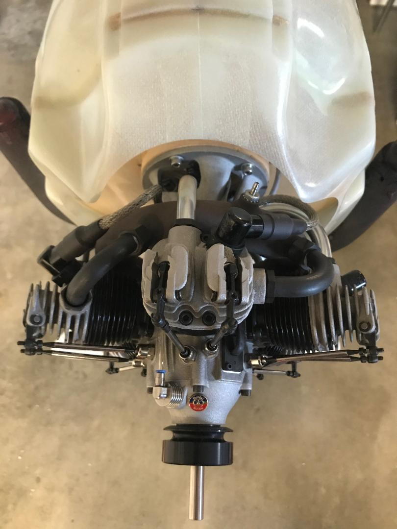
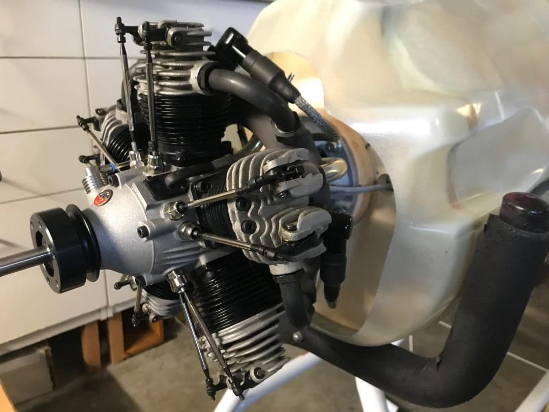
I have the old black top hat ignition on my Moki 250. As an option to upgrading to the new blue Moki or the rainbow-tronic, I was considering sending the engine to Ray English to install a CH Ignition that also replaces the internal coils with external ones.
I'd like to see if anyone has taken this route and what the results were? I have never dealt with Ray, so all I know is from a friend and the few things available online. I would like to hear other's experience with Ray, either with a Moki or other engines that Ray has worked on for you.
Thanks
I'd like to see if anyone has taken this route and what the results were? I have never dealt with Ray, so all I know is from a friend and the few things available online. I would like to hear other's experience with Ray, either with a Moki or other engines that Ray has worked on for you.
Thanks
12-19-2020, 01:02 AM
#4539
My Feedback: (360)
I have a 250 that is running on CH now. The spark is noticeably stronger. Engine runs like a sewing machine.
CH ignitions have quite a good reputation and have been around for years. The unit also has a tach output wire that you could take advantage of if your radio has telemetry.
I think the 150/180 series benefits the most from the upgrade, although I would not hesitate to change out any of the top hat style for the CH.
Keep in mind the US importer does not recommend the CH, but then again he sells a different brand, so you can make your own conclusions there
No personal experience with Ray, so can't comment there.
- Mike O.
12-19-2020, 05:18 AM
#4540
I have a 250 that is running on CH now. The spark is noticeably stronger. Engine runs like a sewing machine.
CH ignitions have quite a good reputation and have been around for years. The unit also has a tach output wire that you could take advantage of if your radio has telemetry.
I think the 150/180 series benefits the most from the upgrade, although I would not hesitate to change out any of the top hat style for the CH.
Keep in mind the US importer does not recommend the CH, but then again he sells a different brand, so you can make your own conclusions there
No personal experience with Ray, so can't comment there.
- Mike O.
CH ignitions have quite a good reputation and have been around for years. The unit also has a tach output wire that you could take advantage of if your radio has telemetry.
I think the 150/180 series benefits the most from the upgrade, although I would not hesitate to change out any of the top hat style for the CH.
Keep in mind the US importer does not recommend the CH, but then again he sells a different brand, so you can make your own conclusions there
No personal experience with Ray, so can't comment there.
- Mike O.
Must be reputable.
12-27-2020, 07:53 PM
#4541
My Feedback: (116)
Join Date: Aug 2004
Location: malibu,
CA
Posts: 29
Likes: 0
Received 0 Likes
on
0 Posts
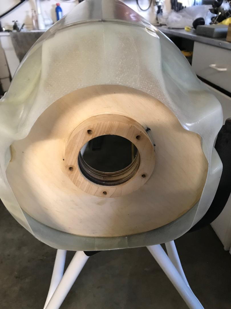
I'm working on a Comp-ARF pitts with a MOKI 250. This installation requires 1-1/2" standoffs. I was wondering if it is OK to use regular standoffs used in DA-170 or other large 2 strokes, on the MOKI factory mount. Moki comes with only 3 bolt holes on the mount, and was concerned about the torque on these standoffs. I have read through other build threads and see some that have used standoffs and some that built up a solid round mount with (6) 1/4" plywood pieces glued together to get the desired extension that supports the entire MOKI mount. I'm concerned about adding more weight in a location that I need to keep light, in order to balance.
Anyone know of an off the shelf, strong rigid standoff for he MOKI?
Anyone know of an off the shelf, strong rigid standoff for he MOKI?
12-28-2020, 05:51 AM
#4542
I'm working on a Comp-ARF pitts with a MOKI 250. This installation requires 1-1/2" standoffs. I was wondering if it is OK to use regular standoffs used in DA-170 or other large 2 strokes, on the MOKI factory mount. Moki comes with only 3 bolt holes on the mount, and was concerned about the torque on these standoffs. I have read through other build threads and see some that have used standoffs and some that built up a solid round mount with (6) 1/4" plywood pieces glued together to get the desired extension that supports the entire MOKI mount. I'm concerned about adding more weight in a location that I need to keep light, in order to balance.
Anyone know of an off the shelf, strong rigid standoff for he MOKI?
Anyone know of an off the shelf, strong rigid standoff for he MOKI?
I made a mounting ring from plywood. Really not that difficult.
Cut the rings from hard ply - use a jig saw.
Epoxy and clamp together.
Drill mounting holes.
Sand to final shape.
The following users liked this post:
Ryan NYP (01-04-2021)
12-28-2020, 07:46 AM
#4543
My Feedback: (116)
Join Date: Aug 2004
Location: malibu,
CA
Posts: 29
Likes: 0
Received 0 Likes
on
0 Posts
Thank you Richard. I'm also leaning towards this approach. My standard Moki mount has three bolt holes. Did you drill out two more holes in your mount? What thickness ply did you use? I need 1-1/2" standoffs, so at 1/4" ply thickness, I would need 6 pieces.
Has anyone successfully used any other off-the-shelf standoffs for Moki engines?
Has anyone successfully used any other off-the-shelf standoffs for Moki engines?
12-28-2020, 08:05 AM
#4544
Thank you Richard. I'm also leaning towards this approach. My standard Moki mount has three bolt holes. Did you drill out two more holes in your mount? What thickness ply did you use? I need 1-1/2" standoffs, so at 1/4" ply thickness, I would need 6 pieces.
Has anyone successfully used any other off-the-shelf standoffs for Moki engines?
Has anyone successfully used any other off-the-shelf standoffs for Moki engines?
As it is, the Moki mount footprint is, in my opinion, grossly UNDER-sized. I don't understand why Moki would keep the small mount footprint and REDUCE the number of mounting holes in a larger and much power powerful engine?
I used standard construction plywood and made sure the pieces did not have voids. Probably best to use the best qualify ply you can find.
I think what I used was half inch... I epoxied several layers together.
It is solid as a rock.
12-28-2020, 09:51 AM
#4545
My Feedback: (1)
People are failing to understand the actual mechanical loading. Instead, are overbuilding and adding needless mass. Nothing wrong with standoffs, usually only four, as we see used over and over on engines with significantly(!) more rotational vibration (boxer engines) generated during the combustion process.
The OEM engine mounting flange is way(!) more than adequate! Typical flanged standoffs that distribute loading, especially torsional, will function just fine. Plywood compresses / collapses, even more so when inadequate sized washers are not employed to distribute the (compressive) load over a significant area.
The OEM engine mounting flange is way(!) more than adequate! Typical flanged standoffs that distribute loading, especially torsional, will function just fine. Plywood compresses / collapses, even more so when inadequate sized washers are not employed to distribute the (compressive) load over a significant area.
12-28-2020, 10:46 AM
#4546
Others are failing to understand the torque generated by a Moki 250 spinning a 32x18, when compared to, say, a 150cc spinning a 30x12. The Moki will create TWICE the torsional twist. Further, hanging a 12 pound Moki on the end of a 16 sq. in. footprint represents significantly greater moment arm than an 8 pound 150 twin suspended from those same 16 square inches.
The even distribution of 5 bolts securing the engine mounting ring does not compress a ply mount, and the weight penalty, when compared to stand-offs, is insignificant.
That’s my $0.02.
Others can do what they want.
The even distribution of 5 bolts securing the engine mounting ring does not compress a ply mount, and the weight penalty, when compared to stand-offs, is insignificant.
That’s my $0.02.
Others can do what they want.
12-28-2020, 06:30 PM
#4547
My Feedback: (116)
Join Date: Aug 2004
Location: malibu,
CA
Posts: 29
Likes: 0
Received 0 Likes
on
0 Posts
A great conversation for sure. It would be great to hear from those who have used regular stand offs to share their experience. In the two build threads I've seen on the Comp-Arf Pitts, one used regular standoffs and the other built up his own plywood rings and sheeted it with carbon fiber and resin. He also used a solid carbon fiber ring, that the Moki mounted to. These builds were from a few years ago, so we do not know the long term outcome.
01-02-2021, 02:22 PM
#4548
[QUOTE=Lletisso;12649133]Hello, today I mesured my Moki 300, with a SEP 34/18, 3950rpm pulled 29,92kg. The proportion is equal as mesured Robert H with his Moki 180, I think with yours Moki 250 it sould be +- 25kg.
Here is my video:
I found a decent trust calculator in Excell, I think it is quite good when i put in my measured static trust values, it is useful to estimate and compare which propeller pulls the best. and also to compare various engines, you just need prop size and the rev. that the engine could do at maximum.
"www.electricrcaircraftguy.com/2013/09/propeller-static-dynamic-thrust-equation.html"
01-02-2021, 04:43 PM
#4549
My Feedback: (116)
Join Date: Aug 2004
Location: malibu,
CA
Posts: 29
Likes: 0
Received 0 Likes
on
0 Posts
Thanks Robert. Is my assumption correct that your SEP 34x18 is a 2-blade? I did not see the link to your video. I would be interested to see it. My Pitts will probably come in at about 24kg +/-, so right around 1 to 1 dry. Have you tried any composite props with better results? In my experience with a lot of large 2-strolke engines, the composites considerably outperform the wood props.
01-03-2021, 06:43 AM
#4550
Hi,
No my prop for the Moki 180 is a 2 blade Fiala 28 x 16. I have not yet tried a glass fiber on my moki, but for other engines i feel that the glasfiber propellers are more effective, maybe does not straighten out under load
I will soon get an Ramoser varioprop, by that i can set the best rpm/thrust, and its the most economic alternative than just buy a lot of fixed 3 bladers and try out.
My link is to a place where you can download an excel file to calculate a expected thrust for a certain propeller.
My P47 1/5 for the 180 is 18 kg and flies quite well, not super powerfull but ok.
"www.electricrcaircraftguy.com/2013/09/propeller-static-dynamic-thrust-equation.html"
Last edited by Robert-H; 01-03-2021 at 08:50 AM.