


S.S. PUMA: Combat Transport
 08-01-2007, 11:34 PM
#1
Senior Member
Thread Starter

Join Date: Apr 2004
Location: Los Altos,
CA
Posts: 314
Likes: 0
Received 0 Likes
on
0 Posts
Well I got bored of reading topics and posts here about NON-combat ships, so I figured I would spice things up a little with a topic about some REAL combat ships. A few weeks ago I started construction on a set of four small combat transports for the Western Warship Combat Club. They are scratch-built from aircraft plywood, and will hopefully be ready before the end of this combat season.
Basic Information
Name: PUMA
Class: Three-Island Tramp
Length: 24"
Beam: 4"
Machinery: 1 prop, 1 rudder
Speed: 25 knots
Armor: 1/16" balsa
Pump: The largest that can fit
Basic Information
Name: PUMA
Class: Three-Island Tramp
Length: 24"
Beam: 4"
Machinery: 1 prop, 1 rudder
Speed: 25 knots
Armor: 1/16" balsa
Pump: The largest that can fit
 08-01-2007, 11:49 PM
#2
Senior Member
Thread Starter
Join Date: Apr 2004
Location: Los Altos,
CA
Posts: 314
Likes: 0
Received 0 Likes
on
0 Posts
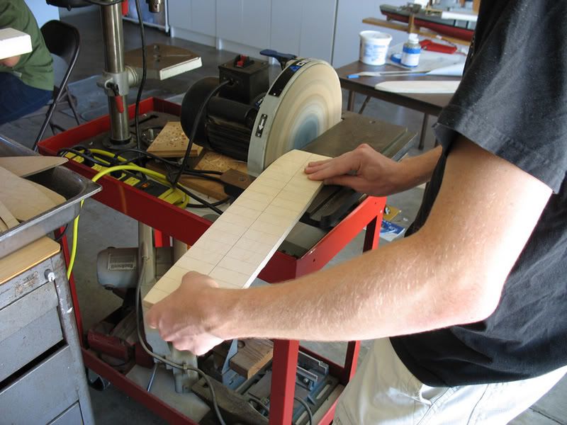
Construction began on July 21st, 2007 at precisely 12:42 PM, with the cutting of the sub-deck. The sub-deck is a major structural component in a scratch-built combat ship, because it provides the shape of the hull and a lot of the overall strength of the hull. I began by tracing the outline of the sub-deck onto the wood, then rough-cut it with a bandsaw. I then trimmed it to the trace with a large-diameter disk sander. Once the sub-deck for each ship was cut out, I separated the bow and stern islands from the amidships portion, then cut the insides out. I wanted the sub-deck to be very sturdy with lots of room to mount switches and stuff, so I made it 3/4" wide. I then checked my cuts to the plans, and called it a night.
Here's me sanding a sub-deck:
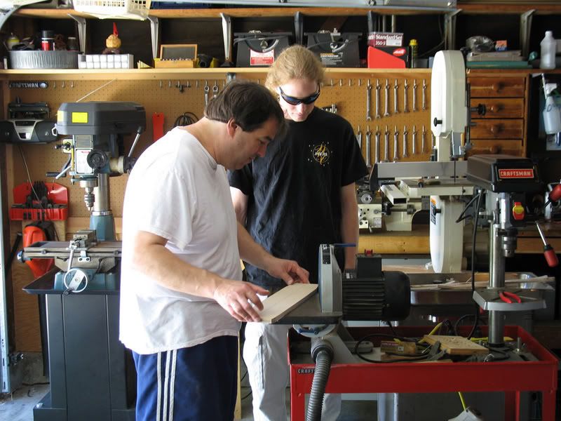
The shop-master testing the sander after replacing the sandpaper, using one of my sub-decks as the test piece:
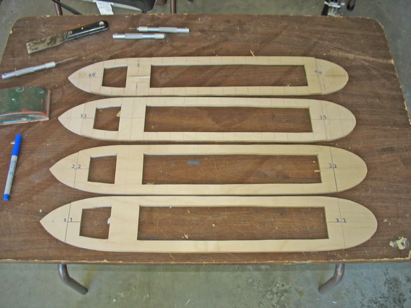
Four beautiful sub-decks:
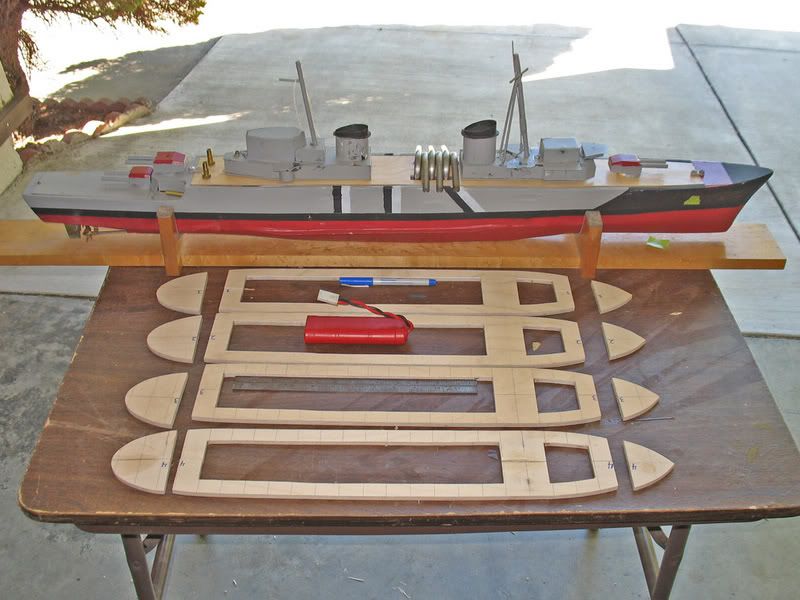
For size comparison, next to my german light cruiser:
Here's me sanding a sub-deck:
The shop-master testing the sander after replacing the sandpaper, using one of my sub-decks as the test piece:
Four beautiful sub-decks:
For size comparison, next to my german light cruiser:
08-02-2007, 12:08 AM
#3
Senior Member
Thread Starter
Join Date: Apr 2004
Location: Los Altos,
CA
Posts: 314
Likes: 0
Received 0 Likes
on
0 Posts
Construction continued on the 25th, with rib cutting. After cutting the first rib, I discovered that all of the rib patterns were not the right size. So I re-checked and re-drew every rib to match the plans and what I'd already made. That took the rest of the day, so no pictures from the 25th. On to the 28th, I cut out the ribs. Cutting out the ribs was very similar to cutting the subdeck. Trace the pattern, rough-cut, then sand to final shape. Double-check against plans and parts, and make any necessary adjustments. The ribs were made from 3/8" aircraft plywood, mostly dug up in the scrap bin. Someone else is building a pair of battleships in the shop, so scrap aircraft plywood in sufficient quantity and size is readily available at no cost to myself. Even the sub-decks were cut from scrap, so total expense right now is zero. I also cut out the bow keel for each ship. I am making two separate keels (bow and stern) for the transports, to save internal space. A full-length keel pushes up heavy objects like batteries and motors, and a ship this size needs everything as low as it can go. A full-length keel also interferes with the installation of a water-channel for damage control, while two separate keels actually makes the task easier.
Over half way done with the ribs! YAY!
Finished with the ribs and bow keel:
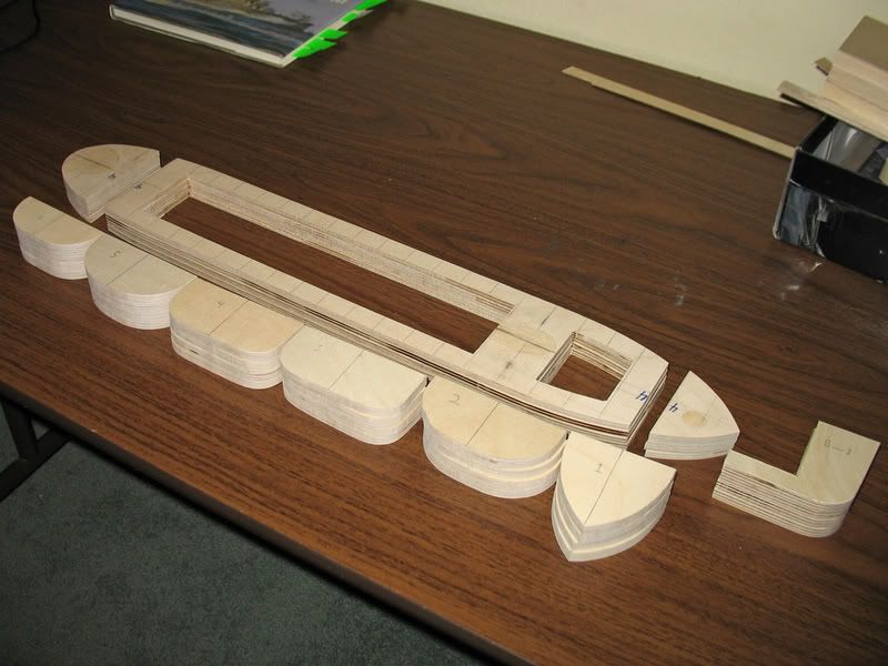
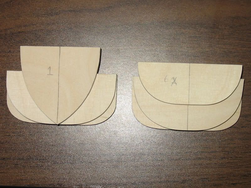
One complete set of ribs. Fine lines, huh?
My next build day is Saturday, August 4. The objective is to build the stern keels and install the stuffing tubes. Watch out because I have something very cool planned.
Over half way done with the ribs! YAY!
Finished with the ribs and bow keel:
One complete set of ribs. Fine lines, huh?
My next build day is Saturday, August 4. The objective is to build the stern keels and install the stuffing tubes. Watch out because I have something very cool planned.
08-05-2007, 02:37 PM
#6
Senior Member
Thread Starter
Join Date: Apr 2004
Location: Los Altos,
CA
Posts: 314
Likes: 0
Received 0 Likes
on
0 Posts
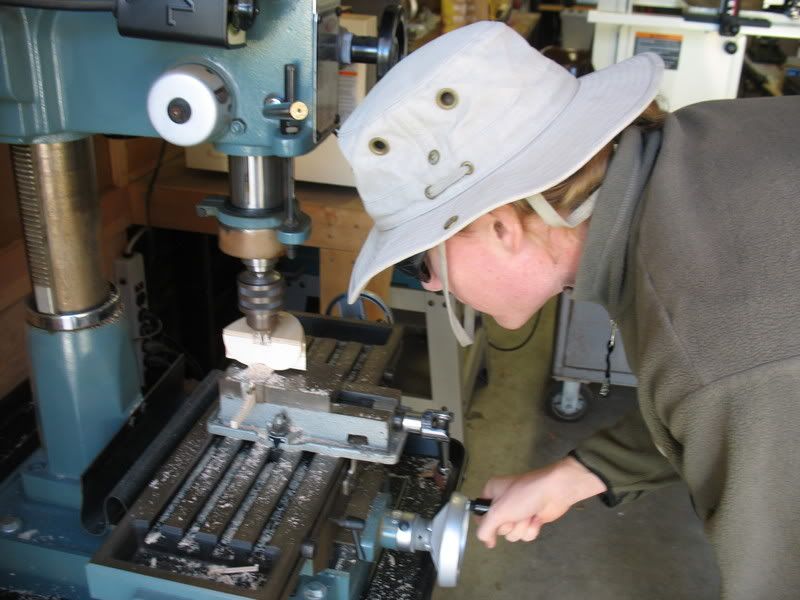
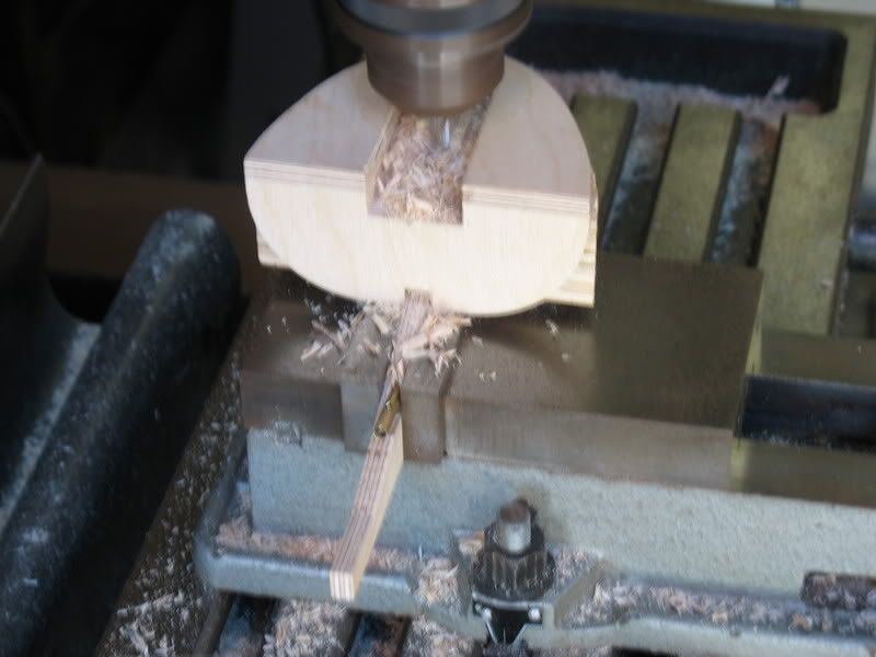
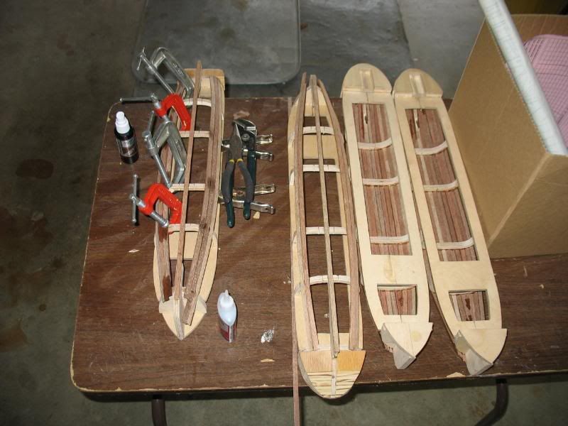
All right boys and girls, I made some good progress yesterday. The task of the day was to build the stern keel for each ship. This presented an interesting challenge, because I also had to get the stuffing tube installed through the keel. I have seen plenty of people turn the keel on end and try to drill a hole, but every time its been a disaster. I had to do something different. I partially cut out the keels, then one by one stuck them in a milling machine and cut a slot for the stuffing tube. The result was great: the keels are still sturdy, the stuffing tubes will go in straight and smooth, and with the keels done I am finally able to start test-fitting various components. And now, without further ado, the photos!
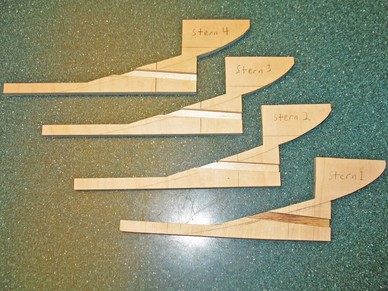
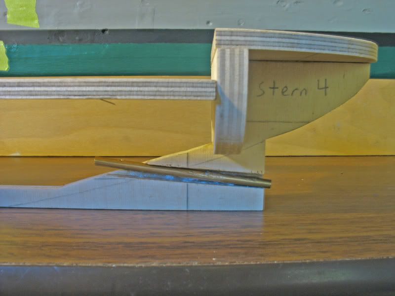
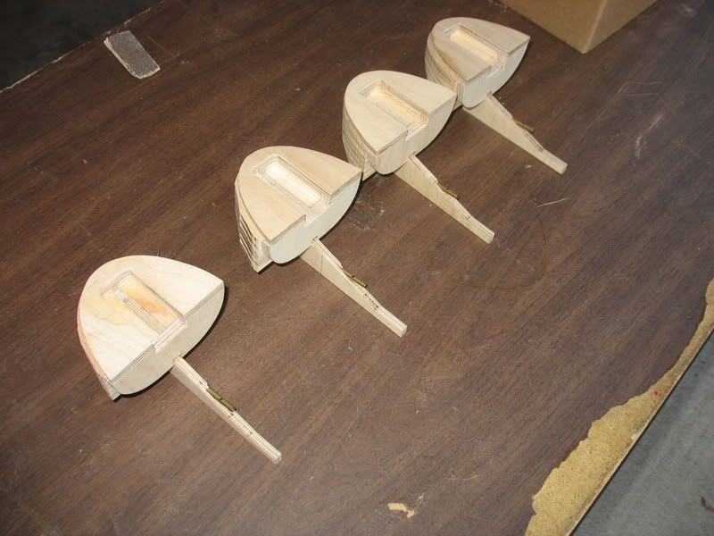
The keels! Note the slot cut for the stuffing tube, slightly angled to better fit the motor later on.
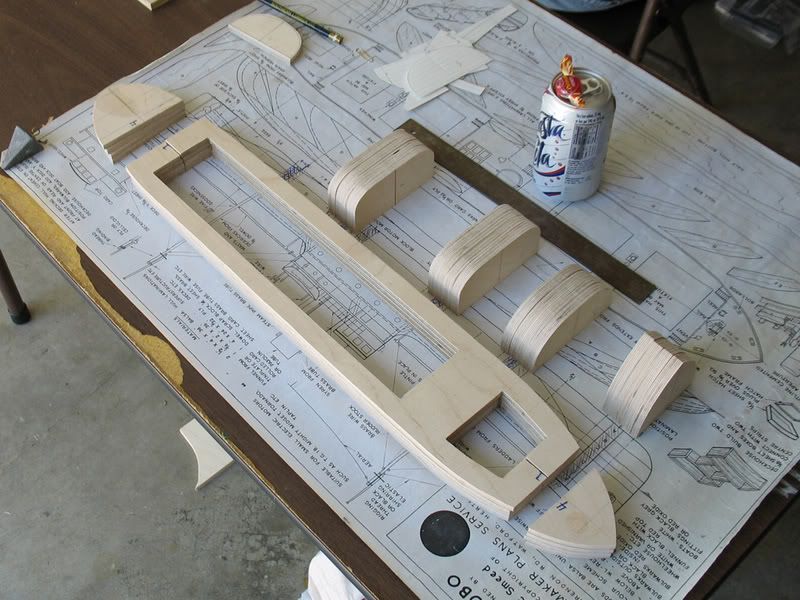
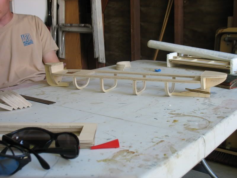
Here is a basic test assembly. I have not notched ribs 1, 5, or 6, so those have not been included. This shows the basic size and layout of the ship, especially the islands at the bow and stern.
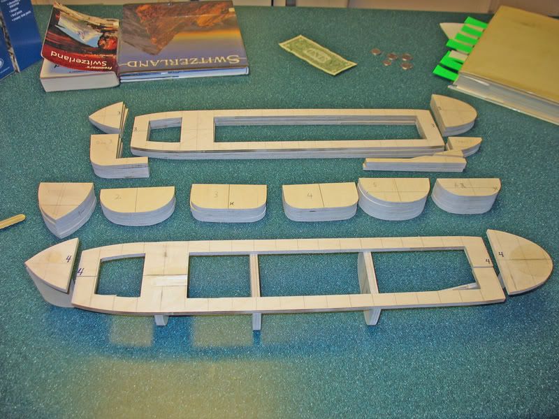
And here are a few components I may be using. Of special note is the pump. The WWCC restricts transports to one pump, 1/4" outlet, no maximum GPH. The pump shown is a standard pump used in most battleships, capable of surviving 5-6 large holes below the belt or at least one large rip. If the transports' agility can't save them, then the bilge pump will (for at least a few shots). And since the superstructure will be hollow, its OK that the pump sticks up above deck level.
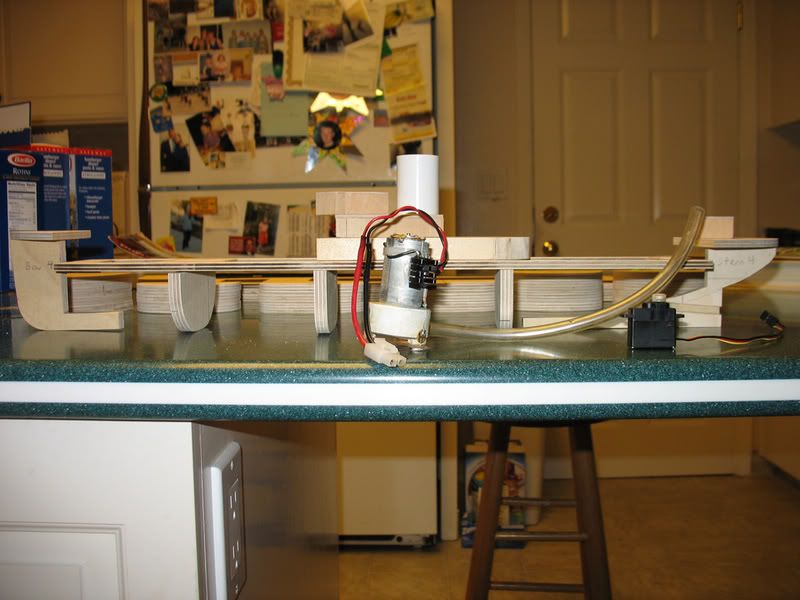
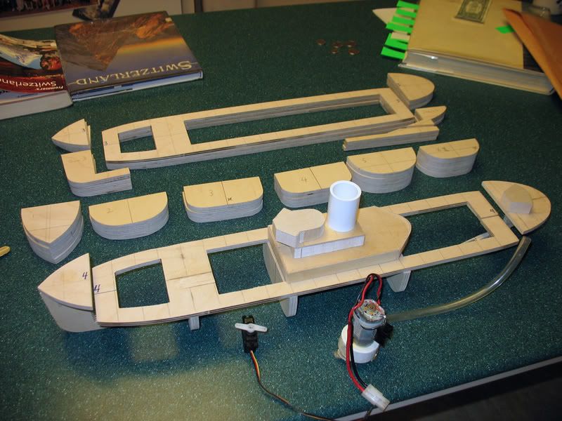
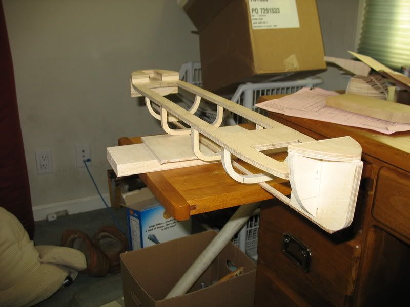
And now a test assembly, borrowing the superstructure from my brother's cruiser. This is just to give an overall idea what the ship will look like in the end. The center island is 3 layers of 1/2" balsa plated with 1/16" ply, as is the aft deckhouse. The structures from my brother's cruiser are not the right shape for the PUMA, but they demonstrate how I will construct the superstructure.
The keels! Note the slot cut for the stuffing tube, slightly angled to better fit the motor later on.
Here is a basic test assembly. I have not notched ribs 1, 5, or 6, so those have not been included. This shows the basic size and layout of the ship, especially the islands at the bow and stern.
And here are a few components I may be using. Of special note is the pump. The WWCC restricts transports to one pump, 1/4" outlet, no maximum GPH. The pump shown is a standard pump used in most battleships, capable of surviving 5-6 large holes below the belt or at least one large rip. If the transports' agility can't save them, then the bilge pump will (for at least a few shots). And since the superstructure will be hollow, its OK that the pump sticks up above deck level.
And now a test assembly, borrowing the superstructure from my brother's cruiser. This is just to give an overall idea what the ship will look like in the end. The center island is 3 layers of 1/2" balsa plated with 1/16" ply, as is the aft deckhouse. The structures from my brother's cruiser are not the right shape for the PUMA, but they demonstrate how I will construct the superstructure.
09-10-2007, 12:22 AM
#7
Senior Member
Thread Starter
Join Date: Apr 2004
Location: Los Altos,
CA
Posts: 314
Likes: 0
Received 0 Likes
on
0 Posts
Just so you guys know, I have not forgotten about this thread and I have not stopped the construction. The ships are further along now, and I plan to assemble the ribs, keels, and subdecks into a recognizable boat-shape next saturday. I hope to post pics of the process as well. After that it's a whole lotta planking, then guts and superstructure.


 01-15-2008, 10:00 PM
#11
Senior Member
Thread Starter
Join Date: Apr 2004
Location: Los Altos,
CA
Posts: 314
Likes: 0
Received 0 Likes
on
0 Posts
Just so you know, I haven't forgotten about this thread. I just kind of... yeah, I forgot. But I HAVE been building the boats, and taking photos. So take a look at all my wonderful progress!
Installing the propshaft. At this point the shaft is glued in, but it has not been filled or sanded.
Cutting a space for the steering stuff after assembling the aft keel parts. Please note I'm using a mill to cut the slot, for a nicer overall finish and super-thick sturdy impenetrable areas.
A closer look at the slot I cut for the steering stuff. Not exactly CNC-router quality, but better than anything else I've seen.
The final product:
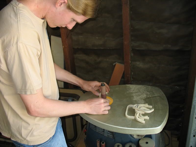
Cutting out the insides of the ribs. I did a rough cut with the bandsaw, then cleaned everything up with a spindle sander. Very handy to have around.
A quick test assembly. Yep, everything still looks good.
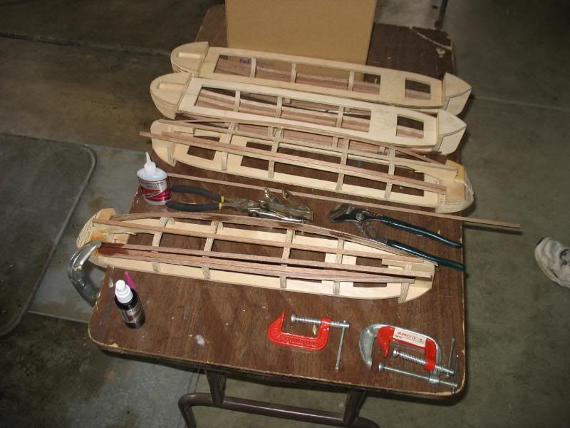
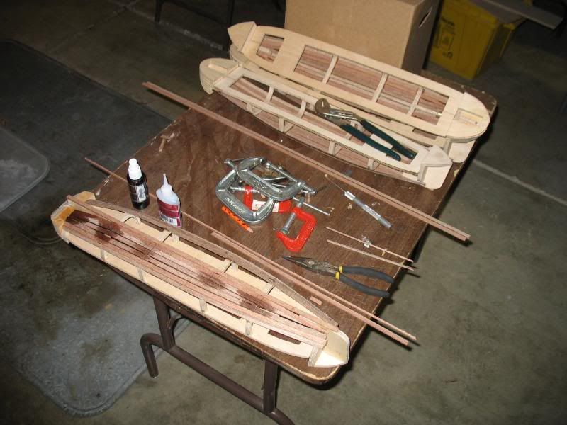
Final assembly, including keel plank. This will be one fine little boat when it's done.
An underside view shows off the keel plank very well.

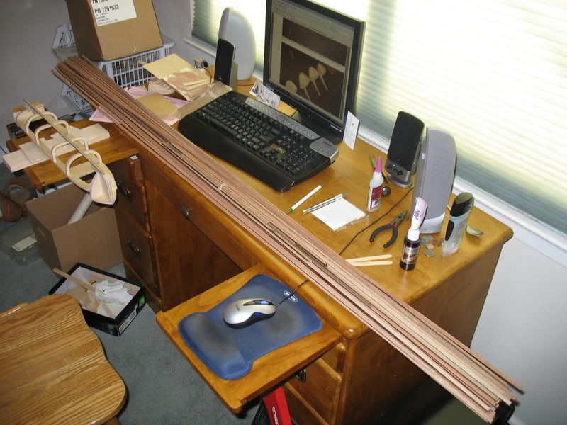
The planks for use on the impenetrable underbelly of each ship. That's a big bundle of planks!
Almost done! Just working on the last planks for the last boat.
The planks I used were a little stiffer than expected. I had to clamp them down while the glue hardened. That slowed me down a little bit but not too much.
Drying accelerant fades on the now-complete port side of transport hull #4.
I did complete the planking shortly afterwards, but my camera ran out of batteries before I could take any more photos. The latest news is that hull #3 has started to warp. It's been a little over a week since everything was completed and all the other hulls are fine, but hull #3 has started warping so badly that the ribs are popping off and in some places there is more than 1/8" between the high and low sections. To repair the damage, I purchased two plates of 4"x1/2" aluminum. I plan to clamp the warped hull firmly down to one of the aluminum plates to force everything flat, then I'll epoxy the #@$% out of it. I also plan to reinforce the rib joints with thin metal pins, and the second plate is to help flatten the top of the ship. Once the warping is repaired, I'll epoxy the other hulls to seal them against water, then install water channeling.
It'll be a little while until my next post, because school just resumed. Winter break was sooo short...
Installing the propshaft. At this point the shaft is glued in, but it has not been filled or sanded.
Cutting a space for the steering stuff after assembling the aft keel parts. Please note I'm using a mill to cut the slot, for a nicer overall finish and super-thick sturdy impenetrable areas.
A closer look at the slot I cut for the steering stuff. Not exactly CNC-router quality, but better than anything else I've seen.
The final product:
Cutting out the insides of the ribs. I did a rough cut with the bandsaw, then cleaned everything up with a spindle sander. Very handy to have around.
A quick test assembly. Yep, everything still looks good.
Final assembly, including keel plank. This will be one fine little boat when it's done.
An underside view shows off the keel plank very well.
The planks for use on the impenetrable underbelly of each ship. That's a big bundle of planks!
Almost done! Just working on the last planks for the last boat.
The planks I used were a little stiffer than expected. I had to clamp them down while the glue hardened. That slowed me down a little bit but not too much.
Drying accelerant fades on the now-complete port side of transport hull #4.
I did complete the planking shortly afterwards, but my camera ran out of batteries before I could take any more photos. The latest news is that hull #3 has started to warp. It's been a little over a week since everything was completed and all the other hulls are fine, but hull #3 has started warping so badly that the ribs are popping off and in some places there is more than 1/8" between the high and low sections. To repair the damage, I purchased two plates of 4"x1/2" aluminum. I plan to clamp the warped hull firmly down to one of the aluminum plates to force everything flat, then I'll epoxy the #@$% out of it. I also plan to reinforce the rib joints with thin metal pins, and the second plate is to help flatten the top of the ship. Once the warping is repaired, I'll epoxy the other hulls to seal them against water, then install water channeling.
It'll be a little while until my next post, because school just resumed. Winter break was sooo short...
02-05-2008, 10:18 PM
#12
Senior Member
Thread Starter
Join Date: Apr 2004
Location: Los Altos,
CA
Posts: 314
Likes: 0
Received 0 Likes
on
0 Posts
***UPDATE***
After assembling the hulls and planking them, I discovered that one of the hulls had begun to warp. This was a particularly severe warping, in that the hull went up and down at least two times, with up to 1/8" of flexing. Worse, the superglue joints were failing, and there was only one rib holding the frame together. I could not accept the loss of a hull, so I acted quickly to salvage the situation. I purchased two 4"wide by 1/2" thick plates of aluminum, and clamped the hull firmly down to one of the plates. Clamping the hull to the aluminum plate straightened the hull, and I applied a liberal layer of epoxy on the inside to make the correction permanent. After that I straightened out the rib joints and reinforced those with another liberal layer of epoxy. I then repeated the procedure for the other three hulls, to waterproof and strengthen the hulls before continuing construction.
Rusty old C-clamps hold the hull tight against the aluminum plate while the epoxy hardens
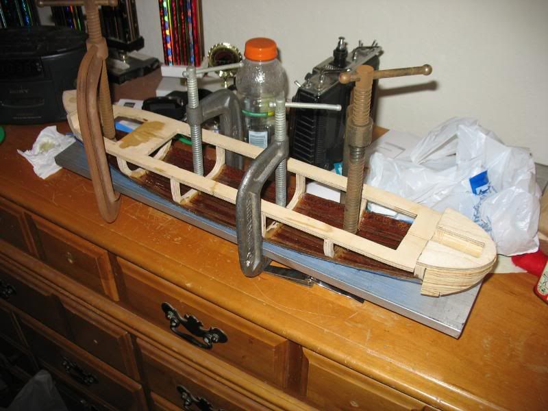
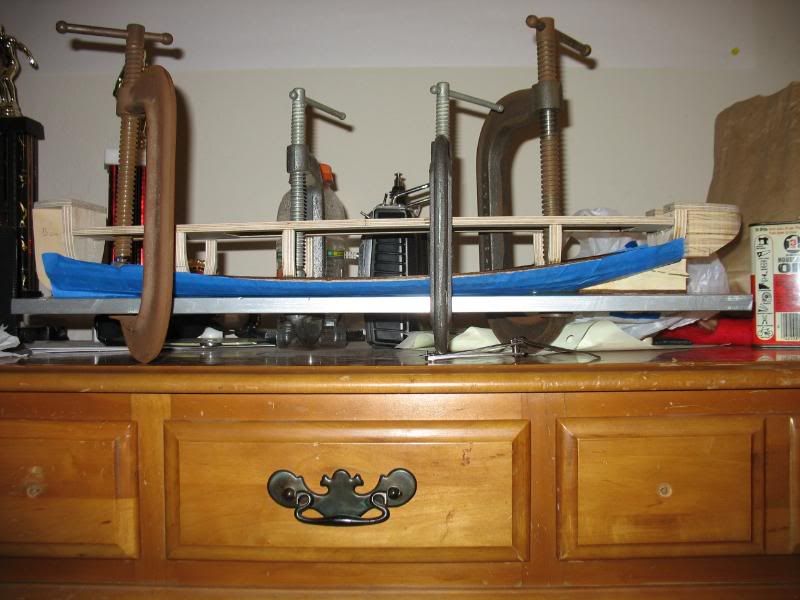
Now that's one flat-bottomed boat! No more warping here. The blue tape is to prevent epoxy from leaking out the bottom as it fills in the cracks in the planking.
After assembling the hulls and planking them, I discovered that one of the hulls had begun to warp. This was a particularly severe warping, in that the hull went up and down at least two times, with up to 1/8" of flexing. Worse, the superglue joints were failing, and there was only one rib holding the frame together. I could not accept the loss of a hull, so I acted quickly to salvage the situation. I purchased two 4"wide by 1/2" thick plates of aluminum, and clamped the hull firmly down to one of the plates. Clamping the hull to the aluminum plate straightened the hull, and I applied a liberal layer of epoxy on the inside to make the correction permanent. After that I straightened out the rib joints and reinforced those with another liberal layer of epoxy. I then repeated the procedure for the other three hulls, to waterproof and strengthen the hulls before continuing construction.
Rusty old C-clamps hold the hull tight against the aluminum plate while the epoxy hardens
Now that's one flat-bottomed boat! No more warping here. The blue tape is to prevent epoxy from leaking out the bottom as it fills in the cracks in the planking.
02-06-2008, 03:31 PM
#13
Senior Member
Thread Starter
Join Date: Apr 2004
Location: Los Altos,
CA
Posts: 314
Likes: 0
Received 0 Likes
on
0 Posts
MORE PROGRESS!!!
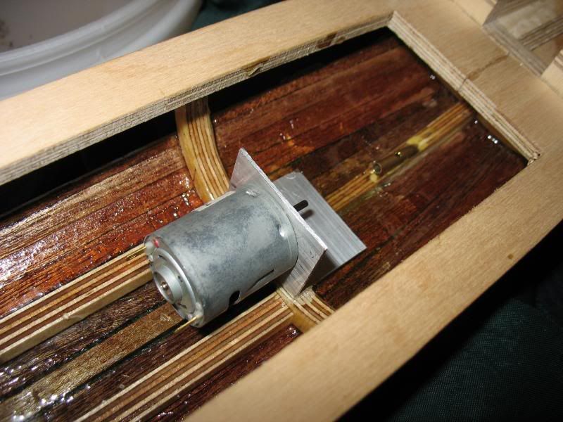
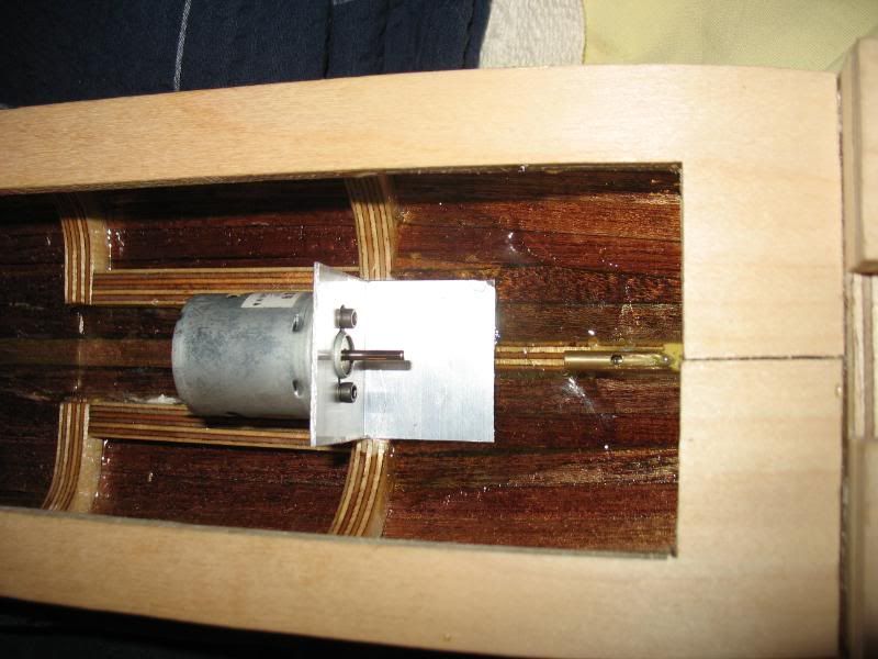
Actually, this is stuff I did last week, but only just now took pictures of it. Anyway, I built and installed the motor mounts, and began to install water channeling. The motor mounts were made from simple 90 degree angle aluminum. I drilled a hole for the front bushing on the motor to stick through, then cut a slot to either side for the screws. Alignment and positioning of the motor mounts are very good, and they are firmly held in place by a puddle of epoxy. The drive motor is a RS-365SH surplus motor. It's got very low power requirements (less than 2 amps STALL), low RPMs (about 8000-9000 free-spinning), and plenty of torque (I could not stop it with my fingers), so I'm going for a simple direct drive.
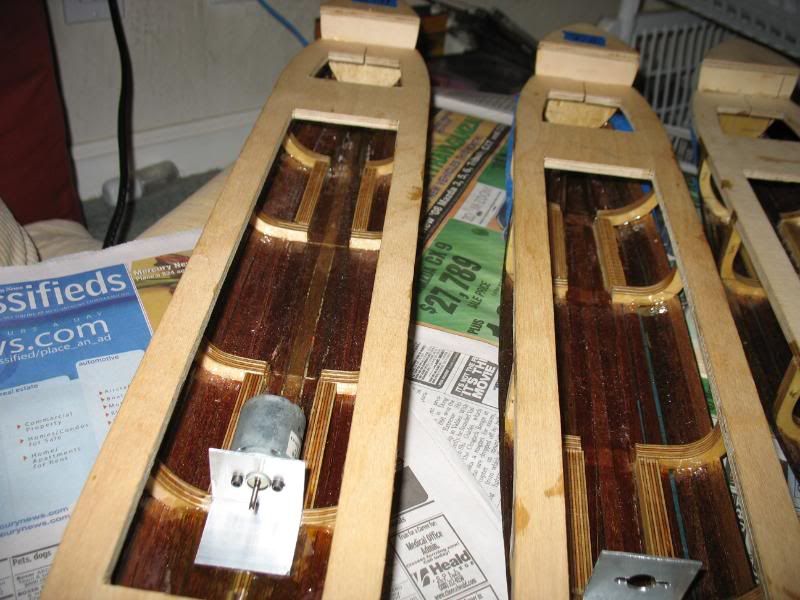
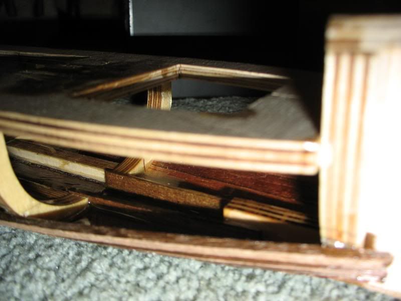
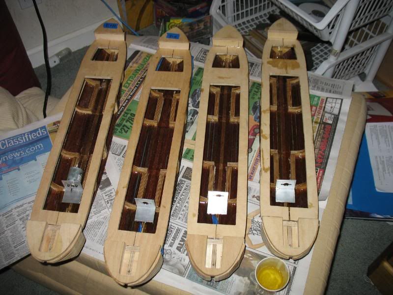
The water channeling is a little bit more challenging. The purpose of a water channel is to guide any water that enters the ship towards the pump, and prevent it from collecting in undesired areas and causing a list. To do that, you fill up all the undesired areas with some material, make the pump the lowest area in the ship (water always flows downhill), and make that downhill path as simple and unobstructed as possible. For these ships, the plan was to lay down two parallel barriers in the bottom of the boat, clear out the area between them, then fill the areas to either side with lead shot and epoxy. The lead shot would serve as ballast, and the thick layer of epoxy would raise the floor of the sides to higher than the floor of the water channel. So far I have installed most of the barriers. I will hold off on the lead and epoxy until I've done an initial ballast-test and I know how much lead I need to add to the epoxy mixture.
Anyway, enough with the verbage. Let's see some pictures!
The motor and its mount:
Another view of the motor and its mount:

This one shows off the puddle of epoxy that I poured to hold the mount in place:
Here's an overview of the water channeling that I have currently intalled. Note that the amidships section is currently clear, but it will get its barriers installed as soon as I buy bilge pumps for the ships.
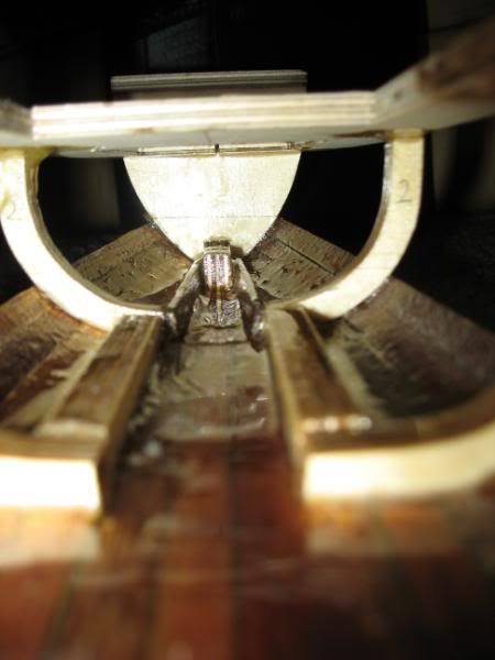
An interesting perspective on the water channeling in the bow:
Yes folks, there is water channeling in the furthest forward section of the ship. I just used short planks instead of plywood because of the extensive curvature of the hull that far forward.
And what would a major update like this be without showing the progress of all four boats?
Actually, this is stuff I did last week, but only just now took pictures of it. Anyway, I built and installed the motor mounts, and began to install water channeling. The motor mounts were made from simple 90 degree angle aluminum. I drilled a hole for the front bushing on the motor to stick through, then cut a slot to either side for the screws. Alignment and positioning of the motor mounts are very good, and they are firmly held in place by a puddle of epoxy. The drive motor is a RS-365SH surplus motor. It's got very low power requirements (less than 2 amps STALL), low RPMs (about 8000-9000 free-spinning), and plenty of torque (I could not stop it with my fingers), so I'm going for a simple direct drive.
The water channeling is a little bit more challenging. The purpose of a water channel is to guide any water that enters the ship towards the pump, and prevent it from collecting in undesired areas and causing a list. To do that, you fill up all the undesired areas with some material, make the pump the lowest area in the ship (water always flows downhill), and make that downhill path as simple and unobstructed as possible. For these ships, the plan was to lay down two parallel barriers in the bottom of the boat, clear out the area between them, then fill the areas to either side with lead shot and epoxy. The lead shot would serve as ballast, and the thick layer of epoxy would raise the floor of the sides to higher than the floor of the water channel. So far I have installed most of the barriers. I will hold off on the lead and epoxy until I've done an initial ballast-test and I know how much lead I need to add to the epoxy mixture.
Anyway, enough with the verbage. Let's see some pictures!
The motor and its mount:
Another view of the motor and its mount:
This one shows off the puddle of epoxy that I poured to hold the mount in place:
Here's an overview of the water channeling that I have currently intalled. Note that the amidships section is currently clear, but it will get its barriers installed as soon as I buy bilge pumps for the ships.
An interesting perspective on the water channeling in the bow:
Yes folks, there is water channeling in the furthest forward section of the ship. I just used short planks instead of plywood because of the extensive curvature of the hull that far forward.
And what would a major update like this be without showing the progress of all four boats?
