


8th Scale Aviation's, "CzechMate" Short-kit, Group build
 08-16-2020, 11:01 AM
#326

Thread Starter

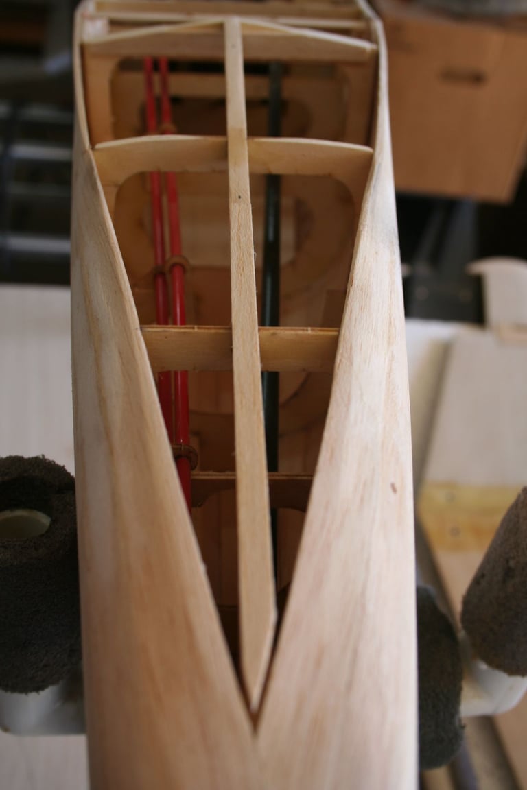
Our next step was to finish sheeting the fuse -- more specifically, sheeting the bottom:
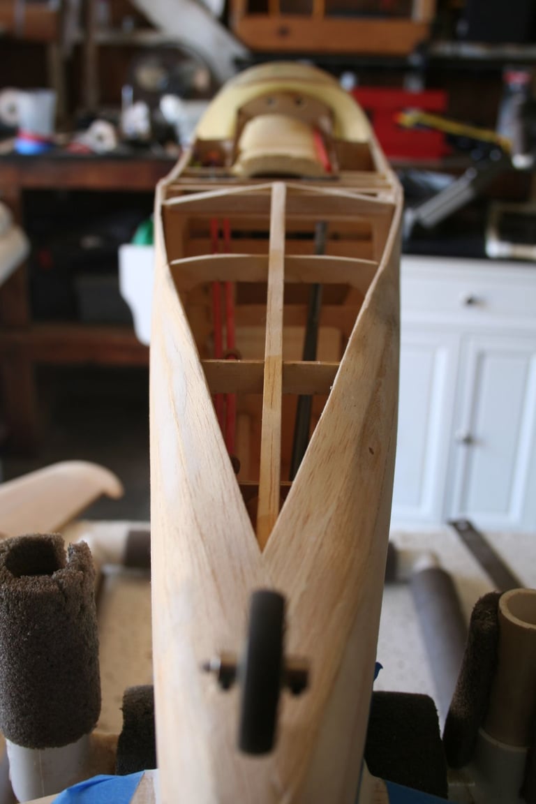
Just as a reminder, this is what it looks like, at this stage.
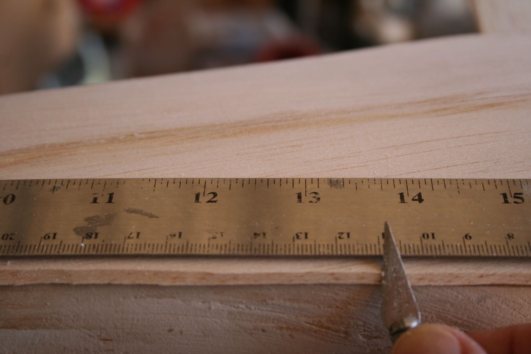
The first thing I did was to mark mid-points along the length of the exposed keel.
A ruler and extra-fine tip Sharpie were used for this task.
If you look closely, the mid-point marks are visible.
Because the bottom of the fuse is relatively straight, there is no further planking. Instead, the bottom will be sheeted with two solid pieces of 3/32" balsa sheet.
Place the edge of one sheet of 3/32" balsa at the midpoint so it extends beyond the side planking. Trace where the sheet intersects the outside of the planking. Repeat this step for the opposite side. Trim both sheets just outside of the traced lines.
Just as a reminder, this is what it looks like, at this stage.
The first thing I did was to mark mid-points along the length of the exposed keel.
A ruler and extra-fine tip Sharpie were used for this task.
If you look closely, the mid-point marks are visible.
Because the bottom of the fuse is relatively straight, there is no further planking. Instead, the bottom will be sheeted with two solid pieces of 3/32" balsa sheet.
Place the edge of one sheet of 3/32" balsa at the midpoint so it extends beyond the side planking. Trace where the sheet intersects the outside of the planking. Repeat this step for the opposite side. Trim both sheets just outside of the traced lines.
 08-16-2020, 11:14 AM
#327
Thread Starter
Several inches of a scrap piece of 1/8 x 1/4" balsa stick was fitted to the angle of the edges of the planking at the rear of the fuse, just ahead of the tailwheel. (This was used to raise the keel to the level of the planking so the 3/32" sheeting has appropriate structure to be glued to, and to keep the appropriate outer shape.). When satisfied with the fit, use medium CA to glue it to the keel.
08-16-2020, 11:32 AM
#328
Thread Starter
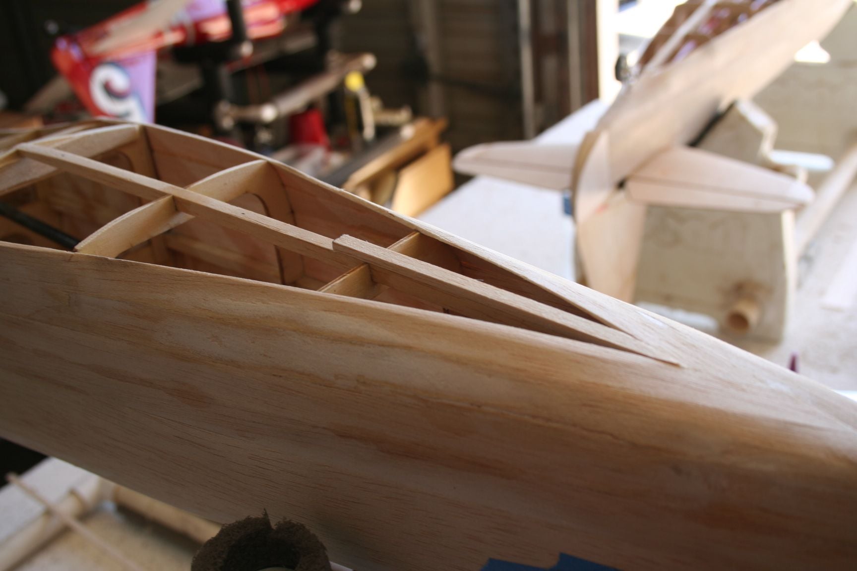
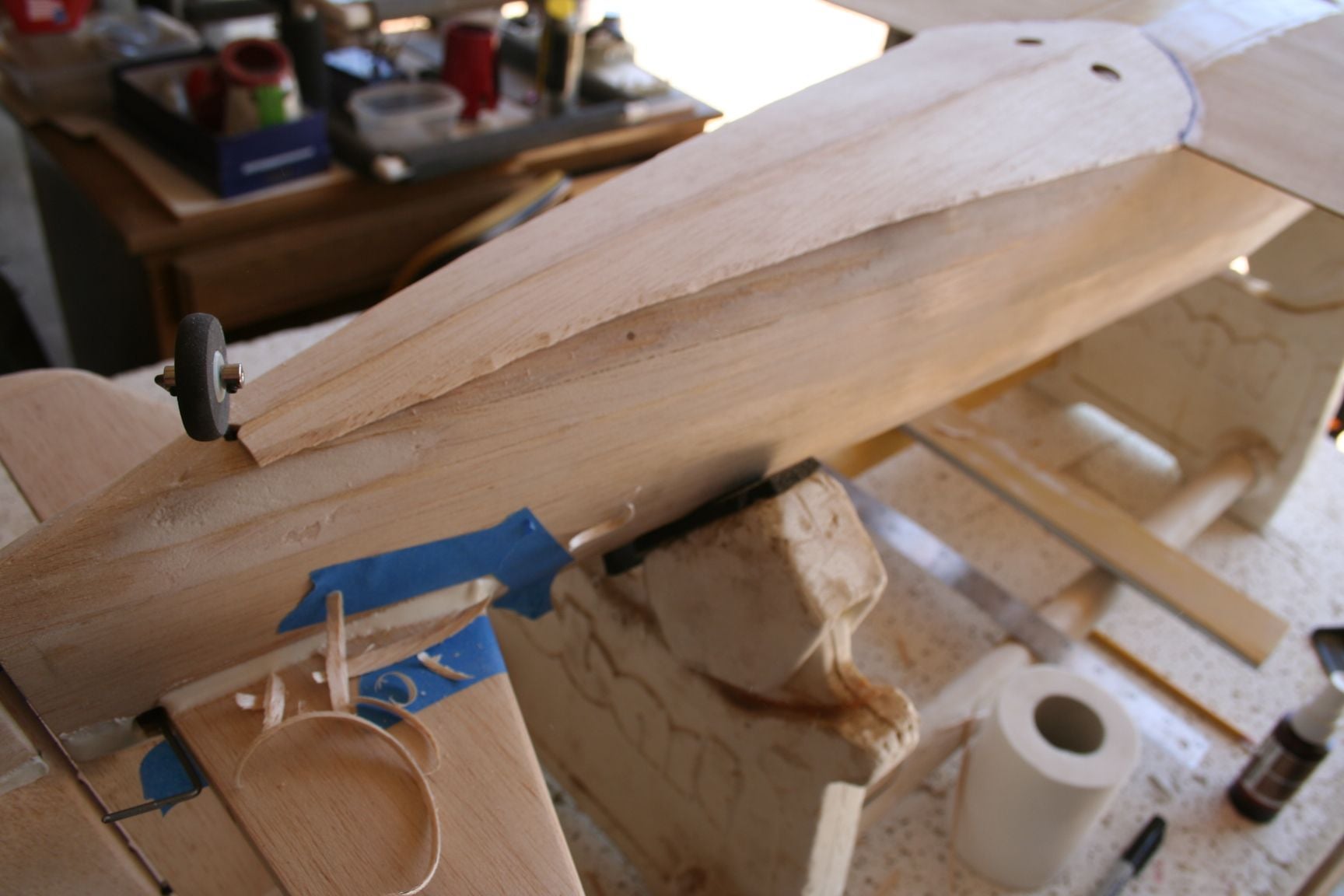
Being very careful to keep it level, and avoid taking much of the side planking down, I used a sanding bar to "rough-sand" the extended keel piece to the level of the sheeting.
A home-made narrow sanding block was used to smoothly transition (or blend) the extended keel to the level of original keel, further forward, and to avoid sanding the sheeting any further.
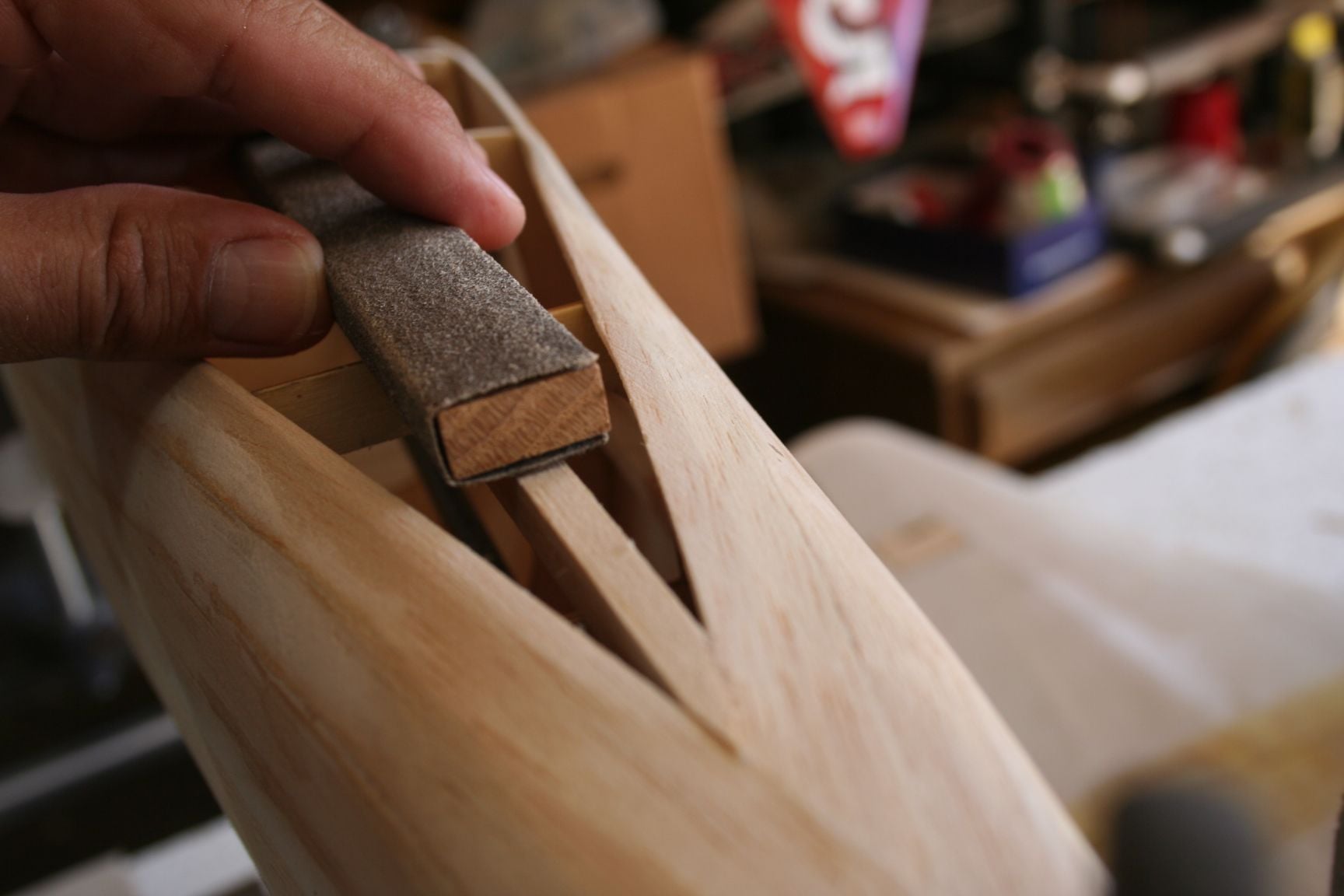
Beings my side planking did not completely conceal the corners of each the fuse formers, I also found it desirable to lightly sand the outer corners, beveling them slightly, in order to ensure the sheet would lie flat across all surfaces, upon gluing.
A home-made narrow sanding block was used to smoothly transition (or blend) the extended keel to the level of original keel, further forward, and to avoid sanding the sheeting any further.
Beings my side planking did not completely conceal the corners of each the fuse formers, I also found it desirable to lightly sand the outer corners, beveling them slightly, in order to ensure the sheet would lie flat across all surfaces, upon gluing.
08-16-2020, 11:48 AM
#329

My Feedback: (60)
Join Date: Dec 2001
Location: Litchfield Park,
AZ
Posts: 7,677
Likes: 0
Received 25 Likes
on
23 Posts
Speaking of which, brings me to Chad:
I just want to express again how grateful I am to you, for all the support and advice you have provided me (and so many others within the RCU community) over the years. I eagerly follow your builds, and have always been very impressed with the results. Your original CzechMates (built with your friend) were the very first version I ever saw modeled accurately. It was beautiful, and a joy to see take to the air. I look forward to seeing the progress of Perestroika, and its successful flights, as well.
I just want to express again how grateful I am to you, for all the support and advice you have provided me (and so many others within the RCU community) over the years. I eagerly follow your builds, and have always been very impressed with the results. Your original CzechMates (built with your friend) were the very first version I ever saw modeled accurately. It was beautiful, and a joy to see take to the air. I look forward to seeing the progress of Perestroika, and its successful flights, as well.
08-16-2020, 12:06 PM
#330
Thread Starter
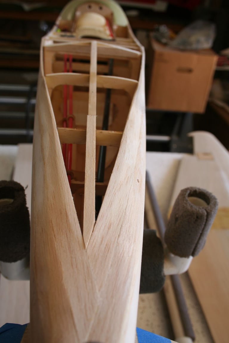
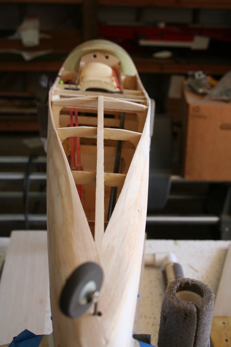
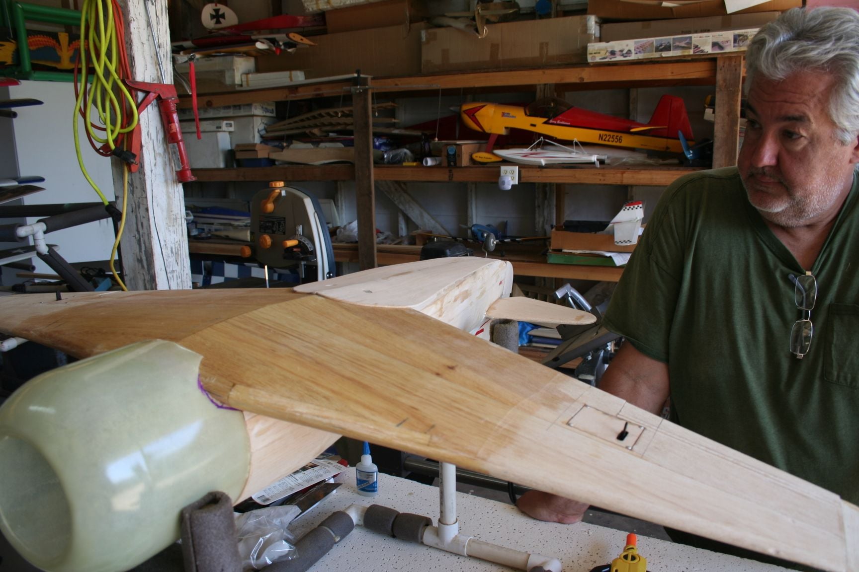
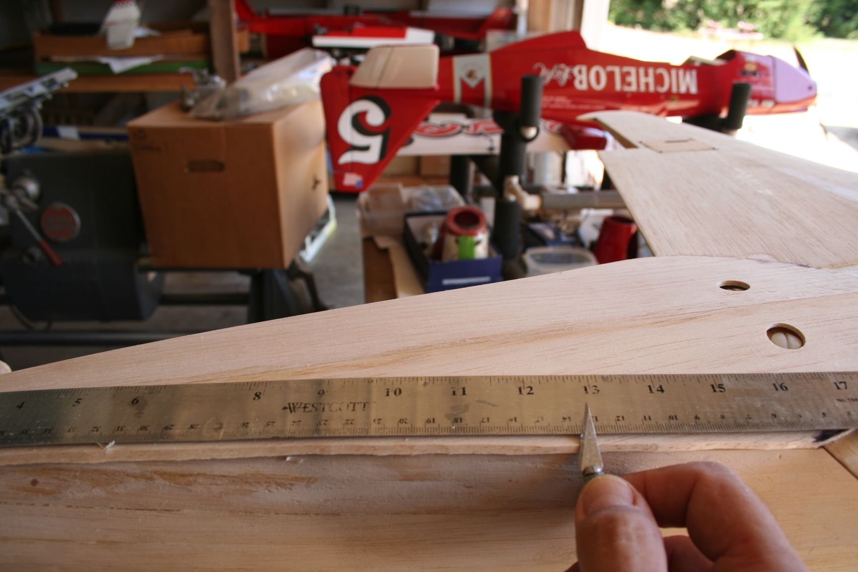
In the process of this necessary sanding, I sanded away the mid-points of the keel, and now need to re-measure and re-mark them (as is visible the picture below).
Re-mount the wing to the fuse.
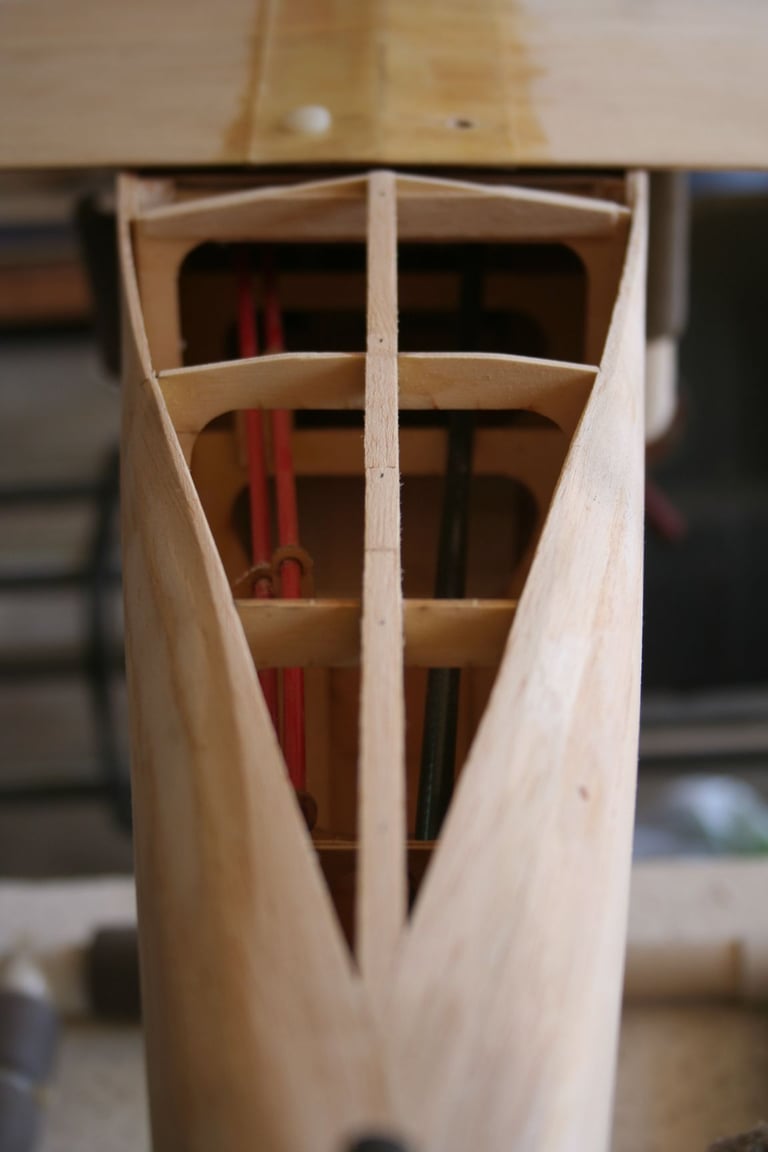
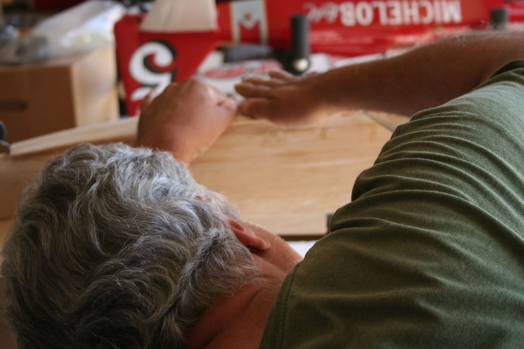
In the picture below, Tim now mounts and glues two pieces of scrap 3/32" sheet (right and left sides) on the trailing edge of my wing for me, and does the same on his CzechMate. We then sanded these pieces to a slightly flatter bevel than that of the fuse former just to the rear. The idea is to transition the bottom fuse sheeting from the sharper angle of the rear fuse when it eventually meets the flatter angle of the wing dihedral. (This will be more clear when you look ahead to additional pictures in the following posts.)

Re-mount the wing to the fuse.
In the picture below, Tim now mounts and glues two pieces of scrap 3/32" sheet (right and left sides) on the trailing edge of my wing for me, and does the same on his CzechMate. We then sanded these pieces to a slightly flatter bevel than that of the fuse former just to the rear. The idea is to transition the bottom fuse sheeting from the sharper angle of the rear fuse when it eventually meets the flatter angle of the wing dihedral. (This will be more clear when you look ahead to additional pictures in the following posts.)

 08-16-2020, 12:27 PM
#332
Thread Starter
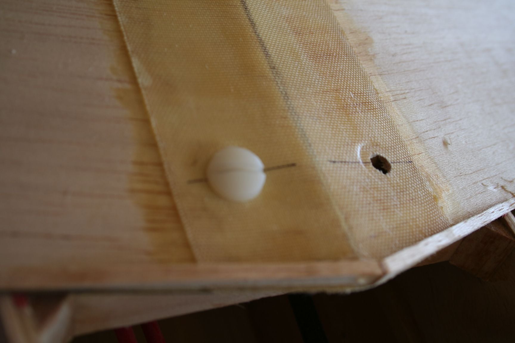
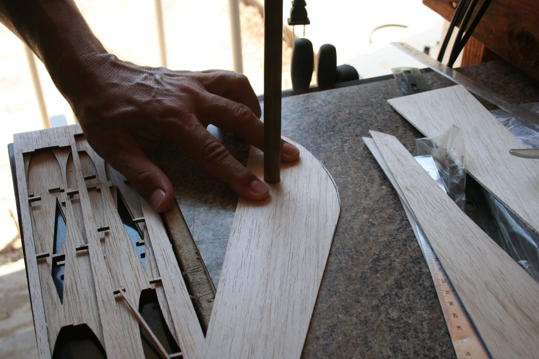
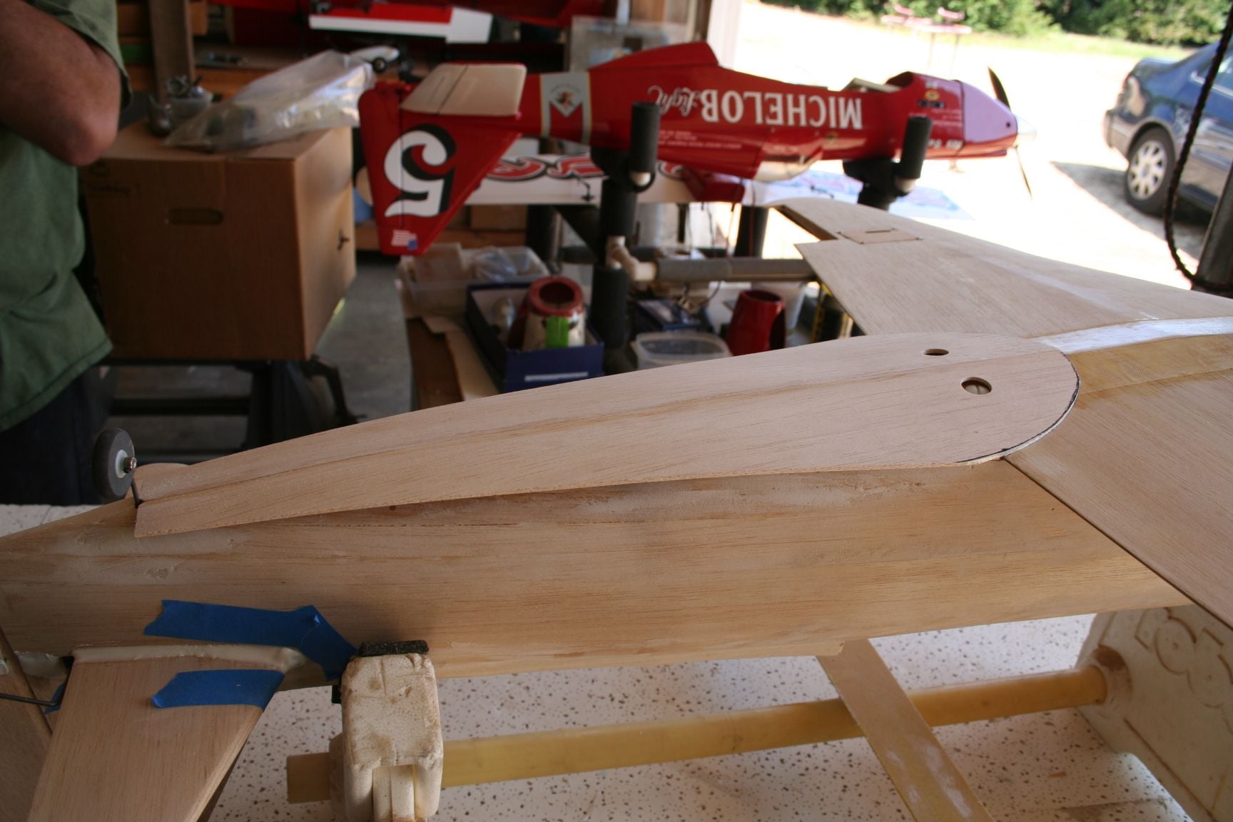
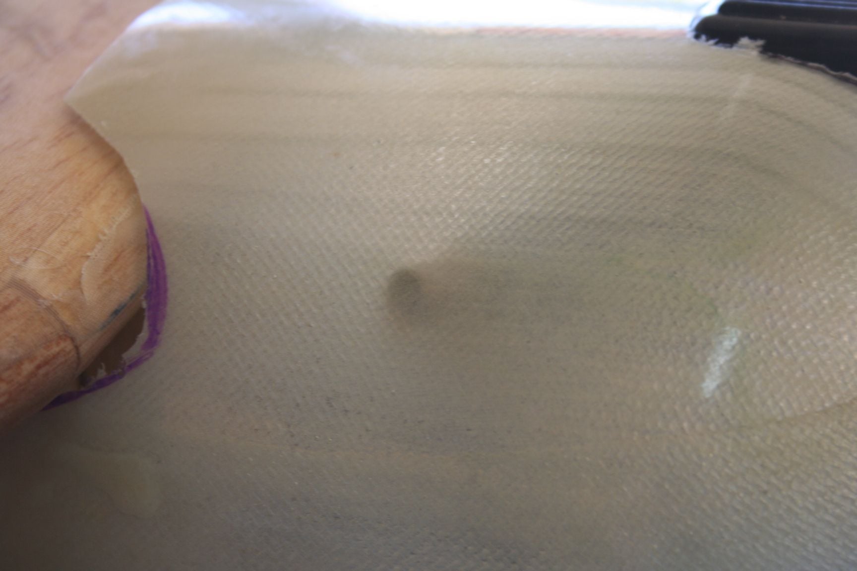
As you can see in the previous pictures, the sheeting extends from the tailwheel opening, until it transitions smoothly into the airfoil of the wing. Some trial fitting and re-trimming may be necessary. With both wing bolts screwed down, lay one of the bottom sheeting sides in-place. (Be sure to line up the inside edge with mid-keel marks and the wing centerline.) Press down on the sheeting to imprint the head of the wing-bolt into the sheeting.
With the other wing-bolt as a visible reference, align your finger over the covered wing bolt and press down firmly.
The exact position of the bolt head is now clearly marked, and can be accurately cut out.
Repeat this process to mark the wing bolt location for the other side.
With the other wing-bolt as a visible reference, align your finger over the covered wing bolt and press down firmly.
The exact position of the bolt head is now clearly marked, and can be accurately cut out.
Repeat this process to mark the wing bolt location for the other side.
08-16-2020, 12:31 PM
#333
Thread Starter
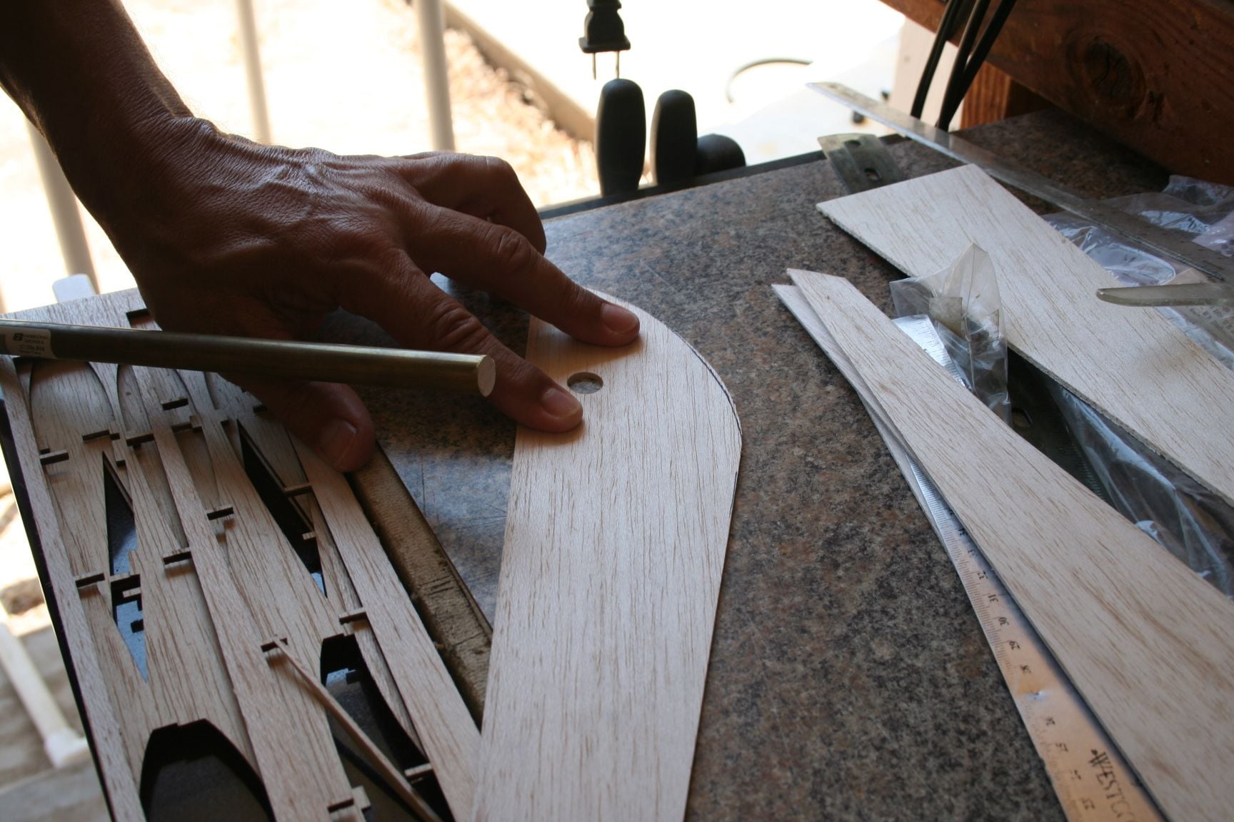
To ensure a "clean" cut, I then used a larger diameter piece of sharpened brass tubing to cut access holes for the wing-bolts. Tim and I enlarged them slightly, using a Dremel and sanding drum.
08-16-2020, 02:19 PM
#334
Thread Starter
The following series of photos detail the gluing of the left and right sides of the bottom sheeting. This sheeting will later be cut at the wing outline, simultaneously making a wing/fuse fairing Tim already glued the starboard side's bottom sheeting before I was able to pick up the camera. So, the instructions will have to incorporate visuals from application of the port side's sheeting. (Because the plane is upside down it will appear on the right side.)
First, trial fit the piece and note all contact points with the sheeting, where CA will need to be applied.
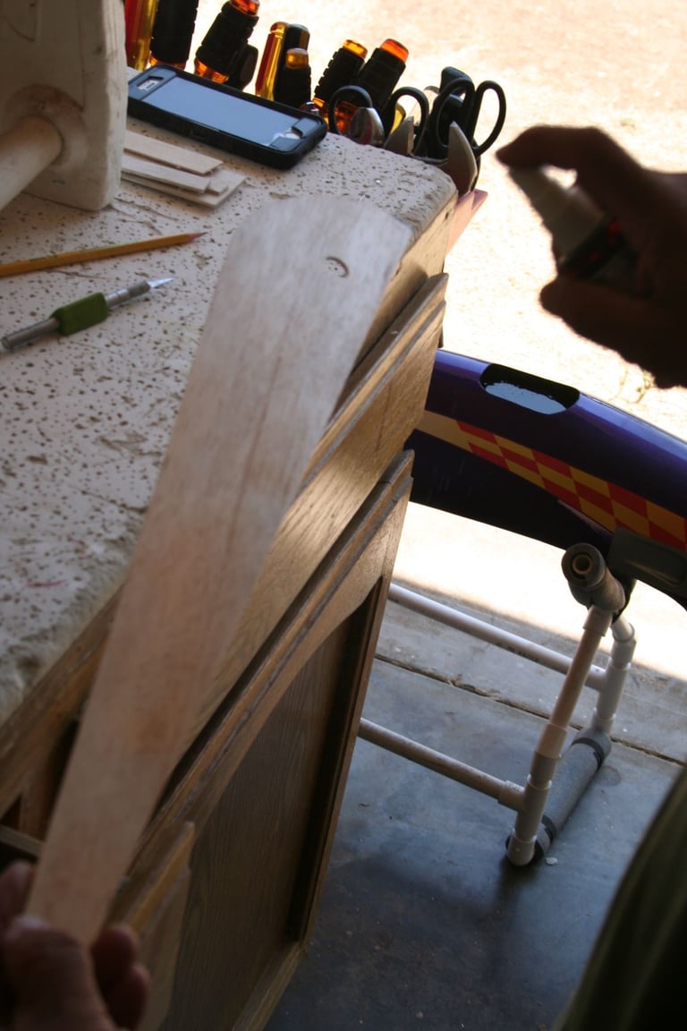
Next, spray a thorough misting of accelerator to the inside portion of the 3/32" balsa sheeting/fairing and set it to the side.
Quickly, run a thin bead of medium CA more towards the outside edge of the half of the keel that this particular piece of sheeting will be applied to; as well as to the beveled balsa at the trailing edge of the wing. (Keep the CA away from the keel's midpoint on the first half, or the glue may squeeze out onto the other half and harden before it can be wiped-away. Thus making it more difficult to apply the other side.)
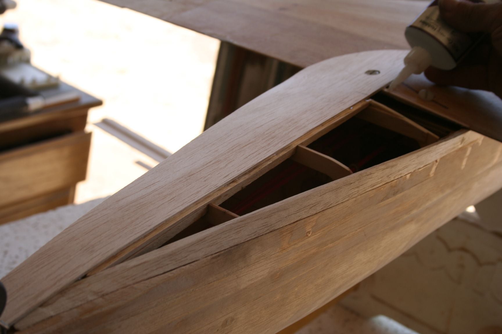
Note that the CA is applied to only half of the keel -- the half which will come into contact with piece of sheeting being glued at that particular time. I was unable to capture images in which we used the mid-points marked in the earlier step for reference when applying glue for the first piece of sheeting. Therefore, in this picture, glue is being applied much closer to the centerline, than should be the case when gluing the first piece. Once the first piece is glued down, CA can now be applied into the corner so that the second piece of sheeting is glued to both the keel and the first piece of sheeting, for a more seamless bond.
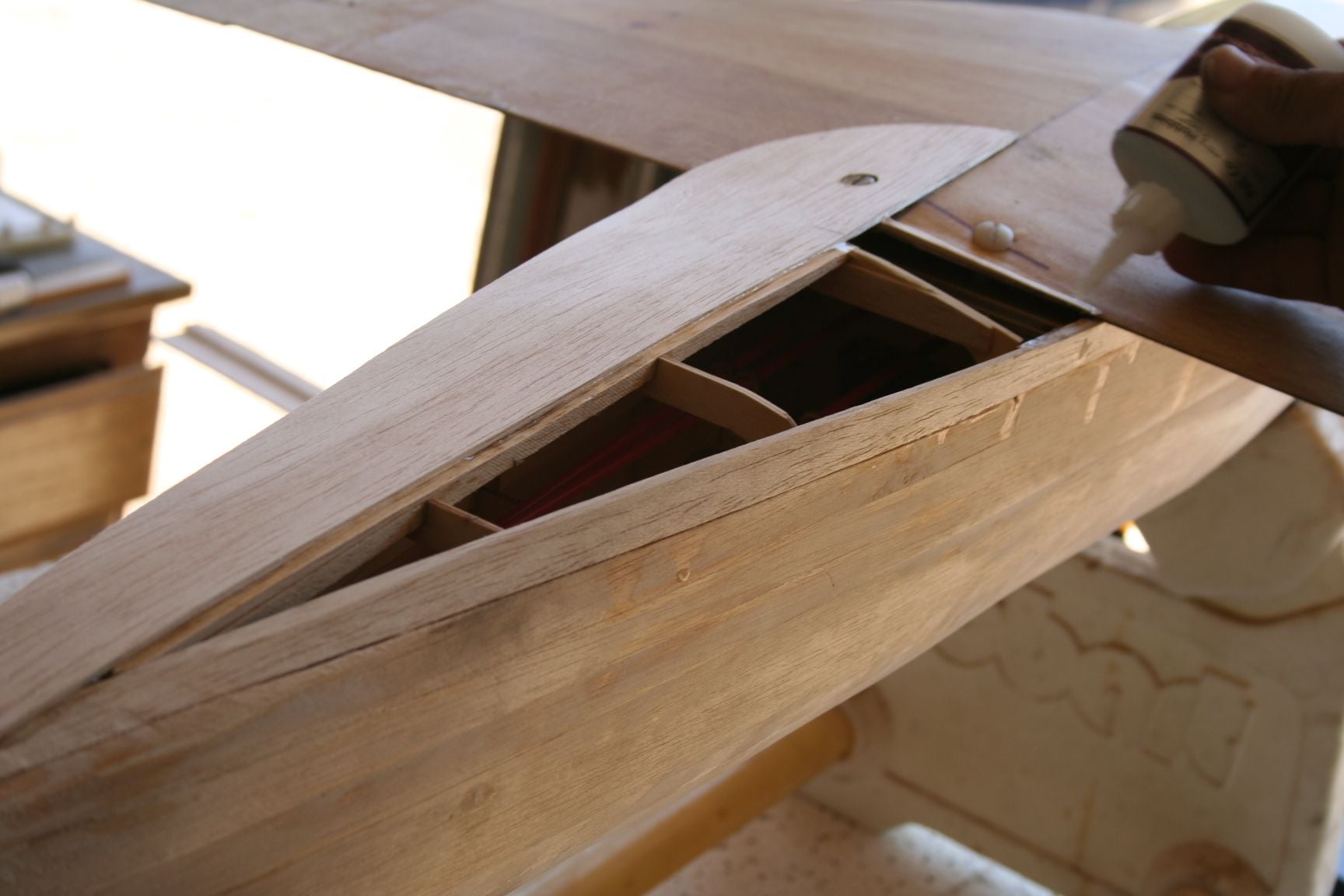
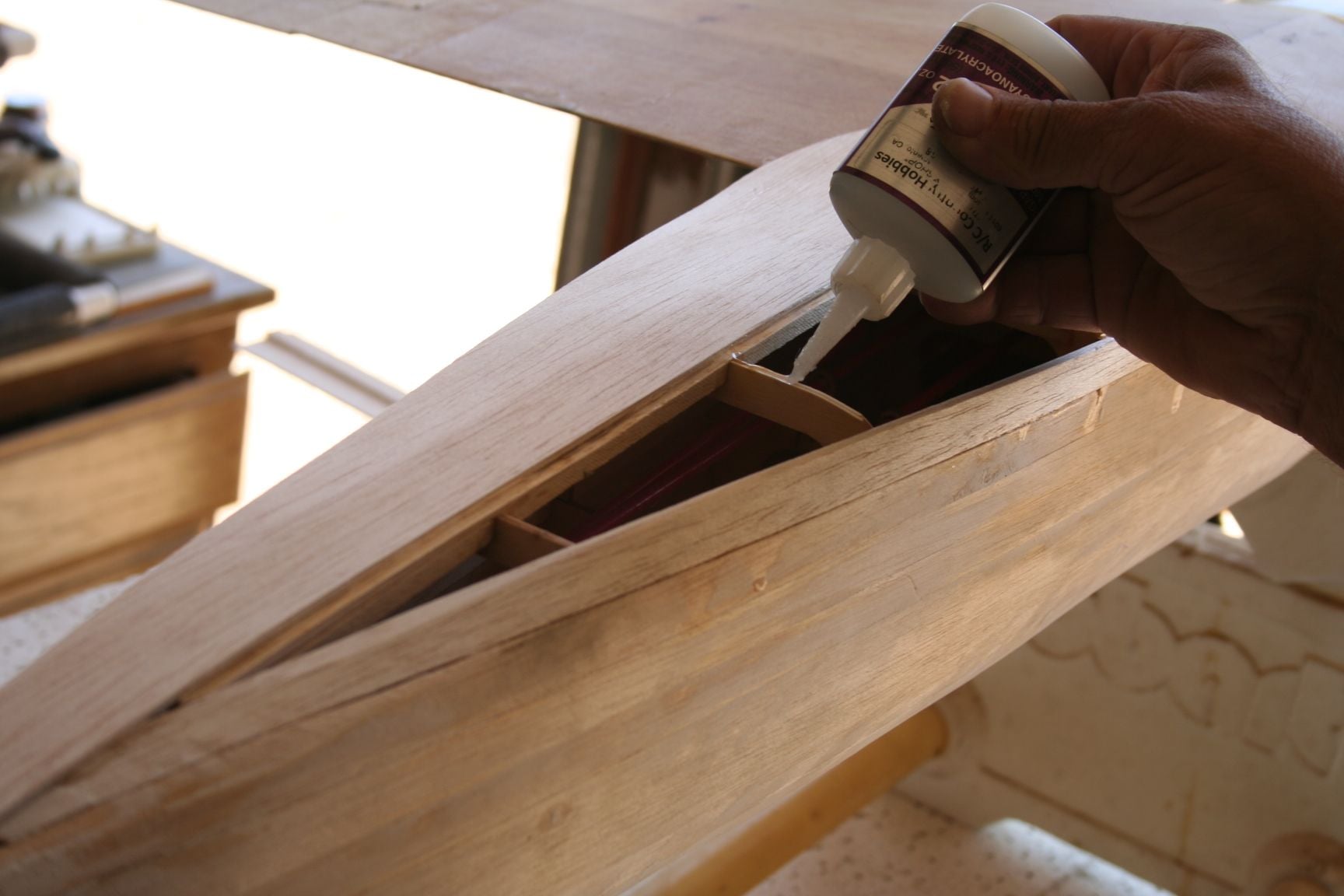
Now, quickly run a thin bead along the outer half of each of the fuse formers; and finally, along the bottom edge of the side planking that will contact the balsa sheet.
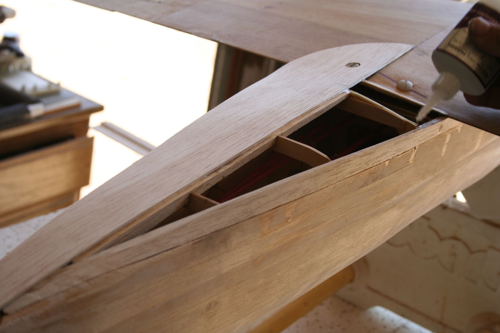
Tim hastily, but methodically, applies medium CA to all edges that will contact the bottom 3/32" sheeting.
First, trial fit the piece and note all contact points with the sheeting, where CA will need to be applied.
Next, spray a thorough misting of accelerator to the inside portion of the 3/32" balsa sheeting/fairing and set it to the side.
Quickly, run a thin bead of medium CA more towards the outside edge of the half of the keel that this particular piece of sheeting will be applied to; as well as to the beveled balsa at the trailing edge of the wing. (Keep the CA away from the keel's midpoint on the first half, or the glue may squeeze out onto the other half and harden before it can be wiped-away. Thus making it more difficult to apply the other side.)
Note that the CA is applied to only half of the keel -- the half which will come into contact with piece of sheeting being glued at that particular time. I was unable to capture images in which we used the mid-points marked in the earlier step for reference when applying glue for the first piece of sheeting. Therefore, in this picture, glue is being applied much closer to the centerline, than should be the case when gluing the first piece. Once the first piece is glued down, CA can now be applied into the corner so that the second piece of sheeting is glued to both the keel and the first piece of sheeting, for a more seamless bond.
Now, quickly run a thin bead along the outer half of each of the fuse formers; and finally, along the bottom edge of the side planking that will contact the balsa sheet.
Tim hastily, but methodically, applies medium CA to all edges that will contact the bottom 3/32" sheeting.
08-16-2020, 02:39 PM
#335
Thread Starter
Once the CA has been applied, use the mid-points drawn on the keel and the opening for the tailwheel as references to very quickly align the bottom sheeting, before pressing and holding it down. (Remember: there is accelerator on the inside of the sheeting, so don't make actual contact until you are sure that the piece is properly aligned.)
In the pictures that follow, Tim is pressing and briefly holding the sheeting against the fuse. I found it easier working from the keel, outward; and from the rear of the fuse towards the wing. But, accelerator is involved, so one must work fast!
In the pictures that follow, Tim is pressing and briefly holding the sheeting against the fuse. I found it easier working from the keel, outward; and from the rear of the fuse towards the wing. But, accelerator is involved, so one must work fast!
08-16-2020, 03:00 PM
#336
Thread Starter
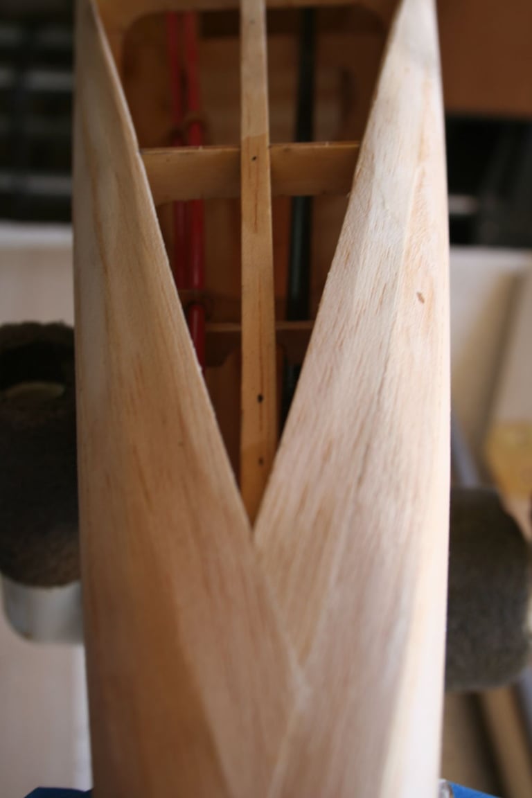
Once done capturing Tim gluing his second piece of bottom sheeting, I turn my attention to gluing mine. Here is a shot of my CzechMate with its sheeting glued-down.
In the background of many of these shots is a crash-and-rebuild project I am also working on. It is a modified World Models ARF that I have transformed into the RB-51 "Red Baron" Race #5, through a number of custom modifications, including: a new cowl with the intake on top, raised/enlarged vertical fin and rudder, cropped wing, etc. In a cradle on the floor in a couple shots, you might notice Tim's beautiful purple "RareBear." He brought it with him on this day to share his progress with me. (See post #334 and and an upcoming shot.)
In the background of many of these shots is a crash-and-rebuild project I am also working on. It is a modified World Models ARF that I have transformed into the RB-51 "Red Baron" Race #5, through a number of custom modifications, including: a new cowl with the intake on top, raised/enlarged vertical fin and rudder, cropped wing, etc. In a cradle on the floor in a couple shots, you might notice Tim's beautiful purple "RareBear." He brought it with him on this day to share his progress with me. (See post #334 and and an upcoming shot.)
08-16-2020, 03:22 PM
#337
Thread Starter
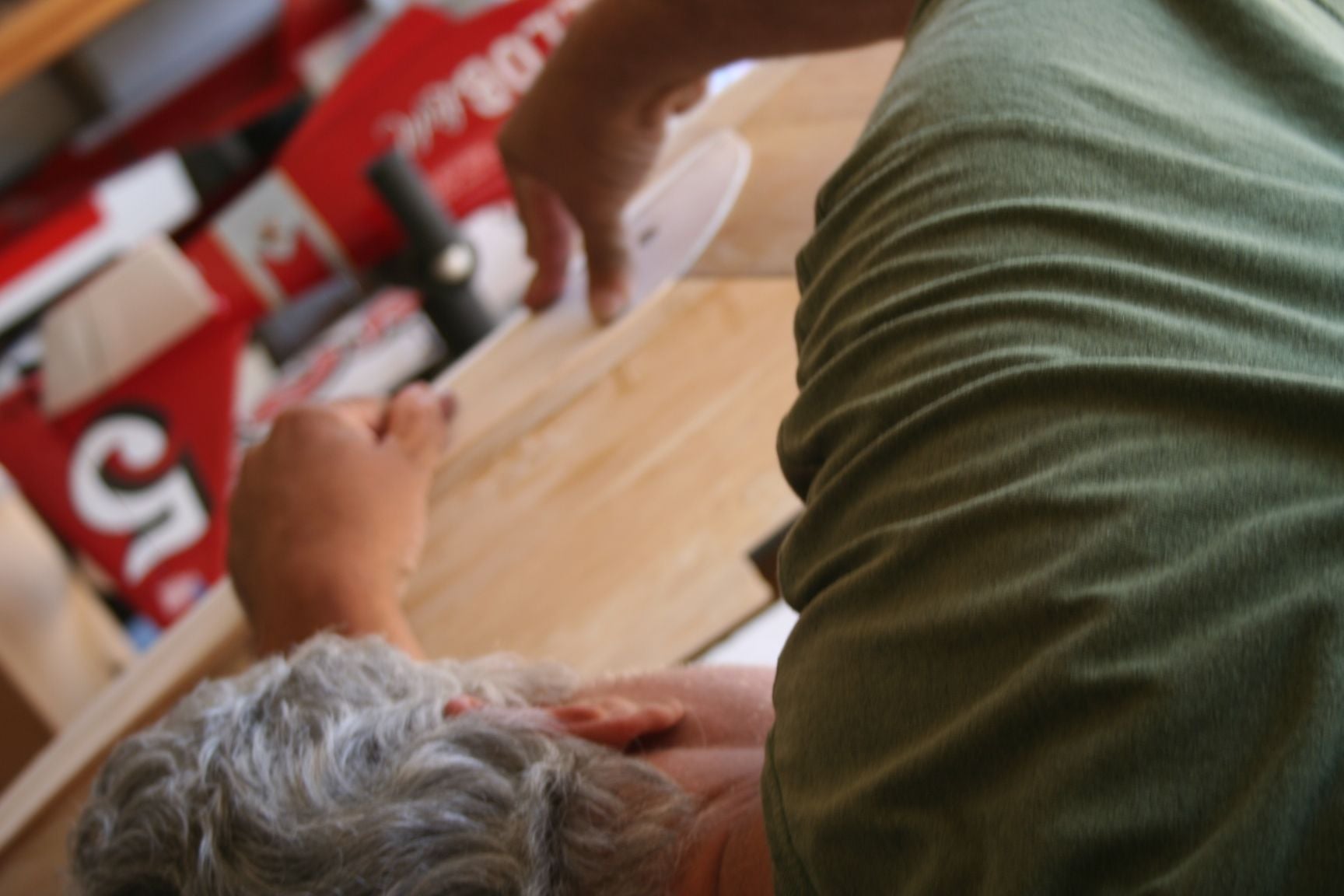
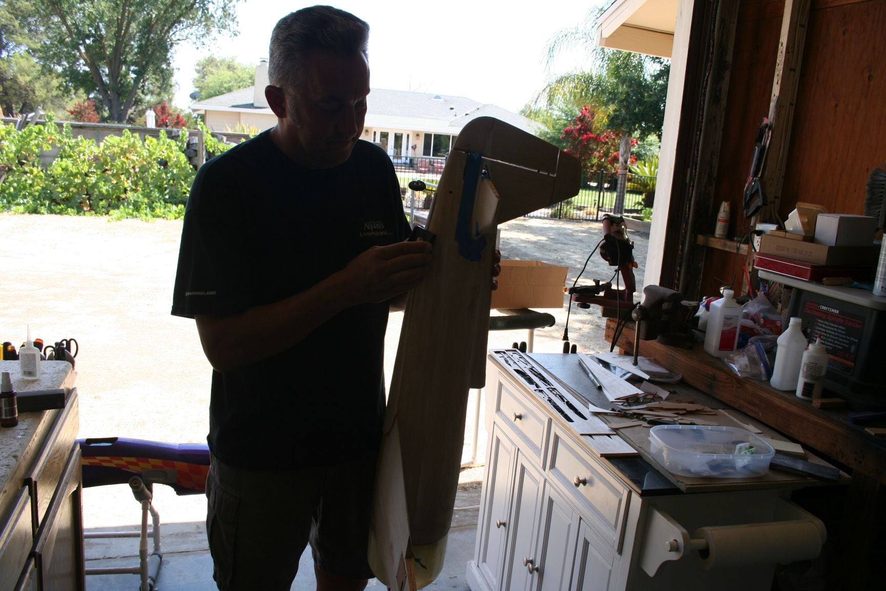
Tim considers how he wants to attack blending the excess bottom sheeting into the contours of the fuse.
He's a "cutter," and so like a true surgeon, he calls for his #11 "scalpel" and starts slicing away. (With a new blade, of course!)
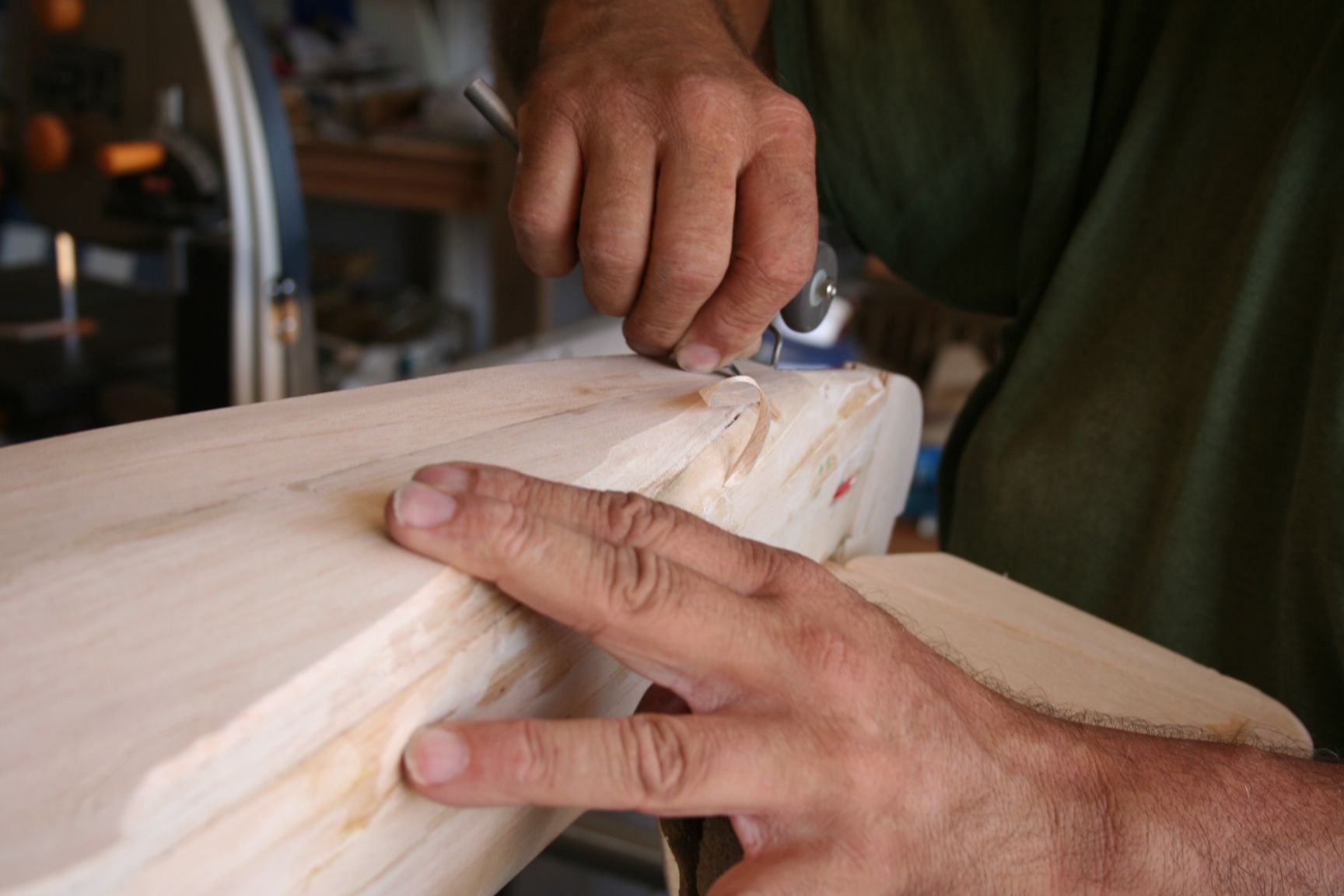
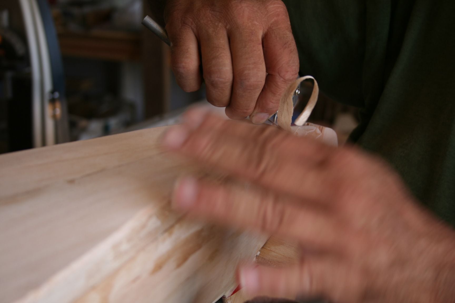
Tim is channeling his inner Edward Scissorhands . . . The hands are a blur, and balsa furiously flies away from the fuse in all directions, like leaves flying from of one of Edward's topiary masterpieces!
(Okay, admittedly I exaggerate in simile for dramatic effect because it fits the imagery of the picture. Tim is a craftsman, after all.)
He's a "cutter," and so like a true surgeon, he calls for his #11 "scalpel" and starts slicing away. (With a new blade, of course!)
Tim is channeling his inner Edward Scissorhands . . . The hands are a blur, and balsa furiously flies away from the fuse in all directions, like leaves flying from of one of Edward's topiary masterpieces!
(Okay, admittedly I exaggerate in simile for dramatic effect because it fits the imagery of the picture. Tim is a craftsman, after all.)
08-16-2020, 04:03 PM
#338
Thread Starter
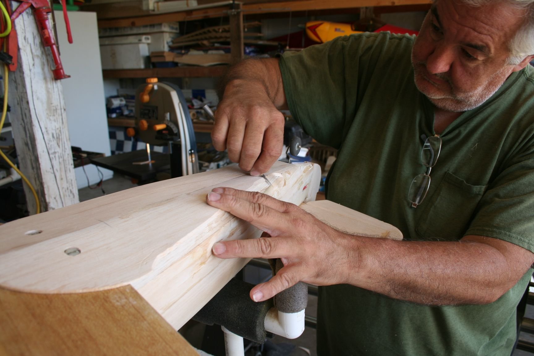
Tim's skill as a professional woodworker pays off. He has clean cuts and does a beautiful job!
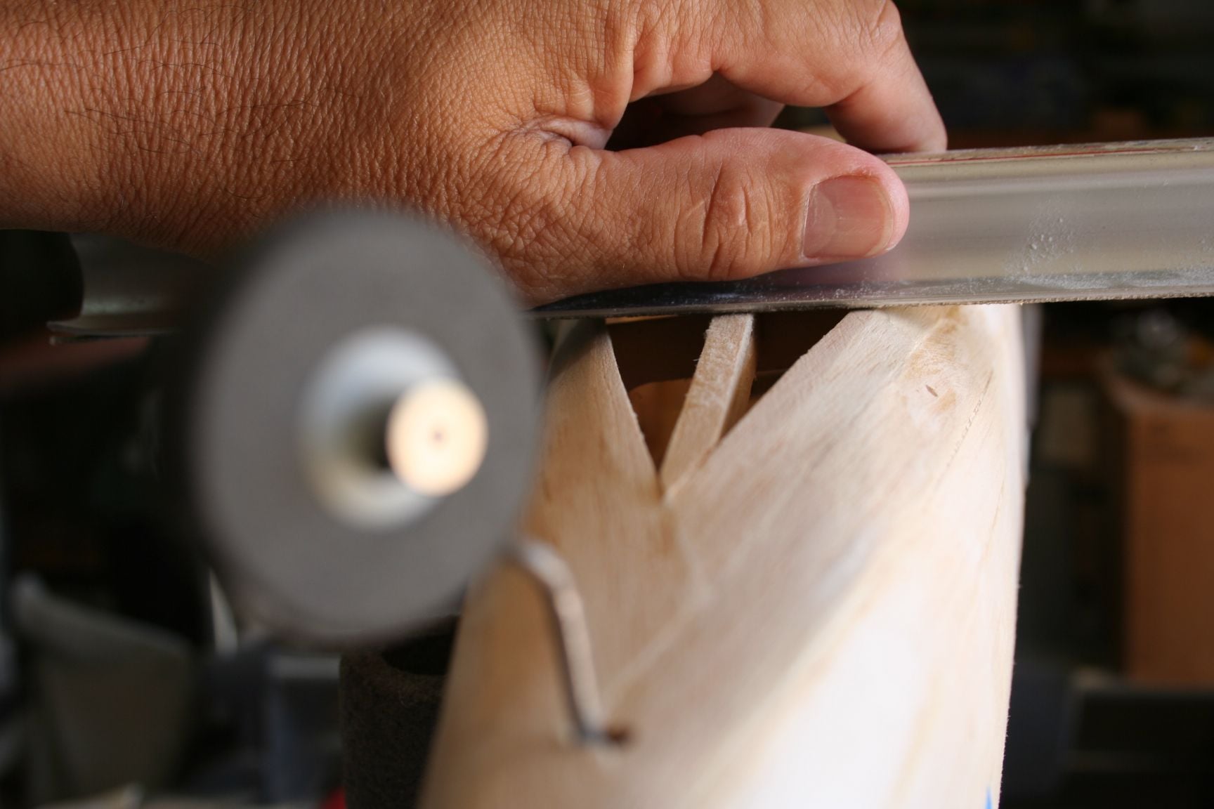
I however am an amateur woodworker, and have occasionally encountered issues in the past when slicing balsa in this manner -- especially when cutting into the grain. So my approach was more like a 5-year-old using training wheels to avoid crashes on a bicycle:
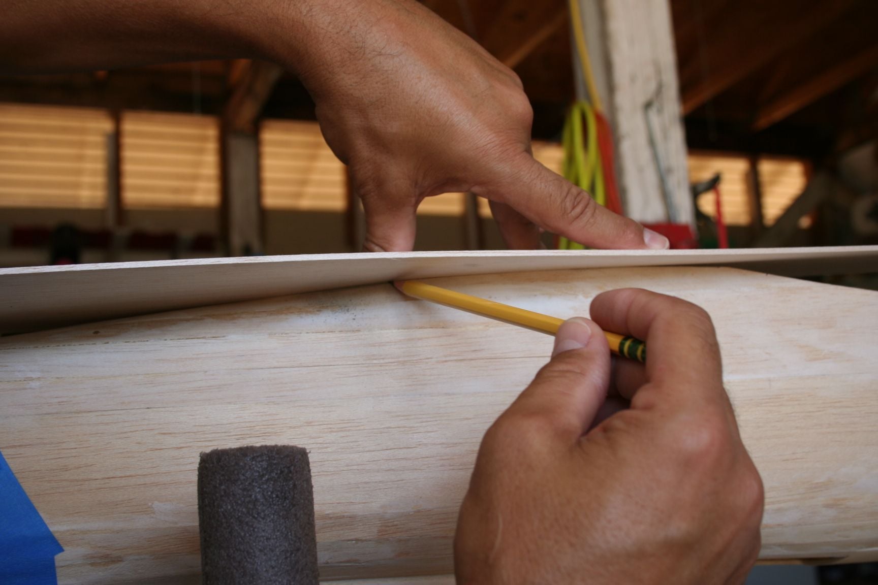
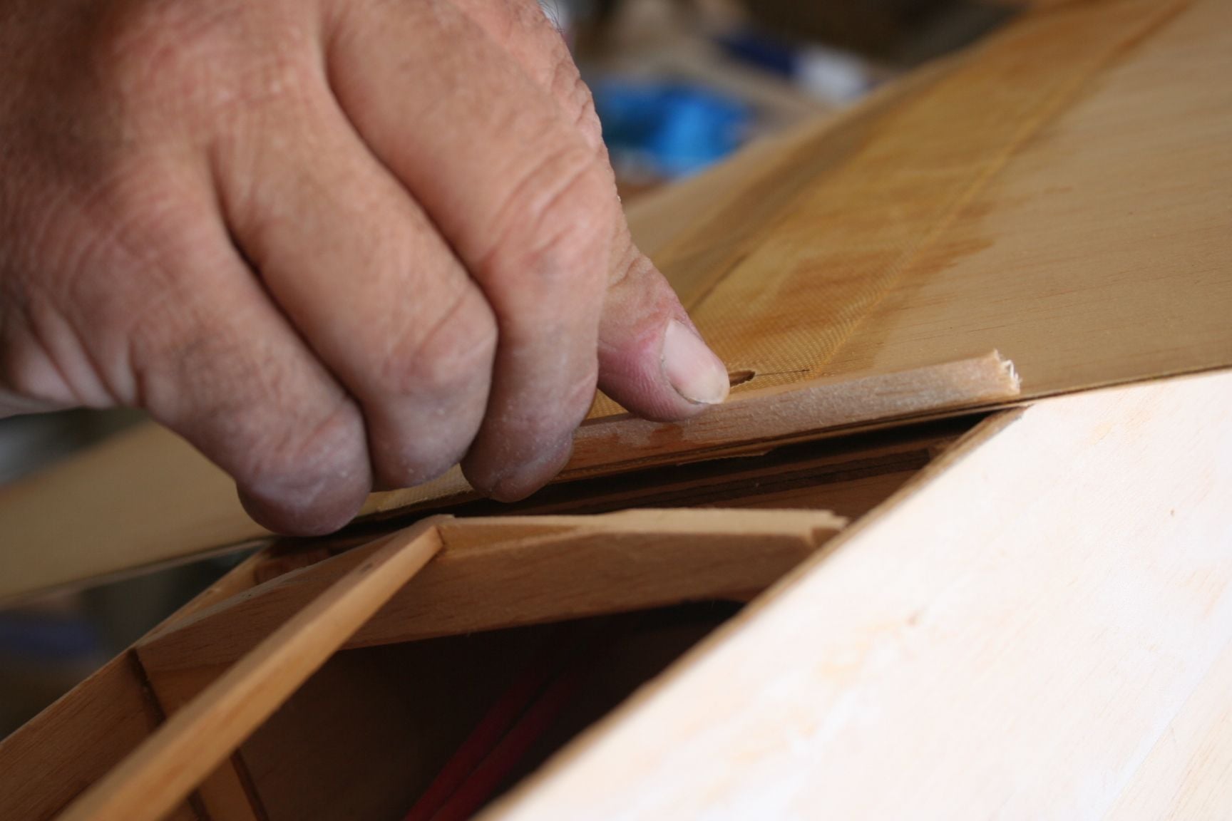
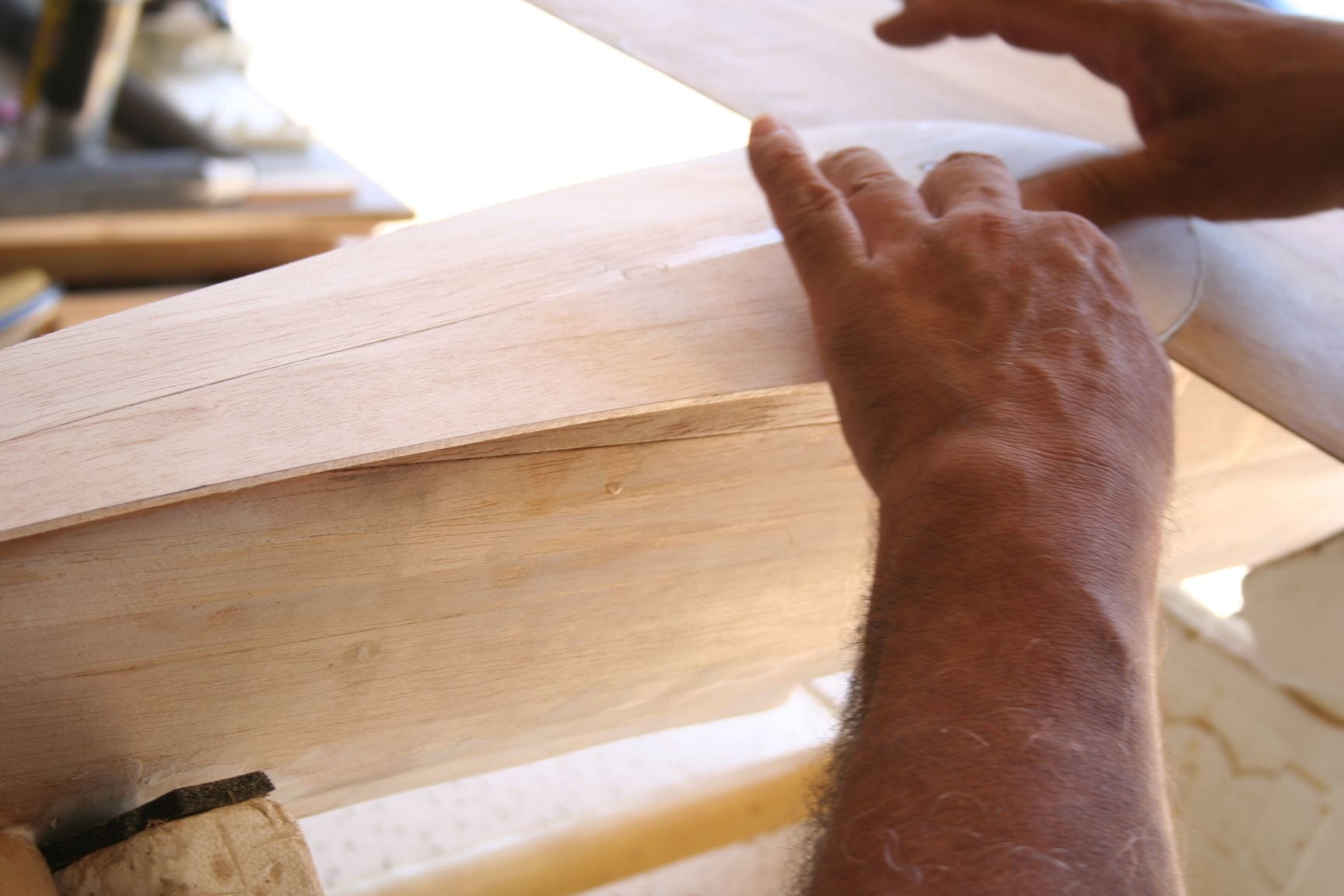
Beings the grain is running parallel to the keel, but I am forced to trim it at an angle, I used a straight edge as a guide -- resistance to help my knife better avoid following a potential split or other weak spot, and accidentally cutting too deeply into the sheeting. I also cut from the front, towards the rear of the fuse, so my knife won't "detour" into the path of least resistance and "bite" into the grain; thus slicing side of my fuse or accidentally splitting my sheeting. I don't know if I am being effective in wording this clearly and accurately or not, but in this way, I am essentially trimming off the un-needed tips of each fiber, rather than cutting into them more towards their base. All I can say is for what it is worth, "It works better for me." As always, you should do what works for you.
Note I am trimming at a bevel.
The alignment of the cut-outs for the wing bolts are also visible in this shot.
I trimmed the sheeting "close," with an Exacto knife. But will finish with a razor plane and sanding block.
I however am an amateur woodworker, and have occasionally encountered issues in the past when slicing balsa in this manner -- especially when cutting into the grain. So my approach was more like a 5-year-old using training wheels to avoid crashes on a bicycle:
Beings the grain is running parallel to the keel, but I am forced to trim it at an angle, I used a straight edge as a guide -- resistance to help my knife better avoid following a potential split or other weak spot, and accidentally cutting too deeply into the sheeting. I also cut from the front, towards the rear of the fuse, so my knife won't "detour" into the path of least resistance and "bite" into the grain; thus slicing side of my fuse or accidentally splitting my sheeting. I don't know if I am being effective in wording this clearly and accurately or not, but in this way, I am essentially trimming off the un-needed tips of each fiber, rather than cutting into them more towards their base. All I can say is for what it is worth, "It works better for me." As always, you should do what works for you.
Note I am trimming at a bevel.
The alignment of the cut-outs for the wing bolts are also visible in this shot.
I trimmed the sheeting "close," with an Exacto knife. But will finish with a razor plane and sanding block.
Last edited by Iron Dog; 08-16-2020 at 04:06 PM.
 09-03-2020, 09:09 PM
#340
Thread Starter
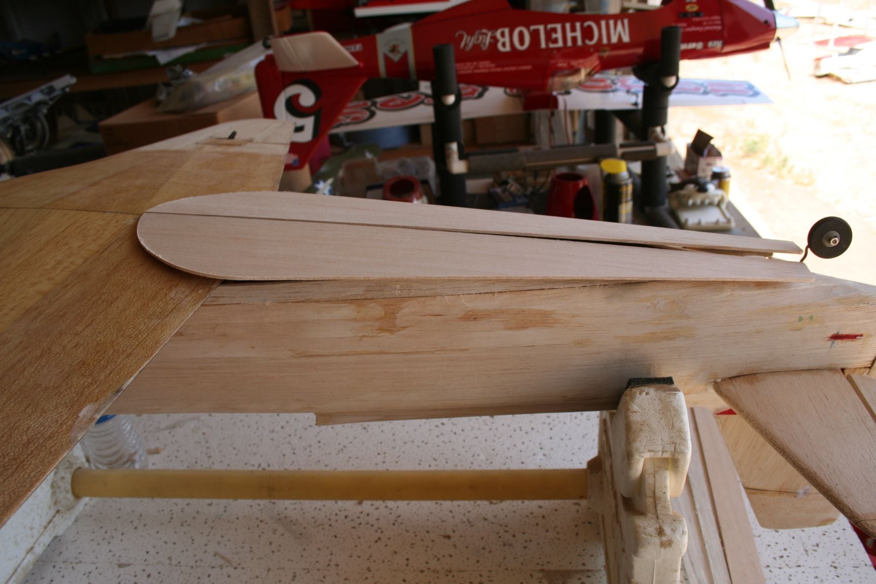
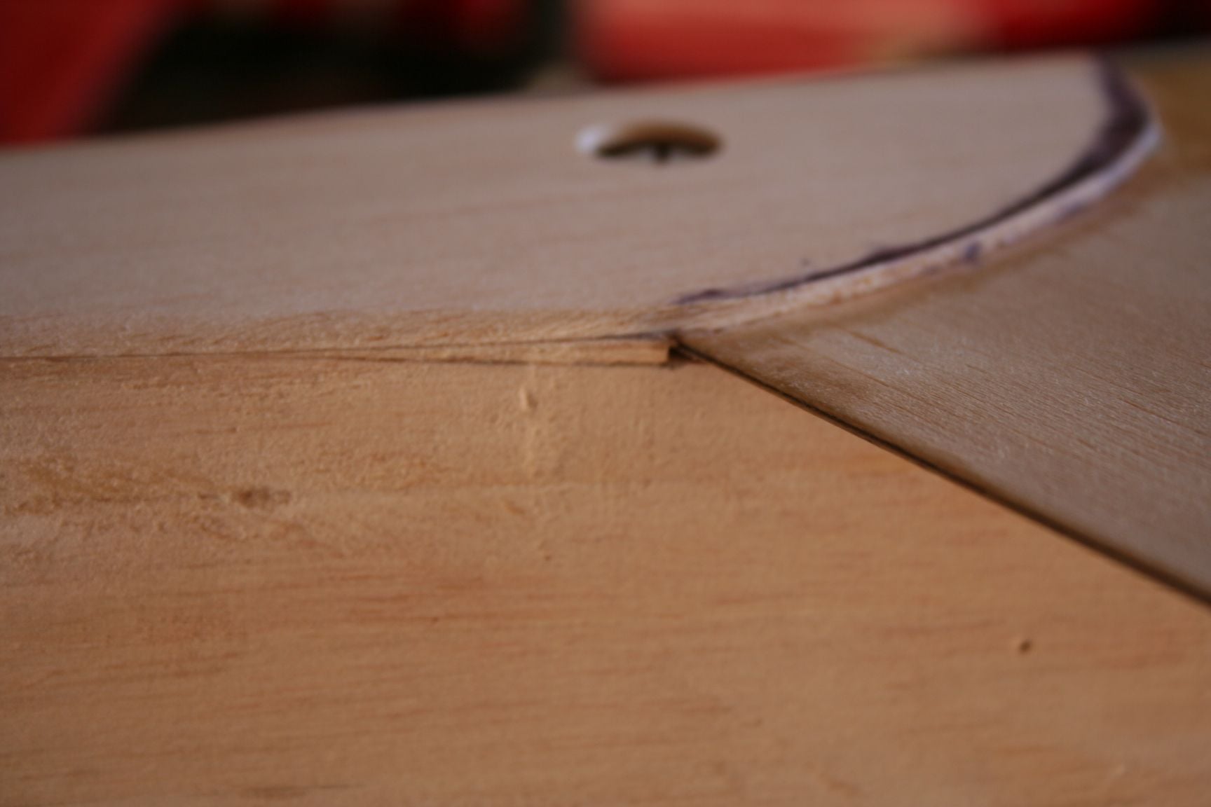
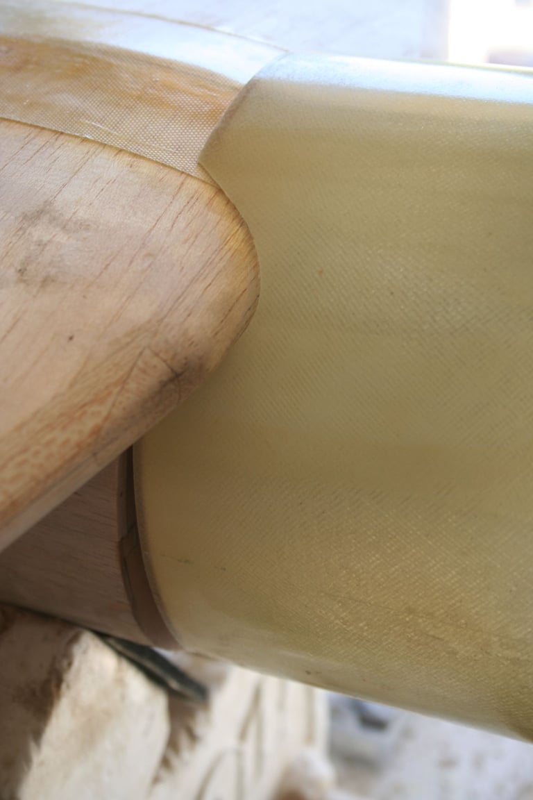
Back about the time captured in Post #331, when I was trial fitting the bottom sheeting, I noticed a gap -- the thickness of the wing's trailing edge. (Tim's CzechMate is pictured to illustrate, below.)
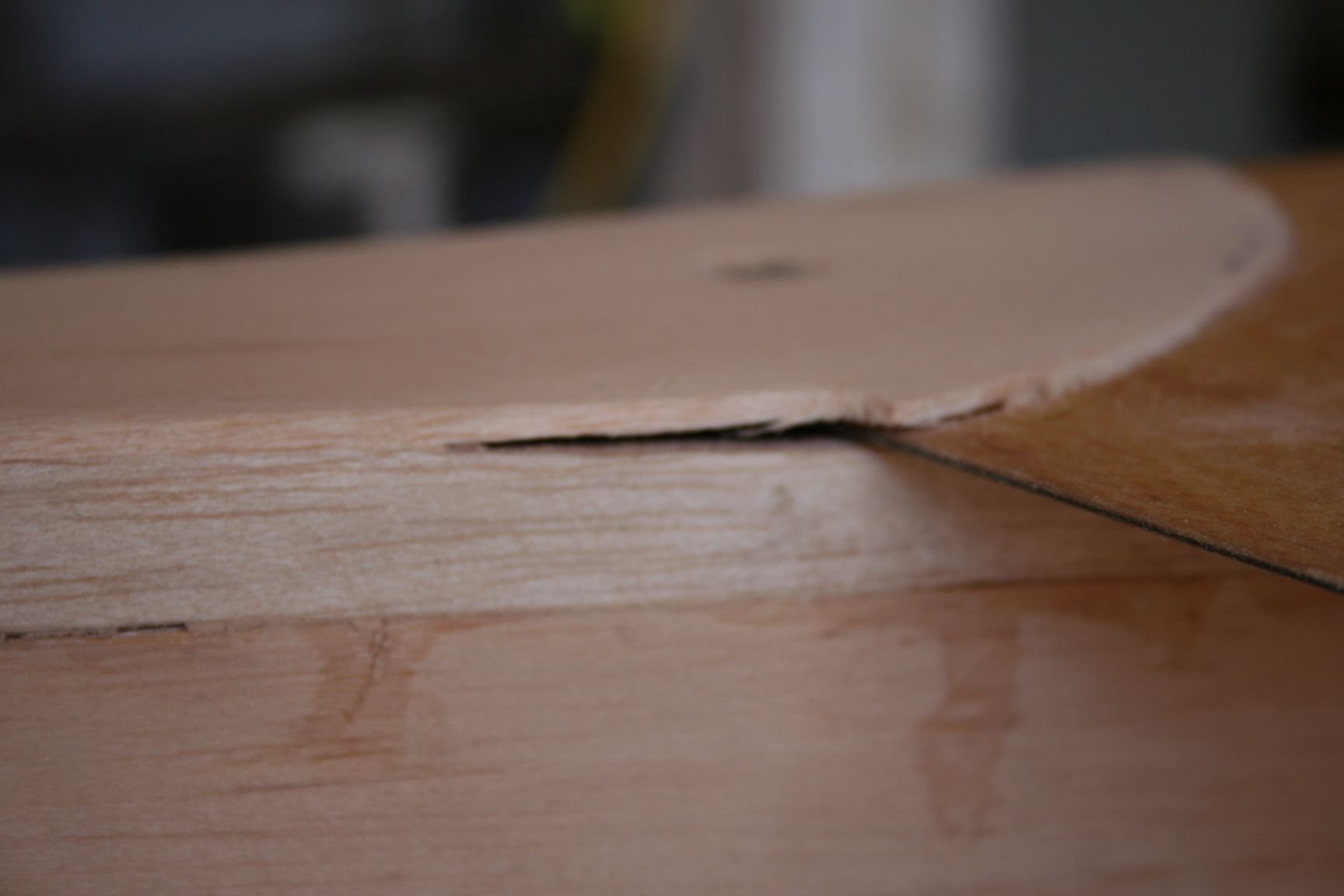
I chose to close this gap by gluing-in some scrap balsa, and sanding it to a bevel, before attaching the wing.
Okay, with that oversight now corrected, "back to our regularly scheduled program" . . .
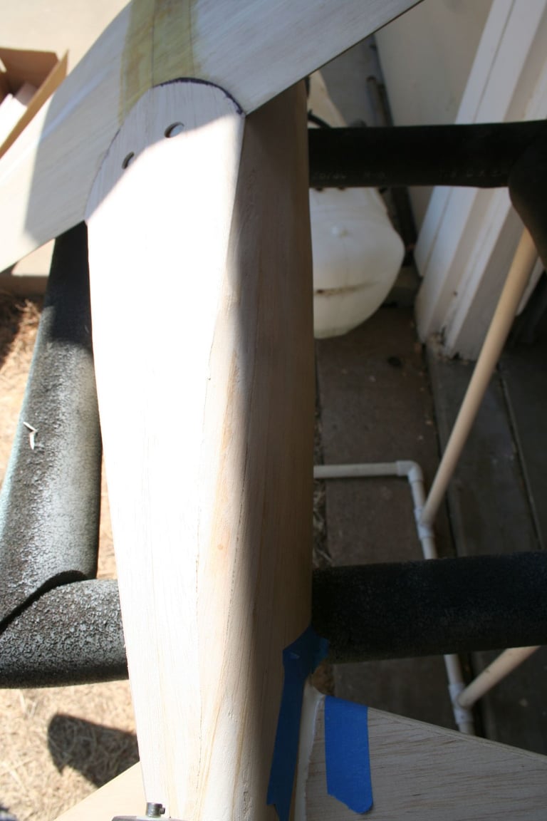
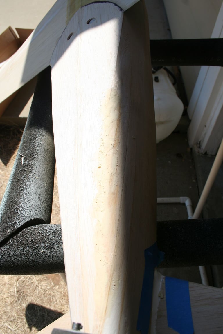
Shots of me razor-planing the bottom sheeting.

I chose to close this gap by gluing-in some scrap balsa, and sanding it to a bevel, before attaching the wing.
Okay, with that oversight now corrected, "back to our regularly scheduled program" . . .
Shots of me razor-planing the bottom sheeting.
Last edited by Iron Dog; 09-03-2020 at 09:27 PM.
 09-03-2020, 09:45 PM
#342
Thread Starter
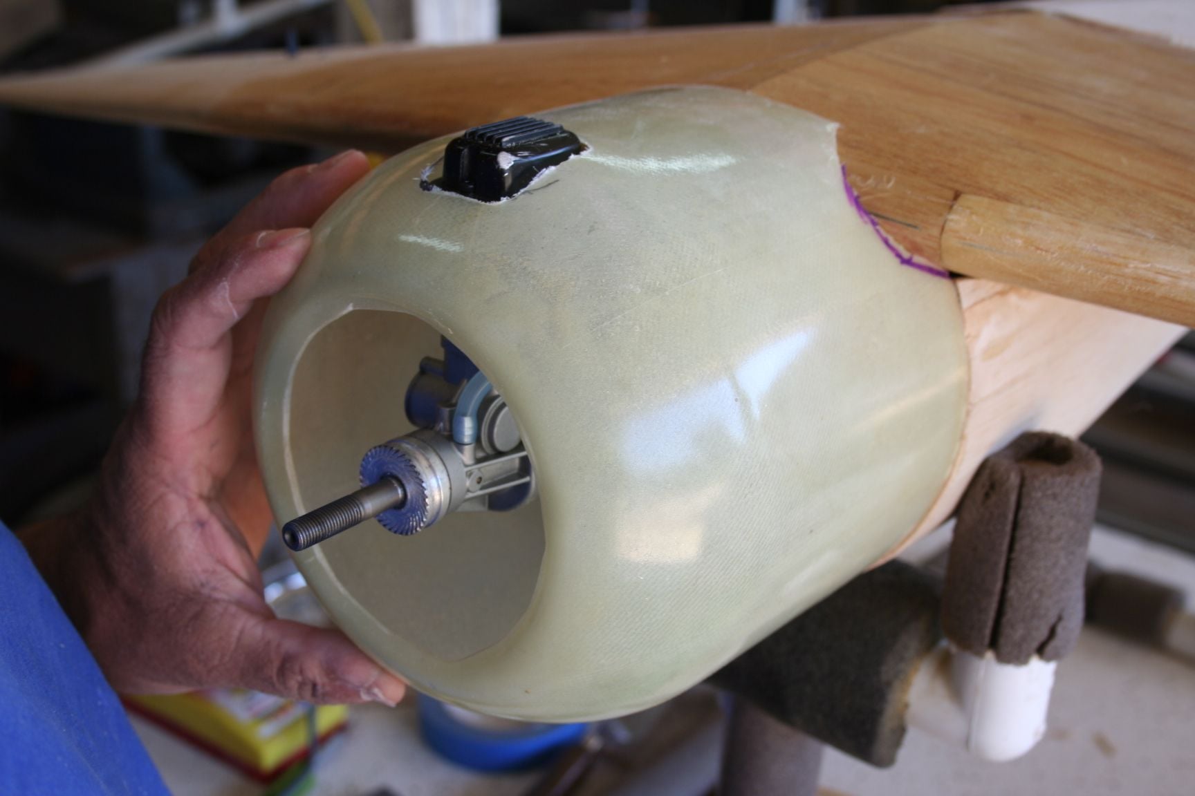
Time to mount the engine and cut the cowl for clearances.
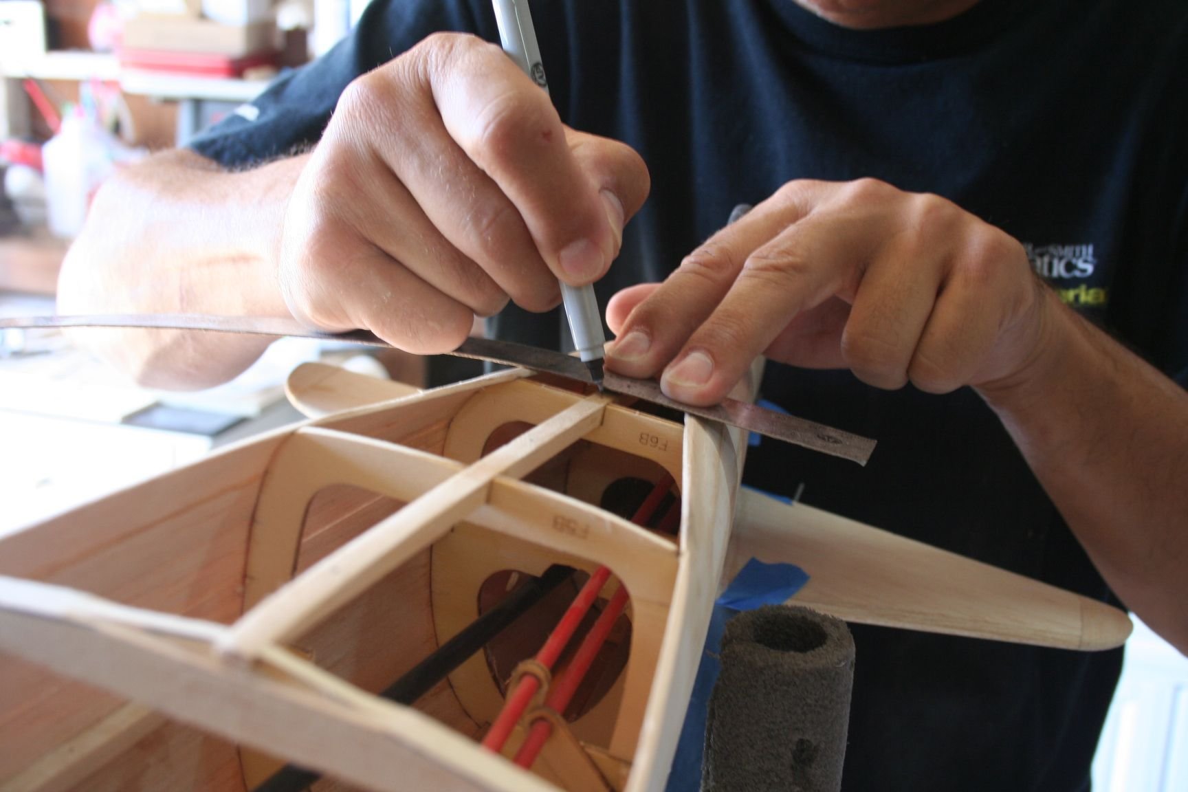
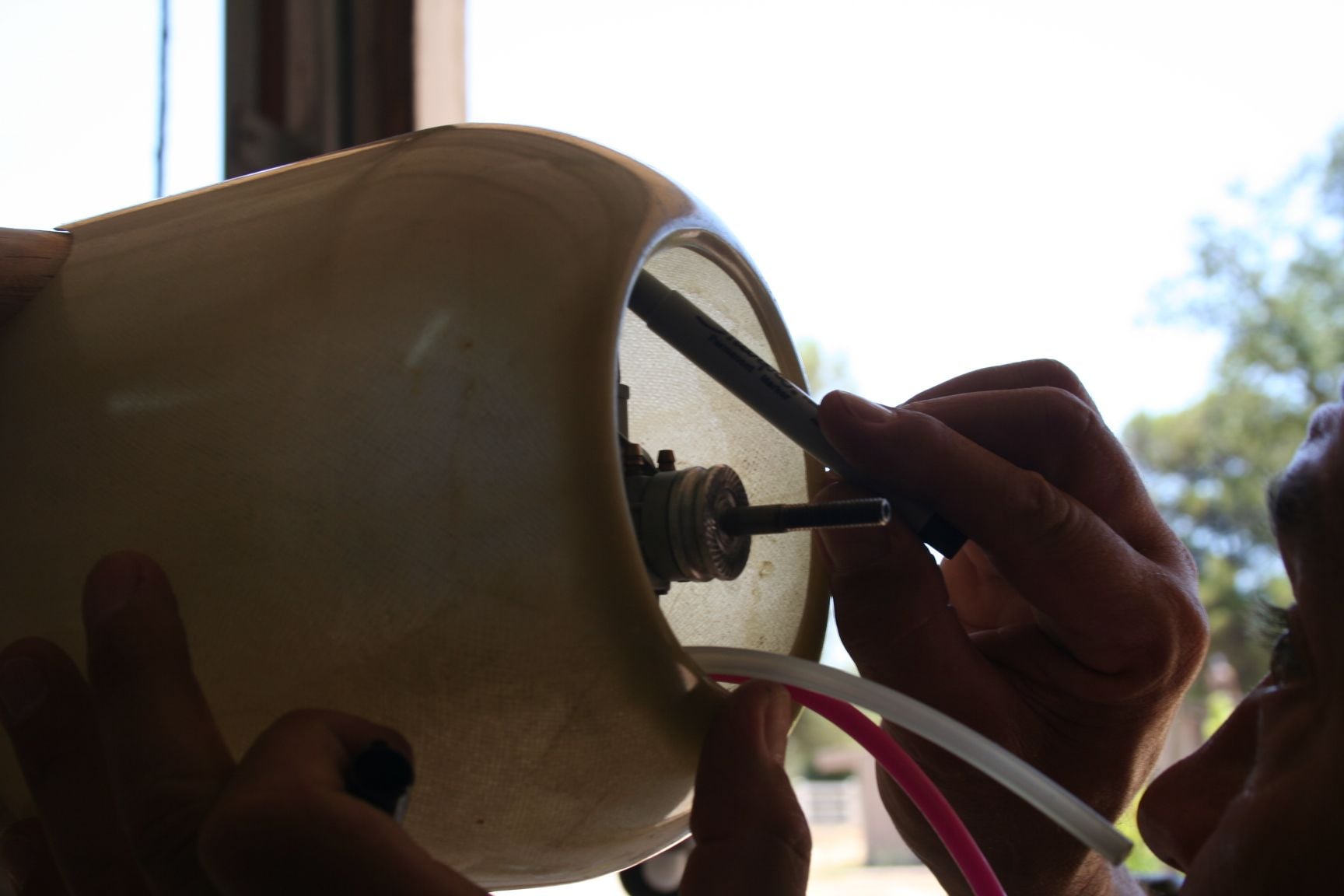
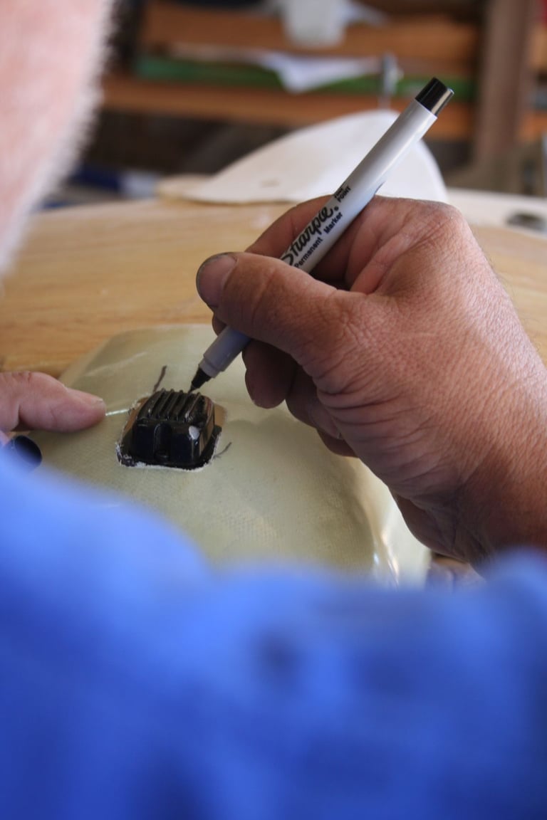
I mounted my YS .70 on a Dave Brown engine mount (the longer or more extended version of the two engine mounts this company offers for this engine displacement), without the exhaust pipe nor the needle valve. The cowl was placed over the engine, as much as possible. Tim and I used a Sharpie marker or a pencil to equal effect to outline the valve cover on the inside of the cowl. Then, used a Dremel fitted with a cut-off wheel to rough-cut a clearance hole.
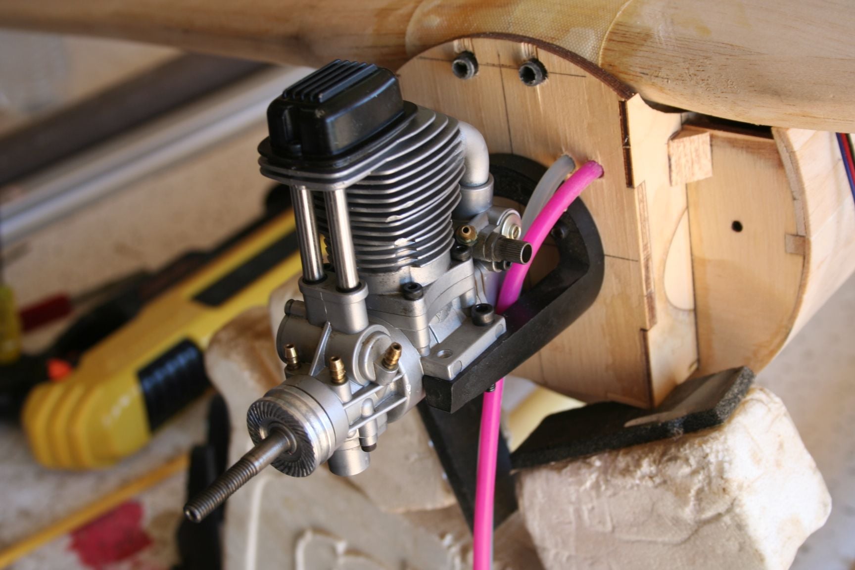
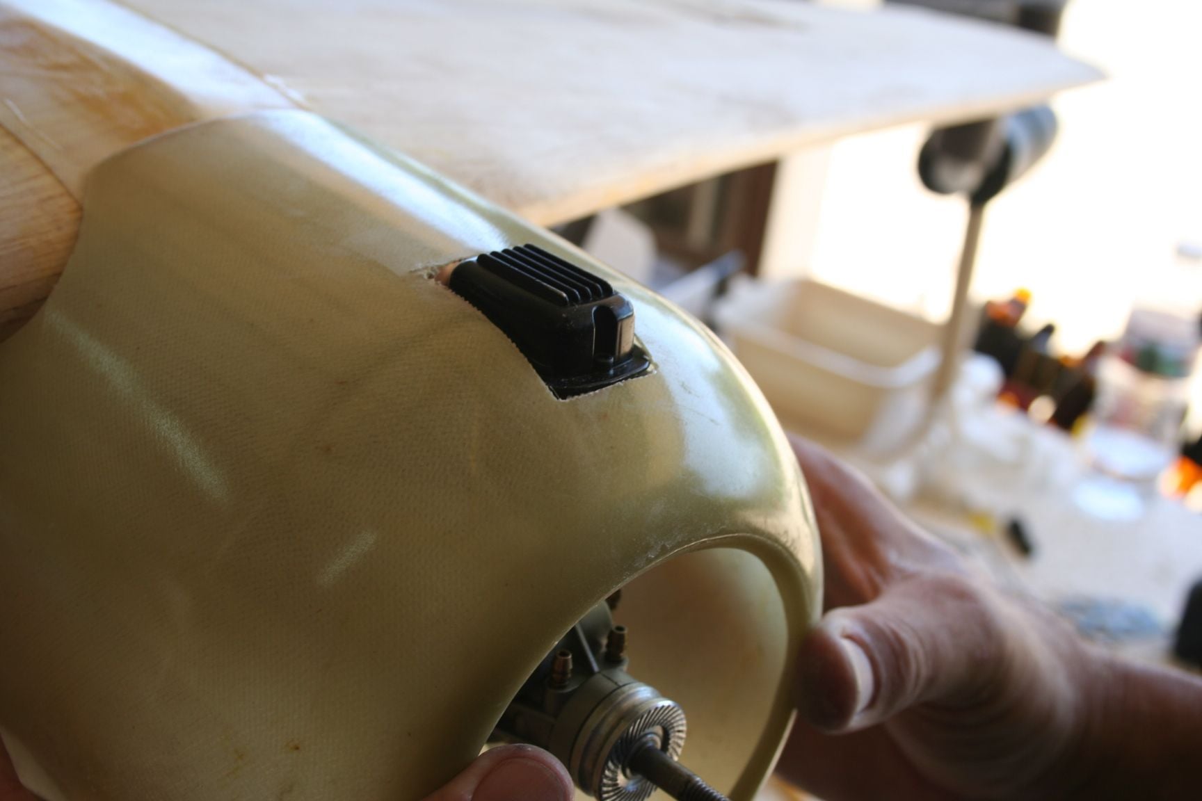
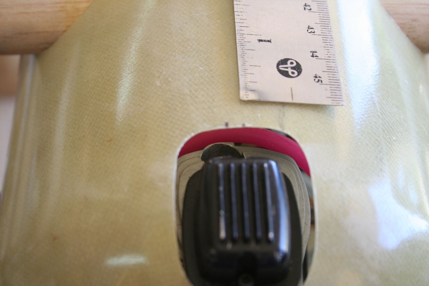
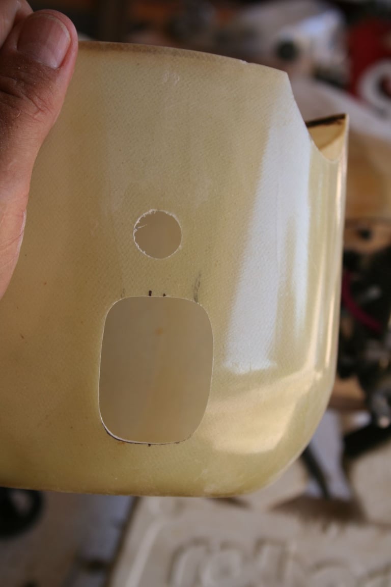
It almost fits flush -- nearly clearing the valve cover, but not quite.
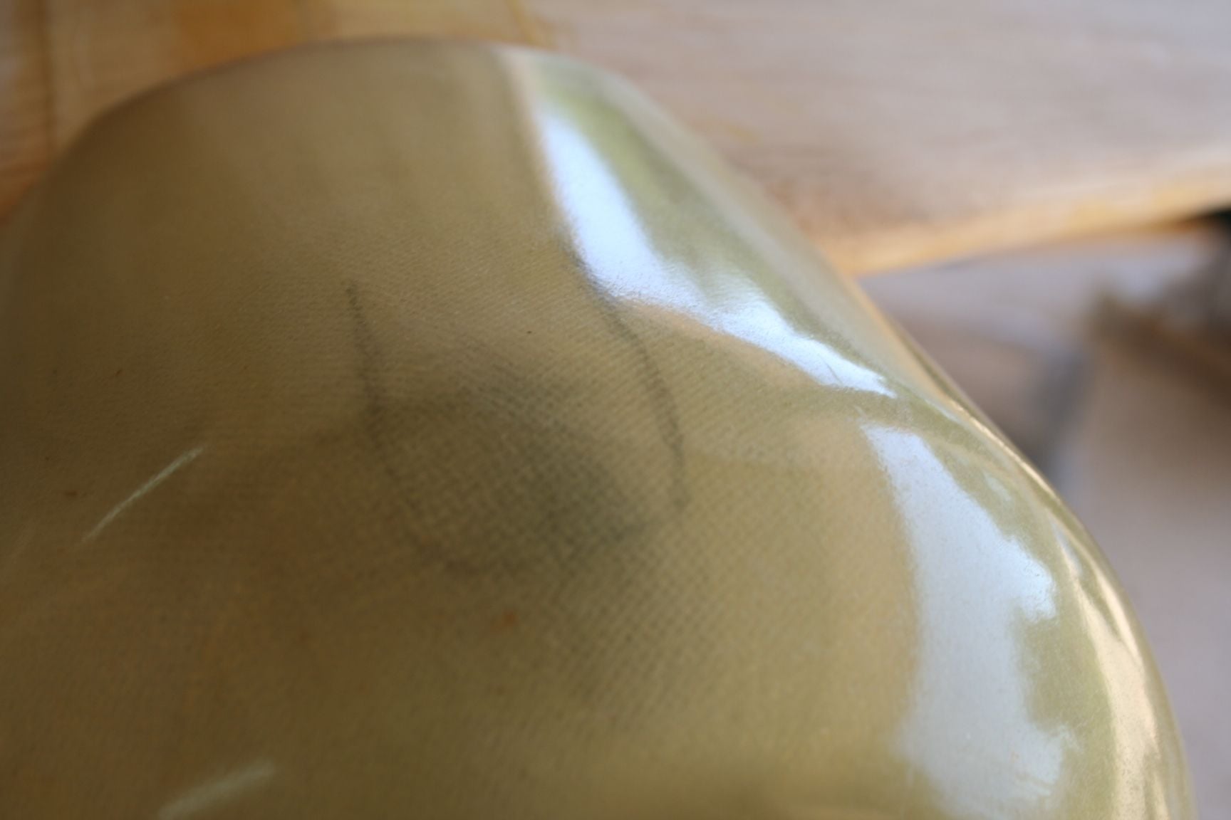
View from outside of my cowl.
View from inside of Tim's cowl.
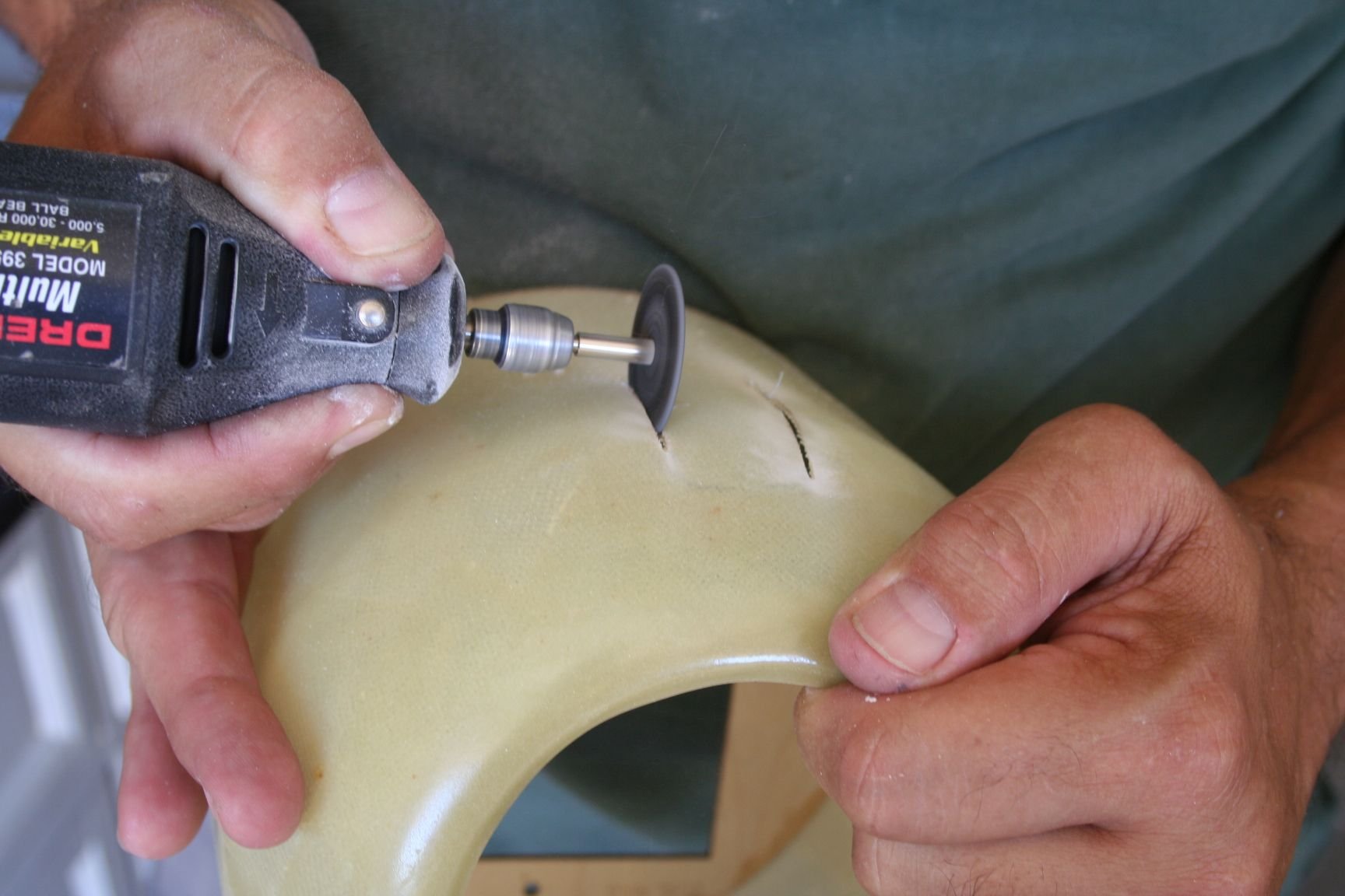
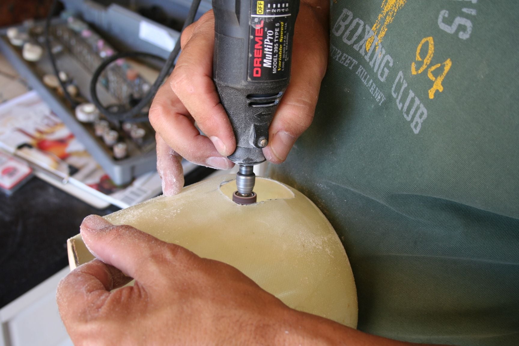
Here, I am cutting-out the valve cover clearance hole.
I mounted my YS .70 on a Dave Brown engine mount (the longer or more extended version of the two engine mounts this company offers for this engine displacement), without the exhaust pipe nor the needle valve. The cowl was placed over the engine, as much as possible. Tim and I used a Sharpie marker or a pencil to equal effect to outline the valve cover on the inside of the cowl. Then, used a Dremel fitted with a cut-off wheel to rough-cut a clearance hole.
It almost fits flush -- nearly clearing the valve cover, but not quite.
View from outside of my cowl.
View from inside of Tim's cowl.
Here, I am cutting-out the valve cover clearance hole.
Last edited by Iron Dog; 09-03-2020 at 10:55 PM.
09-03-2020, 09:56 PM
#343
Thread Starter
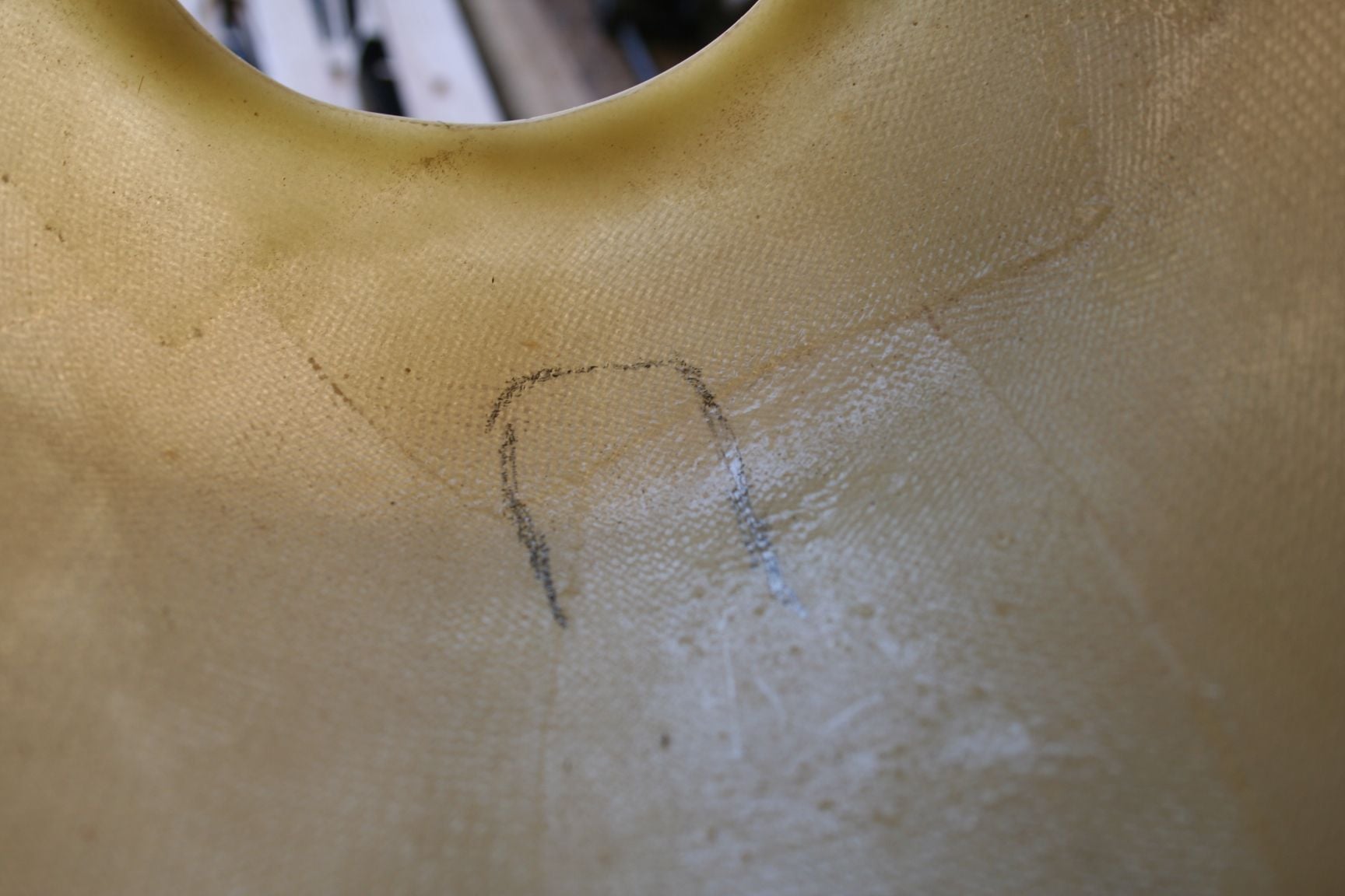
As is usually the case with prototypes, there is quite a bit of re-fitting, outlining more to cut/sand away, re-fit again, and so on. Do this until satisfied with the "fit" and amount of clearance for your engine application.
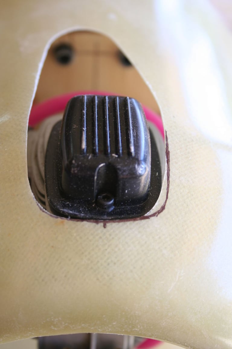
Initial trial fit after original opening was cut.
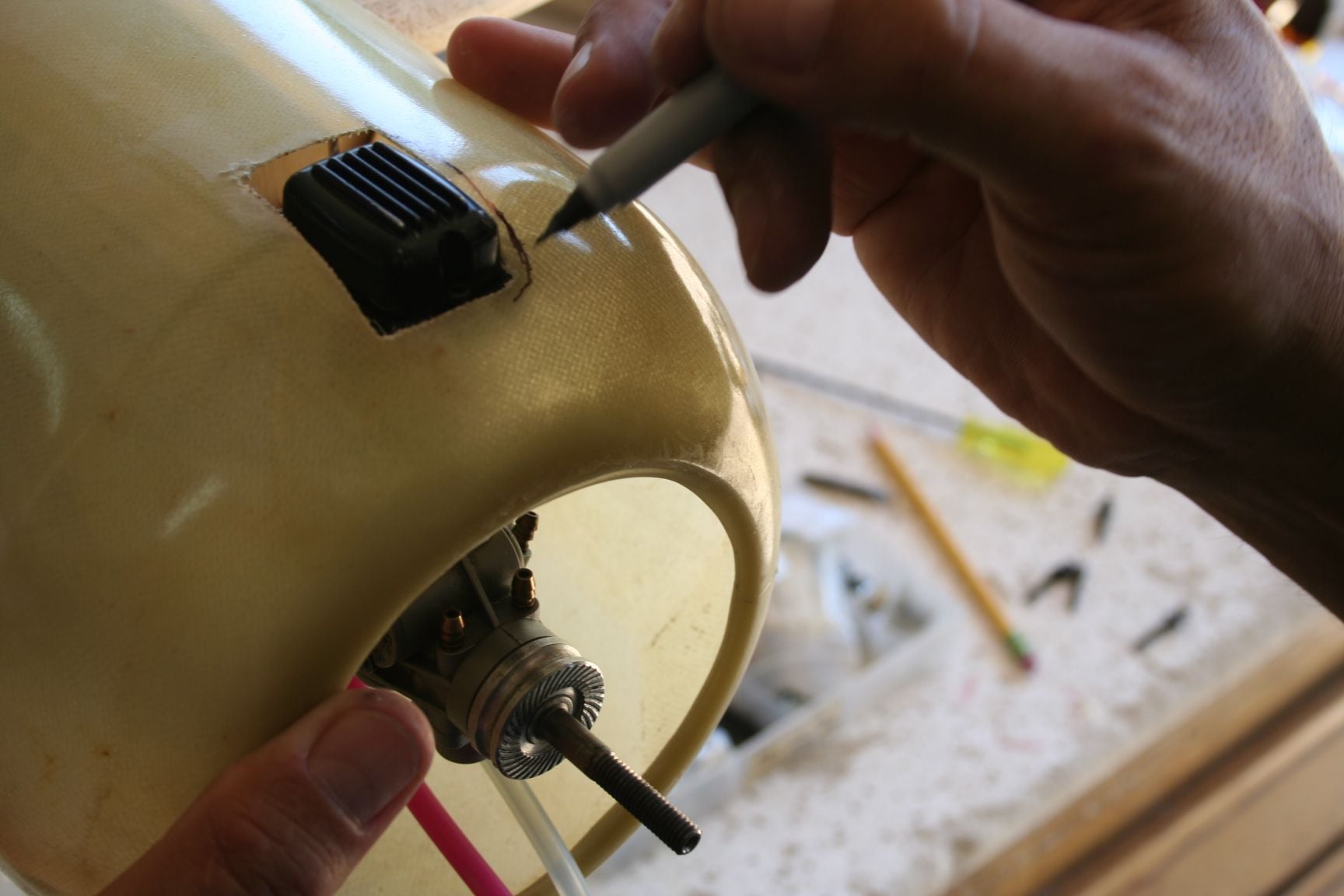
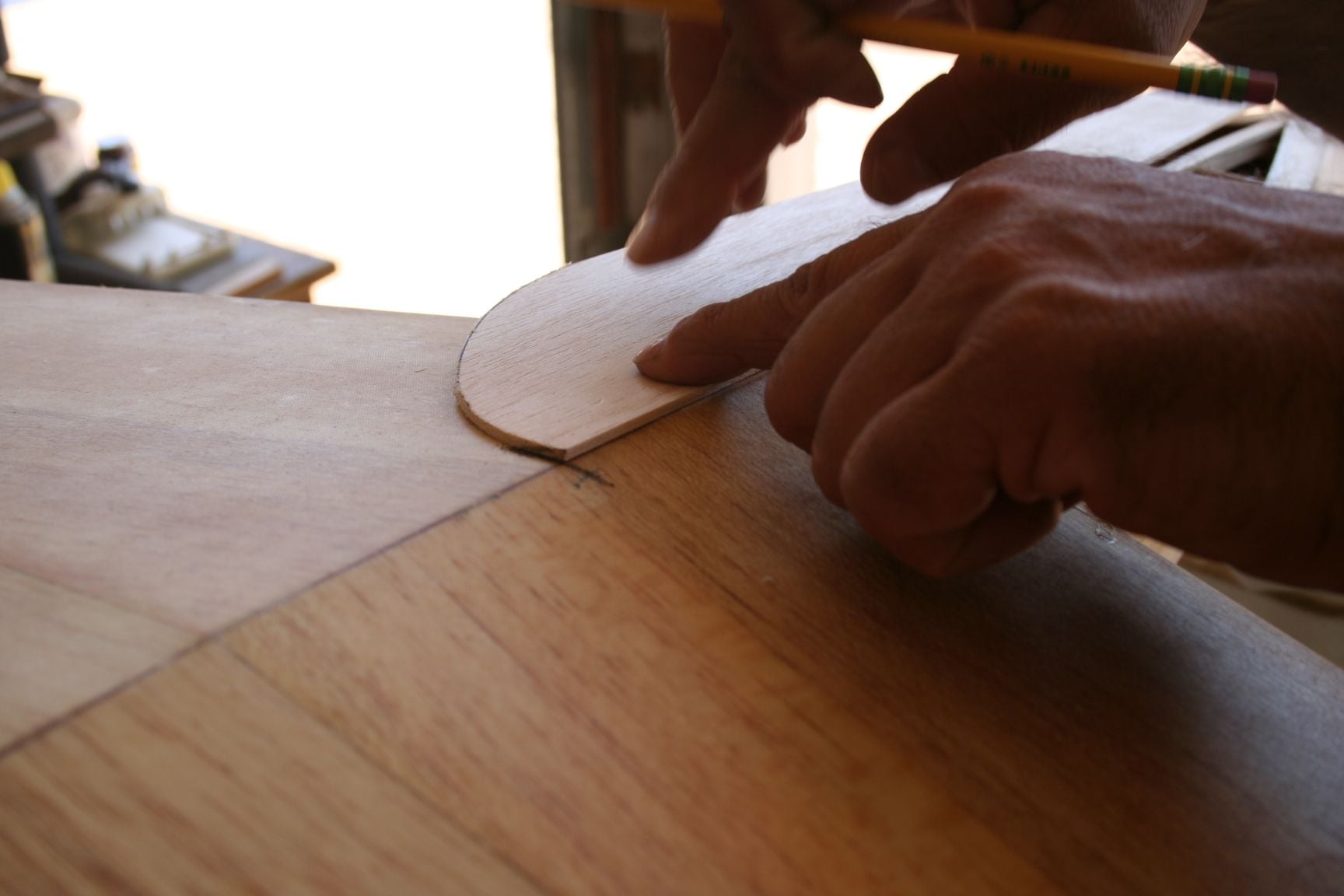
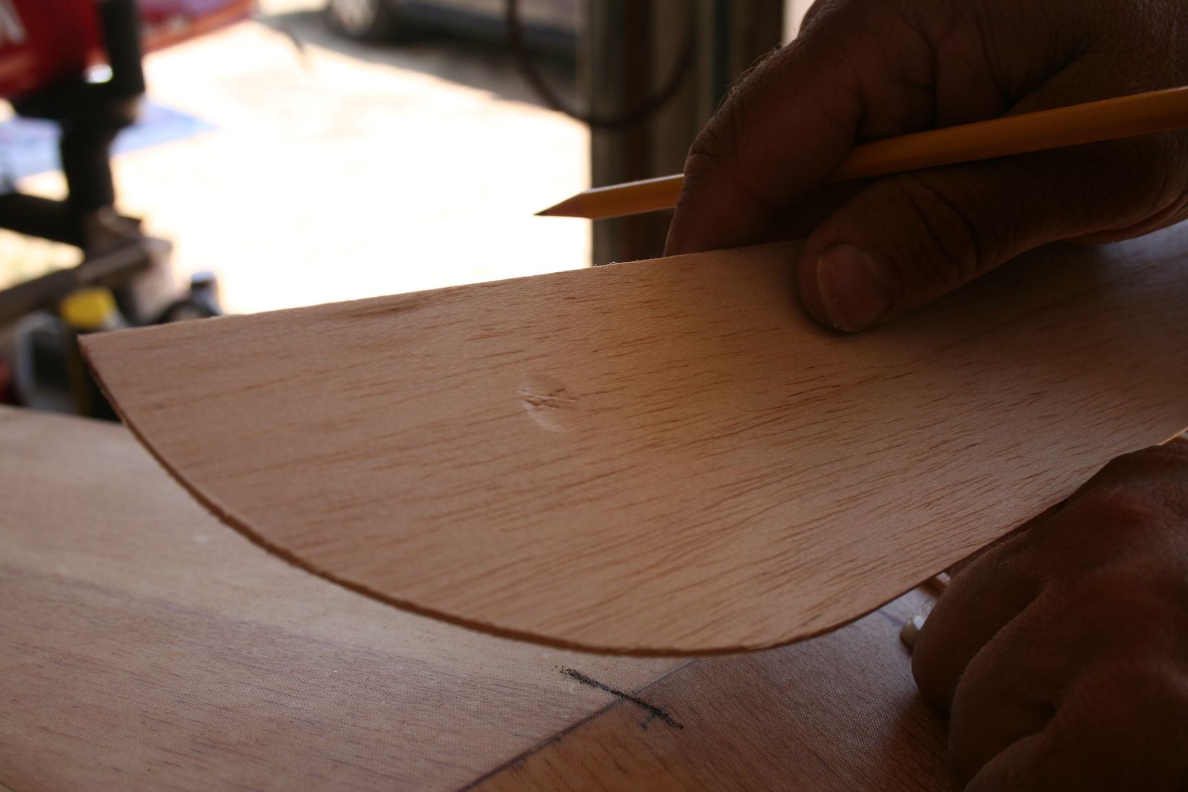
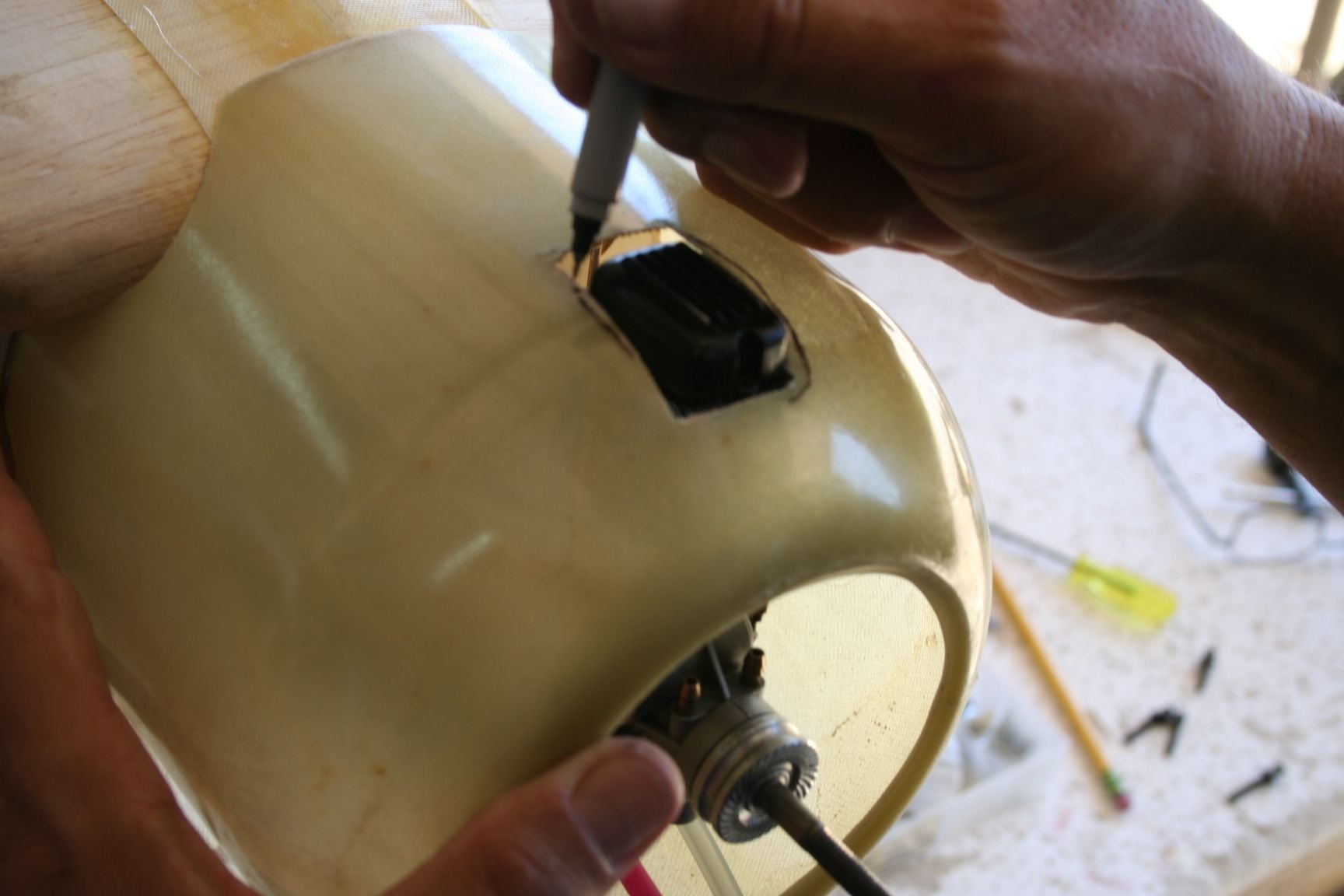
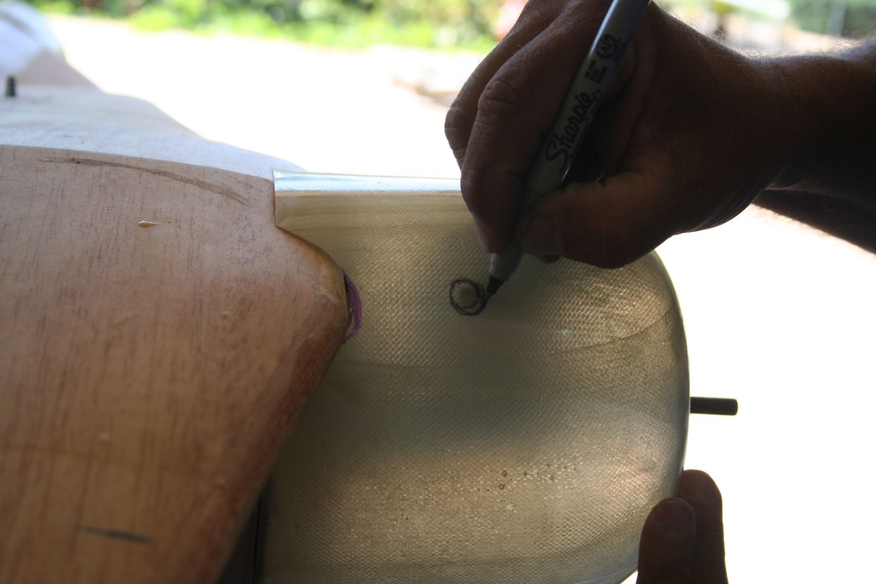
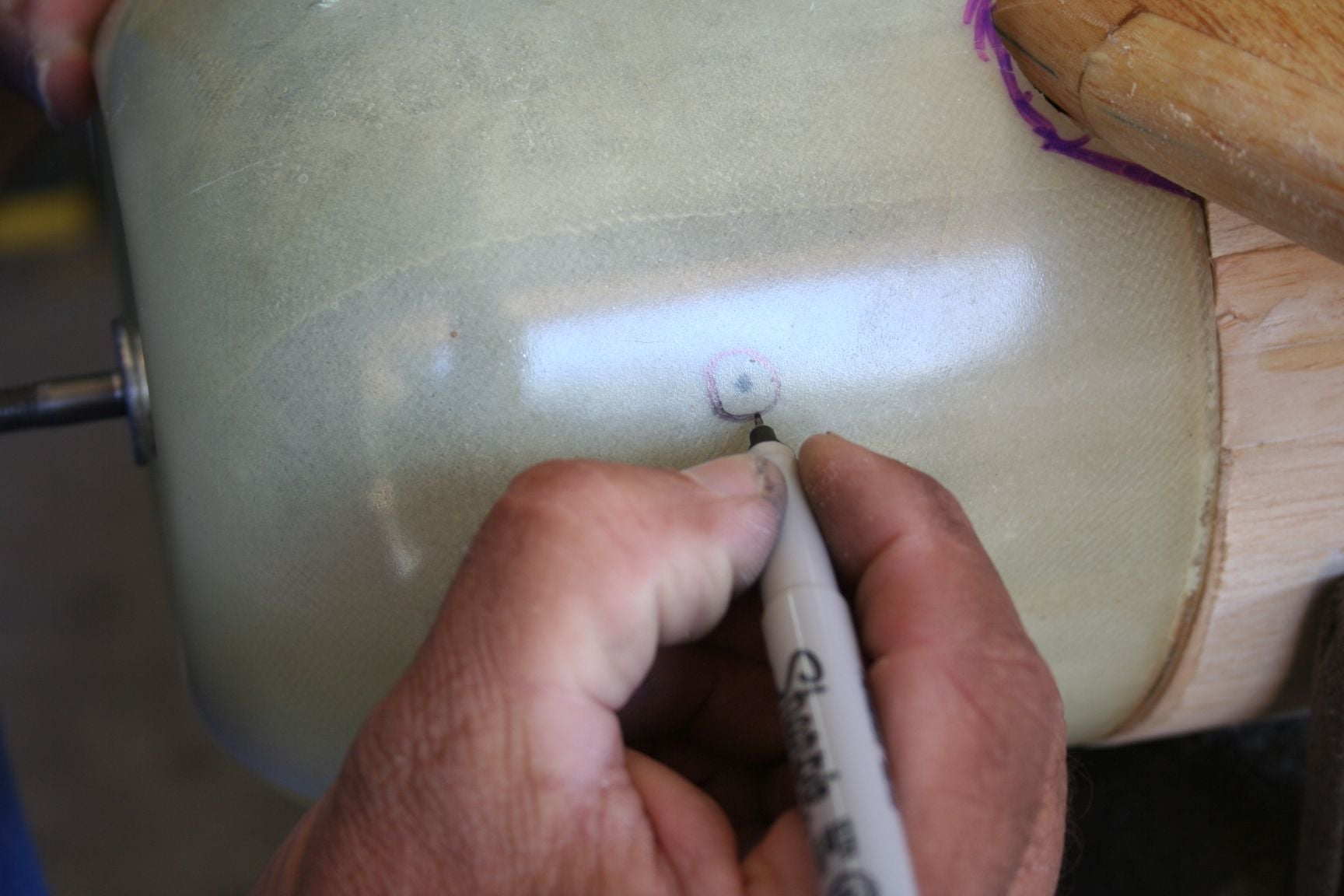
In this and the next picture, I am tracing where I desire to remove more material for curved and symmetrical amounts of clearance around the valve cover; as well as to round corners.
Sanding to my retraced lines and curves.
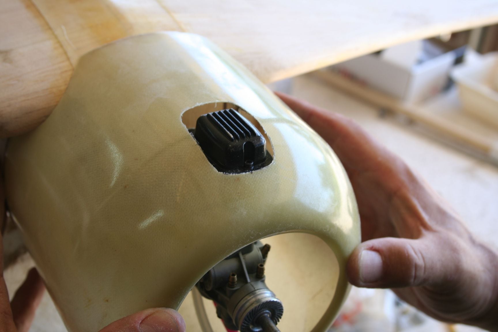
Second trial fit.

Still not fully satisfied. Outlining some more to be sanded away.
Initial trial fit after original opening was cut.
In this and the next picture, I am tracing where I desire to remove more material for curved and symmetrical amounts of clearance around the valve cover; as well as to round corners.
Sanding to my retraced lines and curves.
Second trial fit.
Still not fully satisfied. Outlining some more to be sanded away.
09-03-2020, 10:04 PM
#344
Thread Starter
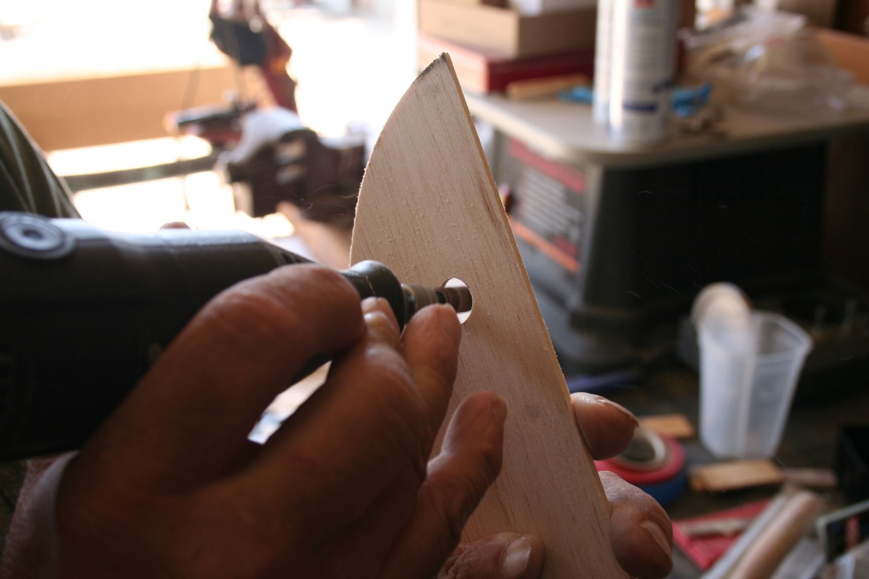
Tim does the same: (He actually did his first. But he went through the initial steps before I knew he was even starting on it, so I missed photographing his initial steps.)
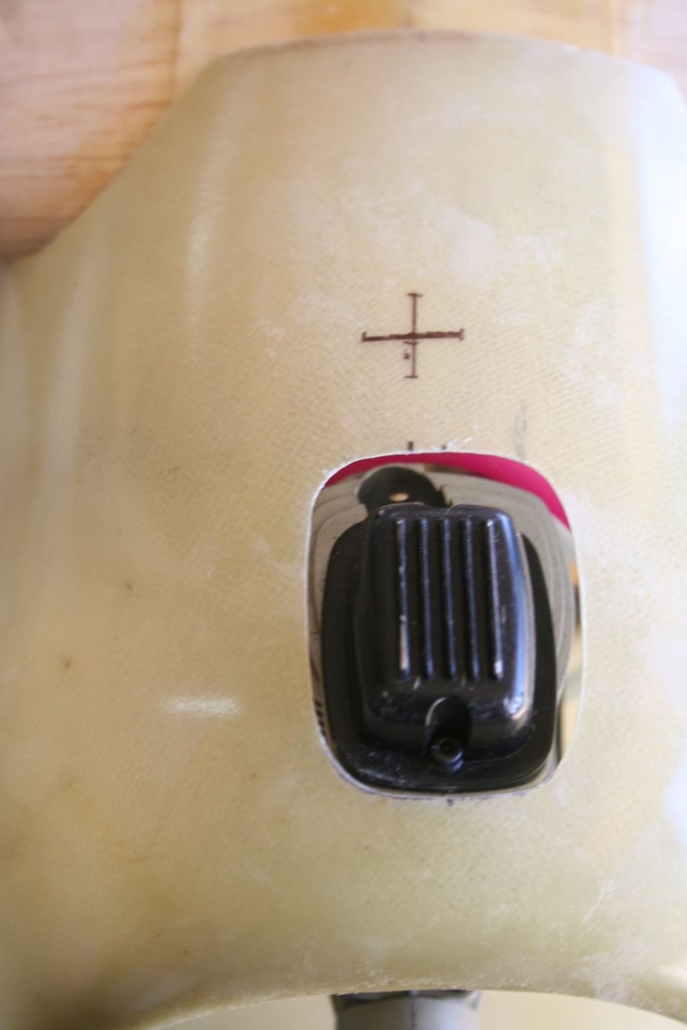
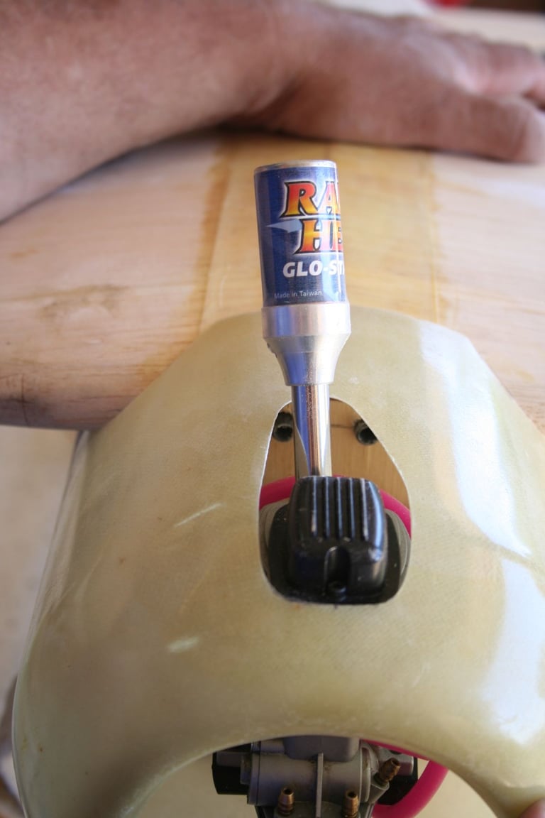
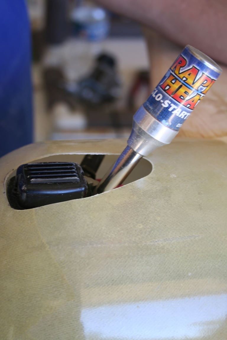
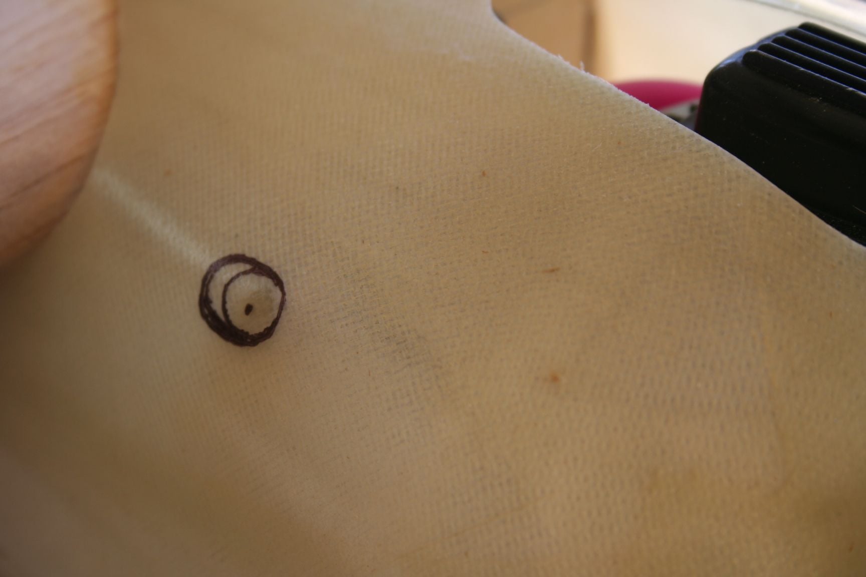
While we were are at it, we must also cut clearance for the glow igniter. On a YS engine, this is off-center, as well as slanted to the rear. I made alignment marks on the cowl, and used them to mark crosshairs for a clearance hole.
Next, I sand away the material in-between the two cut-outs and have a shape I am satisfied will be relatively user-friendly.
Fit is good, but the shape in the front, is still not symmetrical enough for me.
So again, I outline more to be sanded and shaped, better.
Last edited by Iron Dog; 09-03-2020 at 10:56 PM.
09-03-2020, 10:17 PM
#345
Thread Starter
Next, we mounted the stock exhaust pipe. Tim cuts a 2" piece of brass tubing, slightly smaller than the inside diameter of the exhaust pipe; and places it so that it will just clear the inside of the cowl.
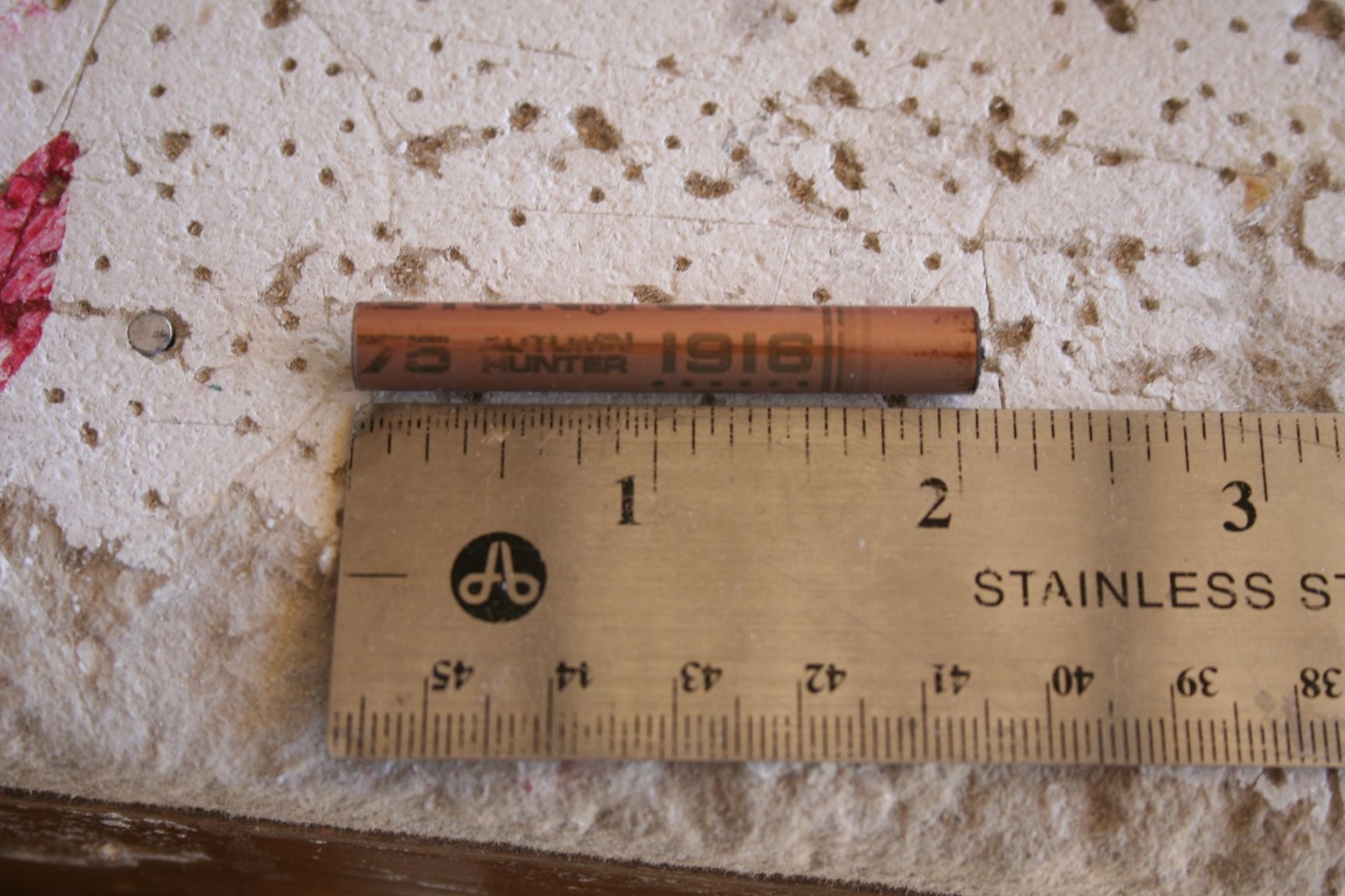

The exact position of the angled exhaust can now be seen and marked on the inside and/or outside of the cowl, and an accurate clearance hole is cut.
Tim begins by tracing the front of the opening on the inside of the cowl.
And, finishes on the outside of the cowl.
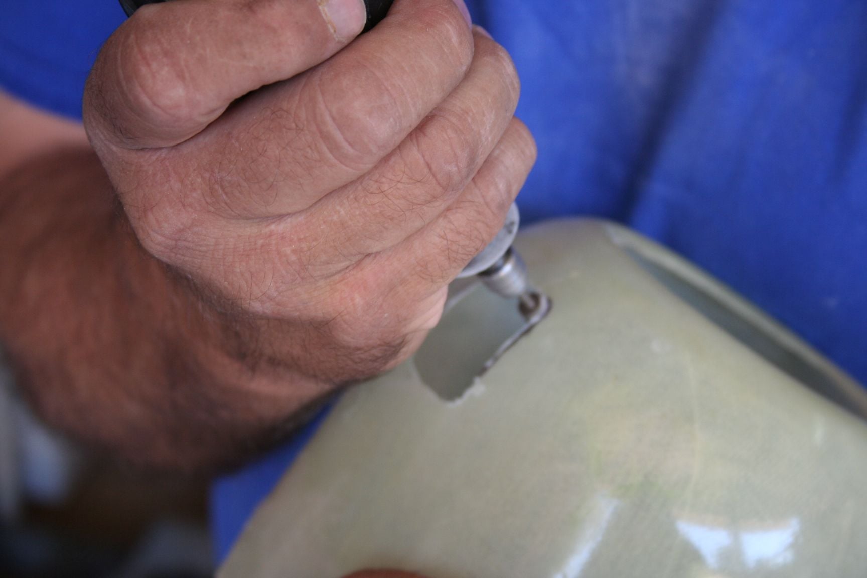
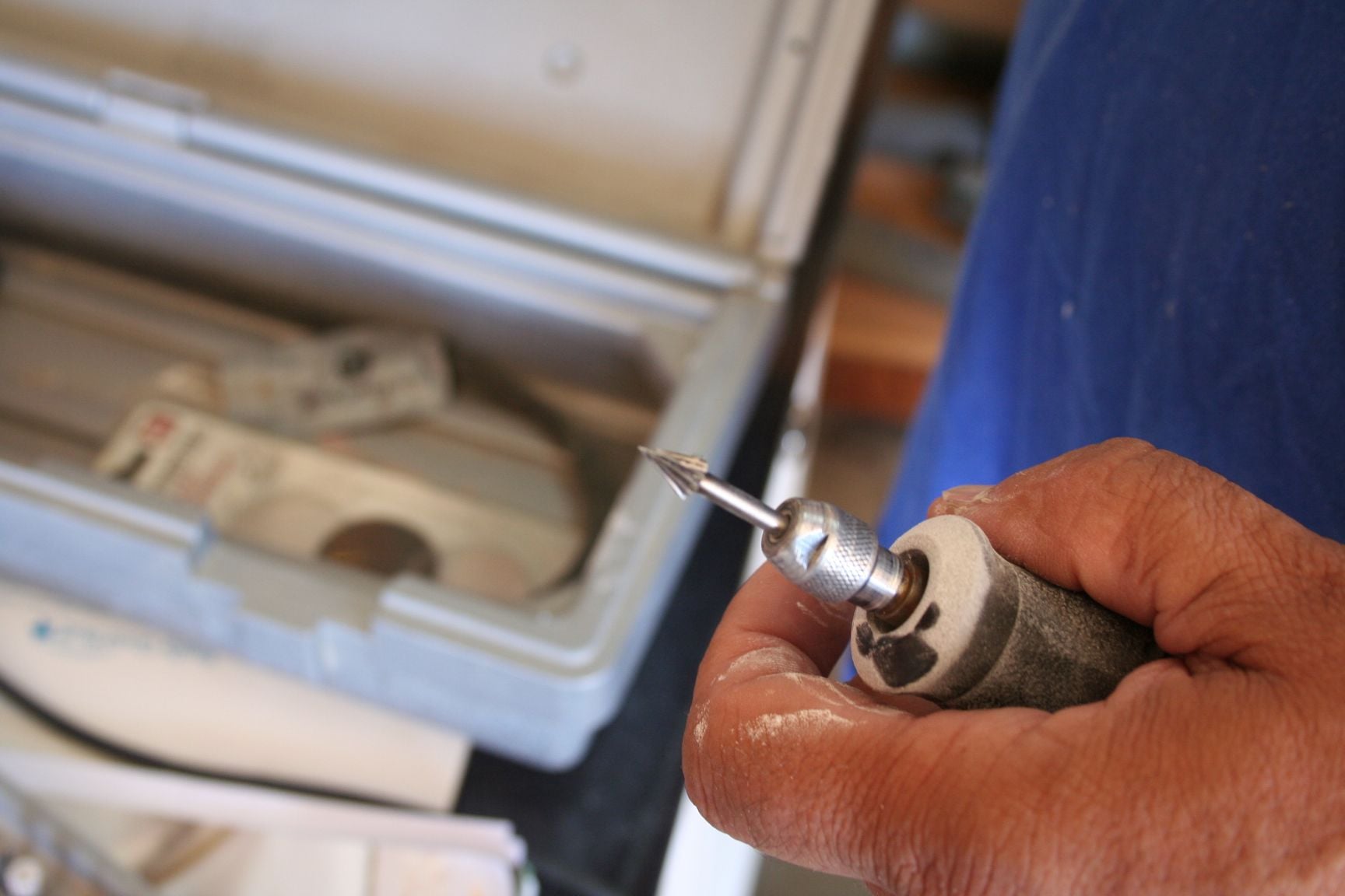
Dremel bits are used to cut the opening, and Tim trial-fits his cowl to ensure proper clearance. (Note that he is able to extend the brass tube through the center of his clearance hole.)
The exact position of the angled exhaust can now be seen and marked on the inside and/or outside of the cowl, and an accurate clearance hole is cut.
Tim begins by tracing the front of the opening on the inside of the cowl.
And, finishes on the outside of the cowl.
Dremel bits are used to cut the opening, and Tim trial-fits his cowl to ensure proper clearance. (Note that he is able to extend the brass tube through the center of his clearance hole.)
09-03-2020, 10:33 PM
#346
Thread Starter
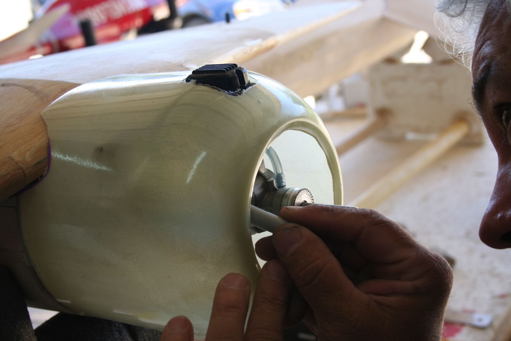
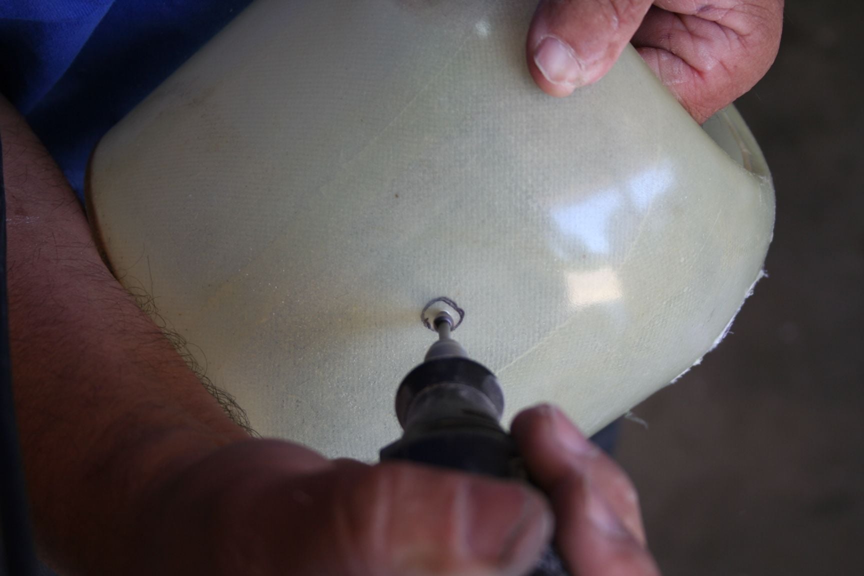
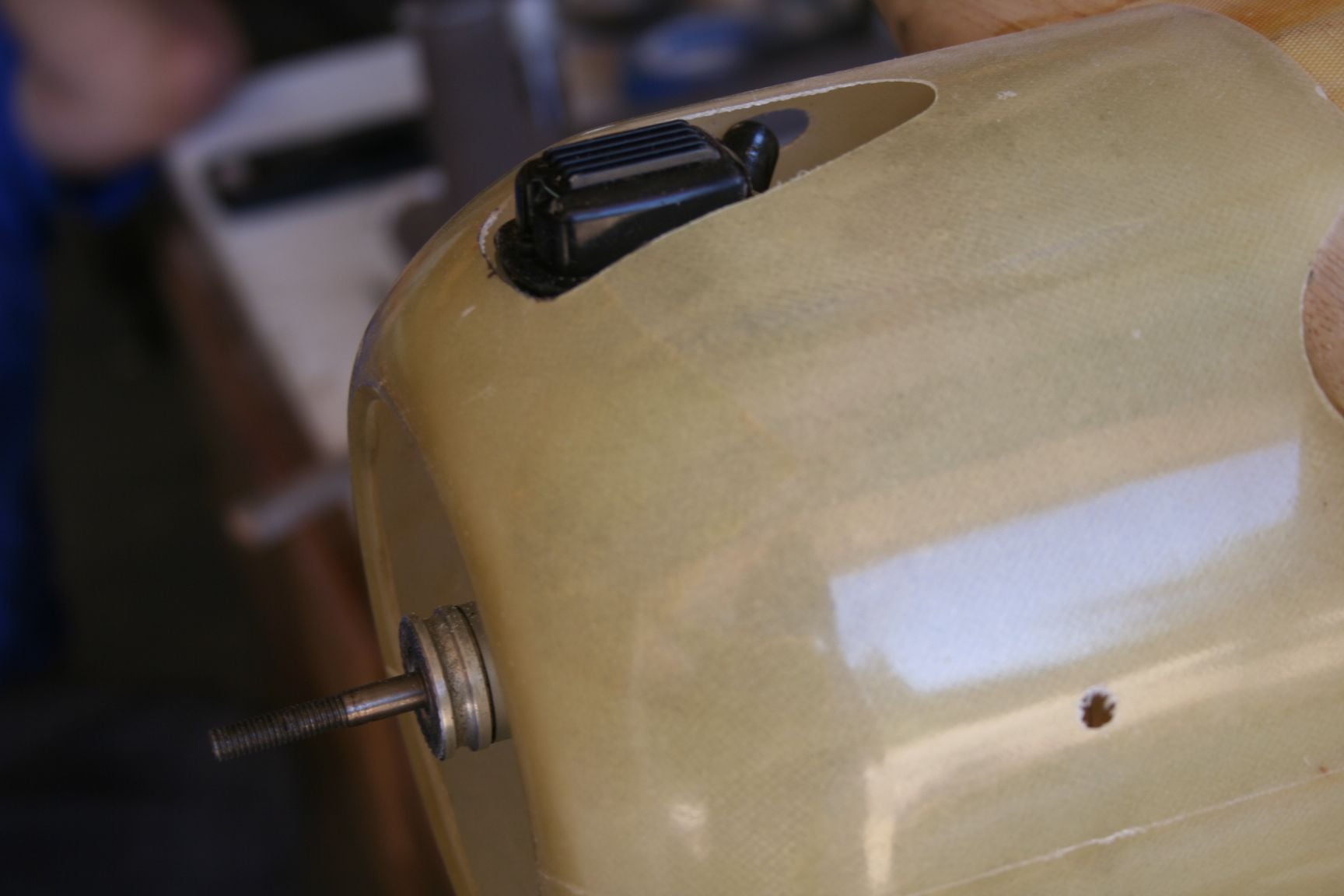
Now we need to cut a clearance hole for the needle valve.
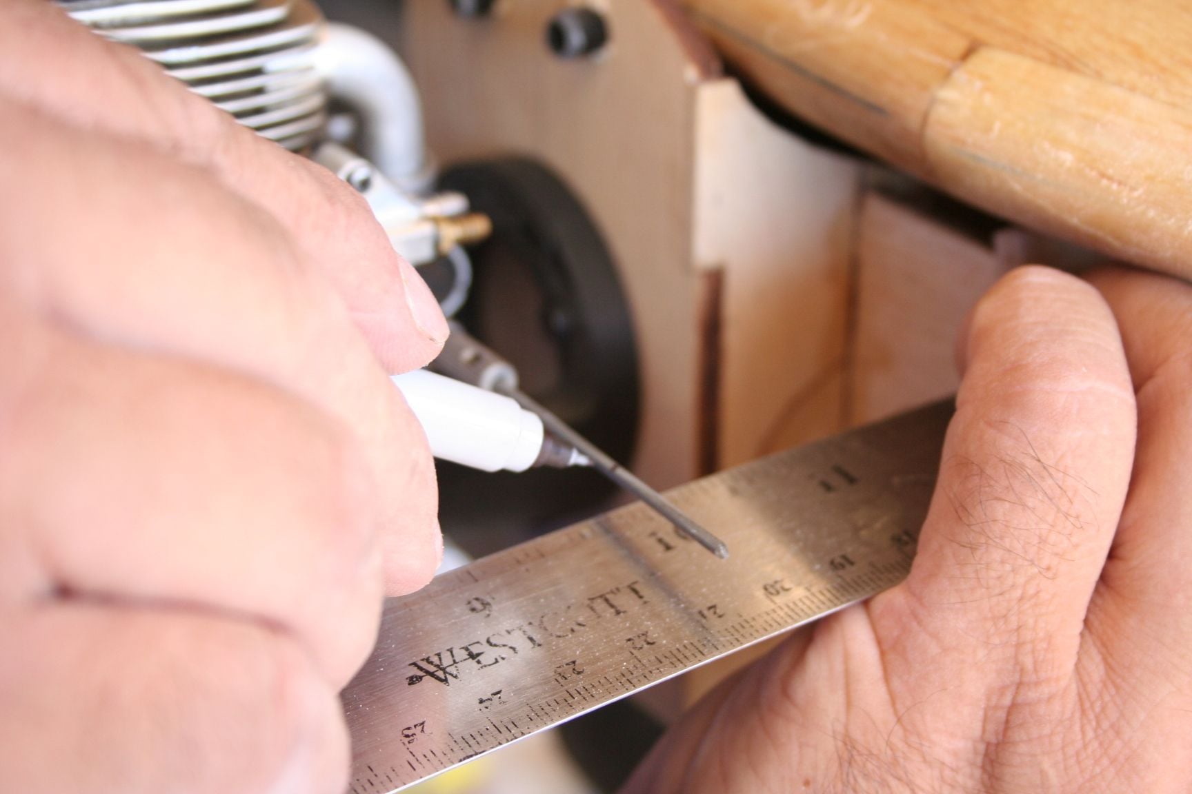
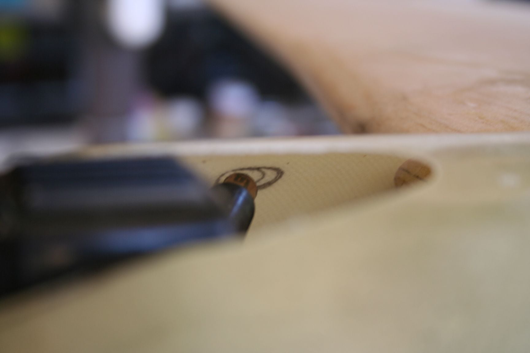
Music wire or pushrod is inserted into the needle valve. Tim aligned a straightedge/ruler to the outside of the fuse in order to mark where the cowl will come into contact with the wire. The wire was cut at this mark.
Tim then reinstalled his cowl, and marked where the needle-valve extension wire will exit the cowl.
 09-03-2020, 11:07 PM
#348
Thread Starter
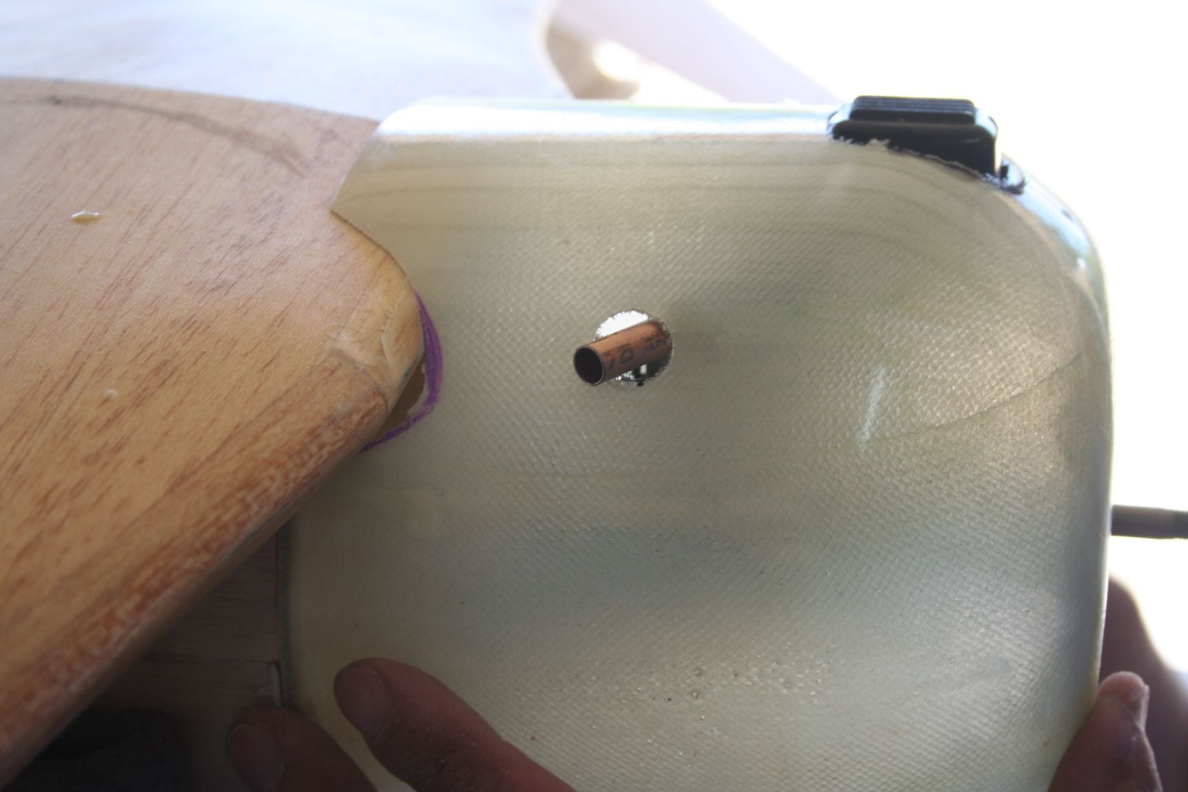
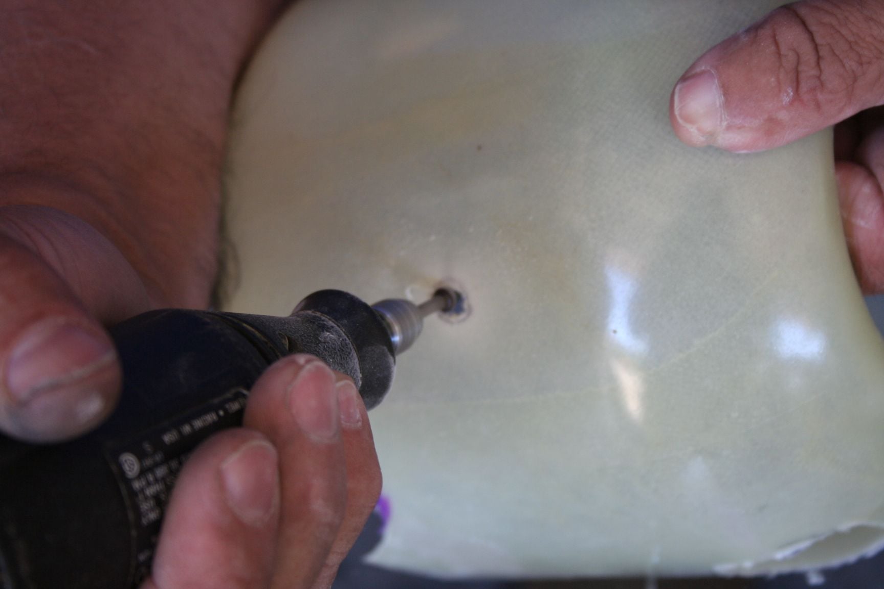
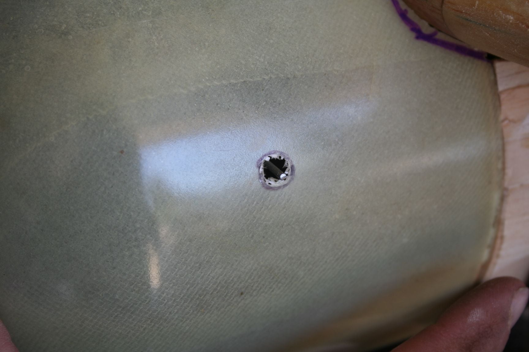
Now I mark and cut clearance holes for my exhaust and High-speed needle-valve extension in a similar manner to Tim.
Because of the angled exhaust and the curvature of the cowl, the clearance hole is actually oval-shaped, when completed.
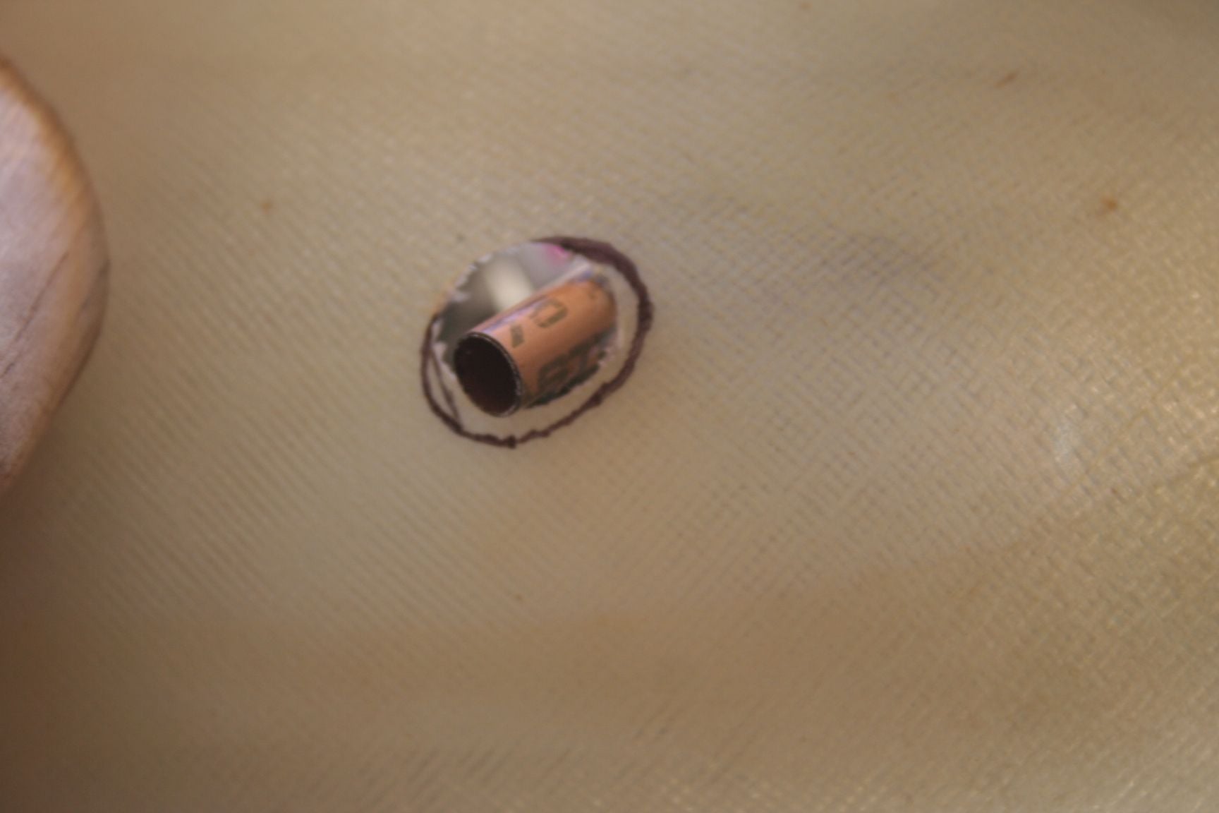
Both my exhaust and needle valve extension cut-outs are visible at this angle.
Because of the angled exhaust and the curvature of the cowl, the clearance hole is actually oval-shaped, when completed.
Both my exhaust and needle valve extension cut-outs are visible at this angle.