Spacewalker 2.2m wingspan
 08-16-2018, 08:53 AM
#1

Thread Starter
Hi,
I am posting to motivate my self to finish this plane, please say something if you think you can help to improve my building techniques as well as the plane construction it self.
The Spacewalker will be powered by NGH GF30, I am expecting a leisure scale sport flight. I think its around 25% scale ?
I got the plan from aerofred, however I redraw the formers, as well as the front part of the plane construction after seeing some of my ARFs. This is not my first scratch build, I recently finished a twin super sportster with two 0.25 engines, flew with almost no trim, crashed it after I stalled one engine during vertical U-turn, didnt have enough sky to recover.
Back to the Spacewalker, I also redraw the wing using DEVWING, it has helped me alot with some builds. I am including fowler flaps to the wing, hopefully it will help in landing on our short runway.
I will try to post more picture everytime I can finish something
The first 19 pictures are really not in order, i have worked on it for a few weeks now.
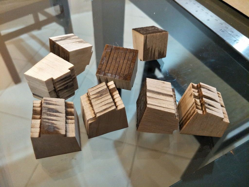
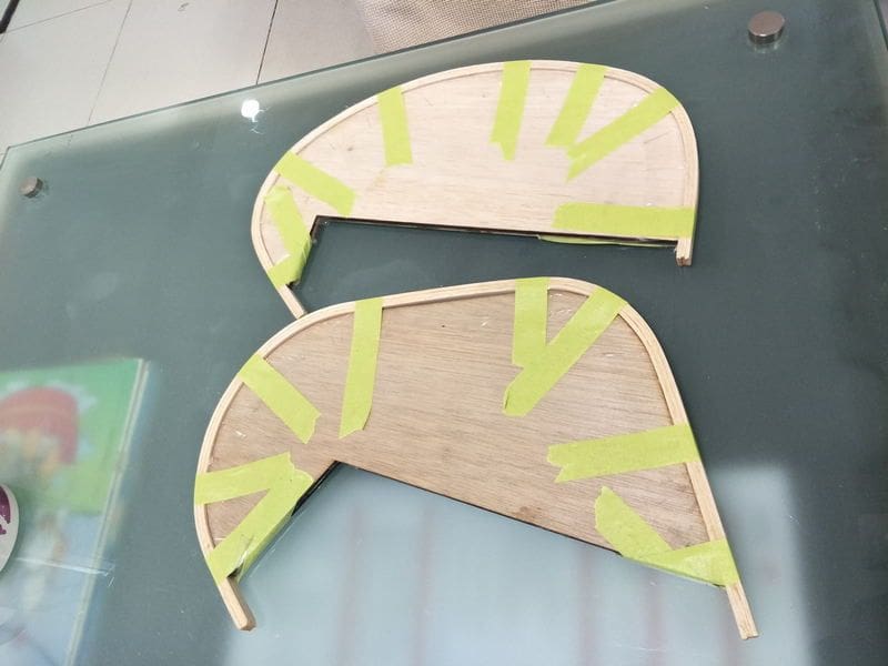
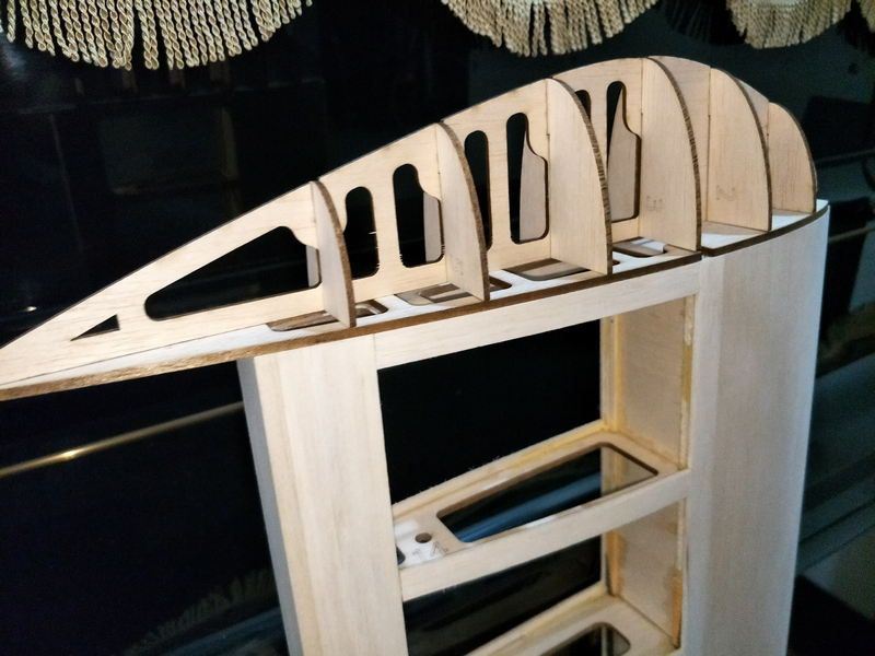
For the rib cap strips, I have always run the grain direction across the rib, just like the dbox sheeting.
However, this plane needs about 130mm cap strips, and I really hate to join the balsa sheets as its only 100mm wide. Say if I run the cap strips with grain direction from front to back (parallel to the rib), what disadvantage would I face?
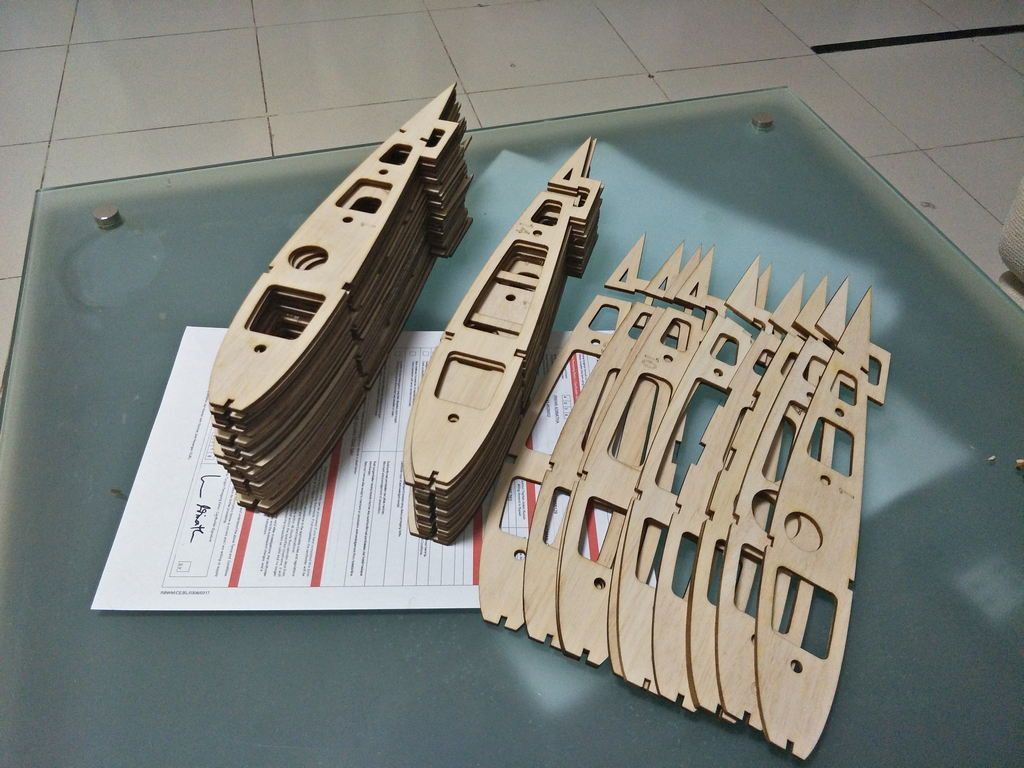
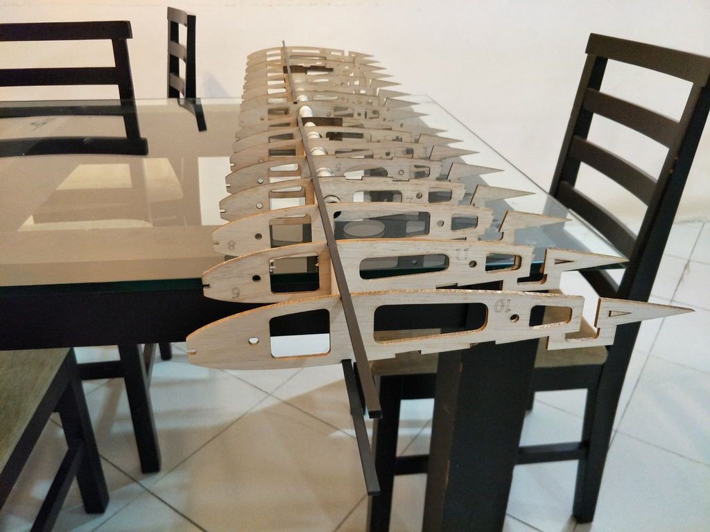
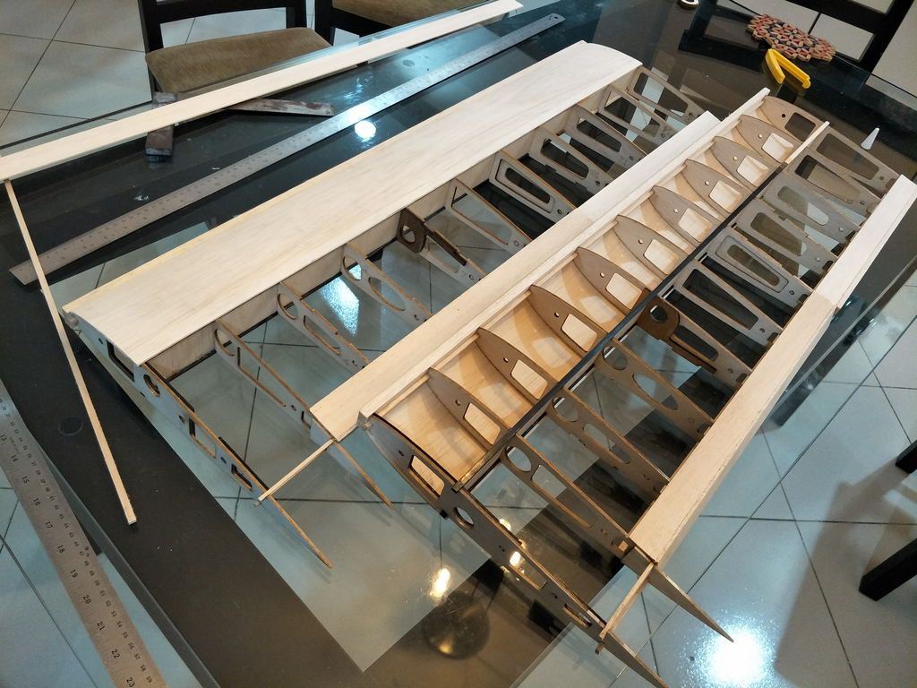
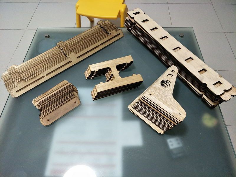
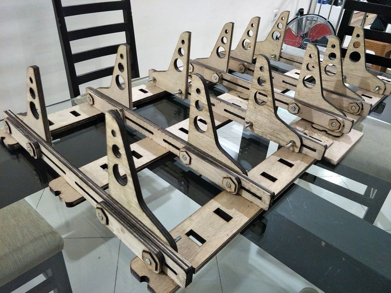
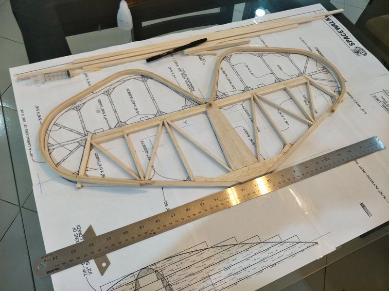
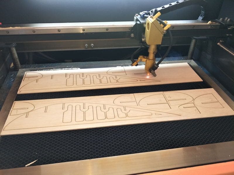
Cut two sets of ribs.
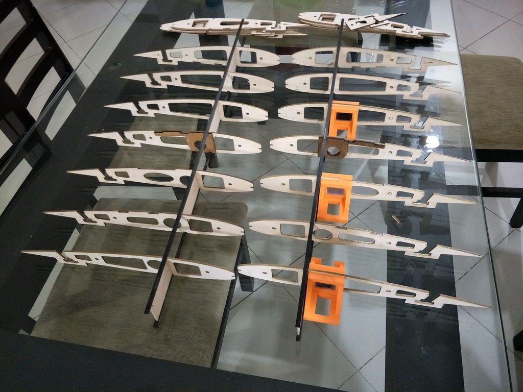
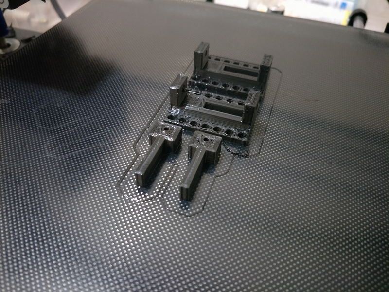
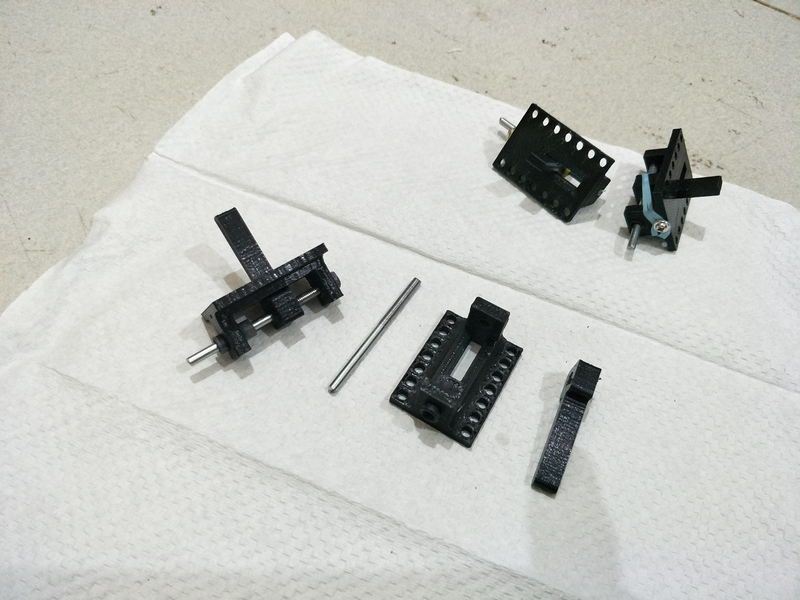
some tools 3d printed help with squaring the ribs, gotta build table with some steel.

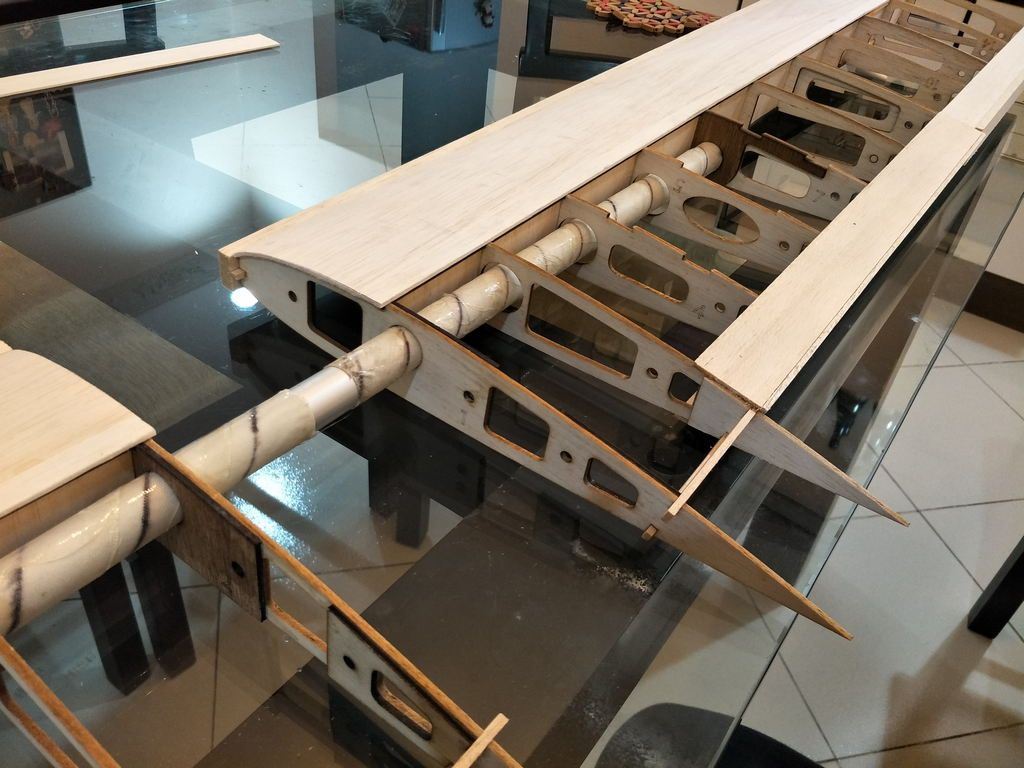
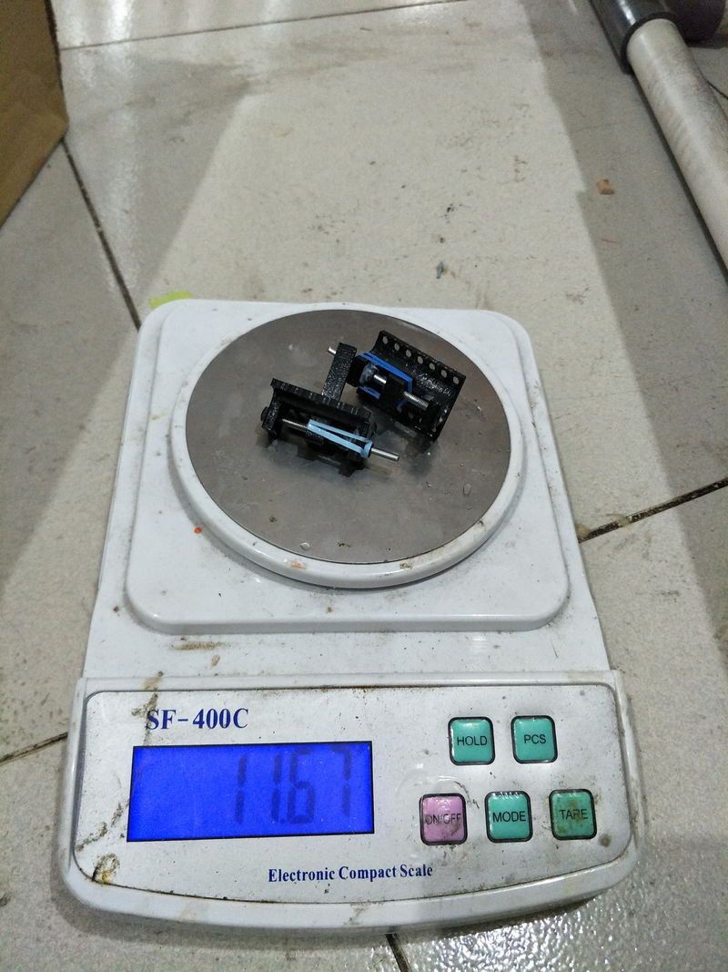
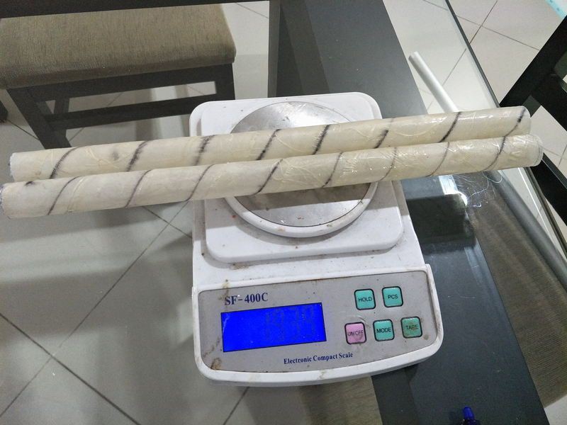
wing tube sleeve fits very well. Made from fiberglass and expoxy.
Test fit the tubes
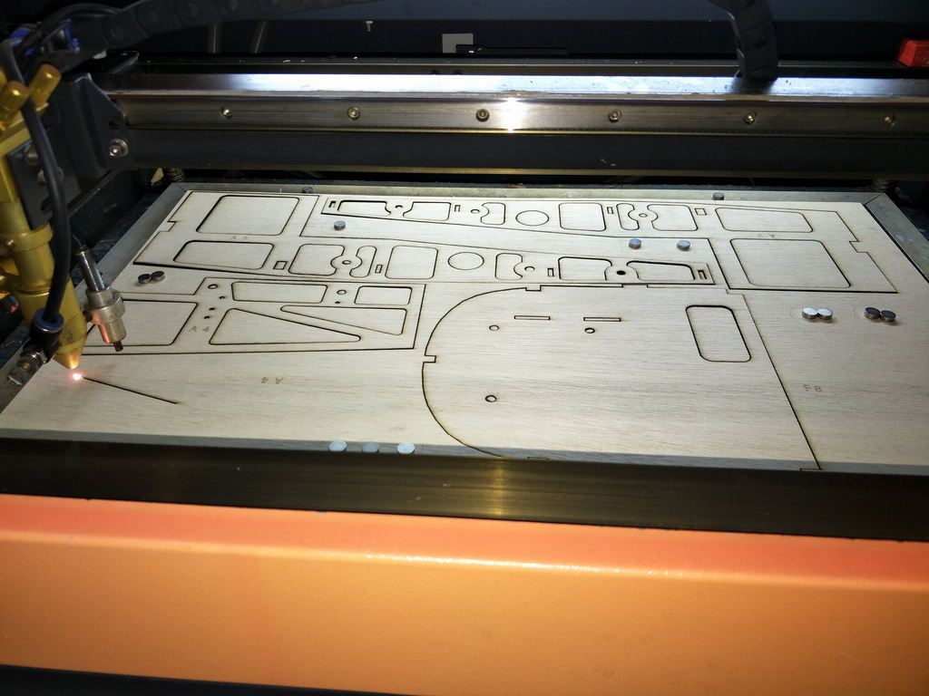
Cutting some formers and fuse sides. No light ply here.
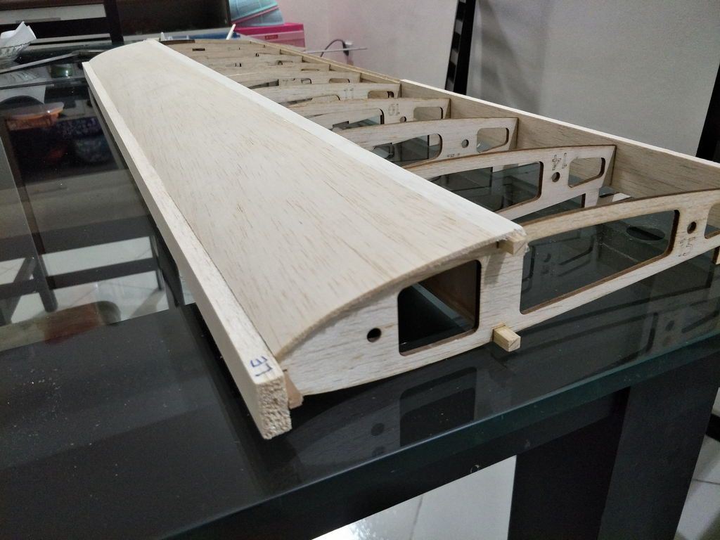
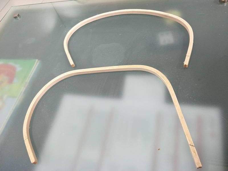
Leading edge glued.

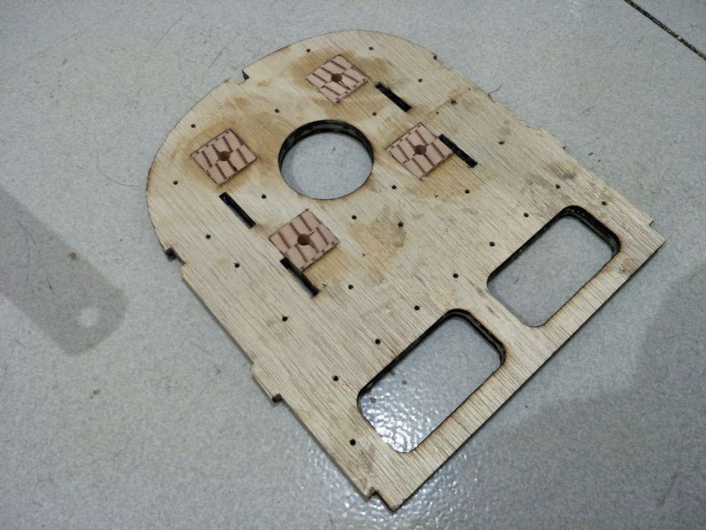
sandwiching the firewall with some carpenters glue.
Inserts for the engine mount hard point. Made from imported Birch (or so the seller said). I probably shall use harder wood, but this one is already harder than the ply. I glued them to the ply with some 90mins epoxy.
ailerons
ailerons and flaps withe sheetng, gotta glue some cap strips. I should have installed the 45 degree additional ribs of the flaps (wider ones).
Truing the sheets, then glued a bit more sheet to make up the width needed.
Glued it. With CA easy and fast.
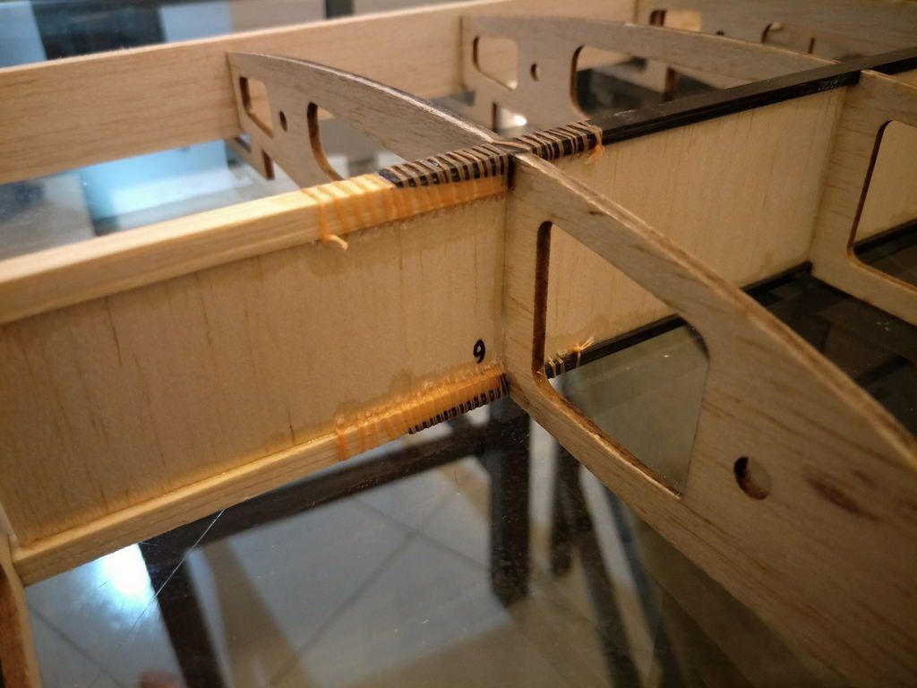
The length of halfspan is 900mm. I glued 3 pieces of 6mm widex1mm thick carbon fiber stick. Its only 750mm long, so I spliced it with pine I recover from used packaging material then I add some fishing line at the splice.
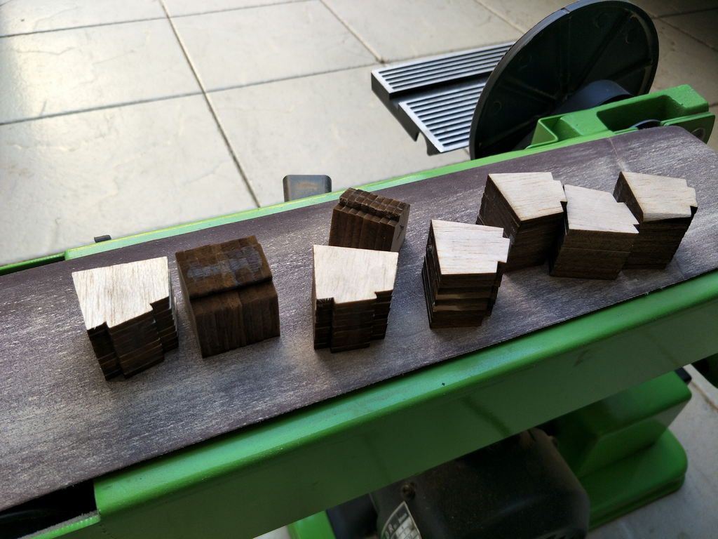
hinge mount point for the flaps made from used balsa sheets glued together, ready to be sanded
Sanded and fits ok.

glued with carpenters glue and tacked with CA, then I saturate some CA to wick. I might regret using balsa for the flap hinge with the plastic robart hinge. On my last build the whole right aileron came off !!! Somehow the hinge ripped off from the wood.
I am posting to motivate my self to finish this plane, please say something if you think you can help to improve my building techniques as well as the plane construction it self.
The Spacewalker will be powered by NGH GF30, I am expecting a leisure scale sport flight. I think its around 25% scale ?
I got the plan from aerofred, however I redraw the formers, as well as the front part of the plane construction after seeing some of my ARFs. This is not my first scratch build, I recently finished a twin super sportster with two 0.25 engines, flew with almost no trim, crashed it after I stalled one engine during vertical U-turn, didnt have enough sky to recover.
Back to the Spacewalker, I also redraw the wing using DEVWING, it has helped me alot with some builds. I am including fowler flaps to the wing, hopefully it will help in landing on our short runway.
I will try to post more picture everytime I can finish something
The first 19 pictures are really not in order, i have worked on it for a few weeks now.
For the rib cap strips, I have always run the grain direction across the rib, just like the dbox sheeting.
However, this plane needs about 130mm cap strips, and I really hate to join the balsa sheets as its only 100mm wide. Say if I run the cap strips with grain direction from front to back (parallel to the rib), what disadvantage would I face?
Cut two sets of ribs.
some tools 3d printed help with squaring the ribs, gotta build table with some steel.
wing tube sleeve fits very well. Made from fiberglass and expoxy.
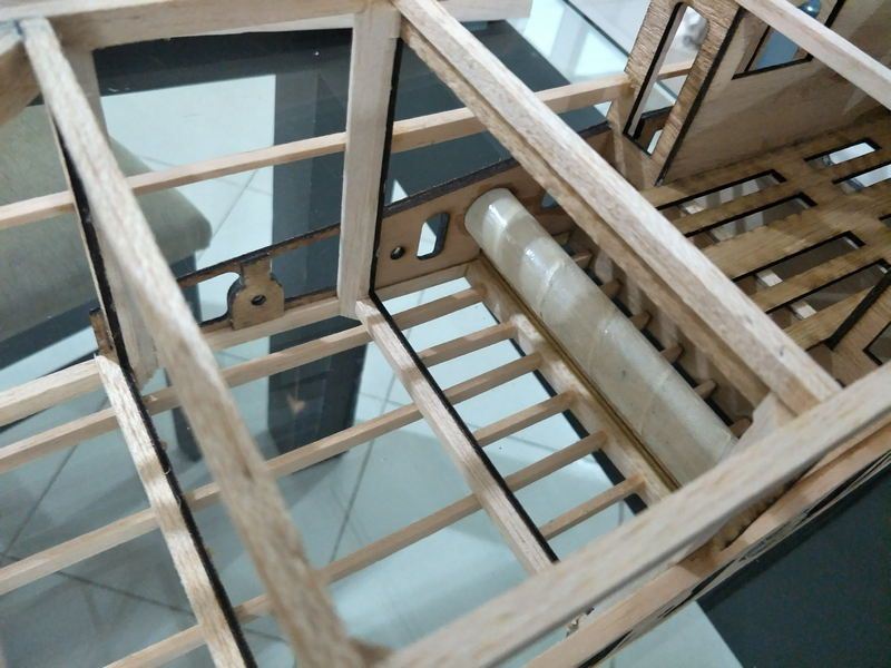
Test fit the tubes
Cutting some formers and fuse sides. No light ply here.
Leading edge glued.
sandwiching the firewall with some carpenters glue.
Inserts for the engine mount hard point. Made from imported Birch (or so the seller said). I probably shall use harder wood, but this one is already harder than the ply. I glued them to the ply with some 90mins epoxy.
ailerons
ailerons and flaps withe sheetng, gotta glue some cap strips. I should have installed the 45 degree additional ribs of the flaps (wider ones).
Truing the sheets, then glued a bit more sheet to make up the width needed.
Glued it. With CA easy and fast.
The length of halfspan is 900mm. I glued 3 pieces of 6mm widex1mm thick carbon fiber stick. Its only 750mm long, so I spliced it with pine I recover from used packaging material then I add some fishing line at the splice.
hinge mount point for the flaps made from used balsa sheets glued together, ready to be sanded
Sanded and fits ok.
glued with carpenters glue and tacked with CA, then I saturate some CA to wick. I might regret using balsa for the flap hinge with the plastic robart hinge. On my last build the whole right aileron came off !!! Somehow the hinge ripped off from the wood.
 08-21-2018, 07:09 AM
#2
Thread Starter
4 Days passed and not much going on.
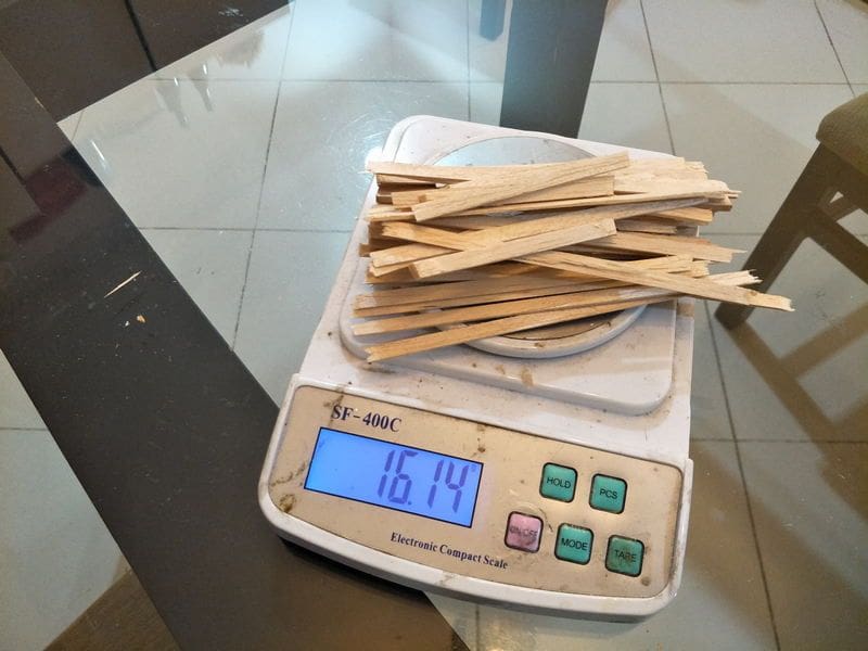
I managed to cut some cap strips, some hard balsa stick for the fuse truss construction, drill holes on the firewall so I can soak it with CA later on, break in the engine, made some right angle tools and install the magnets, tacked half of the fuse formers.
In this coming few days I will be busy with the new ARF I bought on a sale. Its seagul Sea Fury. Should be fun with new CRRC PRO GP22R engine. I was going to put an ASP FS90, however, nitro fuel has been diffcult to get lately, not to mention super expensive.
Next steps are, installing cap strips, testing the servo mounts on the wing, splicing the longerons for the fuse, making some Glass fiber tubes.
I need to figure out servo placement.I might have to cut F4 or F5 top part of the formers for easy access.
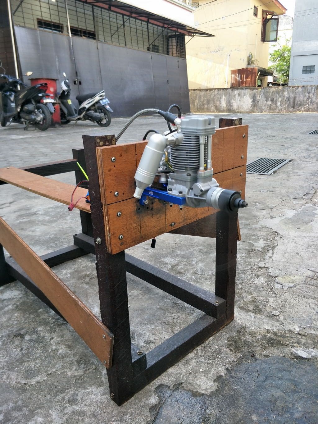
runs quite well. I need to work with the needles.
small holes so I can soak the ply with CA later

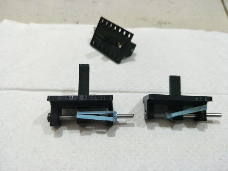
Some right angle tools I create and printed to suit the magnets
eyeball square.

weigh abou 180 grams.
I managed to cut some cap strips, some hard balsa stick for the fuse truss construction, drill holes on the firewall so I can soak it with CA later on, break in the engine, made some right angle tools and install the magnets, tacked half of the fuse formers.
In this coming few days I will be busy with the new ARF I bought on a sale. Its seagul Sea Fury. Should be fun with new CRRC PRO GP22R engine. I was going to put an ASP FS90, however, nitro fuel has been diffcult to get lately, not to mention super expensive.
Next steps are, installing cap strips, testing the servo mounts on the wing, splicing the longerons for the fuse, making some Glass fiber tubes.
I need to figure out servo placement.I might have to cut F4 or F5 top part of the formers for easy access.
runs quite well. I need to work with the needles.
small holes so I can soak the ply with CA later
Some right angle tools I create and printed to suit the magnets
eyeball square.
weigh abou 180 grams.
08-22-2018, 07:48 PM
#3
Thread Starter
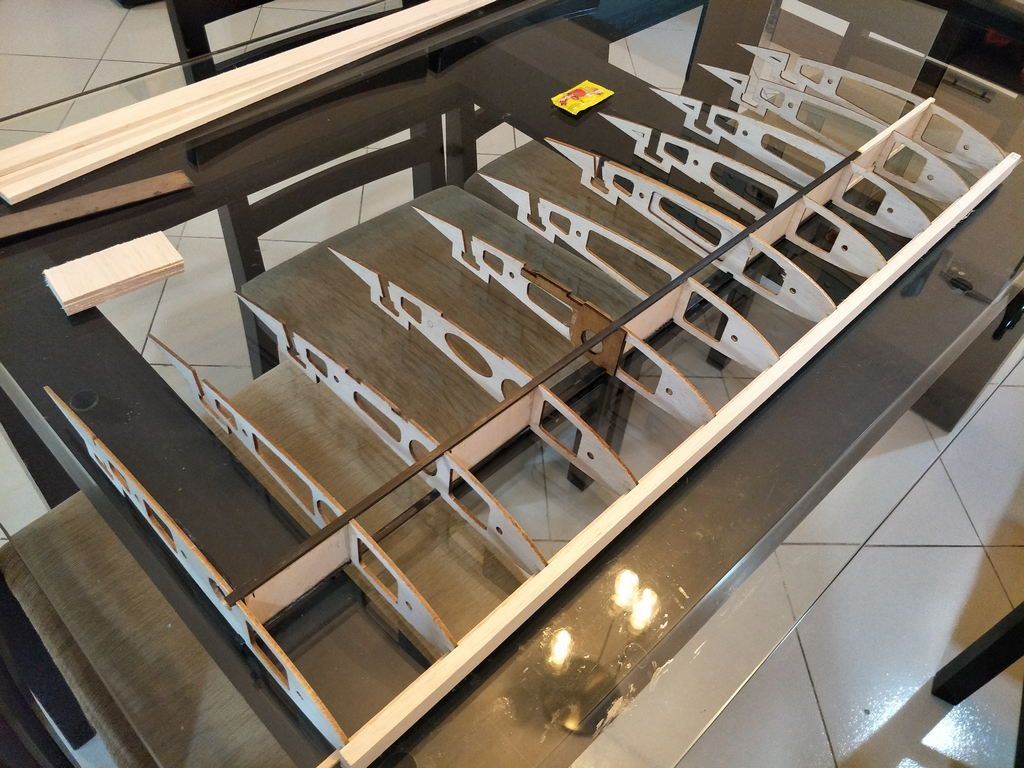
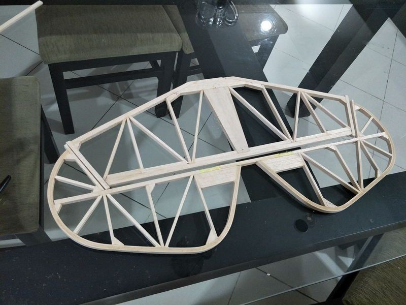
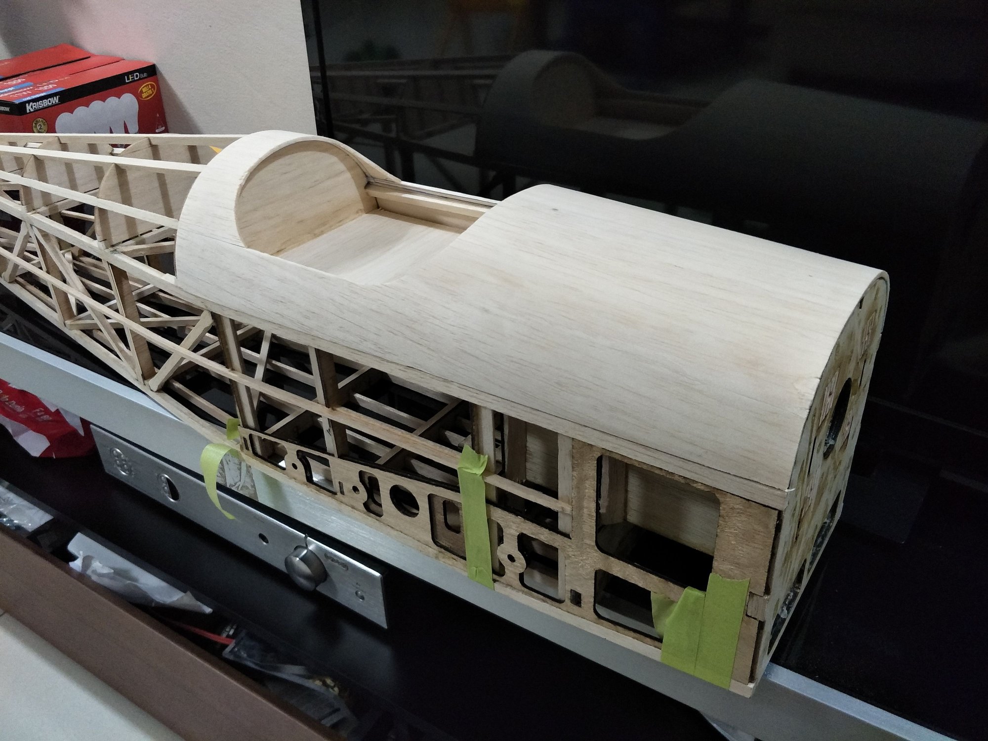
Made a little progress today building the fuse.
Cant decide if I want to keep the ply formers after the wing. I will have to reinforce with balsa sticks anyway. However, I cant find a way yet to align the tail properly without the ply formers.
I am thinking to use the formers as the momentary jig and remove them after I glue the truss structure,
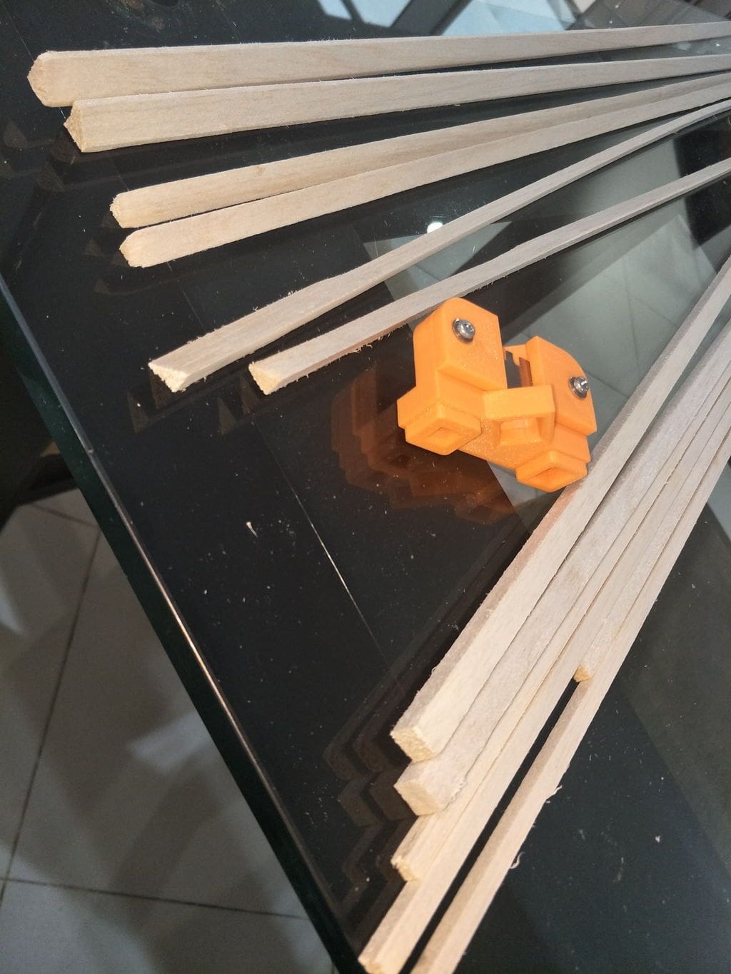
Cut some triangle stock with 3d printed tools
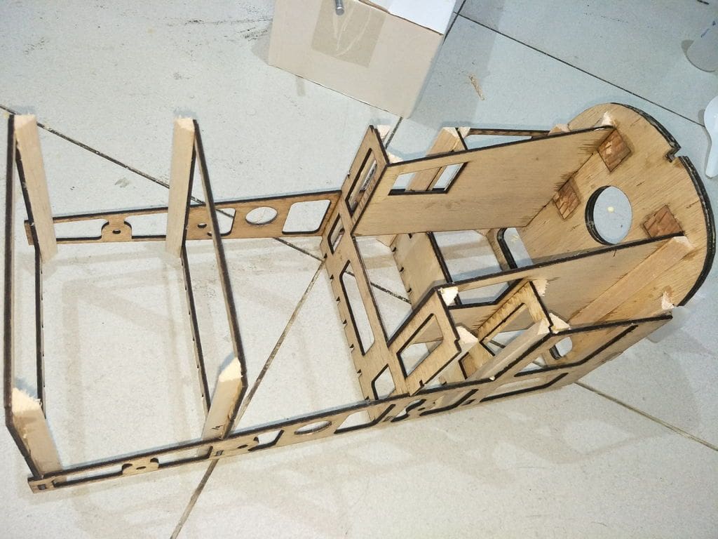
i fill the seams of the join with some epoxy so the plys will soak in, it was just tacked using CA. Then I glued the striangle stock with carperters glue and tack it with CA.
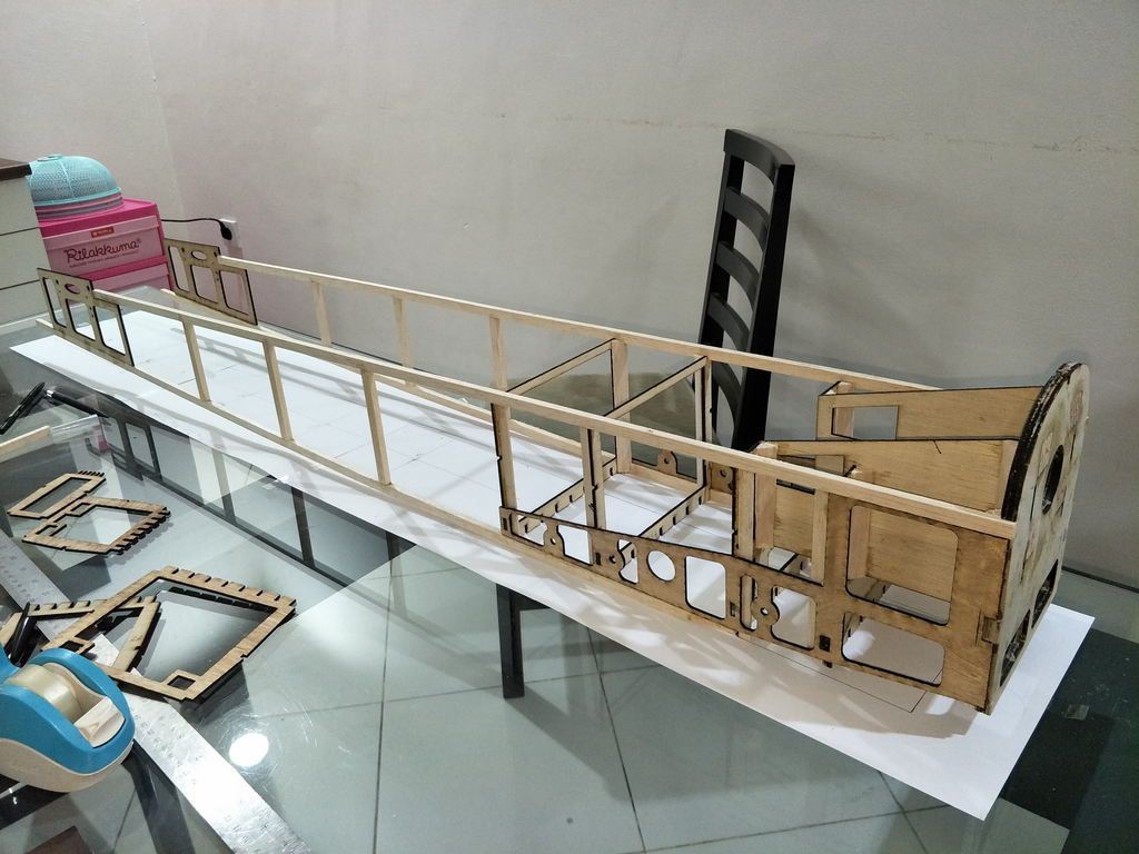
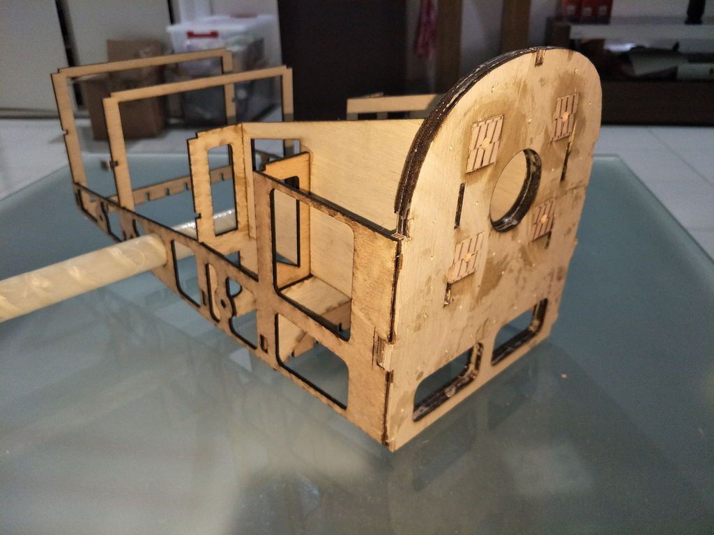
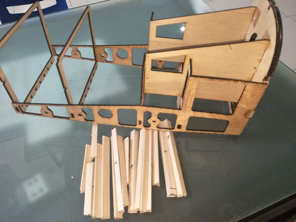
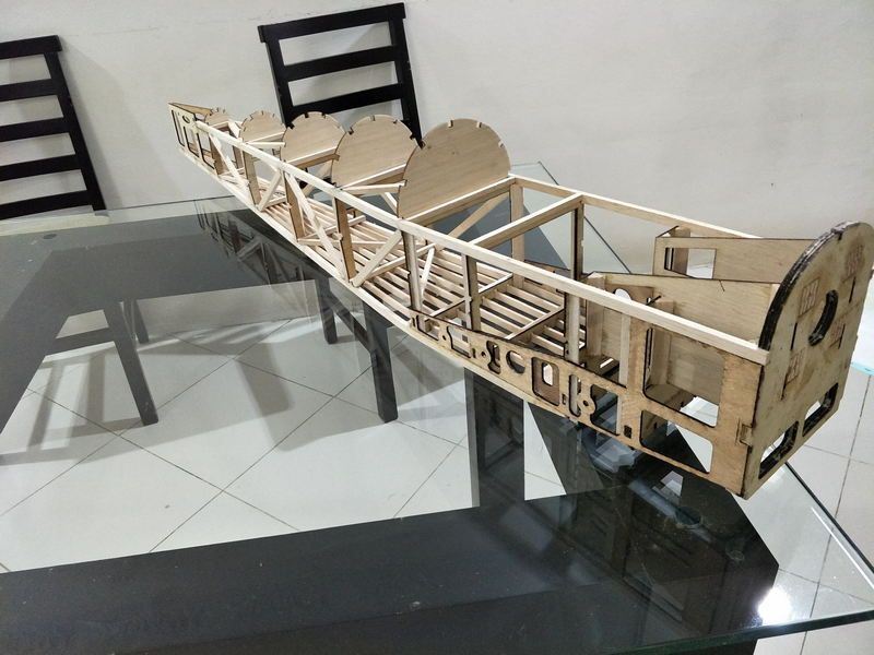
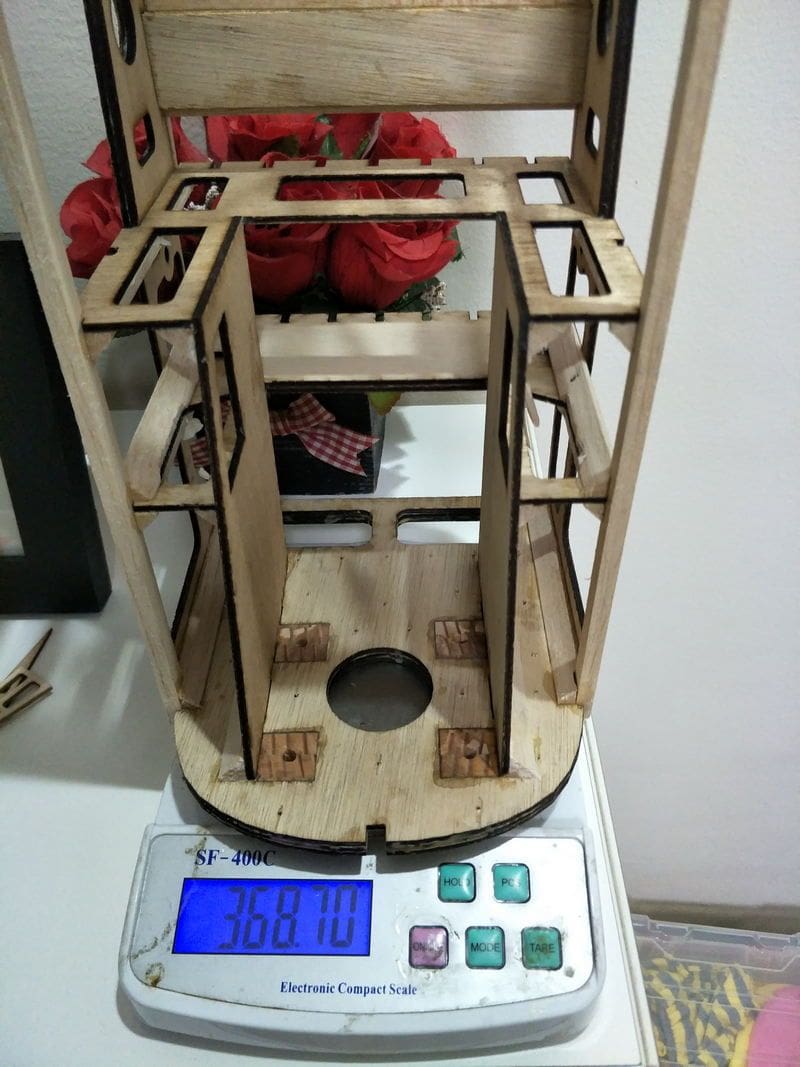
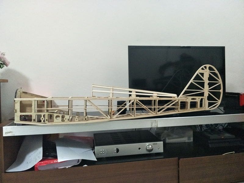
Some progress today. I am now thinking of best way to align the tail without proper tools The fuse now weight around 280 grams. The front part is quite sturdy and stiff.
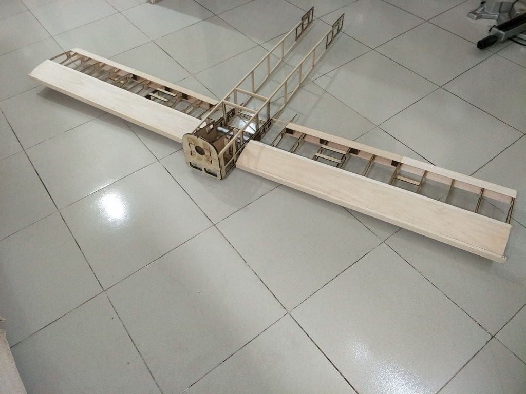
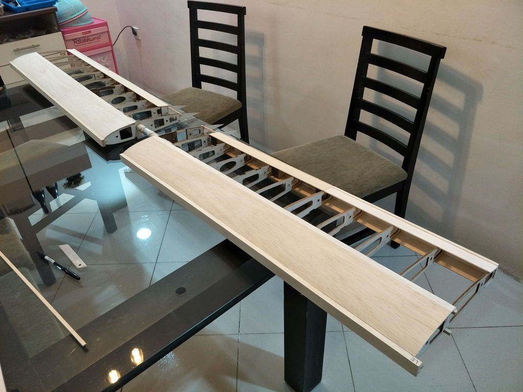
Test fit with the wing. Its quite big but small enough for easy transport.
Cant decide if I want to keep the ply formers after the wing. I will have to reinforce with balsa sticks anyway. However, I cant find a way yet to align the tail properly without the ply formers.
I am thinking to use the formers as the momentary jig and remove them after I glue the truss structure,
Cut some triangle stock with 3d printed tools
i fill the seams of the join with some epoxy so the plys will soak in, it was just tacked using CA. Then I glued the striangle stock with carperters glue and tack it with CA.
Some progress today. I am now thinking of best way to align the tail without proper tools
The fuse now weight around 280 grams. The front part is quite sturdy and stiff.Test fit with the wing. Its quite big but small enough for easy transport.
08-24-2018, 05:21 AM
#4
Thread Starter
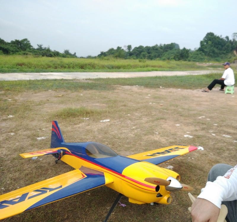
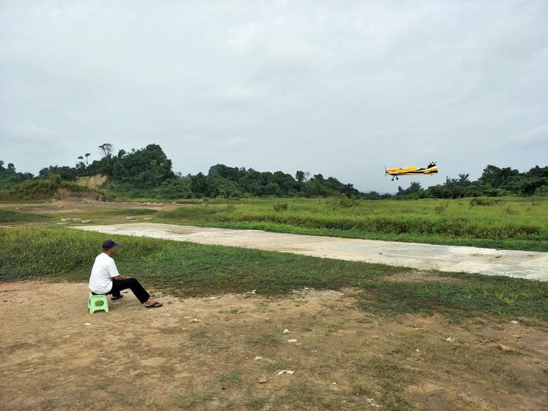
last night a friend called and ask me to fly with him this morning, which I did, and I am grateful for that, the weather was very nice. He flew for 10minutes x 4 and I did 2x10 minutes flight and had to stop since the covering trim got pulled off.
The MSXR is mine, had I been patient enough to wait for the shorter stud, the extra holes at the front of the cowl could have been prevented The twin RCGF 40cc is super fun to run on the plane.
The other plane is SLICK with DLE 30.
got home after work, I installed some silicone tubing on the H and L needle to help my screw driver stick on it while tuning, which took building time away.
I only managed to install the wing tube sock reinforcement on the fuse, as well as the rear main gear mount. I had to cut new mount since the first cut was 6mm shorter !
Its a bit soft and springy right now, I might have to reinforce it with some spruce stick.
The MSXR is mine, had I been patient enough to wait for the shorter stud, the extra holes at the front of the cowl could have been prevented
The other plane is SLICK with DLE 30.
got home after work, I installed some silicone tubing on the H and L needle to help my screw driver stick on it while tuning, which took building time away.
I only managed to install the wing tube sock reinforcement on the fuse, as well as the rear main gear mount. I had to cut new mount since the first cut was 6mm shorter !
Its a bit soft and springy right now, I might have to reinforce it with some spruce stick.
08-26-2018, 03:11 PM
#5
Thread Starter
For the fuselage, I decided to cut a jig for it.
Found the plan on aerofred (search fuselage jig)
It seems to be nice since it looks to be able to be extended with a joiner.
Gotta get some material for it, cutting and gluing will probably take 2 or 3 days time.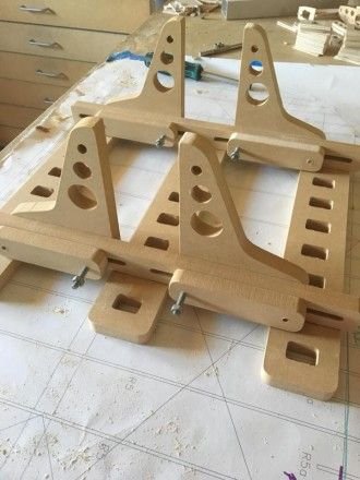
Found the plan on aerofred (search fuselage jig)
It seems to be nice since it looks to be able to be extended with a joiner.
Gotta get some material for it, cutting and gluing will probably take 2 or 3 days time.
08-30-2018, 08:00 AM
#6
Thread Starter
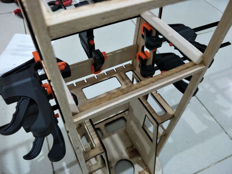
Phew... cutting the jig from 3mm (1/8 inch) ply and gluing them takes a total of 5 hours....
Thanks Barry for the plan https://aerofred.com/search.php?search_terms=all&search_keywords=fuselage+jig
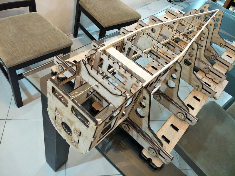
The fuse is "eye-balled-straight", well not really eye balled only, I pulled a string from the firewall and make sure everything is straight.
The rest was easy.
I reinforce the back part of the ply formers with some triangle stock, I should have removed the ply formers.
The fuse is now 400 gram. With turtledeck added, some servo mounting ply, and tail it could weight up to 700 grams at least, not counting landing gear.
The truss is a bit too much, I probably should have used 6x6mm balsa instead of 10x6mm. If I trim the truss, I might be able to save something like 50 grams or so.
The wing is now 800 grams.
Time for estimates.
700 fuse, 800 wings, 100gram spar and spar tube, 400gram servos, 300 grams rx and cdi battery, say 300 grams landing gear 200 grams covering, 50 gram tank, 150gram cowl and canopy. 1.25kg engine and cdi
that would be a total of 4.25kg.
I gotta be very careful with the tail.
after 3 hours of cutting
quite rigid, since my laser cutter only goes up to 50cm width, I had to modify the plan, and the result is only 200cm width of building space. I need to modify the vertical arm to allow wider build.
on the jig upside down
looks nice but 400 grams is a bit heavy
Thanks Barry for the plan https://aerofred.com/search.php?search_terms=all&search_keywords=fuselage+jig
The fuse is "eye-balled-straight", well not really eye balled only, I pulled a string from the firewall and make sure everything is straight.
The rest was easy.
I reinforce the back part of the ply formers with some triangle stock, I should have removed the ply formers.
The fuse is now 400 gram. With turtledeck added, some servo mounting ply, and tail it could weight up to 700 grams at least, not counting landing gear.
The truss is a bit too much, I probably should have used 6x6mm balsa instead of 10x6mm. If I trim the truss, I might be able to save something like 50 grams or so.
The wing is now 800 grams.
Time for estimates.
700 fuse, 800 wings, 100gram spar and spar tube, 400gram servos, 300 grams rx and cdi battery, say 300 grams landing gear 200 grams covering, 50 gram tank, 150gram cowl and canopy. 1.25kg engine and cdi
that would be a total of 4.25kg.
I gotta be very careful with the tail.
after 3 hours of cutting
quite rigid, since my laser cutter only goes up to 50cm width, I had to modify the plan, and the result is only 200cm width of building space. I need to modify the vertical arm to allow wider build.
on the jig upside down
looks nice but 400 grams is a bit heavy
Last edited by whiskey29; 08-30-2018 at 08:10 AM.
09-02-2018, 05:54 AM
#7
Thread Starter
16 days and I only got this far 
However, progress is progress.
I didn't like how thick the balsa I use for the truss.
The fuse weighted 393 grams, I thin out the truss and saved 16 grams.
Then I removed some more balsa and ply formers part where I don't think it adds structure strength.
At 369 grams, I saved 24 grams, not bad...
However, progress is progress.
I didn't like how thick the balsa I use for the truss.
The fuse weighted 393 grams, I thin out the truss and saved 16 grams.
Then I removed some more balsa and ply formers part where I don't think it adds structure strength.
At 369 grams, I saved 24 grams, not bad...
09-08-2018, 06:32 AM
#8

My Feedback: (4)
Hopefully this helps motivate you. I built this over 25 years ago and still fly it today. 105 inch wingspan powered by and OS 300 twin. It flies like a trainer. The in air pictures are from about 15 years ago from a friend that was flying his SuperCub while his photog wife took pictures. Get it done - you will enjoy it.
1/3 Scale Sig Spacewalker
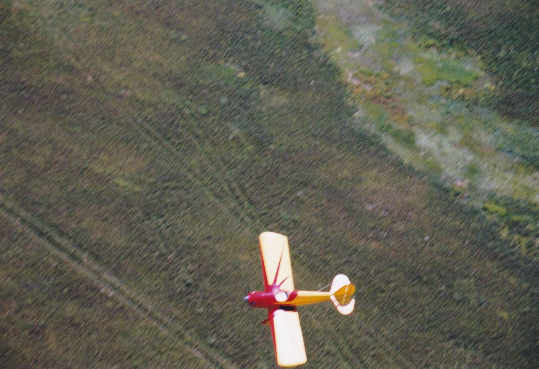
Photo taken from SuperCub
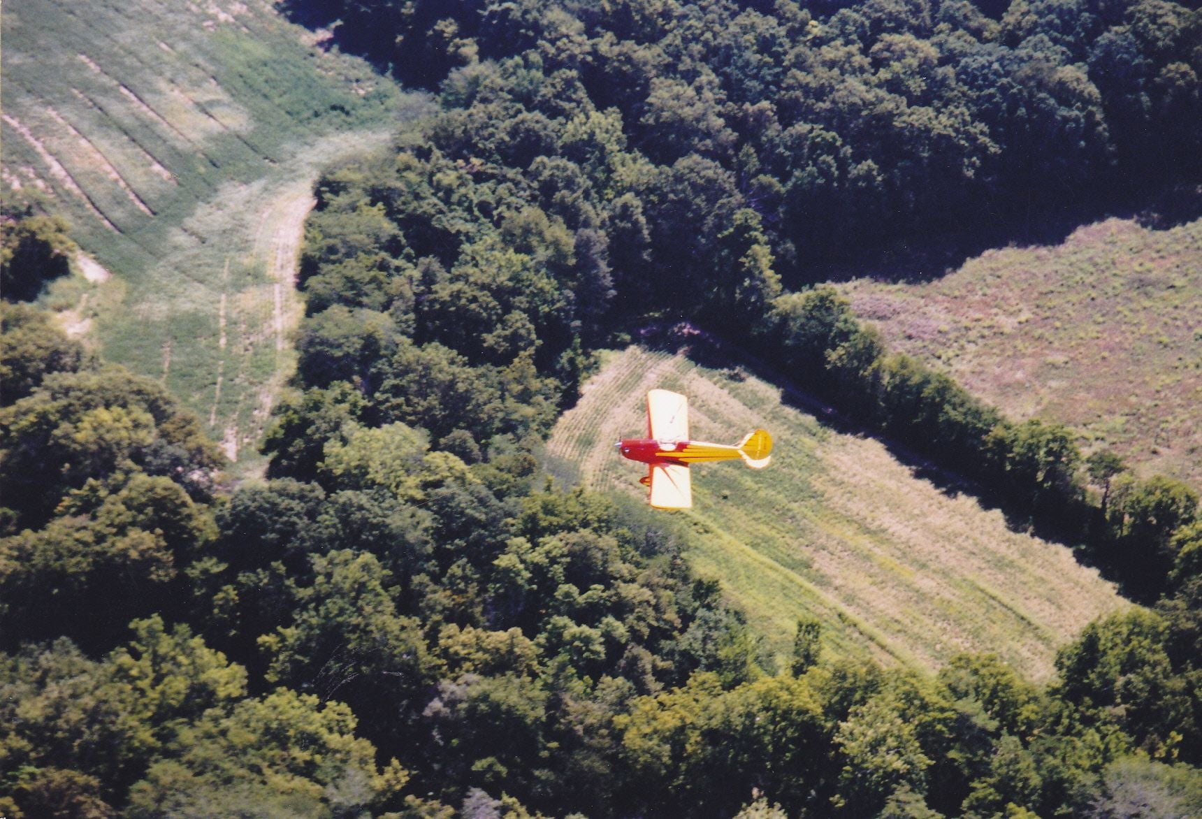
Photo taken from a SuperCub
1/3 Scale Sig Spacewalker
Photo taken from SuperCub
Photo taken from a SuperCub
 09-12-2018, 03:54 AM
#10
Thread Starter
@rcpilot100 Awesome picture, the aerial shot are awesome !!!! It looks great ! Thanks for the pictures.
At 105 w/s it makes the one I am making a lot smaller. How much fuel does that engine drink each 10 mins flight?
Time for an update for the build .
The past week was spent helping a friend putting together his Extra 300S ARF with 20cc DLE engine.
Not much progress with the spacewalker.
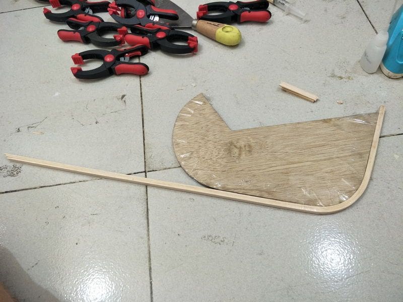
I have sanded the wing, and overshoot the trailing edge at the root Repair underway.
I did learned to tile print the plan on smaller paper with autocad,
created a jig for the rudder and elevator trailing edge,
and used 3 strips of 2mm balsa to create the trailing edge.
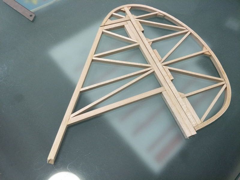
I managed to get the vertical tail and rudder done mostly, at 25 grams total I am very happy.
I cant decide on the horizontal tail yet, the plan call for stick construction, however I have created some holes for the spar and draw detachable stab with ribs.

At 105 w/s it makes the one I am making a lot smaller. How much fuel does that engine drink each 10 mins flight?
Time for an update for the build .
The past week was spent helping a friend putting together his Extra 300S ARF with 20cc DLE engine.
Not much progress with the spacewalker.
I have sanded the wing, and overshoot the trailing edge at the root
Repair underway.I did learned to tile print the plan on smaller paper with autocad,
created a jig for the rudder and elevator trailing edge,
and used 3 strips of 2mm balsa to create the trailing edge.
I managed to get the vertical tail and rudder done mostly, at 25 grams total I am very happy.
I cant decide on the horizontal tail yet, the plan call for stick construction, however I have created some holes for the spar and draw detachable stab with ribs.
09-14-2018, 09:06 AM
#11
Thread Starter
I have been learning Fusion 360 for the past 3 weeks.
I managed to draw the cowl in 3D and made a negative mold from it. I plan to 3D print negative mold.
I am sure its difficult to make smooth surface finish with the negative mold (putty, painting, polishing, etc).
Unsure how the epoxy will react to the plastic, I made two test pieces, one I will spray release agent directly, the other one I plan to cover it with some packing tape then lay the fiberglass.
If I can pull the cowl out, I can just do some finishing to make it looks good.
In the end if everything else failed, I can still print the positive mold, and have a friend to make the negative mold just like how it should be done.
I started to work on the stab, should be done tomorrow. Its 24 inches wide I decided to follow the plan, not removable.
It should be lighter, plus I don't have the need to carry the plane out of town.
I was going to have each elevator controlled separately, servos at front and use pull-pull.
But the extra servos and setup would not be worth it, its supposed to be relaxing to fly and does not need the extra hassle.
The plan call for 1/4 balsa as the leading edge for the elevator, I plan to use hardwood instead for the joiner.
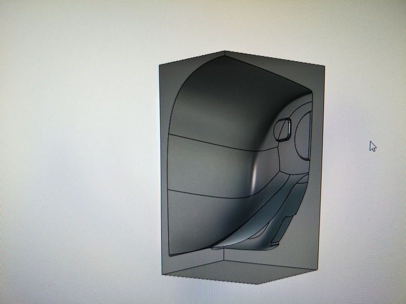
Negative mold of the cowl.

I follow the plan for the stab, unremovable
24 inches ! Small enough to fit my car.
I managed to draw the cowl in 3D and made a negative mold from it. I plan to 3D print negative mold.
I am sure its difficult to make smooth surface finish with the negative mold (putty, painting, polishing, etc).
Unsure how the epoxy will react to the plastic, I made two test pieces, one I will spray release agent directly, the other one I plan to cover it with some packing tape then lay the fiberglass.
If I can pull the cowl out, I can just do some finishing to make it looks good.
In the end if everything else failed, I can still print the positive mold, and have a friend to make the negative mold just like how it should be done.
I started to work on the stab, should be done tomorrow. Its 24 inches wide
I decided to follow the plan, not removable.It should be lighter, plus I don't have the need to carry the plane out of town.
I was going to have each elevator controlled separately, servos at front and use pull-pull.
But the extra servos and setup would not be worth it, its supposed to be relaxing to fly and does not need the extra hassle.
The plan call for 1/4 balsa as the leading edge for the elevator, I plan to use hardwood instead for the joiner.
Negative mold of the cowl.
I follow the plan for the stab, unremovable
24 inches ! Small enough to fit my car.
Last edited by whiskey29; 09-14-2018 at 09:14 AM.
09-15-2018, 06:57 AM
#12
Thread Starter
I finished the elevator this afternoon... It took me almost 2 hours.. too slow but I enjoyed it haha.
I love the sandwiching thinner balsa part to form the shape of the elevator, should have done that million years ago..
I made a mistake with the elevator.
I used "harder wood" for the elevator joiner at the splice I wrap PE fishing line and I just realized that I need to bevel that part .......insert dumb moment here...
The splice was glued using carpenters glue and now comes the dilemma. Should I just bevel the elevator part thus destroying the thread wrap, or bevel the stabilizer part ?
whats left to be done are :
- sanding the horizontal and vertical stab
- alter fuse at the tail section to accommodate the stab
- making removable top for the front fuse
- installing wing tube sleve and test fit
- do the landing gear
- gluing the stab to the fuse
- testing cowl building concept.
Phew... Looks like 2 or 3 more weeks....
09-18-2018, 11:27 AM
#13
My Feedback: (4)
Awesome build. There is a thread asking where all the builders are - I see there is a talented one here. My Spacewalker gets about 5-6 10 minute flights out of a gallon of glow fuel. If I built it today, it would have a gas engine in it. Something on the order of maybe 50cc - a 50cc twin would be outstanding. This photo is one of my friend Don Brann's Spacewalker. Don is on the left. On the right is Jess Anglin, the designer of the full scale Spacewalker. Somewhere I have a picture of 5 Spacewalkers that were at a meet I went to. The Spacewalker was built by many when it came out.

Last edited by RCPilot100; 09-18-2018 at 11:29 AM. Reason: Mispelling
09-19-2018, 05:05 PM
#14
Thread Starter
Awesome build. There is a thread asking where all the builders are - I see there is a talented one here. My Spacewalker gets about 5-6 10 minute flights out of a gallon of glow fuel. If I built it today, it would have a gas engine in it. Something on the order of maybe 50cc - a 50cc twin would be outstanding. This photo is one of my friend Don Brann's Spacewalker. Don is on the left. On the right is Jess Anglin, the designer of the full scale Spacewalker. Somewhere I have a picture of 5 Spacewalkers that were at a meet I went to. The Spacewalker was built by many when it came out.
I definitely going for gas now for bigger airplanes, glow fuels are expensive. I still miss the smell of the castor burning, and fly glow engines time to time.
As with the builder, I think with the availability of the ARFs there are more people that choose the easier path

I have been encouraging friends to build and so far only two taken that path..
09-29-2018, 11:59 PM
#15
Thread Starter
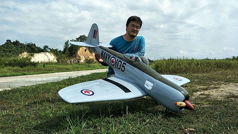
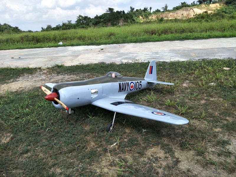
Spent 10 days last week building SeaFury that has been waiting in my garage for months 
Flew great with retracts, flaps and everything, it required 11 channel. I used taranis for that plane and put a receiver on the wing for 2 Ail, 2 Flaps and 2 Retract. Another receiver in in the body for the 2 elevator, rudder, throttle and kill switch.
I created the ducting for the engine with fusion 360 and printed with black PLA.
How do I know if the cylinder is overheating or not ?
In the middle of the flight, the top RPM sagged a little.
Back to the spacewalker.
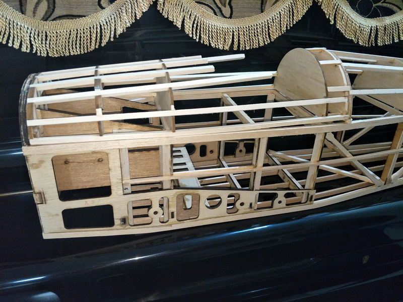
I have sanded the stabilizers, mod the fuse and install longerons for mounting the horizontal stabilizer, created the wingtips (havent glue them yet), fabricated the landing gear with some K&S steel. Soldering is not hard, the finish is acceptable for now and I hope it will survive many landings
Next I need to create the bottom hatch for landing gear access, top front hatch, install the wing tubes, preprare servo mounting for the wings, and it should be be ready for the cover.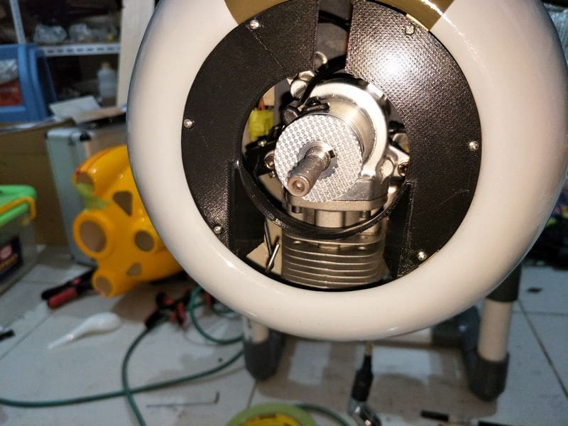
3d printed the duct.

tail section mod
wing tip cutting
looks good

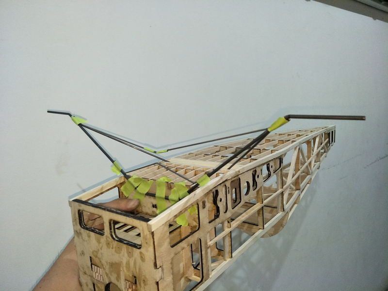
fabricating the landing gear
wheels seems a little to big
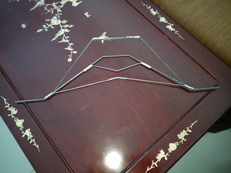
soldered
Flew great with retracts, flaps and everything, it required 11 channel
I created the ducting for the engine with fusion 360 and printed with black PLA.
How do I know if the cylinder is overheating or not ?
In the middle of the flight, the top RPM sagged a little.
Back to the spacewalker.
I have sanded the stabilizers, mod the fuse and install longerons for mounting the horizontal stabilizer, created the wingtips (havent glue them yet), fabricated the landing gear with some K&S steel. Soldering is not hard, the finish is acceptable for now and I hope it will survive many landings
Next I need to create the bottom hatch for landing gear access, top front hatch, install the wing tubes, preprare servo mounting for the wings, and it should be be ready for the cover.
3d printed the duct.
tail section mod
wing tip cutting
looks good
fabricating the landing gear
wheels seems a little to big
soldered
10-05-2018, 06:35 AM
#17
Thread Starter
I slowly will
Not much building time next week, I must travel for 3 days to visit a really close friend for her dad's funeral. Her dad and brother got hit by a cab in front of a hospital lobby in Singapore, her father didn't make it he was 72 the brother now is in intensive care unit. so much for a freak accident.
My new starter arrived designed and printed the battery tray. Old ones barely turn 30cc dle, new ones turns like its not there
Looks like its a small scooter starter, modified to be used with rc airplanes.
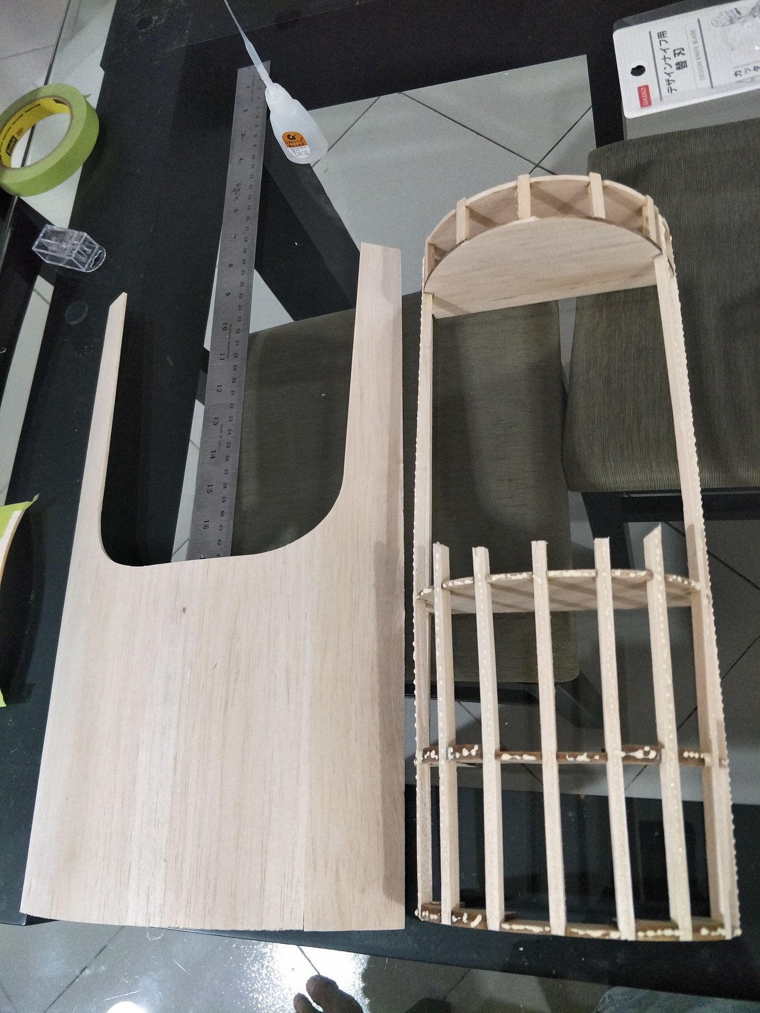
I got a bit of time to start working on the hatch, The slot for the longerons does not match, I had to re cut using exacto. I hope I got time to make and form the skin tomorrow.
The second longerons does not really match the slot at the back, i just notice it after they are all glued.
I wet the parts and mount the hatch on the plane while holding the hatch with some tape, hopefully when its dry it will conform more or less.
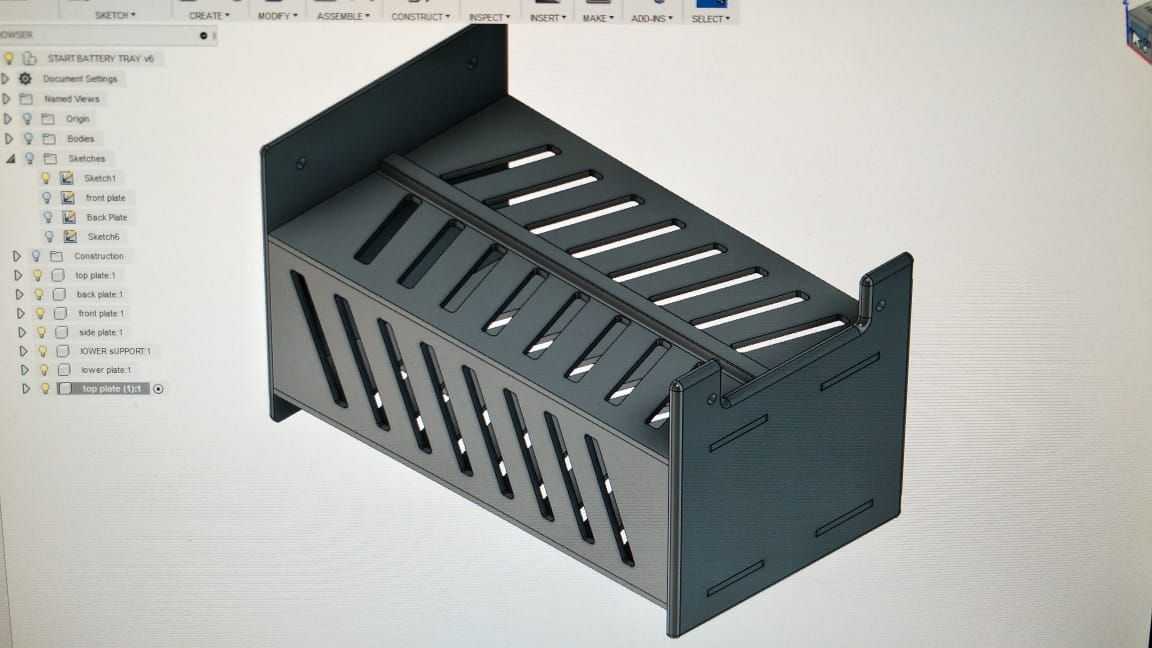
Designed the tray using Fusion 360, I think its the best thing I have learned doing the past 2 years.
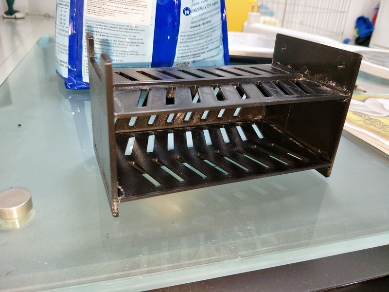
printed, glued.
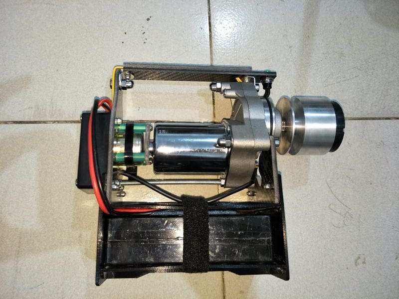
mounted, and portable.

some formers for the hatch all balsa.
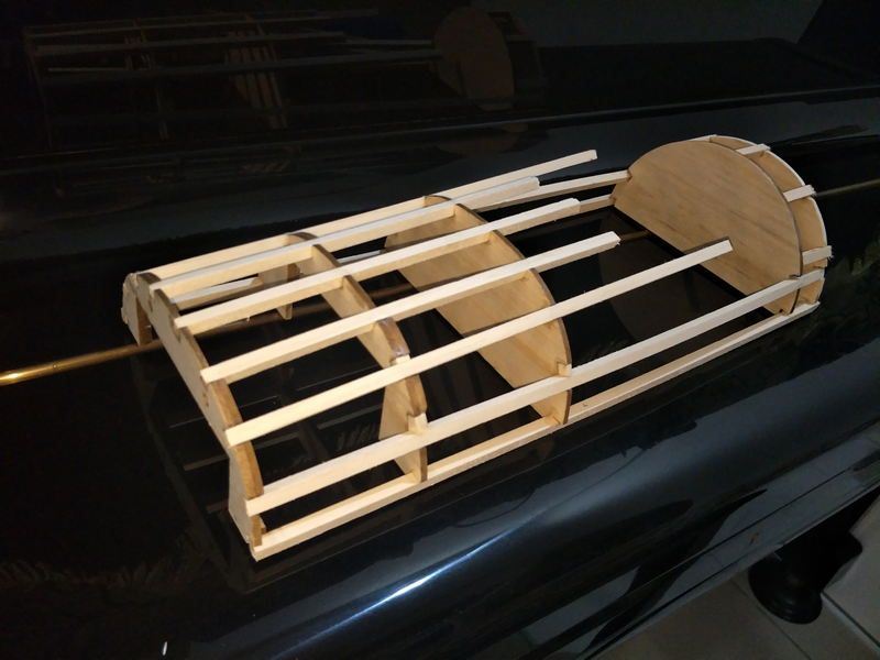
the second longerons pulling the whole hatch assembly upward at the back, I wet it, and secure the hatch on the fuse with some tape. fingers crossed.
Not much building time next week, I must travel for 3 days to visit a really close friend for her dad's funeral. Her dad and brother got hit by a cab in front of a hospital lobby in Singapore, her father didn't make it he was 72 the brother now is in intensive care unit.
so much for a freak accident.My new starter arrived designed and printed the battery tray. Old ones barely turn 30cc dle, new ones turns like its not there
Looks like its a small scooter starter, modified to be used with rc airplanes.
I got a bit of time to start working on the hatch, The slot for the longerons does not match, I had to re cut using exacto. I hope I got time to make and form the skin tomorrow.
The second longerons does not really match the slot at the back, i just notice it after they are all glued.
I wet the parts and mount the hatch on the plane while holding the hatch with some tape, hopefully when its dry it will conform more or less.
Designed the tray using Fusion 360, I think its the best thing I have learned doing the past 2 years.
printed, glued.
mounted, and portable.
some formers for the hatch all balsa.
the second longerons pulling the whole hatch assembly upward at the back, I wet it, and secure the hatch on the fuse with some tape. fingers crossed.
10-11-2018, 03:58 AM
#18
Thread Starter
Hatch is done. The weight is 61 grams all balsa, I am happy with it.
The skin is made of 3mm balsa, didnt wrap it long enough but the balsa is soft enough to bent.
I need to make some hatch latch and hide it inside at the base of the hatch.
I need to buy leather for the canopy trim, i will install it after covering.
I will weight the parts before covering.
A little more stuff to be done.
- installing plastic tubes for the pull pull both Rdder and Elevator.
- installing wing tubes and measure the wing incidence
- installing latch for the hatch
- making two undercarriage cover
- covering
- Installing electronics and engine
- making cowl.
A friend of mine will help me with the covering so I can focus on the cowl plug.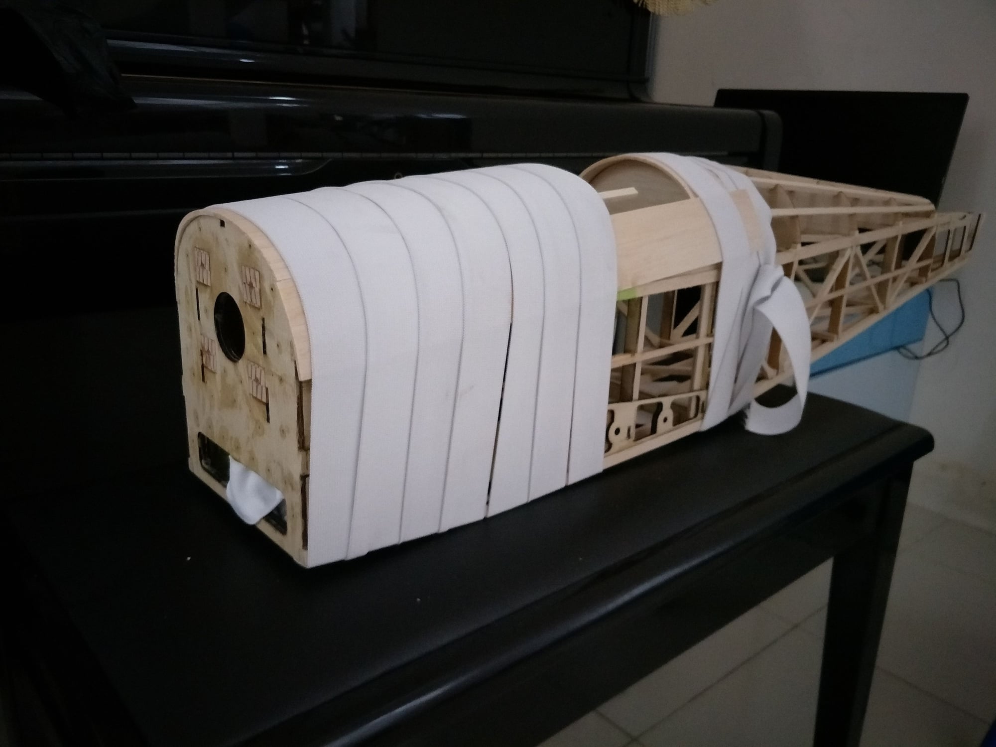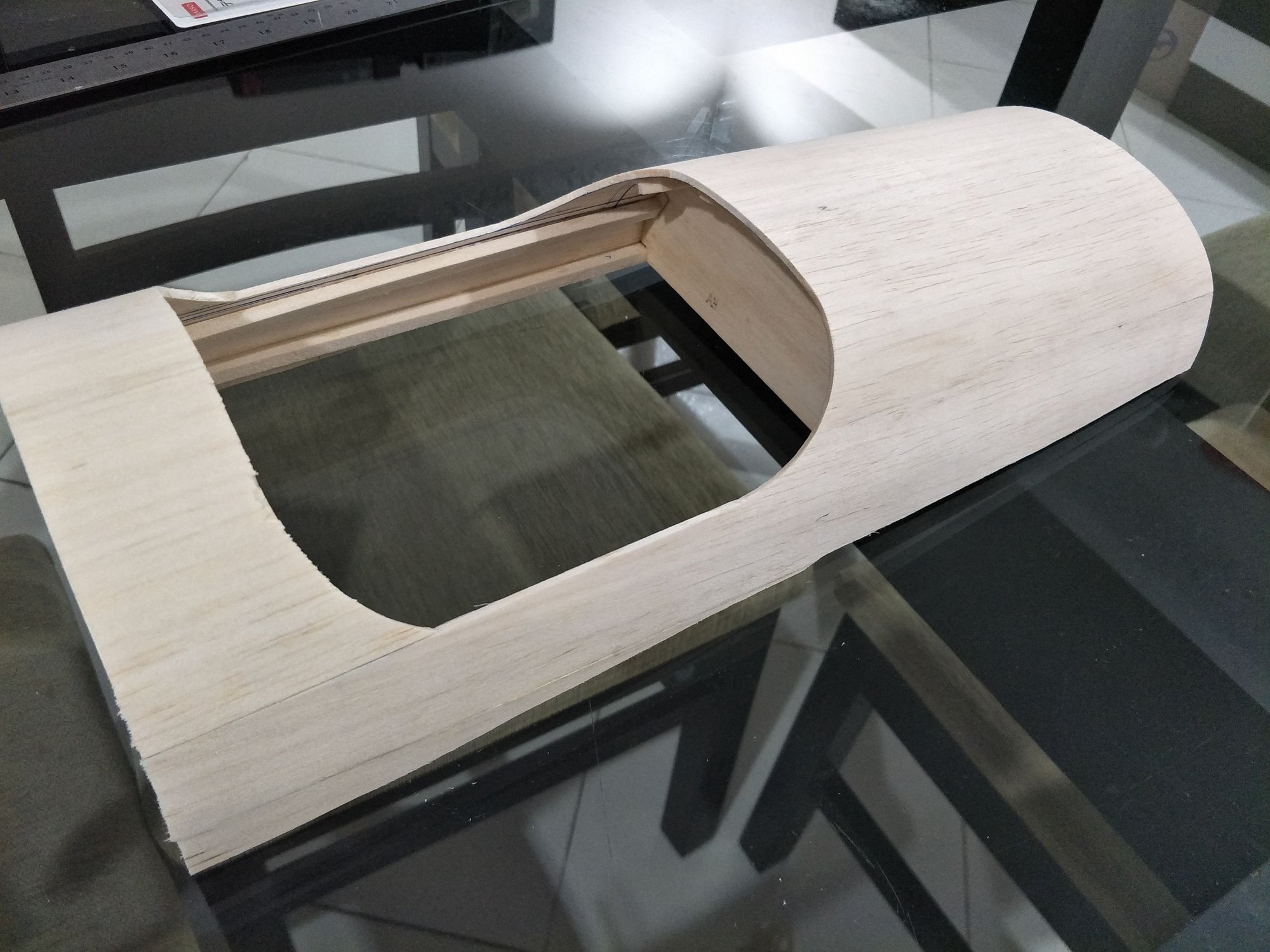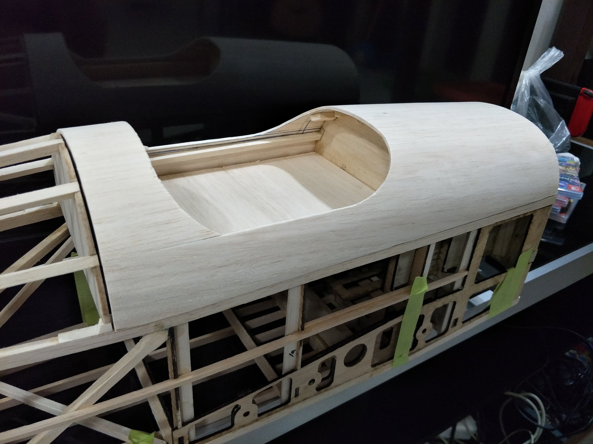
10-14-2018, 04:30 AM
#19
Thread Starter
Progress!!!
I needed latch for the hatch, however its no where to buy here, I downloaded from Thingiverse but its too big, I recreated it with my needed dimension, and had to use my daughters hair rubber band as I could not find any unused spring from pen.
The first version does not slide smoothly, as the rubber is pulling the pin towards the base and had the pin thread to scrub against the hole, I made second version, and installed short carbon tube accommodate a more horizontal rubber pull, now its acceptable.
I have installed the wing tubes and also the tubes at the body. The weight is light enough to make me happy
I just realized I need to extend the trailing edge to flush with the body, I will add 6mm balsa and sand.
The plane looks quite big now. If everything according to plan I should be able to maiden it in 2 or 3 weeks time.
I weighted most of the major parts now
1. Fuse with hatch is 510 grams
2. Vertical Stab and Rudder is 23 gram
3. Horizontal Stab and Elevator is 55 grams
4. Wing Joiner is 130 grams, I should have waited for lighter carbon joiner..... now they are different diameter.
5. Wing Tips 25 grams
6. Wing 789 grams
7. Landing gear 129 grams
8. Wheel 57 grams
9. Tail wheel 37 grams
10. Covering estimated 150 grams
11. Two battery 310 grams, 5 servo 300 grams
12. Cowl and wheel pants estimated at 250 grams.
13. Propeller 50 grams
13. Others like CDI cut off,receiver, horn, tank, canopy I estimate 150 grams.
14. Engine 1200 grams.
The total estimated take off weight is 4.165kg
estimated wing loading is 16oz/sq.ft
I am thinking to have the flap temporally fixed.
It may not worth it other than cool factor, to add 110 gram for 2 servo, while the wing loading is low enough for slow landing.
I will work on the wing tips tomorrow, it should be ready to cover in the next two days.


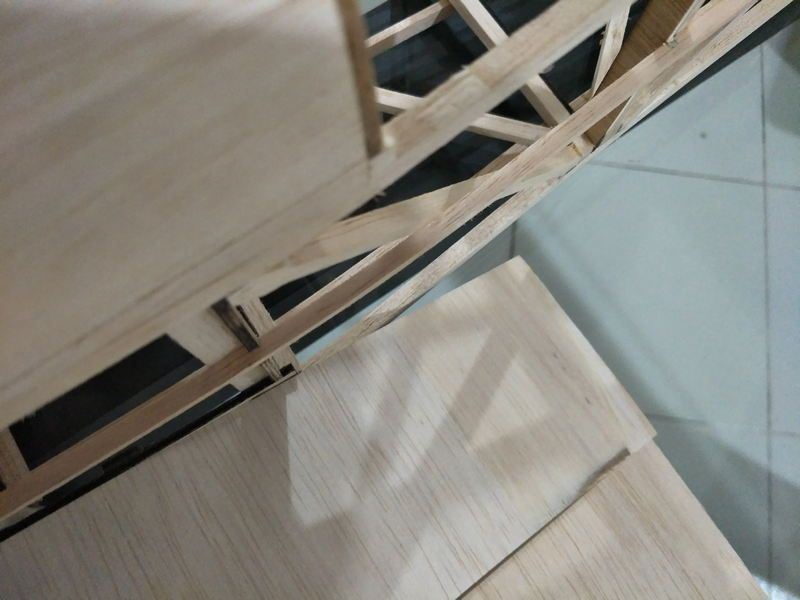
need to work on the gap from trailing edge to body
I needed latch for the hatch, however its no where to buy here, I downloaded from Thingiverse but its too big, I recreated it with my needed dimension, and had to use my daughters hair rubber band as I could not find any unused spring from pen.
The first version does not slide smoothly, as the rubber is pulling the pin towards the base and had the pin thread to scrub against the hole, I made second version, and installed short carbon tube accommodate a more horizontal rubber pull, now its acceptable.
I have installed the wing tubes and also the tubes at the body. The weight is light enough to make me happy
I just realized I need to extend the trailing edge to flush with the body, I will add 6mm balsa and sand.
The plane looks quite big now. If everything according to plan I should be able to maiden it in 2 or 3 weeks time.
I weighted most of the major parts now
1. Fuse with hatch is 510 grams
2. Vertical Stab and Rudder is 23 gram
3. Horizontal Stab and Elevator is 55 grams
4. Wing Joiner is 130 grams, I should have waited for lighter carbon joiner..... now they are different diameter.
5. Wing Tips 25 grams
6. Wing 789 grams
7. Landing gear 129 grams
8. Wheel 57 grams
9. Tail wheel 37 grams
10. Covering estimated 150 grams
11. Two battery 310 grams, 5 servo 300 grams
12. Cowl and wheel pants estimated at 250 grams.
13. Propeller 50 grams
13. Others like CDI cut off,receiver, horn, tank, canopy I estimate 150 grams.
14. Engine 1200 grams.
The total estimated take off weight is 4.165kg
estimated wing loading is 16oz/sq.ft
I am thinking to have the flap temporally fixed.
It may not worth it other than cool factor, to add 110 gram for 2 servo, while the wing loading is low enough for slow landing.
I will work on the wing tips tomorrow, it should be ready to cover in the next two days.
need to work on the gap from trailing edge to body
10-31-2018, 06:47 PM
#20
Thread Starter
Thanks, may be not too scale, I will work on getting it a bit more scale after test flight.
The fuse wing and stabs were sent to a friend, he will do the covering for me, The other spacewalker in kit form was sent to him as well, right now is being built by him.
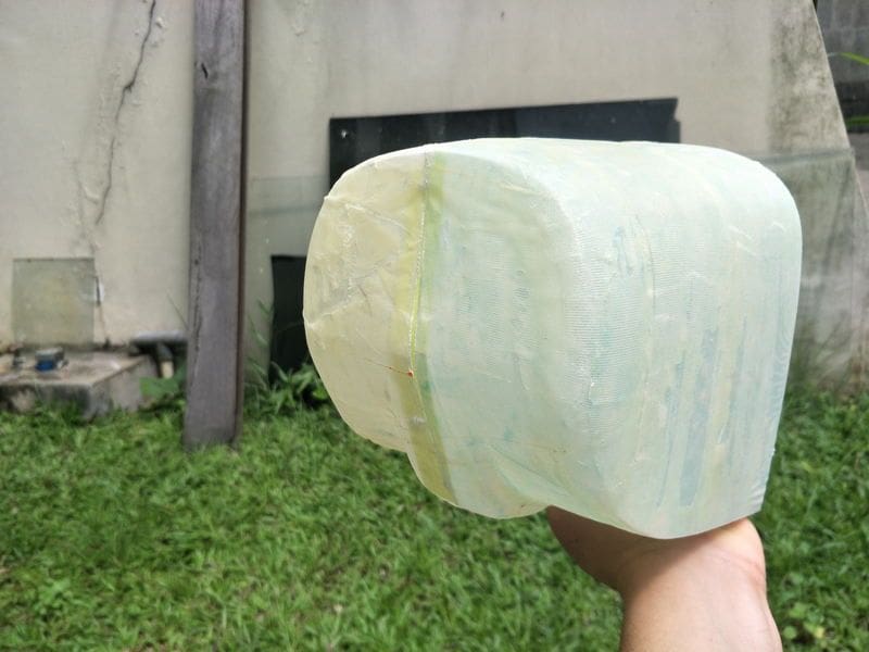
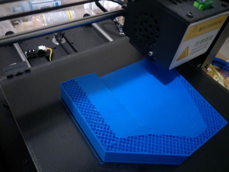
Mean while, I worked on the cowl it self, I printed the cowl as a two part positive mold, glued them together, fill them with car fillers, cover them with packing tape, laid fiberglass differently on each half and I found its easier to work with smaller piece of fiberglass
(For my future reference, I used 35 grams of epoxy on each half, I must apply the epoxy on the fiberglass before laying them on the mold and must absorb as much epoxy as possible with towel paper, also with packing tape, PVA is not needed)
The amount of resin is easier to control, as a result the second half has less resin and weigh a little less.
I could do better on the second cowl run, as I just found out the cloth that I used as wrap does not allow any resin to go thru..
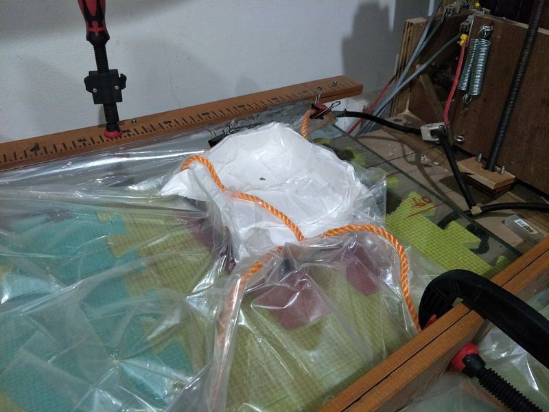
I wrap the mold with some stretch rubber fabric and opening them later feels like Xmas Whats better than unwrapping two presents from my self to my self
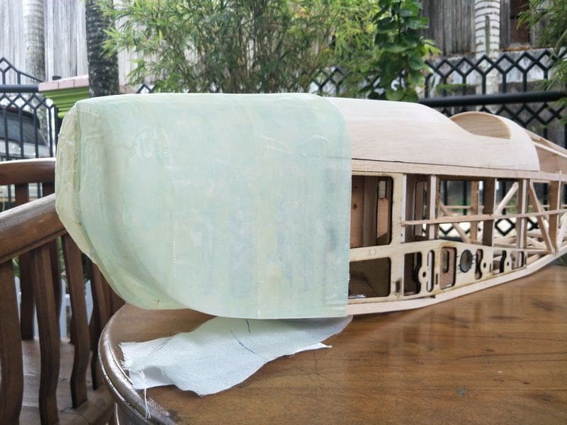
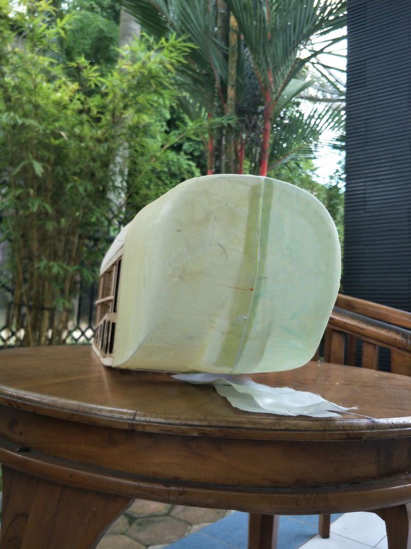
Pulled them out from the plug rather easily, next is to join them and paint them. I will bring the cowl to my friends house and see if it fits fine
After the second cowl is done, I will send the positive mold to a friend that work with fiberglass boat. I will ask him do the negative mold.
I am sure I can get better results that way, since I can control the thickness of the inside part of the cowl where the holes are, and keep the outer surface level.
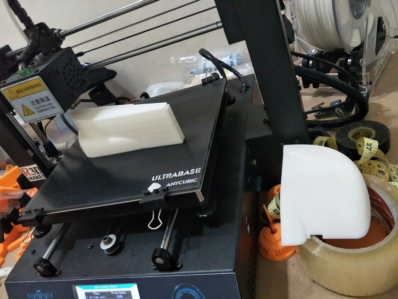
printing mold

CA glued

Filled with car filler
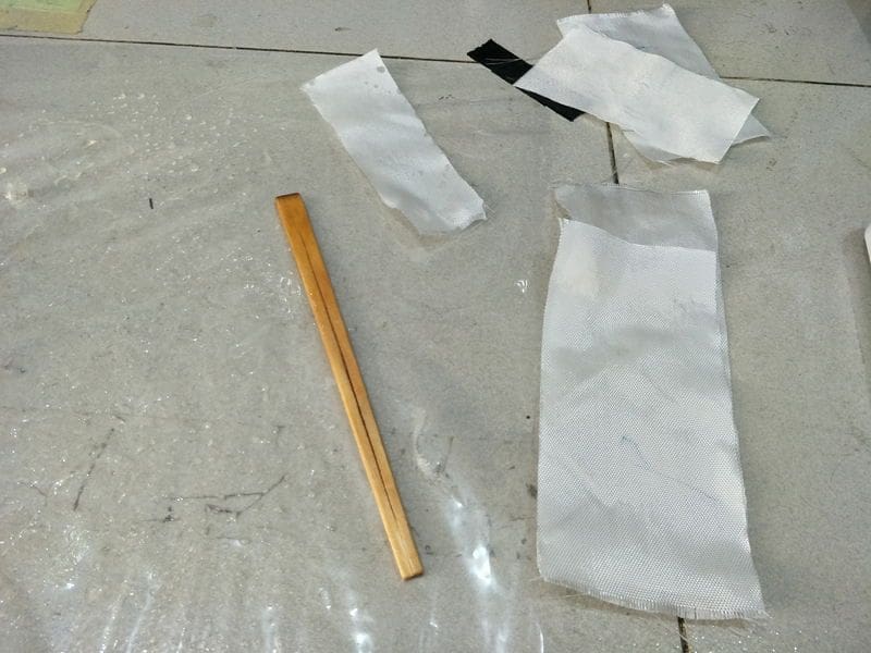
wetting cloth
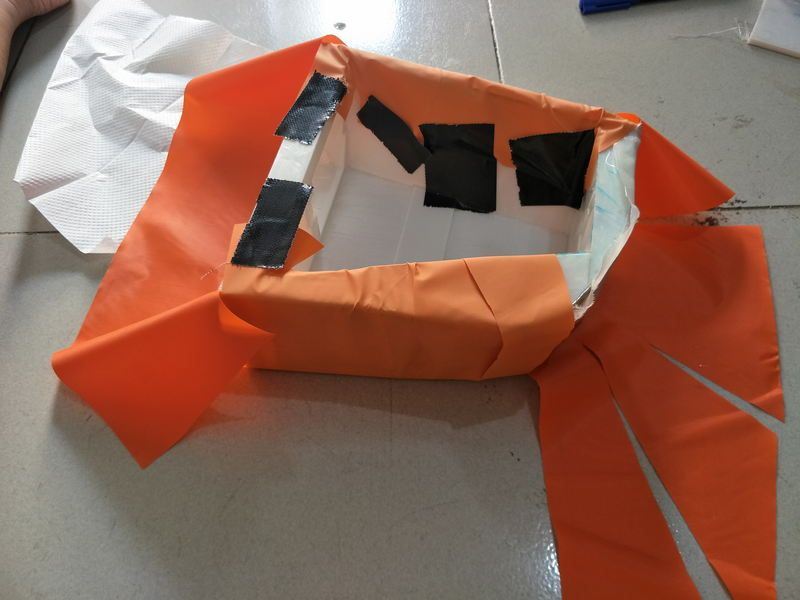
wrapping with nylon cloth
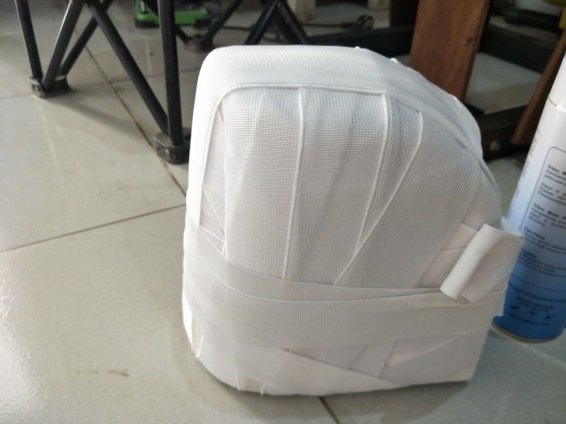
Mummyfied

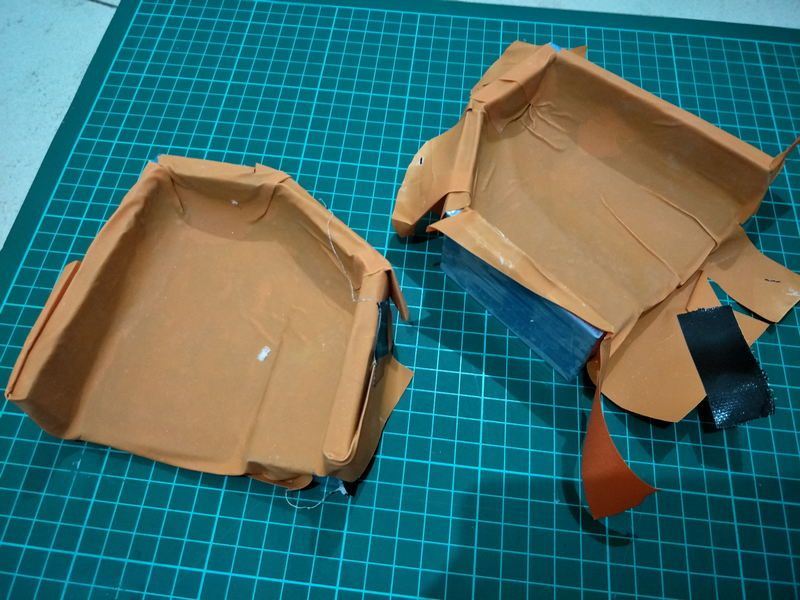
opening the present this morning.. can see the unevenness of the epoxy

opening second present
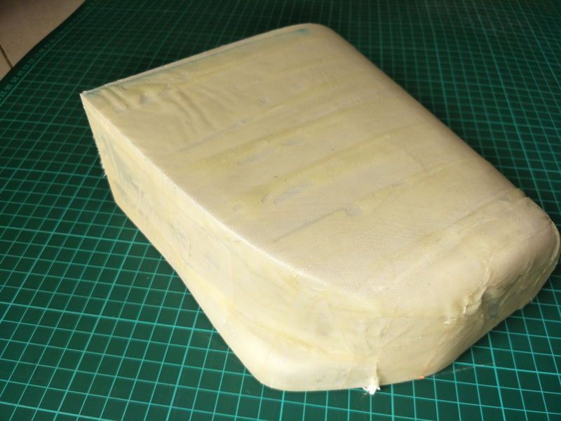
Too much epoxy

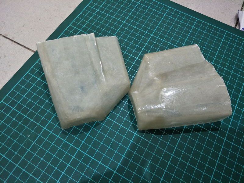
Much better

Looks like a cowl now
The fuse wing and stabs were sent to a friend, he will do the covering for me, The other spacewalker in kit form was sent to him as well, right now is being built by him.
Mean while, I worked on the cowl it self, I printed the cowl as a two part positive mold, glued them together, fill them with car fillers, cover them with packing tape, laid fiberglass differently on each half and I found its easier to work with smaller piece of fiberglass
(For my future reference, I used 35 grams of epoxy on each half, I must apply the epoxy on the fiberglass before laying them on the mold and must absorb as much epoxy as possible with towel paper, also with packing tape, PVA is not needed)
The amount of resin is easier to control, as a result the second half has less resin and weigh a little less.
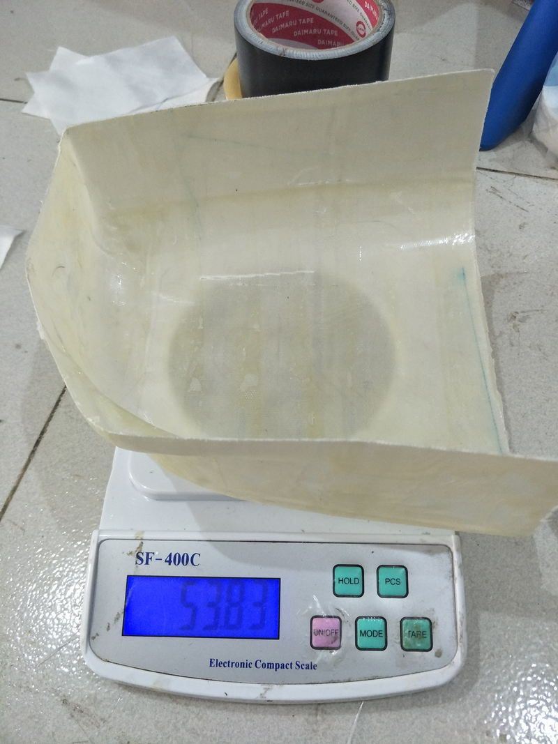
I could do better on the second cowl run, as I just found out the cloth that I used as wrap does not allow any resin to go thru..
I wrap the mold with some stretch rubber fabric and opening them later feels like Xmas
Whats better than unwrapping two presents from my self to my self Pulled them out from the plug rather easily, next is to join them and paint them. I will bring the cowl to my friends house and see if it fits fine
After the second cowl is done, I will send the positive mold to a friend that work with fiberglass boat. I will ask him do the negative mold.
I am sure I can get better results that way, since I can control the thickness of the inside part of the cowl where the holes are, and keep the outer surface level.
printing mold
CA glued
Filled with car filler
wetting cloth
wrapping with nylon cloth
Mummyfied
opening the present this morning.. can see the unevenness of the epoxy
opening second present
Too much epoxy
Much better
Looks like a cowl now
 11-05-2018, 07:49 PM
#22
Thread Starter
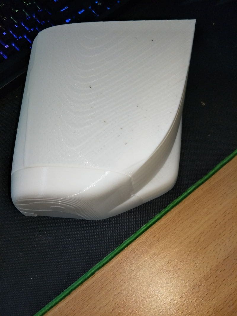
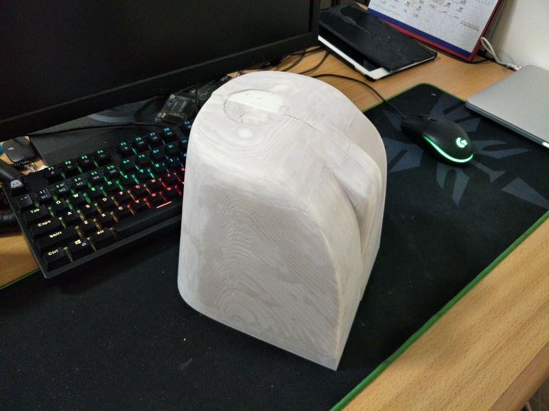
I printed negative mold for the spacewalker, the surface is not smooth and I know it will requires me do do some filling later with the final product.
So I printed another smaller cowl for experiment, its for a local rule pylon racer , I have been wanting to give it a cowl since two years ago Its a good opportunity to learn and see what I need to do differently, plus I must conserve the difficult to get thin epoxy.
Its not bad, just need some finishing, it came out pretty light as well 28 grams, total epoxy used was around 12 grams.
Currently I am joining both half in the mould.
Sharp corners are not a good friend My vacuum did a good job tho.


So I printed another smaller cowl for experiment, its for a local rule pylon racer , I have been wanting to give it a cowl since two years ago
Its not bad, just need some finishing, it came out pretty light as well 28 grams, total epoxy used was around 12 grams.
Currently I am joining both half in the mould.
Sharp corners are not a good friend
11-18-2018, 06:48 PM
#23

Join Date: Sep 2015
Location: Bellingen NSW Australia
Posts: 332
Likes: 0
Received 0 Likes
on
0 Posts
Nice work. I am watching closely and will get to read the thread all the way through soon.
I plan to build one too: 1/4 scale. I have a 30cc OPS Maxi engine converted to gas. Running on AvGas.Well, it will be when I receive the new carburettor for it.
Any updates since June?
Jim
Bellingen NSW Australia.
I plan to build one too: 1/4 scale. I have a 30cc OPS Maxi engine converted to gas. Running on AvGas.Well, it will be when I receive the new carburettor for it.
Any updates since June?
Jim
Bellingen NSW Australia.
11-25-2018, 08:45 AM
#24
Thread Starter
Hi Jim,
Currently we are preparing for a regional competition in early December, so all efforts and focus are used for preparing for the competition.
We will resume working on the plane, mid December.
The plane is at covering state now, and a friend will help me with that, I left the plane at his house, so he can have ideas on building the second one that I cut for him.
I will work on the cowl, the negative print is done, i just need to put them together.
I am sure your engine will have better power than mine flying the 1/4 scale spacewalker.
Irwan
06-16-2019, 05:40 AM
#25
Thread Starter
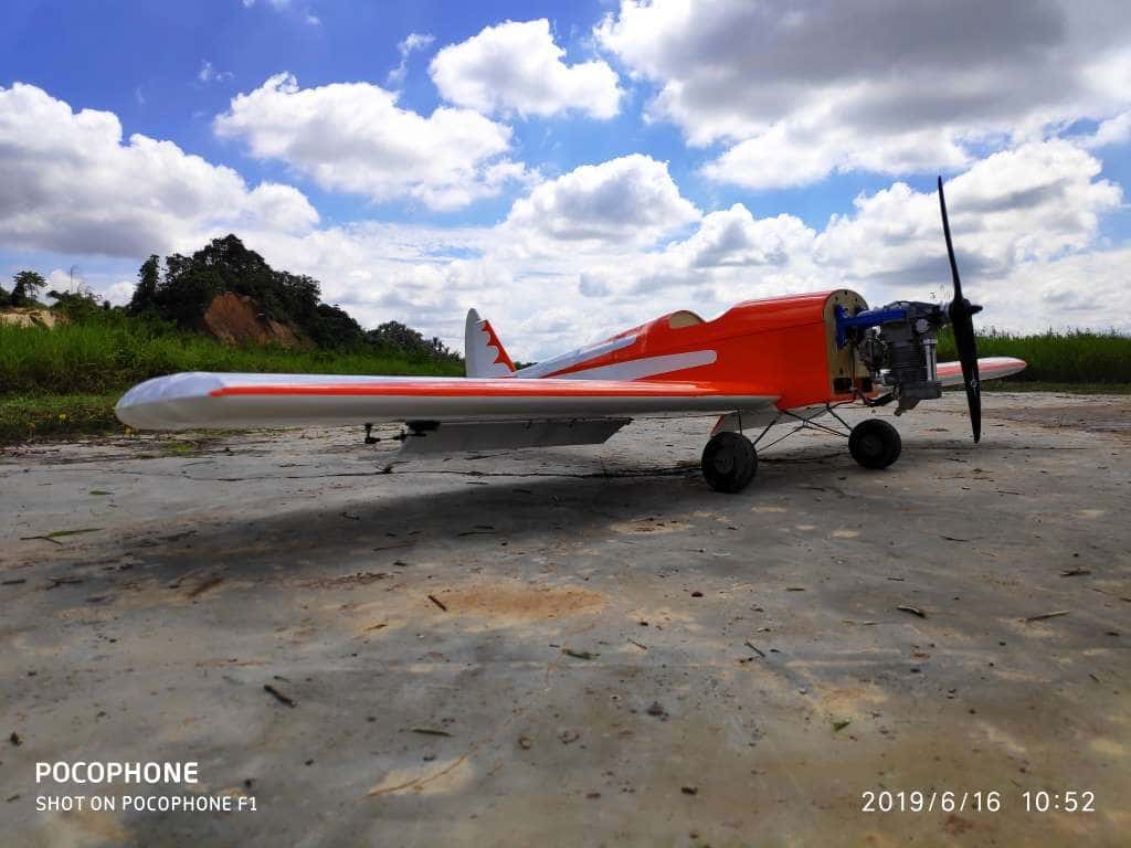
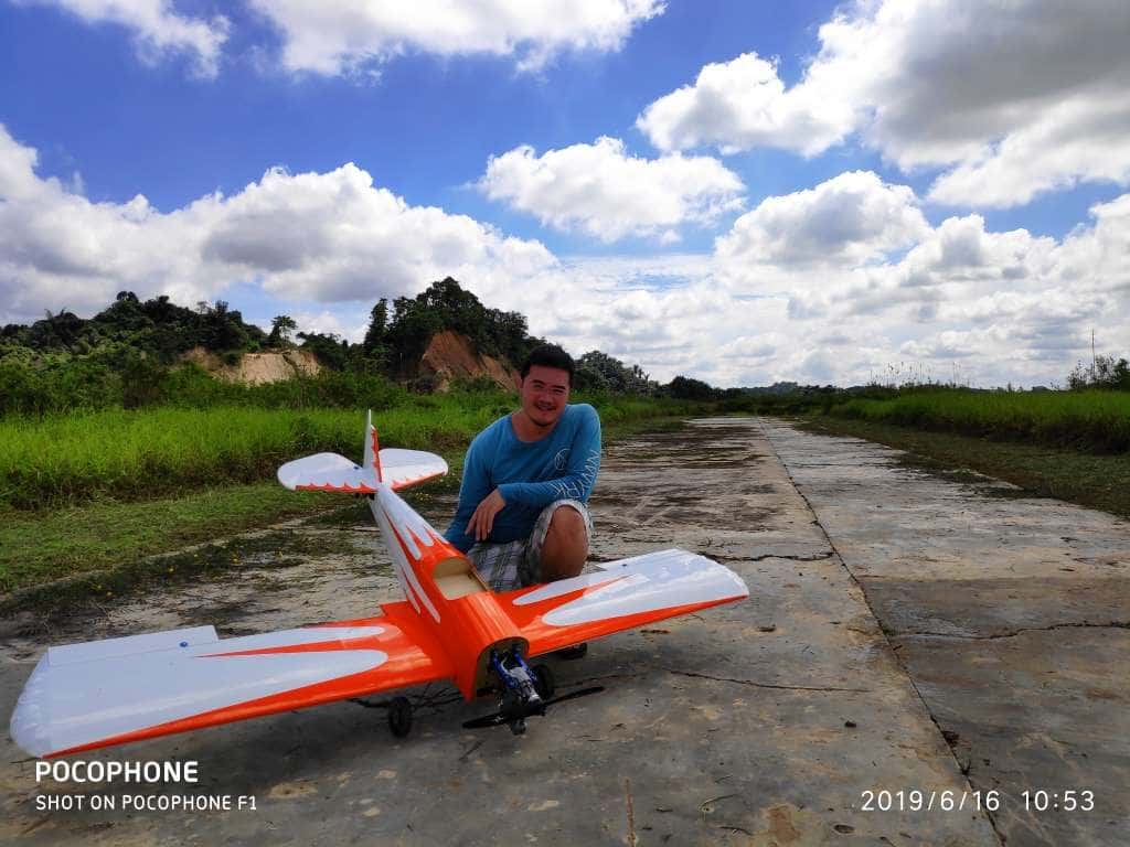
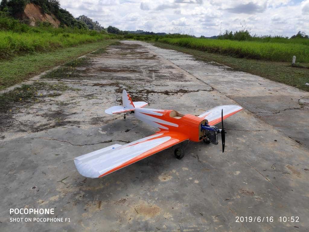
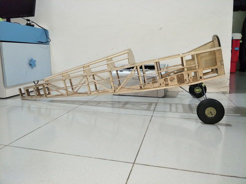
It flew !I managed to finish it enough for maiden flight, cowl is in progress, the mould has been glued and sanded I will try to paint it then prep it for mould.
The landing gear center brace needs to be stiffer, I plan to replace it with 3mm wire.Flying weight isunder 5kg, but I will weigh again when I have the cowl done.
The flight it self was great. Very gentle, no tip stall and does slow down. Its a joy to fly and one of my favorite now
I am eyeing on pitts s1-s now wing drawing is done, and I have traced the formers as well,
The landing gear center brace needs to be stiffer, I plan to replace it with 3mm wire.Flying weight isunder 5kg, but I will weigh again when I have the cowl done.
The flight it self was great. Very gentle, no tip stall and does slow down. Its a joy to fly and one of my favorite now
I am eyeing on pitts s1-s now
wing drawing is done, and I have traced the formers as well,