


C-141 design
 09-24-2018, 11:30 AM
#1


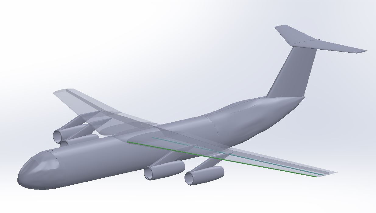
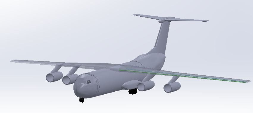
Started a project to create a RC model
3D model started, but am still looking for better information
Model is based on the Roden plastic model, and various technical manuals and three views
Current size is 120" wingspan with an estimated weight of 22 Lb
Nacelle's internal diameter is approx 100mm
Feedback on a suitable power system would be appreciated
Bob
Last edited by limeybob; 09-24-2018 at 11:32 AM.
 09-25-2018, 04:09 PM
#2

Join Date: Aug 2016
Posts: 104
Likes: 0
Received 0 Likes
on
0 Posts
Man, that takes me back. I grew up in the 82nd ABN, 1/325 AIR. I remember jumping out of those things....lol.
Have you watched the youtube channel "DAGS" aircraft design? He has some great insights into cargo planes and building in general.
Are you going to make a plug, or do a built up fuse?
Cool project!
Have you watched the youtube channel "DAGS" aircraft design? He has some great insights into cargo planes and building in general.
Are you going to make a plug, or do a built up fuse?
Cool project!

 10-01-2018, 07:35 AM
#7
My Feedback: (22)
Join Date: Jan 2002
Location: East Brunswick, NJ
Posts: 182
Likes: 0
Received 0 Likes
on
0 Posts
I hope Bob can develop some usable plans. Cheers
Stan
10-01-2018, 03:59 PM
#9
My Feedback: (22)
Join Date: Jan 2002
Location: East Brunswick, NJ
Posts: 182
Likes: 0
Received 0 Likes
on
0 Posts
Thanks Bob, Have you checked out C141heaven? Lots of info there.
https://c141heaven.info/dotcom/index.php
https://c141heaven.info/dotcom/index.php
10-09-2018, 10:43 AM
#11


Join Date: Oct 2002
Location: Chilliwack, BC, CANADA
Posts: 12,425
Likes: 0
Received 22 Likes
on
19 Posts
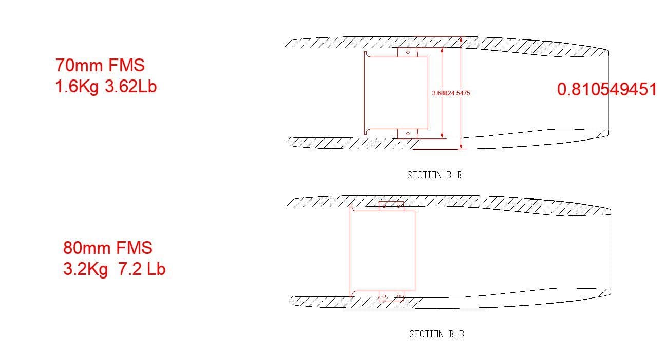
Bob, are you keen on keeping the model as clean and scale like as possible? I ask because at first glance it would be nice to use ducted fans.... .assuming that the budget for actual turbines is not in the picture? Because two small turbines in the inner nacceles would be amazing.
If not turbines the thing with EDF's or glow power DF's is that there's a lot of noise for not much push. Great for flying fast but not so great for getting a big model moving along from a standstill and climbing away. Especially out of a small'ish ID like just 100mm. So my idea is engines or motors that stick out the front of the nacceles just a little and props on the front that can do a better job of accelerating and climbing at a more scale like speed. After all these things look like they float up off the runway due to their size in real life. In flight the props would be all but invisible.
I know it's a slap at the idea that these are "jets". But it would likely make for a better flying model that uses less power to fly due to the props being more efficient than fans for the sort of flight performance that I'm thinking you'll want.
 10-10-2018, 12:08 PM
#15
Join Date: Oct 2002
Location: Chilliwack, BC, CANADA
Posts: 12,425
Likes: 0
Received 22 Likes
on
19 Posts
Bob, are those ratings the thrust per unit? That's pretty darn impressive if they are! But what sort of watts does the 80mm unit pull to produce that thrust?
Not that it really matters. You're going to have lots of wing area to lift the batteries either way.
I wonder if the sound of the 80mm fans running at a little down from full throttle might also have a nicer sound than the smaller 70's running at full throttle?
Not that it really matters. You're going to have lots of wing area to lift the batteries either way.
I wonder if the sound of the 80mm fans running at a little down from full throttle might also have a nicer sound than the smaller 70's running at full throttle?
10-10-2018, 12:26 PM
#16
FYI, This is the response we got when we requested a propulsion solution
Quote
"
Quote
"
The main problem that some scale RC jets don't perform well, is due to the aircraft ending up being grossly overweight, from the original AUW estimate. You should aspire to the aircraft having at least 0.8:1 power to weight ratio (for an airliner model) at takeoff, and cruising at 50% throttle.Considering the size of your nacelles, I feel that the Jetfan 80mm https://www.effluxrc.com/Jetfan-80mm...t-JF-80EDF.htmwould be a good fit. The Fan O.D. is 82 mm and the mounting tabs are .47" wide each. You might need to narrow up the tabs a bit.Considering that with all the scale details, The AUW might be 25 lbs, my suggestion would be to use 4 HET 700-60-2085 motorshttps://www.effluxrc.com/HET-700-60-...70-60-2085.htm (using 6s, 4000-5000 mA lipos and castle Edge 100 ESCs. for 2.85kg thrust @ 94A. This would be 25.12 lbs thrust total for 4 engines. This would give you 1:1 and certainly plenty of authority. You could cruise throttled way back. If you think less power would suffice. You could run the lighter, lower kv HET 650-58-1970 motor, although this motor is not on the chart.https://www.effluxrc.com/HET-650-58-...50-58-1970.htm
10-11-2018, 09:56 AM
#17
Join Date: Oct 2002
Location: Chilliwack, BC, CANADA
Posts: 12,425
Likes: 0
Received 22 Likes
on
19 Posts
I'm used to power to props so those numbers pretty much floor me. At full throttle that works out to 360 watts per lb and a total of 9000 watts at full throttle from all four motors.
I believe that it's a case of the thrust to power goes up a little as the diameter of the EDF fan increases, right? I'm wondering if you give any consideration to fudging the nacelle size or construction a little to allow fitting a larger diameter fan unit?
Off the top of my head I'm thinking a thin walled molded fiberglass center ring with a much modified method for holding the fan unit in place that does not take up the room which the tabs seem to require. That would allow you to fit at least the 90mm fan into the scale size nacelle. Added on each end would be the removable inlet and efflux nacelle rings. Or perhaps the inlet ring would be done as an integral part of the center and only the rear efflux ring would be removable so the EDF units can be installed from the rear. The inlet ring would take the place of the inlet lip of the fan unit with an ID that precisely matches and fits the fan. So no discontinuity there and maximum use of the nacelle diameter. And a similar treatment for the outlet ring to ensure the velocity of the air is maintained by not causing any turbulence as it leaves the end of the fan unit.
And with just a slight non scale fudging to enlarge the diameter of the nacelles a similar setup would hold the 100mm unit quite compactly.
Leaping ahead further with this I'm thinking thin turned rings with gear like teeth on the edges to lock the fan unit to the outer nacelle center ring. The teeth being on the edges of the rings with one secured to the outer nacelle ring and the other to the fan unit. This toothed ring pair would be at the front of the EDF. And there would be another ring at the rear of the EDF that simply centers the EDF unit. The gap between the outer nacelle and motor that the rings require would also be where the motor wires run. The thickness of these rings being just thick enough to allow the wires to be run without sticking. The rear efflux ring would them mount into position and that would lock the EDF unit in place firmly.
Mind you all this blue skying I'm doing falls flat on its face if the larger EDF units with suitable lower power motors won't give you more push per watt and enough to get off the ground. The goal being if the larger fan units will operate more efficiently and thus allow you to run smaller and lighter motors, ESC's and battery packs. My thinking on this stuff might well be all wrong since I'm not really a "fan guy".
It's a helluva project that has clearly seen a lot of thought already. I'm sure I'm not the only one that is curious about the choices that go into such a thing.
More goofing around with random thoughts and going back to a prop solution just for giggles.....
It's pretty well a given that for a 1:1 thrust to weight ratio with sport model style props that it requires roughly 100 watts per pound. So if there were props sticking out the front of the nacelles you could reach that same 1:1 thrust to weight with four motors that are handling around 600 watts each. And likely would not even need to run them up to more than around 400 to 450 watts each even for takeoffs. Looking at Eflite motors their 25 size motor is good for 850 watts, only needs a 4S pack and is 6.5 oz instead of 10 oz. So it would be loafing along when proped for 600 watts output. The Eflite 15 is good for 575 watts. And even at 500 watts would still be up at the 0.8:1 thrust to weight range. and well up there with 2000W / 25lbs= 80 watts/lb All good numbers. And the motor weight drops down to 5.5 oz. So I wonder if the reduction in needed structure and power components might well add up to a total weight reduction down to maybe the 18 lb range?
The big downside of course though is the odd look of props on a jet. Fine for sport flying perhaps. But this is a far more grand design and I can see why you're committed to doing it proper with the fan units.
 10-12-2018, 03:45 PM
#20
Join Date: Oct 2002
Location: Chilliwack, BC, CANADA
Posts: 12,425
Likes: 0
Received 22 Likes
on
19 Posts
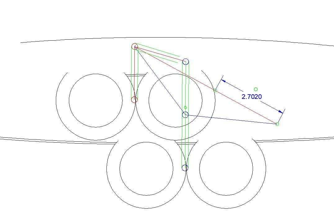
How much do you think the total gear assembly for each side will weigh?
If you used a linear actuator that when collapsed lays on that lower blue below the 2.7020 number than extends out and up to the line with the travel measurement take note that due to pushing off the upper portion that hinges up and forward that the force needed will also multiply. So it'll require a fair bit more for the last portion of the lift than what the leg and wheels actually weigh. If you remember your vector diagrams and forces you can plot out the push needed at the angle shown to lift the lower leg and wheels. The horizontal portion of the force will be reflected in the upper leg that pivots up and forward. Due to the angle more than half the push from the actuator would be lost in the upper leg.
Now that's if you want to use a linear servo. If you use a 160 to 180� retract servo in place of the linear servo there would still be a big increase in force right at the end but due to the arc of travel of the output arm the pushing force of the servo would be increased. So it may not be that bad. The rotary servo in this case would have the output arm centered on the middle of your 2.7" extension and to gain some help would arc downwards and forward from the rear lowered position and up to the retracted position. Due to the arc moving low and then up the last portion of the retract cycle would gain from the way the arc levers the gear arm into place. And of course you'd need a 1.3" long arm and a full meal deal 180� servo. The 160� would work but with a slightly longer arm. And I'd align the arm so the force increasing portion of the arc of travel puts the arm and servo center in line with the final retracted position of the link.
 10-12-2018, 04:20 PM
#22
Join Date: Oct 2002
Location: Chilliwack, BC, CANADA
Posts: 12,425
Likes: 0
Received 22 Likes
on
19 Posts
Do they have a longer stroke version? Your other sketch calls for 2.7". But yeah, that looks nice if it's got the required moxy.
The LG sketch shows the retracted gear/ extended actuator line as being roughly 30� from horizontal. That's a handy number since the sin of 30 happens to be 0.5 And that means that if the wheels bogie and lower leg is 16oz, for sake of discussion, that the actuator needs to push with twice that much at the angle it would be at. I'll leave it to you to fill in the actual numbers. But the multiplication factor is weight of that lower assembly over the sin of the angle of the actuator and any extension rod.
Actually you'll need a touch more than that. The upper leg being past horizontal means it will be pushing down a little. But it's fairly minor. Go with a healthy amount more power from the servo or linear than twice the weight of the lower section and you'll be good.... unless the rising gear will also pull up the cover doors? Might need a bit more in that case.
10-12-2018, 09:05 PM
#24
Join Date: Oct 2002
Location: Chilliwack, BC, CANADA
Posts: 12,425
Likes: 0
Received 22 Likes
on
19 Posts
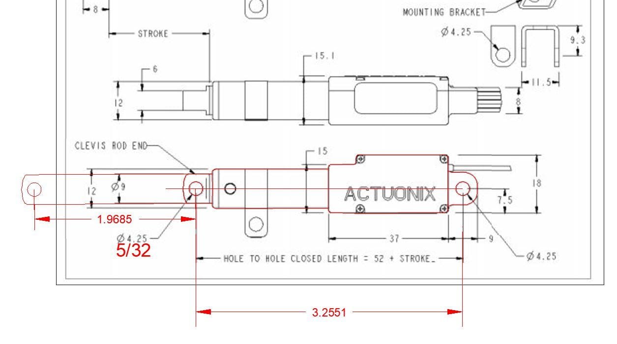
Those are not a bad price for that sort of product at all. And I like that they are directly compatible with the output from "our" receivers. But it's too bad that they don't have a 75mm stroke model between the 50 and 100. So you're going to have to go for the 100mm stroke model. Will that cause a problem with the room in the LG fairing? I'm not seeing any specs on the size for the 100mm stroke option.
10-13-2018, 01:00 PM
#25

Why reinvent the wheel with a "linear actuator " when you can just get a big (giant scale) servo and run a linkage to it.?
Last edited by allanflowers; 10-13-2018 at 01:01 PM. Reason: spelling