


A question about washout - Defiant project
 04-27-2023, 01:49 AM
#1
Hi All,
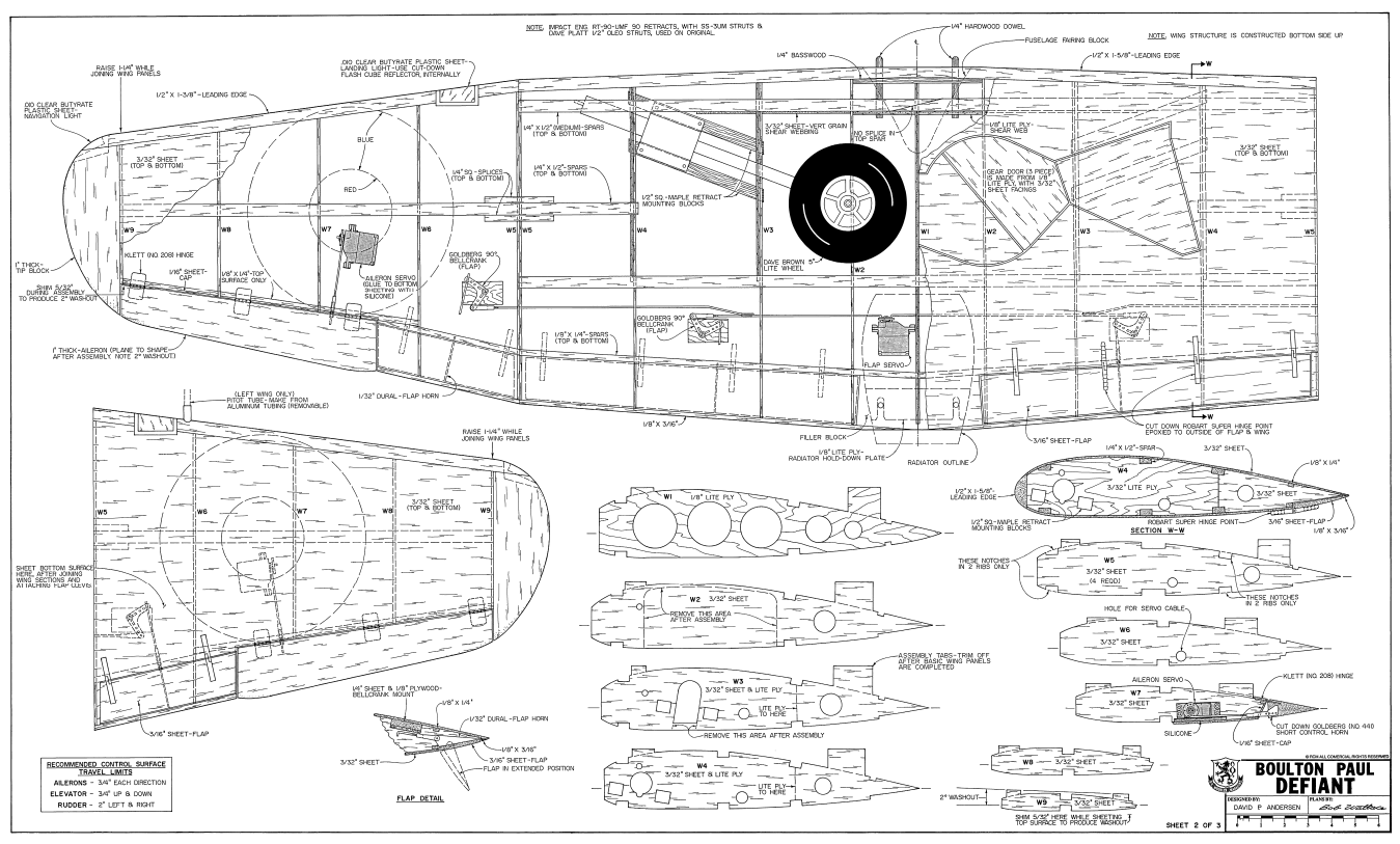
I started a while back building a Bolton Poul Defiant from plans downloaded from https://outerzone.co.uk/plan_details.asp?ID=6347 . Things are moving slowly, but I have had a steady progress the last months. Fuselage frame build and started sheeting and wing center section built and sheeted. I am now moving over to start building the tip sections for the wing. Studying the plan and rib patterns, I can see that the washout (2deg) is only built in at the last 4-5" of the wingtips. All ribs expect for the outermost are set with with 0deg incidence. Why?? There will be a noticeable twist built in at the outer tips which may be hard to make look nice. Would it be better to just build in 2deg washout which goes over the whole length of the tip sections? I am very tempted to do it this way as this is what I see as common.
What are your opinions regarding this?
 04-29-2023, 10:53 PM
#2

My Feedback: (60)
Join Date: Dec 2001
Location: Litchfield Park,
AZ
Posts: 7,677
Likes: 0
Received 25 Likes
on
23 Posts
Yes, the wash-out needs to be distributed through the entire wing panel. Having said that, David P. Andersen is a very well respected designer and many aircraft have been built from his plans.
04-30-2023, 08:23 AM
#3

I looked at the plan and the designer wants the outer wing tip panel from the die hederal break out to have the washout. you can only create washout at the far end of the wing
04-30-2023, 08:41 AM
#4

I had a look at the plans and re-read the article. At one point I had, and may still have that issue of RCM. As I read the construction article it looks like the intention was to prop up the outer most rib to induce a twist in the entire wing panel. It only gets a couple of lines on the actual procedure followed by a line about how important it is. I've thought this was an under appreciated airplane. Hope to see a photo of your model.
05-01-2023, 01:07 AM
#5
Hi All,
If you study the drawing a bit closer, you will see that the building tabs on all ribs except for the W9 builds in no incidence. The washout is only built in between rib W8 and W9, which will cause a very noticeable twist. This is why I do raise questions about this design. I have checked the CAD models of the ribs also, and all of them except W9 has its centerline parallel to the building tabs and flat section on the bottom.
I do plan to built the wing with a 2deg washout distributed from the tip dihedral brace / W5 instead. This will look better and better match common practice. Any reason for not doing it like this?
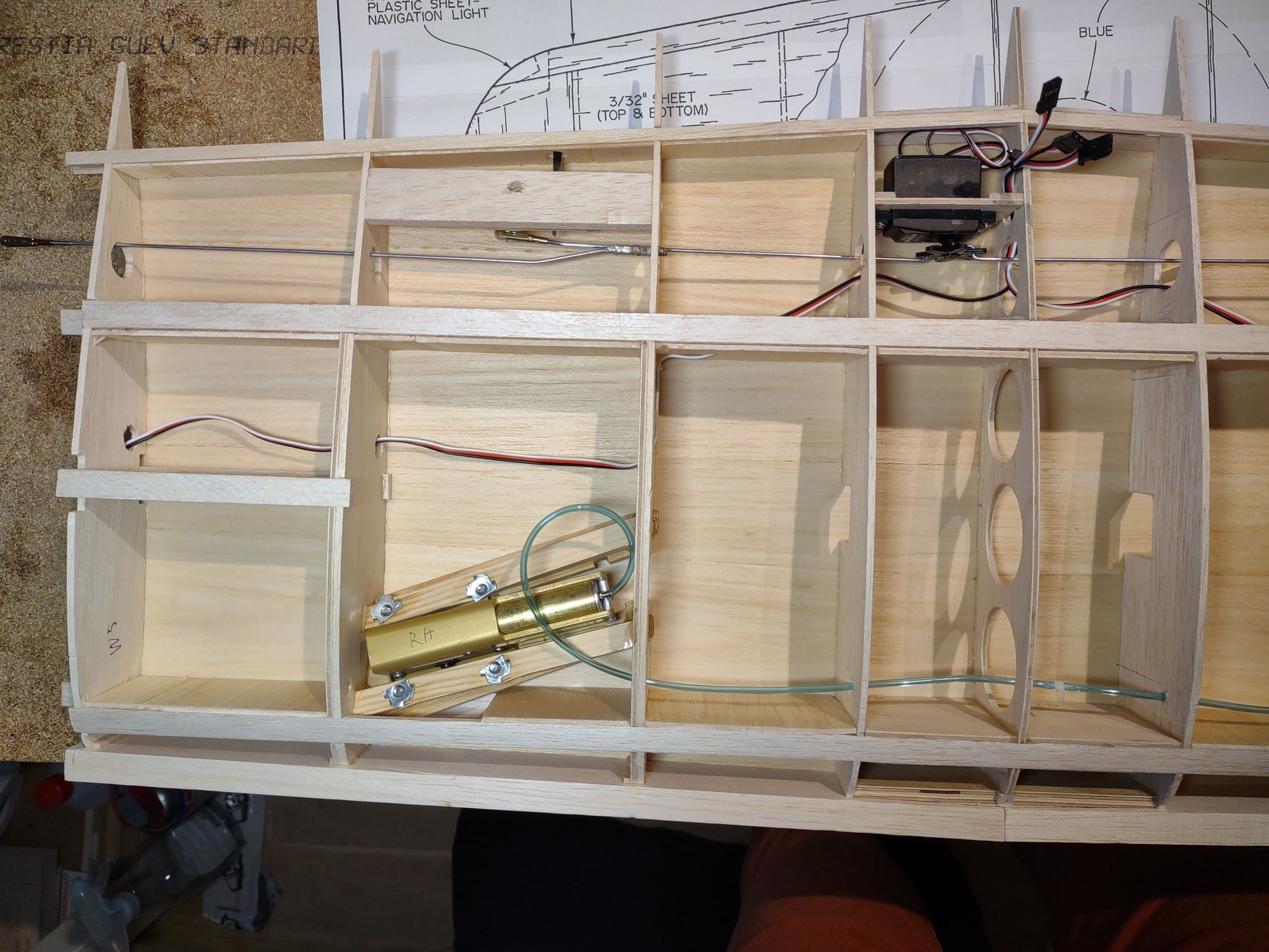
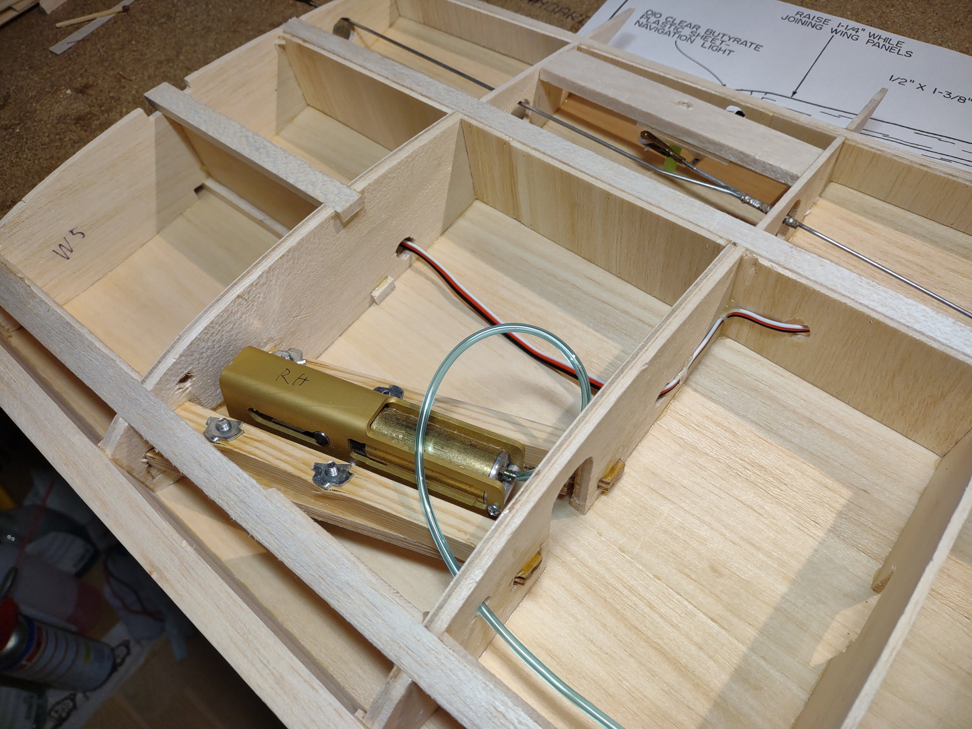
I have to say that I am impressed with the design/plan Anderson made for this plane, but there are some details like this and other I need / have needed to sort out. The retract installation was a chapter on its own where I needed to do a CAD modell of the installation to get the bearers correct, but now sorted well. I created an own thread for that here: Retract advice
If you study the drawing a bit closer, you will see that the building tabs on all ribs except for the W9 builds in no incidence. The washout is only built in between rib W8 and W9, which will cause a very noticeable twist. This is why I do raise questions about this design. I have checked the CAD models of the ribs also, and all of them except W9 has its centerline parallel to the building tabs and flat section on the bottom.
I do plan to built the wing with a 2deg washout distributed from the tip dihedral brace / W5 instead. This will look better and better match common practice. Any reason for not doing it like this?
I have to say that I am impressed with the design/plan Anderson made for this plane, but there are some details like this and other I need / have needed to sort out. The retract installation was a chapter on its own where I needed to do a CAD modell of the installation to get the bearers correct, but now sorted well. I created an own thread for that here: Retract advice
 05-01-2023, 11:10 AM
#7
My Feedback: (60)
Join Date: Dec 2001
Location: Litchfield Park,
AZ
Posts: 7,677
Likes: 0
Received 25 Likes
on
23 Posts
The note on the plan says "Shim 5/32 here while sheeting top surface to produce wash out". I think what he intends for you to do is shim up the tip and introduce a twist into the entire wing panel while applying the top sheeting. So if I am reading the plan correctly it is built upside down on the jig tabs and the bottom sheeting is applied while still on the board. Then the panel is removed from the building board, the tabs are trimmed off, turn the panel right side up and shim it for the wash out, and then apply the top sheeting. Not the way I would have designed it but Mr. Andersen does intend for the wash out to be applied to the full length of the wing panel and not just between ribs 8 and 9.
Last edited by Chad Veich; 05-01-2023 at 11:13 AM.
The following users liked this post:
mgnostic (05-02-2023)
05-02-2023, 07:56 PM
#8
The note on the plan says "Shim 5/32 here while sheeting top surface to produce wash out". I think what he intends for you to do is shim up the tip and introduce a twist into the entire wing panel while applying the top sheeting. So if I am reading the plan correctly it is built upside down on the jig tabs and the bottom sheeting is applied while still on the board. Then the panel is removed from the building board, the tabs are trimmed off, turn the panel right side up and shim it for the wash out, and then apply the top sheeting. Not the way I would have designed it but Mr. Andersen does intend for the wash out to be applied to the full length of the wing panel and not just between ribs 8 and 9.
Trying to show this a little bit on how I have understood this

I have stacked the ribs in my CAD software, aligning them together at the building tabs:
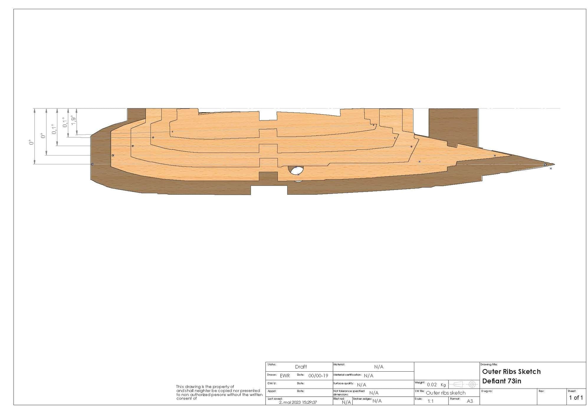
As you can see, all ribs except for W9 are set at 0deg incidence ( models not the best, so a few decimals of on the sketches) when building the wing construction upside down and while sheeting the bottom. Would it then make sense to force this construction out of its relaxed position to create a distributed washout when sheeting the top side? As instructions also says, the wing should be weighted down on the flat side of the ribs when sheeting the top, but the outer rib shall be shimmed 5/32" to create washout at the tip. Looking at the ribs, the flat side on the bottom is also parallel to the centerline / building tabs.
Again, I am questioning the design with washout between rib 8 and 9.
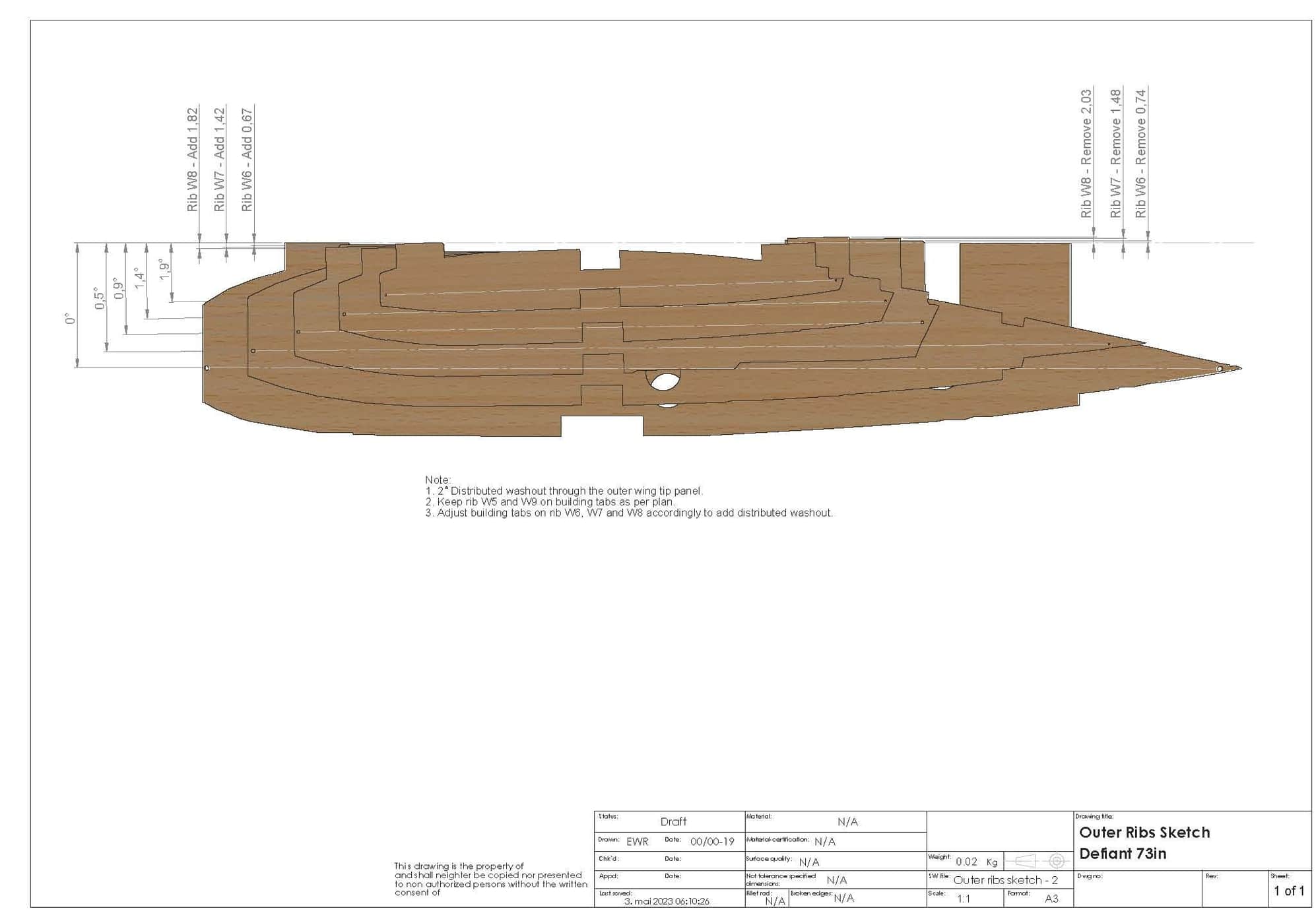
I will adjust the building tabs to make a distributed washout. Cant see anything wrong with this??
Sorry for being a bit direct on this
05-02-2023, 08:18 PM
#9
Here, I have adjusted the ribs for building distributed washout. Will do so. I have to add a Jig / support bracket to the W9 to maintain its position when sheeting the top side. W5 can rest on its flat side when doing this. I ill post my progress 
05-03-2023, 07:40 AM
#10
One of the nice things about CAD is that it gives an opportunity to solve these sorts of design issues. The model doesn't appear to have originally been designed in cad. As good a designer as Mr. Andersen was, errors creep in as plans are drawn, redrawn and copied and assumptions are made in wring articles for magazines. Designers tend to have their habitual ways of doing things. This isn't the first time I have seen a wing that was supposed to be framed up and then twisted before adding one side of the sheeting. Redesigning the ribs should make the washout easier to do and more accurate. It wouldn't be the first time a builder put a bit more polish on a nice design. If it works out well you might upload your rib drawings to the Defiant folder on Outerzone.
05-04-2023, 09:12 PM
#11
One of the nice things about CAD is that it gives an opportunity to solve these sorts of design issues. The model doesn't appear to have originally been designed in cad. As good a designer as Mr. Andersen was, errors creep in as plans are drawn, redrawn and copied and assumptions are made in wring articles for magazines. Designers tend to have their habitual ways of doing things. This isn't the first time I have seen a wing that was supposed to be framed up and then twisted before adding one side of the sheeting. Redesigning the ribs should make the washout easier to do and more accurate. It wouldn't be the first time a builder put a bit more polish on a nice design. If it works out well you might upload your rib drawings to the Defiant folder on Outerzone.
I could absolutely agree with you on this
The CAD system is a very nice tool to solve issues like this. Seems from experience that there are always some modifications needed to get things "right", but this varies widely between each build. Some drawings / kits are very good, but others close to be defined as a "sketch"
To be a scratch build from a downloaded drawing, this one is a good and detailed one, even regarding the issues I have met so far. Adjusting the retract installation was probably the biggest issue, but happy with this so far.I planned to build this plane from another drawing, designed 20 year later to this one. I bought that one together with canopy and gun turret, but sadly it was lacking a lot of scale details compared to the Anderson design.
05-23-2023, 01:30 AM
#12
Hi,
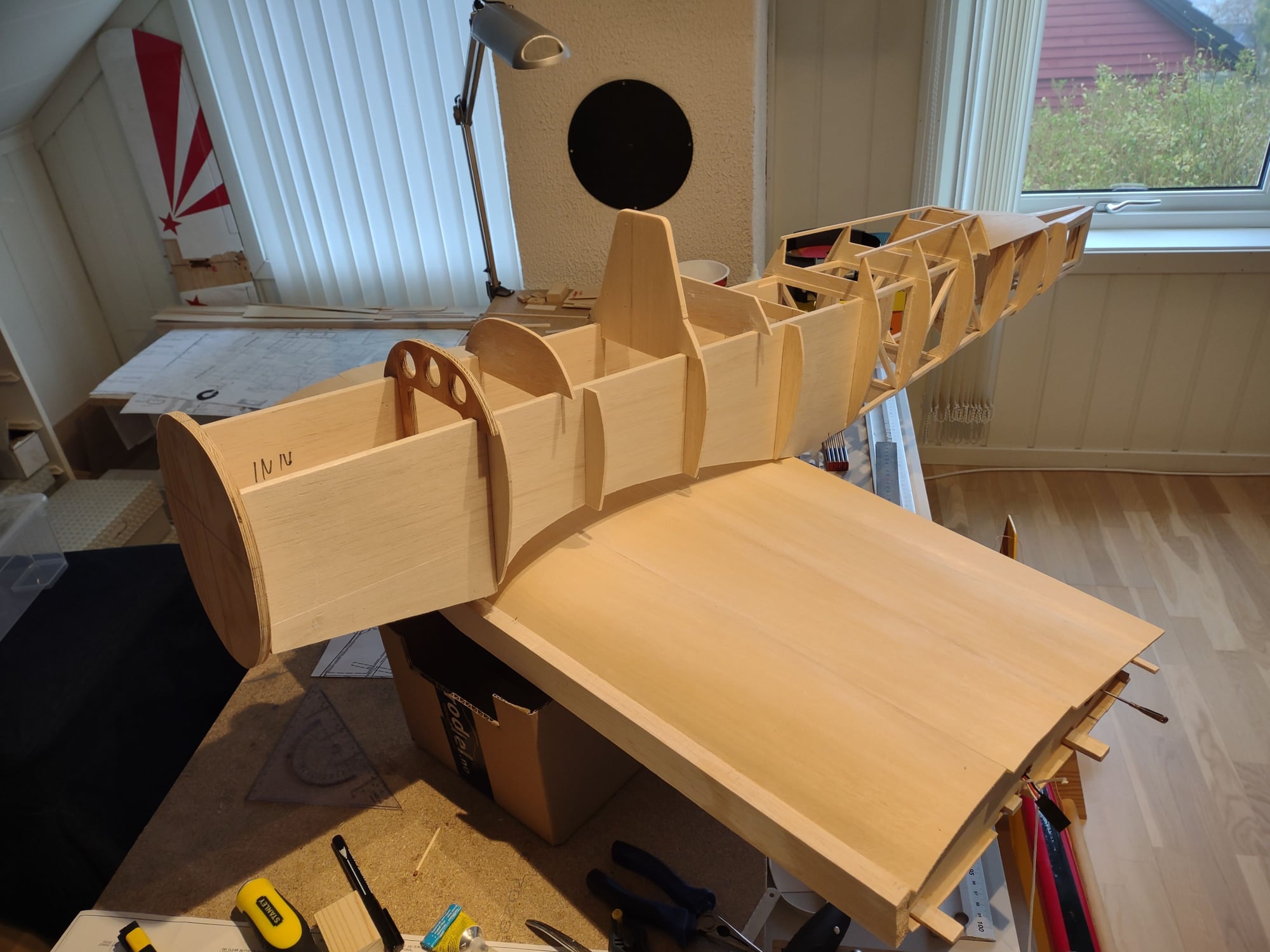
Moving forward slowly. Tabs on the ribs adjusted according to the CAD drawing and basic construction of tips now done. Added shear webs and gussets as it seems reasonable. Not easily seen on the last picture, but a distributed washout can be spotted. Will now continue with the sheeting

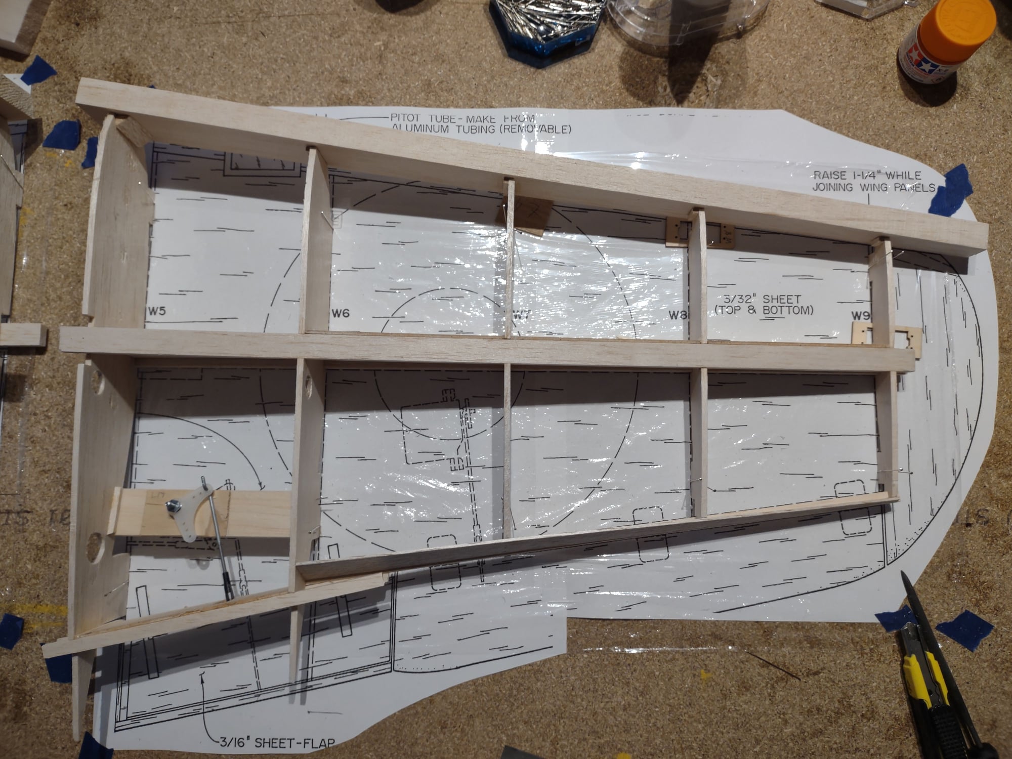
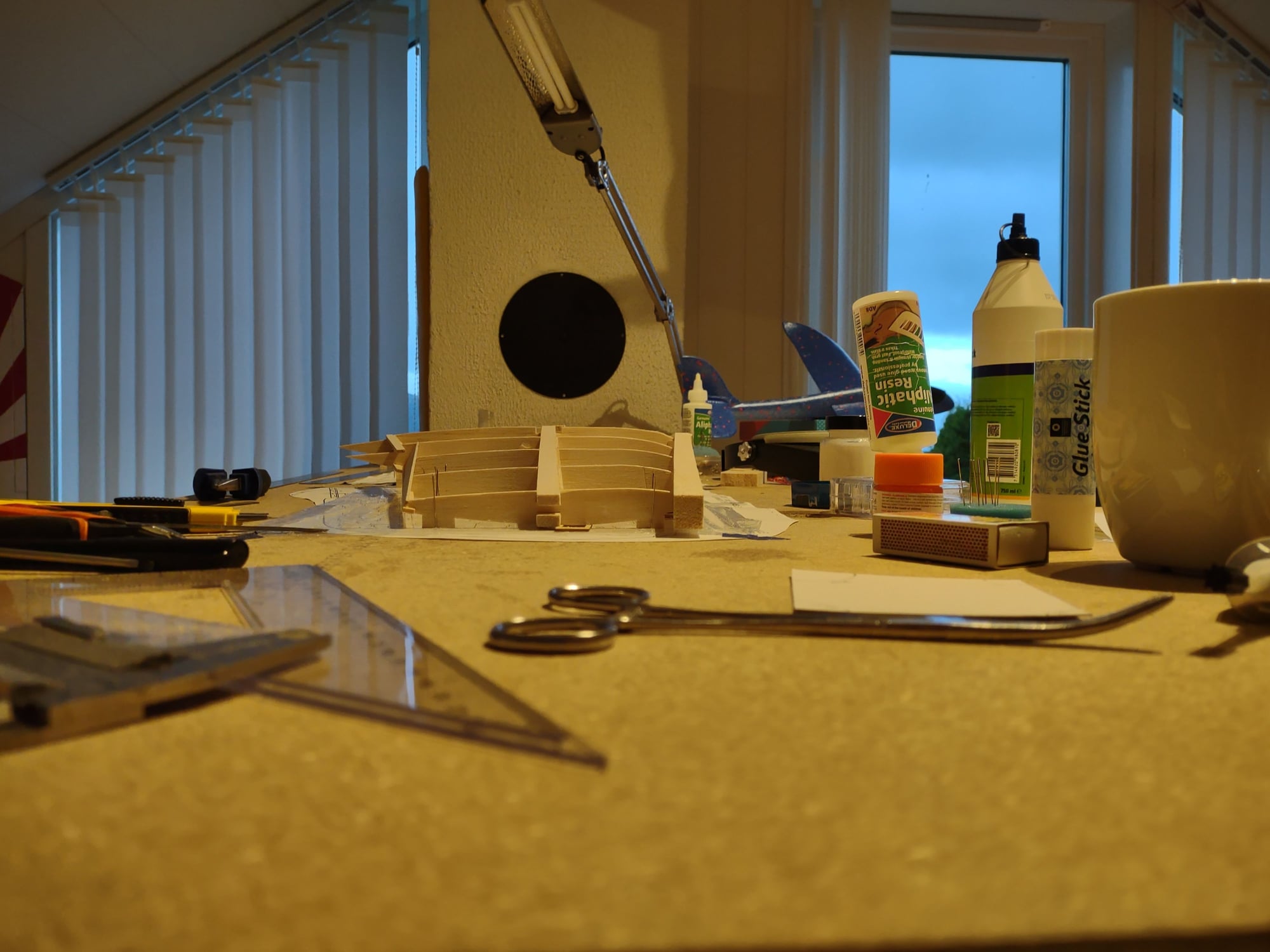
Moving forward slowly. Tabs on the ribs adjusted according to the CAD drawing and basic construction of tips now done. Added shear webs and gussets as it seems reasonable. Not easily seen on the last picture, but a distributed washout can be spotted. Will now continue with the sheeting
08-11-2023, 04:32 PM
#13
Junior Member
Join Date: Apr 2023
Posts: 4
Likes: 0
Received 0 Likes
on
0 Posts
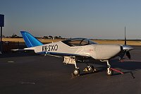
The reason for twisting the wingtip or only having washout at the wing-tips, is at a high angle of attack like during landing, the wing-tips won't stall...and it effects the whole wing very little during regular level flight. They've been doing that on full sized aircraft a long time...on performance oriented aircraft where landing speed is higher.
Here's an example of a small fast aircraft with a twisted wing-tip.
Here's an example of a small fast aircraft with a twisted wing-tip.
Last edited by esaero; 08-11-2023 at 04:41 PM.
08-30-2023, 07:54 AM
#15
Very tidy. Keep up the good work.


