


View Poll Results: Is there any interest to see the large linear servo built from a salvaged printer?
Yes


0
0%


Voters: 1. You may not vote on this poll
Clugh overkill 6mm rudder control arm.
 04-21-2023, 07:27 AM
#1
Banned
Thread Starter
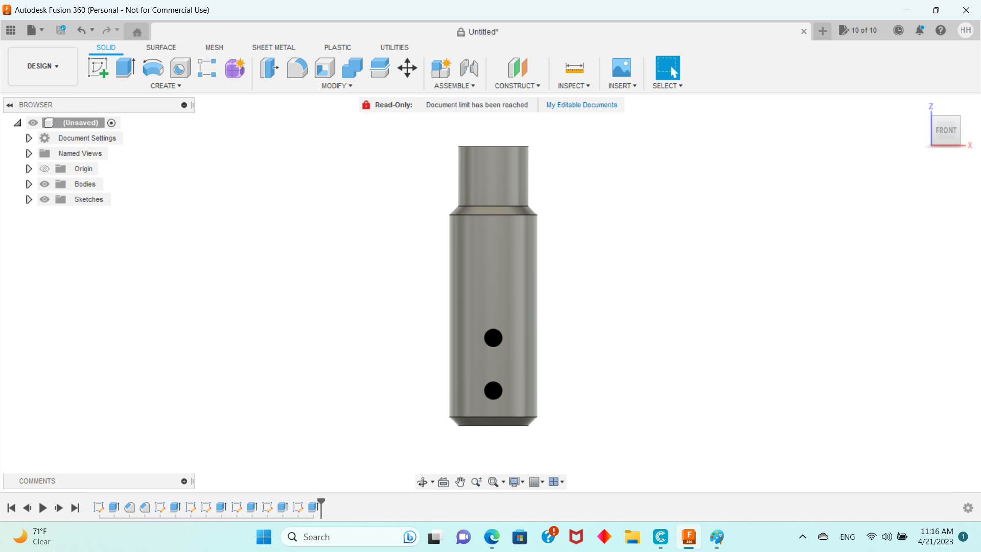
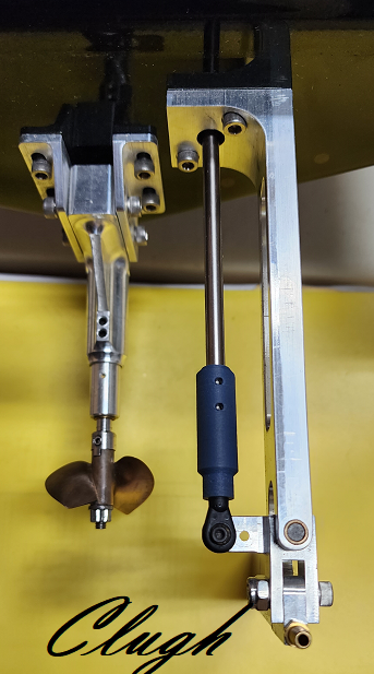
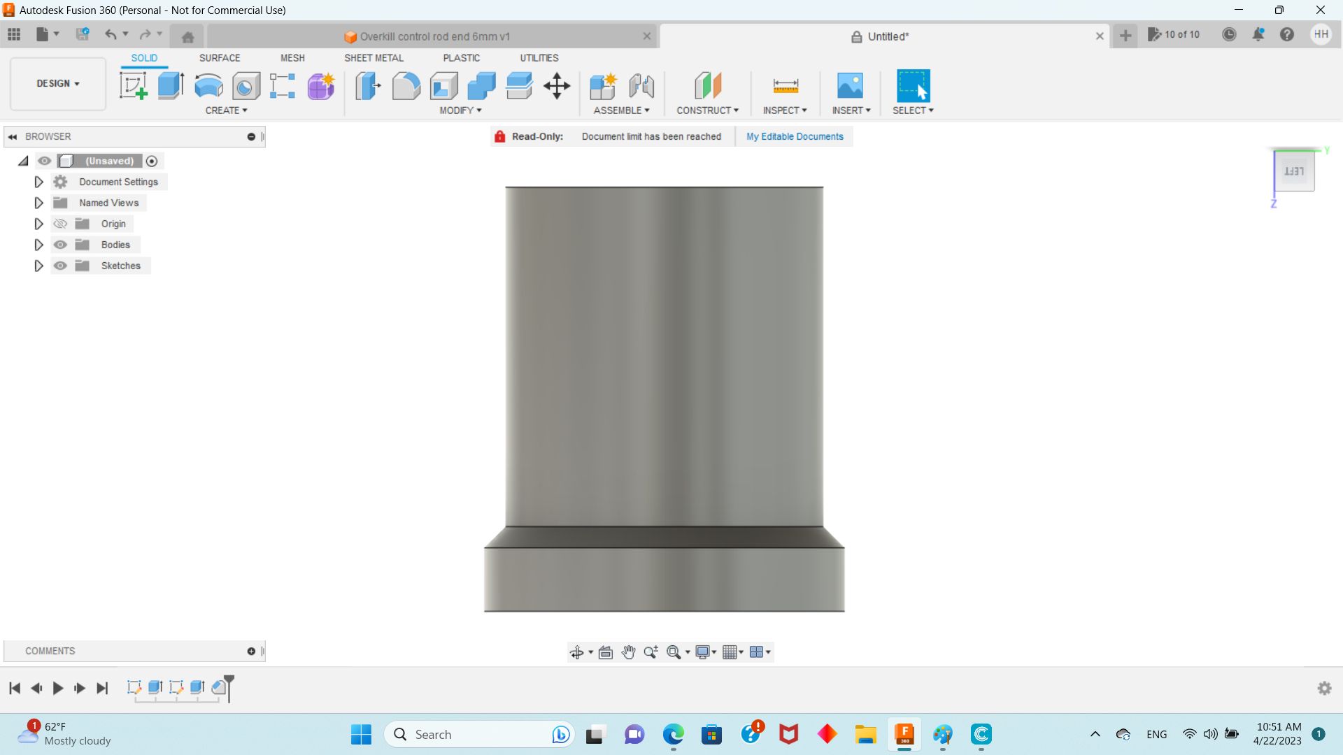
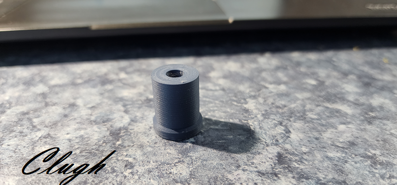
I cant deal with the flex and I do not want a z bend or anything like that so I drew up ends that will achor 3mm ball ends to a 6mm ground shaft I took out of a salvaged printer which has stiff straight ground shafts. The obvious progression would be carbon fiber rod but you can see how it works. The set screw secures the adaptive assembly to the shaft on locking flats ill grind onto the shaft. The 3mm ball end is also aprx 6mm so it glues into an interference fit and 4/40 pre threaded anchors. Lets see how that goes. It will be a straight shaft setup directly to the servo. So I have to slim down the servo tray to put it right on the right rail. I want the rudder rock solid so ill accept the additional weight. If that's what slow me down I have other issues. I think a fluttering prop slows you down even more!

Last edited by Clugh; 04-21-2023 at 07:43 AM.
 04-21-2023, 08:03 AM
#2
Banned
Thread Starter
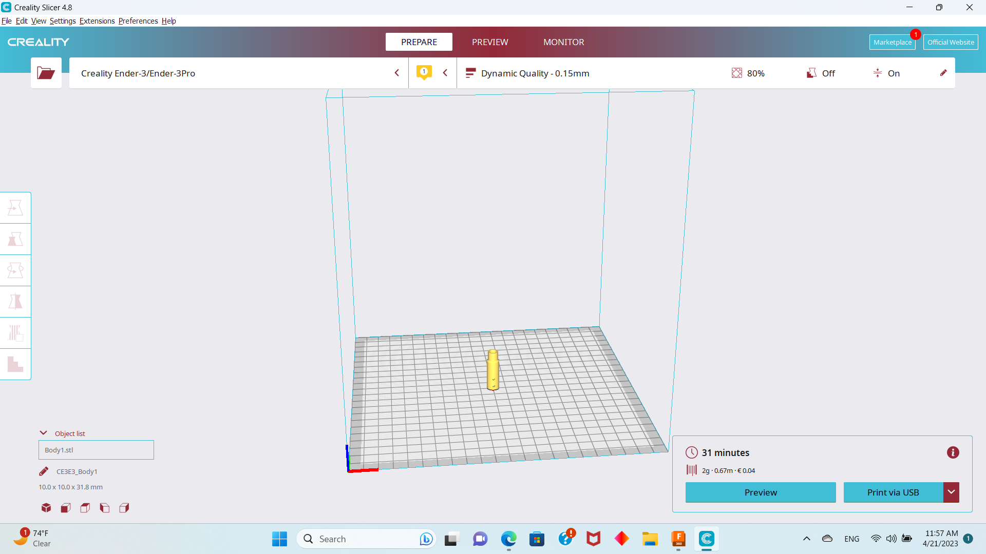
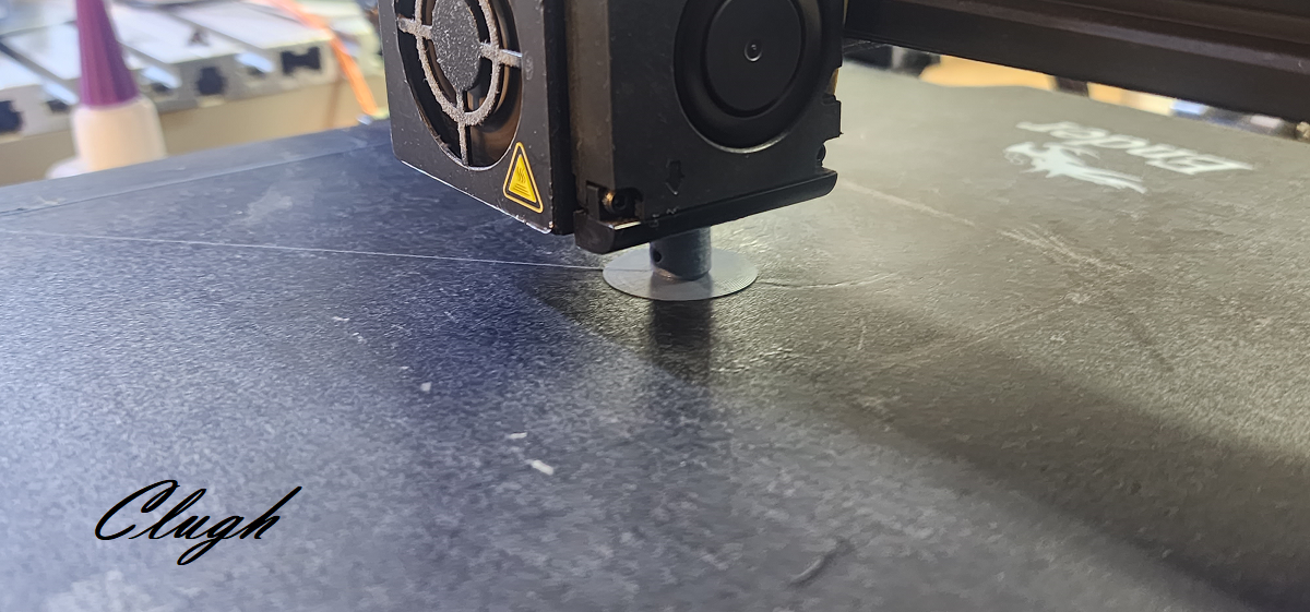
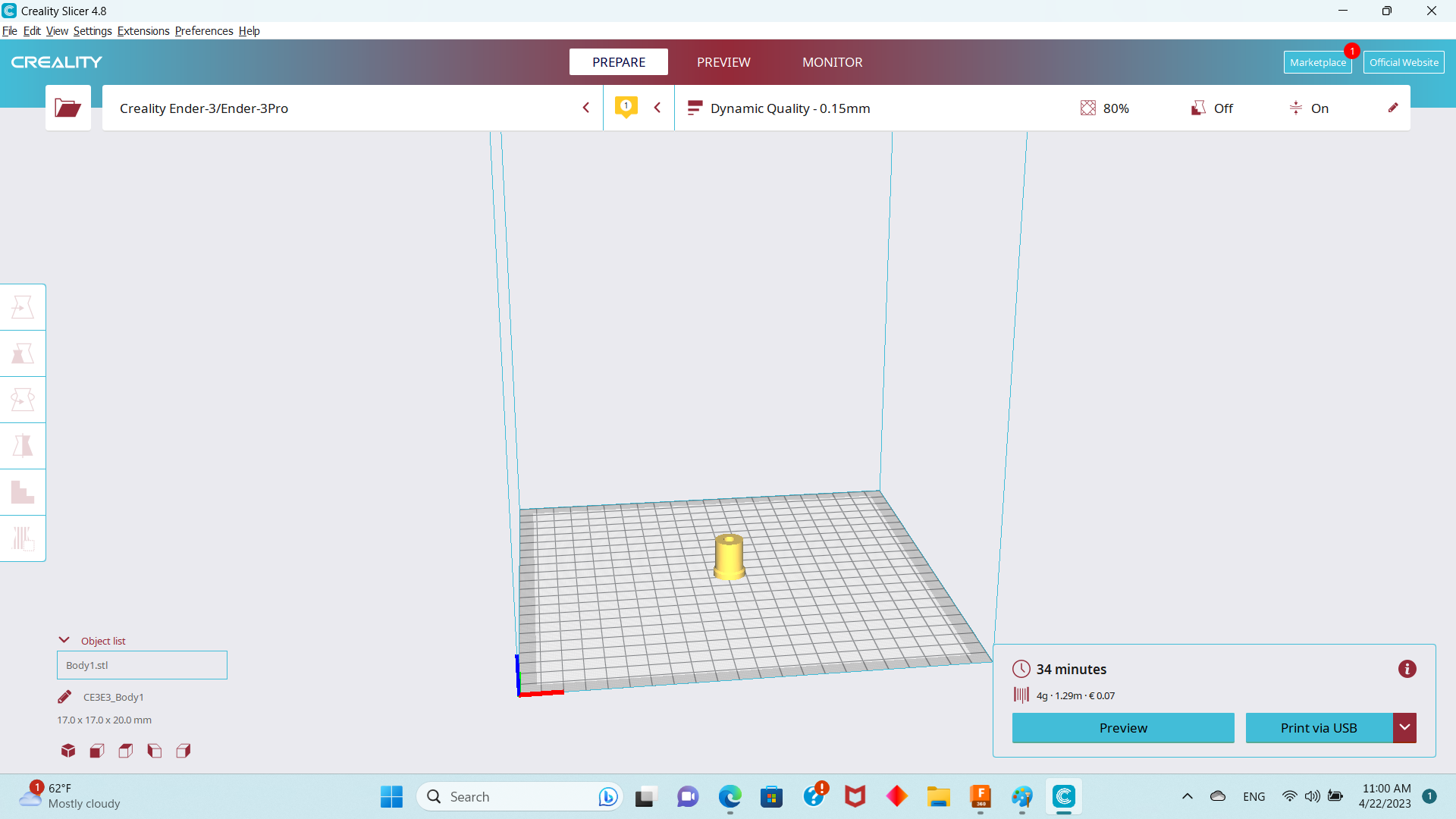
a 30 min print per end.... these will be fine Ill be glad when I get the real deal for faster printing of cf/nylon composite strong as metal with dual head and support materials...
")
Last edited by Clugh; 04-21-2023 at 08:06 AM.
04-21-2023, 08:13 AM
#4
Banned
Thread Starter
For something like this I always use a brim so there something actually bonded to the heating bed to hold it straight. You might even want to slow it down to reduce jerk. That can topple it sometimes if you dont have a good bond to the bed.
04-21-2023, 07:44 PM
#5
Banned
Thread Starter
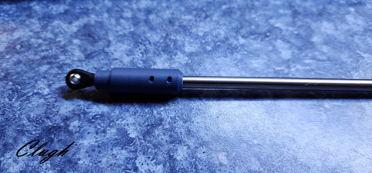
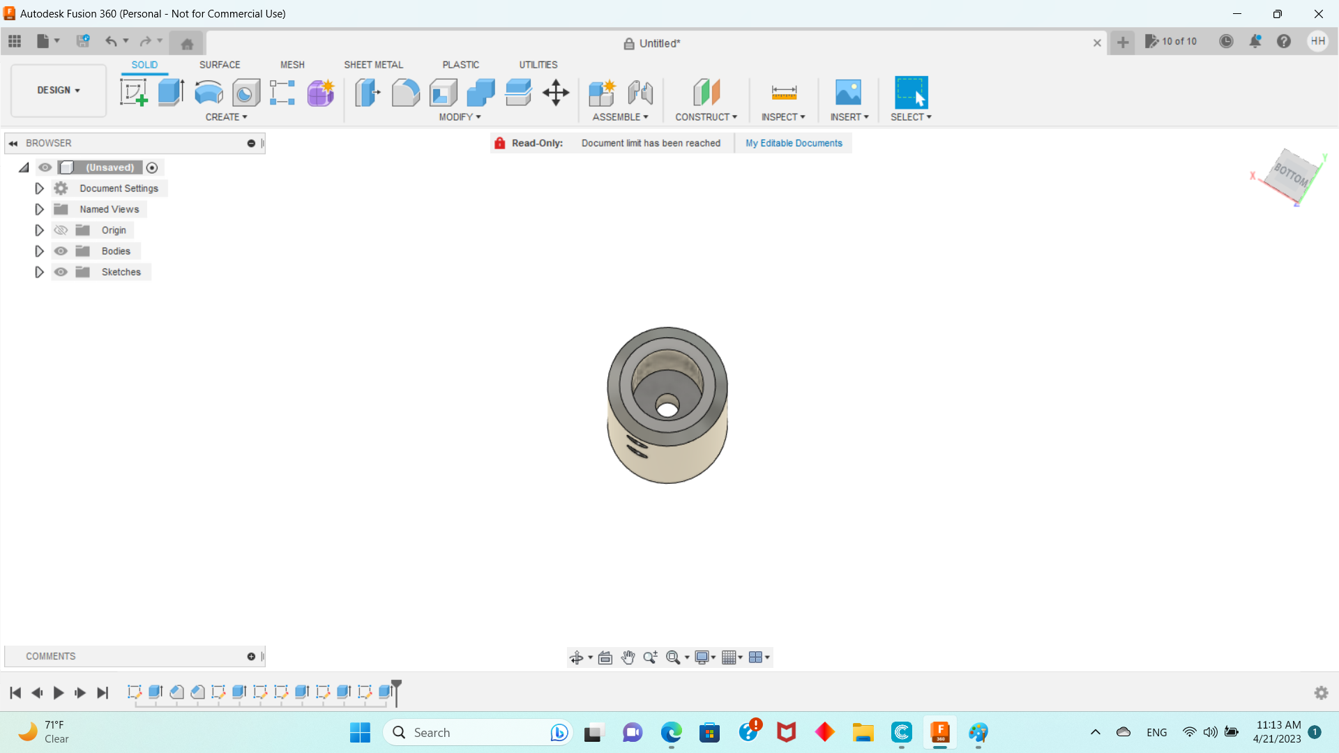
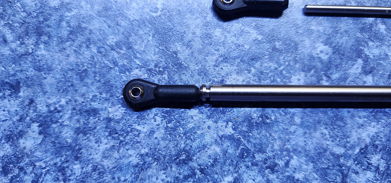
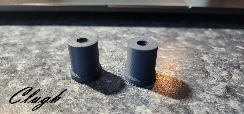
the final version came out nice. I reamed the 6mm shaft side and left the ball end side raw so it is a NICE TIGHT interference fit both ways. Really nice no lies. Ill have to memorialize this one in CF rod and see if the boys are interested. This is a fairly long one and the rudder is not moving unless the servo does and I don't care what side of the boat the rudder is on it does not care!! Ill weigh it when its cut to length. This is going to work really well. I guess i can design a larger ball yoke really and thread the rod. In Cf composite adhesive is strong enough.
Regards,
Hubert
Last edited by Clugh; 04-21-2023 at 07:50 PM.
 04-21-2023, 11:35 PM
#7
Banned
Thread Starter
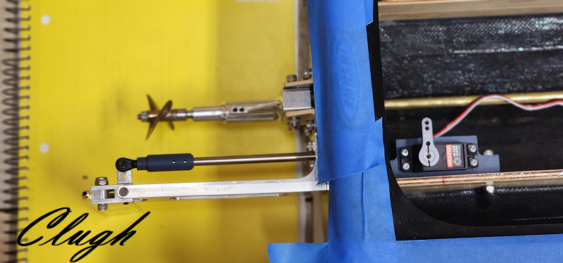
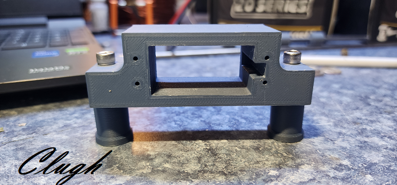
I wont waste the servo tray so ill flip the servo arm and print a spacer plate to get a straight shot to the rudder. That will work out great.
Last edited by Clugh; 04-22-2023 at 03:26 AM.
04-22-2023, 06:45 AM
#8
Banned
Thread Starter
The stand offs need to be about 20 mm with the servo tray. A thick standoff will work and save me material time and weight. So lets see how that goes....

 04-22-2023, 07:18 AM
#12
Banned
Thread Starter
And then I kinda lied to Kevin. Ill show you how this is a great idea but the way Christian has it is with respect to the pivot point is a bad idea. I asked the boys did they know why and no one said a thing so Ill tell you the problem here...
04-22-2023, 07:31 AM
#13
Banned
Thread Starter
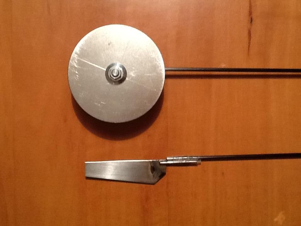
With the rudders pivot point on the axial center of the wheel the leading edge will have a pocket of drag behind the leading edge that probably negates any drag less operation it would otherwise have..
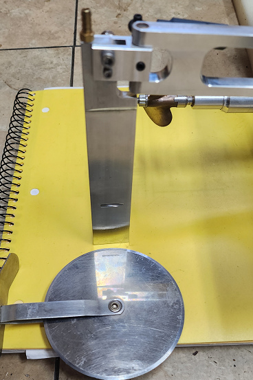
The leading edge of the disk should be aligned at the rudders pivot and the center of the disk needs to be above the water line at speed a real "L" shaped offset split fixture that really makes it work or it is also no good. The wheel needs to be supported on both sides or it is also offset to the pivot point in a detrimental way...
I'd expect more from and ME..

Last edited by Clugh; 04-22-2023 at 07:41 AM.
 04-22-2023, 08:14 AM
#15
Banned
Thread Starter
The good thing about being a degreed Engineer and certified Machinist manual and CNC is that I can draw it and then make the piece. You have to do that part to know if your drawn concepts are feasible to really build and will actually work in the real world. . leaving still photos everywhere doesn't teach anyone anything. I already have plenty of "alpha versions" of PLA in the trash!
Last edited by Clugh; 04-22-2023 at 08:24 AM.
04-22-2023, 08:18 AM
#16
Banned
Thread Starter
Anyone can claim genius but Mr. should build the things he draws and see if it actually works before administering the self congratulating back slaps..
Last edited by Clugh; 04-22-2023 at 08:24 AM.
04-22-2023, 08:31 AM
#17
Banned
Thread Starter
The name shows you how tight I thought we were.

I put him b4 myself. But I don't need him for anything and never did. That was just a courtesy he seems to long for.
The name therefore is an eternal reminder of the level of betrayal you have read on OSE or anywhere else.
I want it clear.
A crayon drawing is a START! But what has he done constructive in the last 24 hours with his own models and motor data but hide to call ME a starter?
Which is an Audiosmith's best impression.

Last edited by Clugh; 04-22-2023 at 08:48 AM.
04-22-2023, 12:31 PM
#19
Banned
Thread Starter
Last edited by Clugh; 04-22-2023 at 12:34 PM.
04-22-2023, 12:39 PM
#20
Banned
Thread Starter
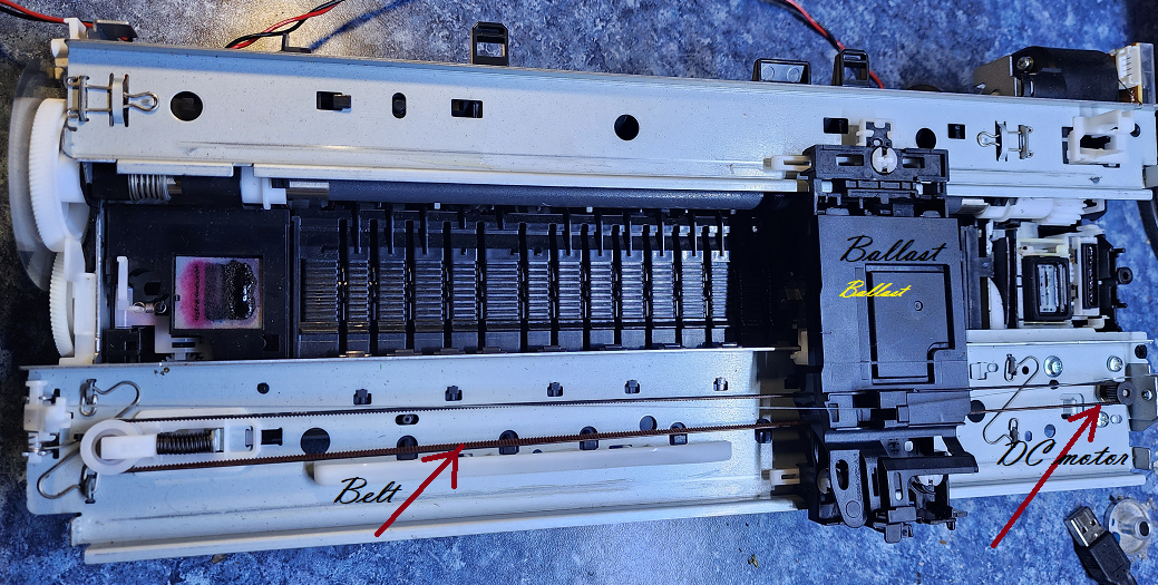
This also gives you the blue print and components to make a purpose built one. Do you understand a "starter"? He certainly can remove the gear reduction from the top of a servo and replace the dc motor with it driving the belts pinion.
Regards,
Hubert
Regards,
Hubert
04-22-2023, 03:59 PM
#21

My Feedback: (10)
The good thing about being a degreed Engineer and certified Machinist manual and CNC is that I can draw it and then make the piece. You have to do that part to know if your drawn concepts are feasible to really build and will actually work in the real world. . leaving still photos everywhere doesn't teach anyone anything. I already have plenty of "alpha versions" of PLA in the trash!
Or even just thread a piece of tubing (stainless, carbon, aluminum, whatever you like) and use a short piece of threaded rod to connect the two.
Not that the 3d printed sleeve won't work, but it doesn't seem like the easiest, cleanest, fastest, or strongest way to do it.
04-22-2023, 05:43 PM
#22
Banned
Thread Starter
Really so you'd turn the 6mm rod down 4/40 thread??and consider that stronger than 12mm diameter PLA overtop of it with a 6 mm high impact nylon insert and the 4/40 also threaded in . That's interesting! Js
Why didn't u help the boys out and build the pushrod for us so we could use i? Plus you don't turn a hardened ground shaft u grind it and pay 10 times the electric bill and no u wont manually machine it faster or with less waste so that's a dream. Silly to fire up a lathe for it .
The ball ends are nylon.
Last edited by Clugh; 04-22-2023 at 06:39 PM.
04-22-2023, 06:31 PM
#24
Banned
Thread Starter
FYI iitz a fact that I dont know any 1/8th scale sailors in WA and no one there knows me. . Im sure you have a friend on the board here in you ear but they truly don't either unfortunately 
If you want to TURN a hardened ground shaft down to size and then THREAD it for 4-40 id say go for it. But im going to stay my course.
Take care.
Going back to my projects.
Thanks for your continued interest.
Hubert

If you want to TURN a hardened ground shaft down to size and then THREAD it for 4-40 id say go for it. But im going to stay my course.
Take care.
Going back to my projects.
Thanks for your continued interest.
Hubert
Last edited by Clugh; 04-22-2023 at 06:49 PM.
04-22-2023, 06:47 PM
#25
My Feedback: (10)
You said it was ground, you never said it was hardened, we were supposed to guess? And if you took it out of a printer, I assume it's just a linear rail, in which case it's only case hardened anyways. It would only take one small (albeit annoying) cut to get below the hardening. If it IS fully hardened, it isn't really the right material for a pushrod in the first place! Besides being way overkill, by using hardened shaft you're now risking breaking as opposed to bending. Of course, at that size, you'd tear the rudder out of the transom before your pushrod bent, so you're not gaining anything anyway.
FYI, I do make my pushrods, but I just use 4mm SS rod and thread it. There's a reason no one makes pushrods like you are here, it's hugely excessive and overly complicated. You're adding weight and complexity with no added benefit.
It's no wonder you're talking to yourself in this sub. Reading a few of your other posts, it sounds like no one wants to listen to your oral diarrhea in person either. Enjoy your echo chamber buddy.