


Lauterbach build.......
 05-08-2014, 01:19 AM
#51

Thread Starter
Join Date: Dec 2003
Location: christchurchnot aplicable, NEW ZEALAND
Posts: 183
Likes: 0
Received 0 Likes
on
0 Posts
Nice, got the engine in and lined up perfect, I cut the carb needles down and slotted the tops again for adjustment ease, this has given me snout 3mm clearance to the top sheeting.
i have started the stuffing box by butting two side walls that when the studding tube is in will get filled with modified epoxy.
seemed like a slow progress evening but happy with the result.
i have started the stuffing box by butting two side walls that when the studding tube is in will get filled with modified epoxy.
seemed like a slow progress evening but happy with the result.

 05-09-2014, 12:40 AM
#53
Thread Starter
Join Date: Dec 2003
Location: christchurchnot aplicable, NEW ZEALAND
Posts: 183
Likes: 0
Received 0 Likes
on
0 Posts
Just a question for the kink folk that may be able to offer some help.
Does anyone know the starting point length fo the pipe I have, it's the zippkits 60mm diameter alloy one.
i kind of need to know the starting point distance for tuning so I cam set up the rear mount and remove a bit of wood from the hull framing for clearances. Cheers
Does anyone know the starting point length fo the pipe I have, it's the zippkits 60mm diameter alloy one.
i kind of need to know the starting point distance for tuning so I cam set up the rear mount and remove a bit of wood from the hull framing for clearances. Cheers
05-09-2014, 02:17 AM
#54
Joe recommends 13 1/2 inches from exhaust port face to center of cone for a starting point for his stainless pipe and adjust in small increments from there. I am not sure about his alloy pipe I would think the alloy pipe should be similar. The best thing to do would be to give him a call or email him. He has very good customer service and is always glad to help a guy out.
05-09-2014, 02:48 AM
#55
Thread Starter
Join Date: Dec 2003
Location: christchurchnot aplicable, NEW ZEALAND
Posts: 183
Likes: 0
Received 0 Likes
on
0 Posts
Joe recommends 13 1/2 inches from exhaust port face to center of cone for a starting point for his stainless pipe and adjust in small increments from there. I am not sure about his alloy pipe I would think the alloy pipe should be similar. The best thing to do would be to give him a call or email him. He has very good customer service and is always glad to help a guy out.
Thanks. I have read his pipe tuning blurb on his site, very good, it did relate to the stainless pipe but I would assume that it is related to the internal reverse cone in the pipe to base the resonating shock wave off. I've sent him a message. Many thanks.
05-09-2014, 04:49 PM
#56
Thread Starter
Join Date: Dec 2003
Location: christchurchnot aplicable, NEW ZEALAND
Posts: 183
Likes: 0
Received 0 Likes
on
0 Posts
I just got an e mail back from Collin at ozrcboats who sell the pipe and he recommends 12" from flange face to fat part of the pipe as a starting point.
05-10-2014, 01:26 PM
#57
Thread Starter
Join Date: Dec 2003
Location: christchurchnot aplicable, NEW ZEALAND
Posts: 183
Likes: 0
Received 0 Likes
on
0 Posts
The donor engine for final dressings, blower and throttle bodies, exhausts, almost too nice to chop. Sponson botton skins going on. And having a play with finishes.
05-11-2014, 01:55 AM
#58
Thread Starter
Join Date: Dec 2003
Location: christchurchnot aplicable, NEW ZEALAND
Posts: 183
Likes: 0
Received 0 Likes
on
0 Posts
Finished the sponsons bottom sheeting today, actually quite a big job, lots of accurate sanding in. I also filled the bottom sheeting joints and put very fine radius in the sponson to botton transitions. Time to put a sealer coat on all the internals now.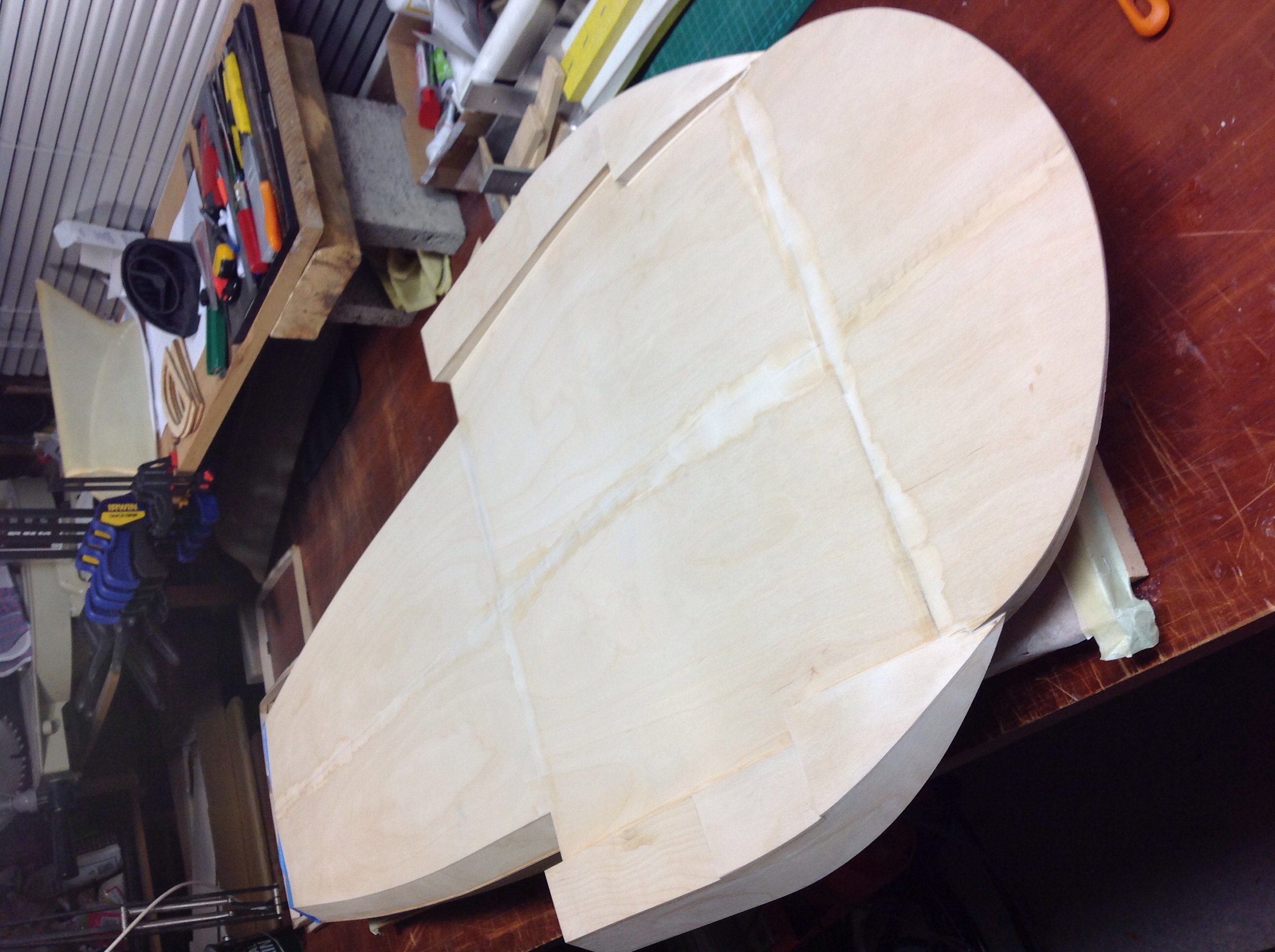

05-11-2014, 11:03 PM
#59
Thread Starter
Join Date: Dec 2003
Location: christchurchnot aplicable, NEW ZEALAND
Posts: 183
Likes: 0
Received 0 Likes
on
0 Posts
Laird up the front engine bay decking this morning and have sealed the internals with a coat of International paints Everdure 2 part epoxy sealer and hardener.
05-12-2014, 12:39 AM
#60
Thread Starter
Join Date: Dec 2003
Location: christchurchnot aplicable, NEW ZEALAND
Posts: 183
Likes: 0
Received 0 Likes
on
0 Posts
A question about shafts.
i have been told that using a Teflon sleeve I will end up with trouble and perhaps a better option is to run the flex straight through the brass outer with a good lube.
so if I go with no Teflon sleeve do I need a smaller diameter brass outer and does the outer go into the front of the strut. At the moment the Teflon sleeve fits into the front of the strut perfect and the solid end of the inner flexi runs through a bearing in the back portion of the strut.
not sure what to do. Cheers
05-12-2014, 02:00 AM
#61
You will want a short piece of 11/32 brass tubing to go through the hull. Secure that in the hull. Then you will need the 5/16 brass tubing to run all the way through the strut and up through the 11/32 tube. That way if you need to you can replace the stuffing tube if need be. I will post a pic and some more detailed info on the brass tubes for you when I get home from work this afternoon.
05-12-2014, 02:28 AM
#62
Thread Starter
Join Date: Dec 2003
Location: christchurchnot aplicable, NEW ZEALAND
Posts: 183
Likes: 0
Received 0 Likes
on
0 Posts
You will want a short piece of 11/32 brass tubing to go through the hull. Secure that in the hull. Then you will need the 5/16 brass tubing to run all the way through the strut and up through the 11/32 tube. That way if you need to you can replace the stuffing tube if need be. I will post a pic and some more detailed info on the brass tubes for you when I get home from work this afternoon.
05-12-2014, 05:22 AM
#63
Junior Member
Join Date: Feb 2013
Location: Canton, MI
Posts: 22
Likes: 0
Received 0 Likes
on
0 Posts
ZEN, You got it. the pic in #62 is correct. I had used the same mock-up engine from Liberty Classics. Most of the real engines turned the blower intake around to keep the water out. For the model, easily done for the scale appearance. I agree, it was a shame to have to use only pieces from such a well done display engine. You have been making excellent progress with the build,and it's going to be very nice when completed.
05-12-2014, 11:53 AM
#64
Sweet got it now, some things take a little longer :-) the brass outer I have is one size too big, I'll get a length if 5/16 which will fit into the strut and some 11/32 for the stuffing box. I never grew up with imperial fractions so use to metric. Can you please confirm my rather rough slap up diagram, cheers
05-12-2014, 11:19 PM
#65
Thread Starter
Join Date: Dec 2003
Location: christchurchnot aplicable, NEW ZEALAND
Posts: 183
Likes: 0
Received 0 Likes
on
0 Posts
Finished the second coat of Everdure and installed the bouyency in the form of nearly 1 whole pood noodle.
Also have the rear decking cover under clamp gluing on the sheeting.
note; I have sealed the sponsons on advise fron another builder to avoid water in them as I can see removal of water would be a right pain.

Also have the rear decking cover under clamp gluing on the sheeting.
note; I have sealed the sponsons on advise fron another builder to avoid water in them as I can see removal of water would be a right pain.
05-12-2014, 11:25 PM
#66
Thread Starter
Join Date: Dec 2003
Location: christchurchnot aplicable, NEW ZEALAND
Posts: 183
Likes: 0
Received 0 Likes
on
0 Posts
Yes you have it right in your drawing. The 5/16 needs to go all the way through the strut until it's flush with the prop side,then your bushing will fit inside the 5/16 tube. You may need to reem your strut with a 5/16 reamer to get the 5/16 brass tubeing to slide in it. I secure the brass tube in the strut with blue locktite. You have to get it in quick because the locktite sets up fast. If you want to remove the tube from the strut just heat the strut with a small propane torch and it will loosen the locktite and you can pull the tube out. You will need to get the thin wall .014 tubeing. don't get the thicker wall or you will not have enough room for the shaft to get proper lubrication. I use the K&S brand tubing. I don't know if you have access to that or not but if you do here are the part numbers for it.5/16 #1151 11/32 #132 Hope this helps. It's looking really good.
05-12-2014, 11:53 PM
#67
Thread Starter
Join Date: Dec 2003
Location: christchurchnot aplicable, NEW ZEALAND
Posts: 183
Likes: 0
Received 0 Likes
on
0 Posts
Another diagram, how does this look? Also the water nipple in the back of the strut, what is it for? Lube, water pick up or water dump.
cheers.
cheers.
05-13-2014, 12:39 AM
#68
Thread Starter
Join Date: Dec 2003
Location: christchurchnot aplicable, NEW ZEALAND
Posts: 183
Likes: 0
Received 0 Likes
on
0 Posts
Having a play with air ducts for carb feed and exhaust venting. I know I can do a nice job of them and I'll practice one on a layup of the exact same wood I'm using, this is a 3 minute job on balsa. I'm pretty sure I'm going to build an air box in the two framing spaces right next to the carb inlet to avoid what has been described as an oven like environment in these hulls when they are running.
I'll have to build the ducts into the top deck sheeting before I glue them down. Any thoughts?
I'll have to build the ducts into the top deck sheeting before I glue them down. Any thoughts?
05-13-2014, 05:51 AM
#69
Junior Member
Join Date: Feb 2013
Location: Canton, MI
Posts: 22
Likes: 0
Received 0 Likes
on
0 Posts
Zen, The air intake ducts, and the airbox, which will provide cool outside air directly to the carb, will work quite well. Closing the sponsons to keep them dry-another good investment. The positive flotation looks adequate. About the strut- The fitting is for lube. suggest before each run, or often. Also about the strut, and the diagram- I would agree with what Madanna has suggested about reaming or drilling the strut,( my method also) so that the brass 5/16 dia. tube goes all the way thru with a replaceable bearing tube inside. Per your diagram; It will work- but only for a short time. Driveline vibration is a big enemy. Even with constant diligence and lubrication. the (factory) bushing wears quickly- typically caused by even slightly out of balance propellers. The resulting vibration threatens the entire driveline to loss or damage. The replaceable tube bearings last a long time and inexpensive to replace- much cheaper than a new stuffing tube, broken/damaged flex cable, new strut, etc. The importance of a well balanced propellor becomes obvious. Two other options for securing the wandering flex cable tube- Near the front opening of the inner and outer tubes. Clamping collar device- similiar to the shaft saver collar, but made to fit the area on the outer tube. Another method; also at the front of the tubes, Add a small (3mm) hole thru only the outer tube. lightly solder one tube to the other thru the hole. Prevents movement, and easily un-soldered. a simple clamp is preferred to allow frequent adjustment of the driveline setup. during those adjustments, the tube moves.Following an adjustment, lock the posotion with the clamp.
Last edited by corky051; 05-14-2014 at 09:36 AM. Reason: more info
05-14-2014, 02:11 AM
#70
Thread Starter
Join Date: Dec 2003
Location: christchurchnot aplicable, NEW ZEALAND
Posts: 183
Likes: 0
Received 0 Likes
on
0 Posts
Zen, The air intake ducts, and the airbox, which will provide cool outside air directly to the carb, will work quite well. Closing the sponsons to keep them dry-another good investment. The positive flotation looks adequate. About the strut- The fitting is for lube. suggest before each run, or often. Also about the strut, and the diagram- I would agree with what Madanna has suggested about reaming or drilling the strut,( my method also) so that the brass 5/16 dia. tube goes all the way thru with a replaceable bearing tube inside. Per your diagram; It will work- but only for a short time. Driveline vibration is a big enemy. Even with constant diligence and lubrication. the (factory) bushing wears quickly- typically caused by even slightly out of balance propellers. The resulting vibration threatens the entire driveline to loss or damage. The replaceable tube bearings last a long time and inexpensive to replace- much cheaper than a new stuffing tube, broken/damaged flex cable, new strut, etc. The importance of a well balanced propellor becomes obvious. Two other options for securing the wandering flex cable tube- Near the front opening of the inner and outer tubes. Clamping collar device- similiar to the shaft saver collar, but made to fit the area on the outer tube. Another method; also at the front of the tubes, Add a small (3mm) hole thru only the outer tube. lightly solder one tube to the other thru the hole. Prevents movement, and easily un-soldered for...
cheers
05-14-2014, 02:39 AM
#71
Thread Starter
Join Date: Dec 2003
Location: christchurchnot aplicable, NEW ZEALAND
Posts: 183
Likes: 0
Received 0 Likes
on
0 Posts
Well I un-clamped the rear deck hatch and sanded it in after work.
I made the decision to sand the veneer with sone 800 grit paper and have gone with a Danska Teak oil for the first topside finish. I have had a pretty good test on a panel I laminated for this very purpose. My topside finish is going to be, 2 coats of Teak oil, 1 coat of Everdure then 3 to 4 coats of Goldspar clear, then all the trim, cowls etc with white single pot Toplac and Red Toplac, all international paints all compatible.
The main reason I have started with the teak oil is to protect the wood from other unwanted staining, fingerprints and general dirt, the raw Tawa veneer is like blotting paper or a white shirt at a red wine party.
I'm pretty happy with the depth of colour the oil has produced which will darken a little more with the final finishing.
With this first bit of the top sheeting done to this stage I'm well happy and can't wait to get the rest of it done.
Any comments on a suitable size tank, which I will get onto soon and ensure it is fitted snug but removable before I cover the for-deck.
i have a Sullivan 12 oz just need to get a fuel proof fittings kit. Do you run the clunk at the back of the tank? I have seen bladder tanks used but have never had any experience with them and I doubt I'll find one here in New Zealand. Cheers
05-14-2014, 08:17 AM
#72
Junior Member
Join Date: Feb 2013
Location: Canton, MI
Posts: 22
Likes: 0
Received 0 Likes
on
0 Posts
Zen, The veneer looks great. really like that color, and the craftsmanship. About the fuel system; First thing- look at the fuel supply nipple on the carb.- approx. 3mm id . fuel hose/tubing, any metal tubes, inline tees or filters, etc. The mentioned id should be maintained for proper fuel supply flow. Zip tie clamps at all connections. Tygon fuel hose for gasoline. Do NOT use any silicone(nitro fuel) hose. The brass tubes thru the stopper plug on the sullivan tank( using 3mm)- likely a problem.The plastic tank requires a vent(good luck with that). My experience with sullivan tanks were cracks, frequent leaks, and other problems. With this hull, and the very limited access under the foredeck, and having to remove the engine for access to the tank- NOT fun. Raw fuel under the foredeck- not good. Hopefully the wood sealers used are gasoline proof (epoxy is). the klunk should be at the lowest part of the tank(gravity assisted)-usually the rear. Adding a lightweight tray to provide a downhill angle and mounting surface works well.
For this hull. the bag system would work much better, if you can get them. Very simple plumbing. No vent required.Durable, predictable and dependable.Easy to maintain and refill with a little practice. Bag can be removed without removing the engine!! An estimate of 15-20 laps around a water soccer field, from either system can be expected for run time. I can provide additional info for a bag setup if requested. After all, it's your boat, your choice, and just my opinion. Cheers.
For this hull. the bag system would work much better, if you can get them. Very simple plumbing. No vent required.Durable, predictable and dependable.Easy to maintain and refill with a little practice. Bag can be removed without removing the engine!! An estimate of 15-20 laps around a water soccer field, from either system can be expected for run time. I can provide additional info for a bag setup if requested. After all, it's your boat, your choice, and just my opinion. Cheers.
Last edited by corky051; 05-14-2014 at 09:24 AM.
05-15-2014, 02:31 AM
#73
Thread Starter
Join Date: Dec 2003
Location: christchurchnot aplicable, NEW ZEALAND
Posts: 183
Likes: 0
Received 0 Likes
on
0 Posts
Zen, The veneer looks great. really like that color, and the craftsmanship. About the fuel system; First thing- look at the fuel supply nipple on the carb.- approx. 3mm id . fuel hose/tubing, any metal tubes, inline tees or filters, etc. The mentioned id should be maintained for proper fuel supply flow. Zip tie clamps at all connections. Tygon fuel hose for gasoline. Do NOT use any silicone(nitro fuel) hose. The brass tubes thru the stopper plug on the sullivan tank( using 3mm)- likely a problem.The plastic tank requires a vent(good luck with that). My experience with sullivan tanks were cracks, frequent leaks, and other problems. With this hull, and the very limited access under the foredeck, and having to remove the engine for access to the tank- NOT fun. Raw fuel under the foredeck- not good. Hopefully the wood sealers used are gasoline proof (epoxy is). the klunk should be at the lowest part of the tank(gravity assisted)-usually the rear. Adding a lightweight tray to provide a downhill angle and mounting surface works well.
For this hull. the bag system would work much better, if you can get them. Very simple plumbing. No vent required.Durable, predictable and dependable.Easy to maintain and refill with a little practice. Bag can be removed without removing the engine!! An estimate of 15-20 laps around a water soccer field, from either system can be expected for run time. I can provide additional info for a bag setup if requested. After all, it's your boat, your choice, and just my opinion. Cheers.
For this hull. the bag system would work much better, if you can get them. Very simple plumbing. No vent required.Durable, predictable and dependable.Easy to maintain and refill with a little practice. Bag can be removed without removing the engine!! An estimate of 15-20 laps around a water soccer field, from either system can be expected for run time. I can provide additional info for a bag setup if requested. After all, it's your boat, your choice, and just my opinion. Cheers.
what size bag do you use? I've found a few on eBay.
i have a 62cc gasser in an extra 300 plane I built so have a reasonable handle on all the required plumbing, tubing etc, thanks for the refresher and info on maintaining the same id for the feed lines, connectors and joiners.
05-15-2014, 02:42 AM
#74
Thread Starter
Join Date: Dec 2003
Location: christchurchnot aplicable, NEW ZEALAND
Posts: 183
Likes: 0
Received 0 Likes
on
0 Posts
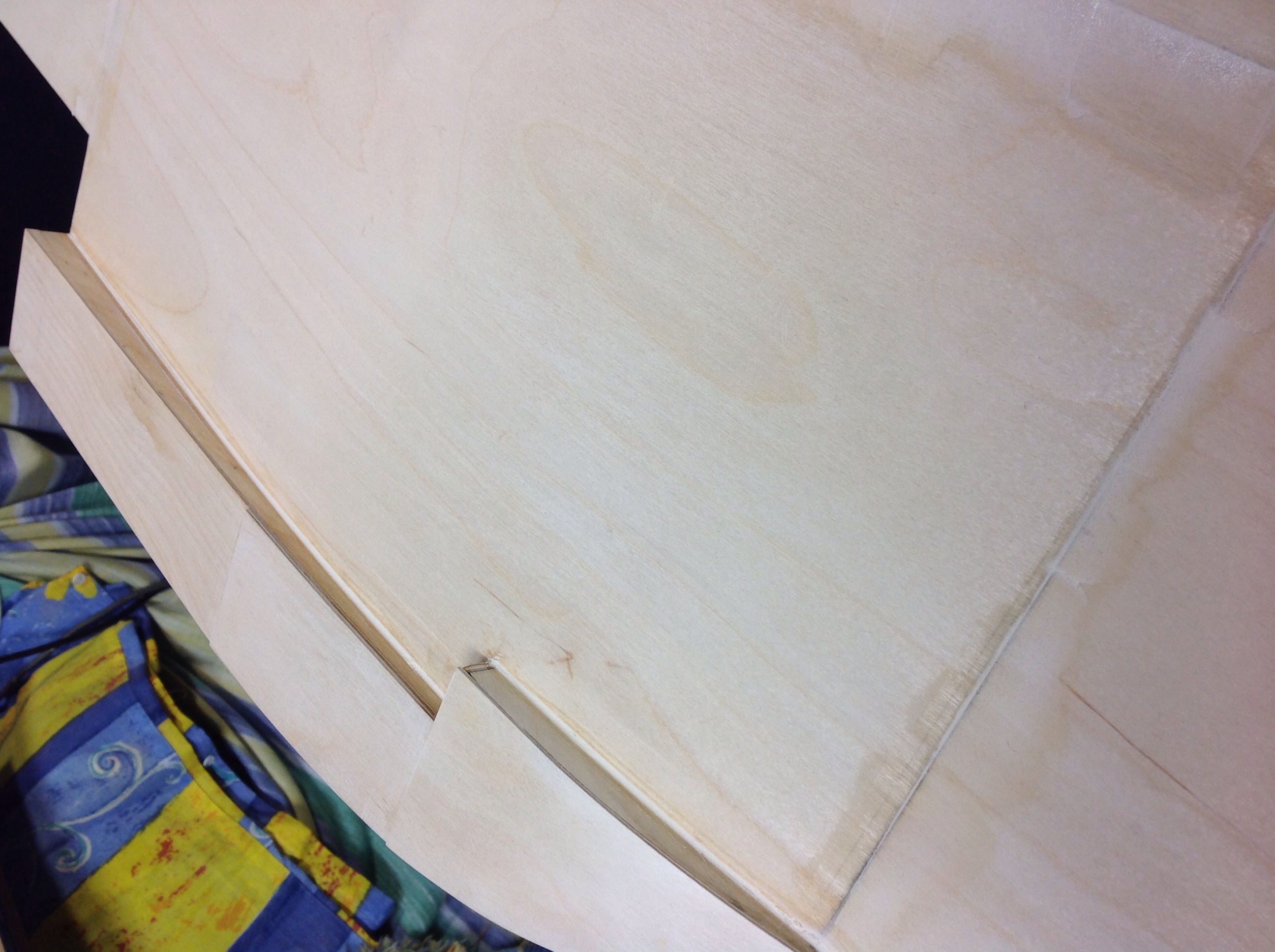
Tonight I decided to go with the air ducts so started on the rear hot air out duct, still a bit of finishing to be done as I'm toying with the idea of trimming them in with a bead of suitable hardwood.
This one took me about 2 hours, call me slow but one slip and I'm laminating up another sheet,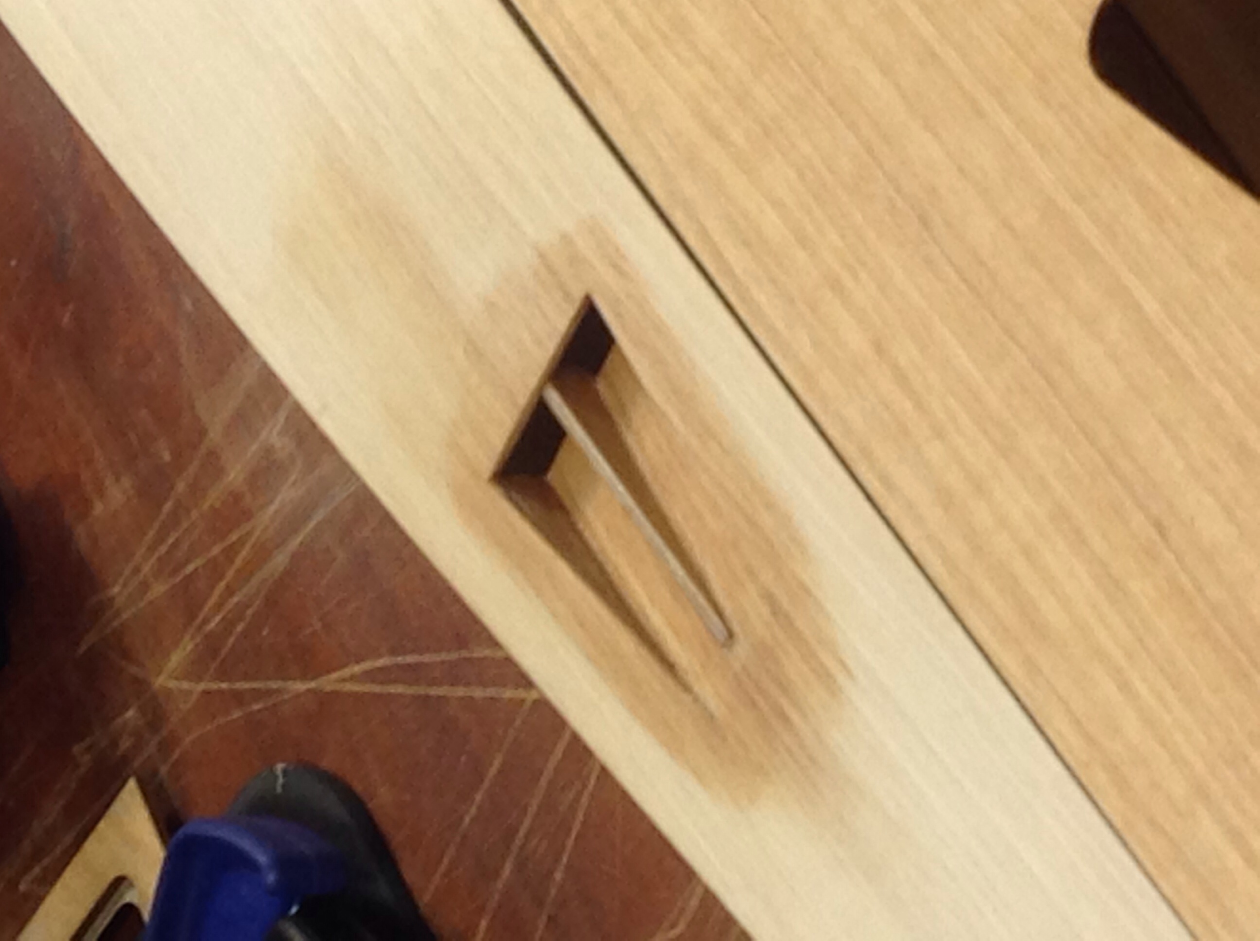 When finished I feel the effort will be well worth it.
This one took me about 2 hours, call me slow but one slip and I'm laminating up another sheet,
Last edited by zen40; 05-18-2014 at 02:55 PM.
05-16-2014, 06:12 AM
#75
Junior Member
Join Date: Feb 2013
Location: Canton, MI
Posts: 22
Likes: 0
Received 0 Likes
on
0 Posts
Hey slow, Nothing wrong with slow. measure twice, cut once. Good things take time. Building this hull takes extra time. Fuel bag - 500ML size/ Baxter brand. I have a few more bits bits of advice. PM sent.

