


HL-Tiger 1: Turret center point
 05-16-2013, 01:30 AM
#1
Senior Member
Thread Starter

Join Date: Sep 2010
Location: Luedenscheid, GERMANY
Posts: 188
Likes: 0
Received 0 Likes
on
0 Posts
Hi guys,
today you are going to correct one of the most important failures of the HL-Tiger.
What´s this failure about?
Well, lets talk about some basics, here.
The turret of the Tiger is shaped like a round tin with a nose at the front.
Normally the center point of the turret is equal to the center point of the "tin".
The center point of the HL-turret is the center point of the hole turret.
That is 13mm to far to the front.
And that we have to correct.
Attention: If you correct this failure, the gun will not be able to shoot 6mm bullets anymore. If you want it to still run, go to the next post when you reach the Word "JUMP" and come back at the word "BACK"
And again, you have two possibilities to solve the problem.
First and easiest one is to buy an adapter. The only one I know about is this one.
www.rcuniverse.com/forum/m_11435924/tm.htm
The one you can see there is an older version. You´ll get the improved one by buying, incl. assembling instructions.
If you choose the hard way, there are some steps to follow first.
1. Open and remove the Tiger tracks
www.rcuniverse.com/forum/m_11502866/anchors_11502866/mpage_1/key_/anchor/tm.htm#11502866
2. Open the Tiger
www.rcuniverse.com/forum/m_11502872/anchors_11502872/mpage_1/key_/anchor/tm.htm#11502872
3. Remove and open the turret
www.rcuniverse.com/forum/m_11503962/anchors_11503962/mpage_1/key_/anchor/tm.htm#11503962
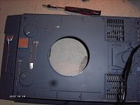
Now lets figure out the correct center of the turret.
Remember, the center point is the center of the "tin".
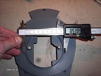
The turret diameter is about 145mm. So the radius is about 72,5mm.
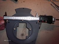
The diameter of the inner ring is about 85mm. So the radius is about 42,5mm.
That is a difference in radius about 30mm. So the edge of the inner ring should be 30mm away from the edges of the turret. Everywhere.
It is ok to the sides but not to the back. There it is 13mm to far a way.
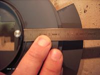
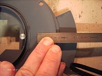
So we have to move the inner ring 13mm to the back. And only to the back.
Lets start.
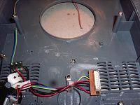
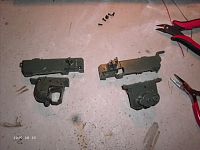
First cut off the two support plates. Remove them carefully. You have to use them again.

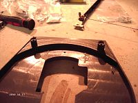
Cut off the inner ring as shown. Do it properly.

Then you position the ring as before and push it 13mm to the back. Mark the new position.

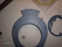
Cut of the marked area. Again properly. Keep the piece for later.
Copy the cut off area to a 1mm poly plate.


Cut off the copied area. Because you need to glue it to the lower turret part, leave a 3mm edge to do so.

Follow the next pictures.


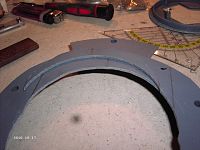
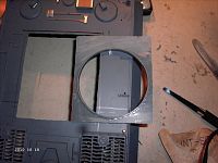
Cut of two areas from the front. The two support plates should fit there. You´ll see later. Glue the poly to the inside of the lower turret.

Glue both cut off turret pieces back to the poly as shown.

After the glue dried, glue the two support plates back to the old position. If you don´t cut off these two areas, the plates will come up to high. So the turret will not close properly.

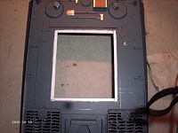
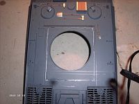
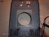
Lets move to the hull, now. Here we also have to move the "big hole" 13mm to the back of the hull.
Because you need some edges to put glue on, you should use the next picture for details."hinten" means back and "vorne" means front.

"Copy" the drawing to the hull.

To figure out the data I had to try a few times. So don´t worry about those many lines. Just copy the ones from the drawing.
Turn around the hull, remove the turning device and all the brackets.

Now cut off the marked area.

Just turning around the piece and glueing back together is not the right thing. Because the ring is not equal in thickness you have to turn it down.
In the next picture you see, what I mean. The top part is thicker then the bottom part. Thats the front. In the back it is the other way round. To keep it like it has to be, turn it down. So the bottom will become the top.
I hope, I made it clear enough. (my english tststststs).

To glue the cut off area back to the hull, use small stripes of poly to create glue edges. They should be 15mm in size. Glue 10mm to the hull and leave 5mm for the area to glue. Not more, because the glue edges of the cut off area are just 5mm wide.
Then glue it back together.
Old position:
Turn down and new position:
To fill up the gaps and make them more stabil, I used 2-component-glue.
The advantage is you don´t even fill up the gaps, but glueing them together twice.
After drying, grind the gaps. In the next picture I grind much more for some other details of my Tiger. Don´t worry about that. Just grind the glued gaps.

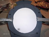
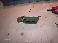
Fill up the back step of the lower turret part with body filler and grind it after drying. This step was necessary, because the turret otherwise would touch some accessories when turning. Now it is useless and even not original.

Now it is time to take care of the gun.
Dismount the gun
"JUMP"
Disassemble the gun. Follow the pictures.


Mount the gun back to the barrel.
"BACK"
Reassemble the turret.
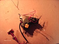
The turret turning device needs a new position. Take double-faced adhesive tape to fix it. Of course you can choose different locations.

Then reassemble the Tiger.
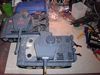
To show you the difference before and after, I took two Tigers for example.
Turret in 12 o´clock position shows no difference.

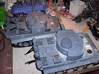
Turret in 9 o´clock position you can see the difference. The lower one is the Tiger we worked on, upper one is an original HL.
If you take a look at the Tigers back, you can see, why the original needs that turret step.
Well, that´s it. Have fun by changing.
Greetings
Birger
For a lot more help with your Heng Long Tiger I tank, follow the below link ...
HL-TIGER I, Basics, Failures and how to remove them.
today you are going to correct one of the most important failures of the HL-Tiger.
What´s this failure about?
Well, lets talk about some basics, here.
The turret of the Tiger is shaped like a round tin with a nose at the front.
Normally the center point of the turret is equal to the center point of the "tin".
The center point of the HL-turret is the center point of the hole turret.
That is 13mm to far to the front.
And that we have to correct.
Attention: If you correct this failure, the gun will not be able to shoot 6mm bullets anymore. If you want it to still run, go to the next post when you reach the Word "JUMP" and come back at the word "BACK"
And again, you have two possibilities to solve the problem.
First and easiest one is to buy an adapter. The only one I know about is this one.
www.rcuniverse.com/forum/m_11435924/tm.htm
The one you can see there is an older version. You´ll get the improved one by buying, incl. assembling instructions.
If you choose the hard way, there are some steps to follow first.
1. Open and remove the Tiger tracks
www.rcuniverse.com/forum/m_11502866/anchors_11502866/mpage_1/key_/anchor/tm.htm#11502866
2. Open the Tiger
www.rcuniverse.com/forum/m_11502872/anchors_11502872/mpage_1/key_/anchor/tm.htm#11502872
3. Remove and open the turret
www.rcuniverse.com/forum/m_11503962/anchors_11503962/mpage_1/key_/anchor/tm.htm#11503962
Now lets figure out the correct center of the turret.
Remember, the center point is the center of the "tin".
The turret diameter is about 145mm. So the radius is about 72,5mm.
The diameter of the inner ring is about 85mm. So the radius is about 42,5mm.
That is a difference in radius about 30mm. So the edge of the inner ring should be 30mm away from the edges of the turret. Everywhere.
It is ok to the sides but not to the back. There it is 13mm to far a way.
So we have to move the inner ring 13mm to the back. And only to the back.
Lets start.
First cut off the two support plates. Remove them carefully. You have to use them again.
Cut off the inner ring as shown. Do it properly.
Then you position the ring as before and push it 13mm to the back. Mark the new position.
Cut of the marked area. Again properly. Keep the piece for later.
Copy the cut off area to a 1mm poly plate.
Cut off the copied area. Because you need to glue it to the lower turret part, leave a 3mm edge to do so.
Follow the next pictures.
Cut of two areas from the front. The two support plates should fit there. You´ll see later. Glue the poly to the inside of the lower turret.
Glue both cut off turret pieces back to the poly as shown.
After the glue dried, glue the two support plates back to the old position. If you don´t cut off these two areas, the plates will come up to high. So the turret will not close properly.
Lets move to the hull, now. Here we also have to move the "big hole" 13mm to the back of the hull.
Because you need some edges to put glue on, you should use the next picture for details."hinten" means back and "vorne" means front.
"Copy" the drawing to the hull.
To figure out the data I had to try a few times. So don´t worry about those many lines. Just copy the ones from the drawing.
Turn around the hull, remove the turning device and all the brackets.
Now cut off the marked area.
Just turning around the piece and glueing back together is not the right thing. Because the ring is not equal in thickness you have to turn it down.
In the next picture you see, what I mean. The top part is thicker then the bottom part. Thats the front. In the back it is the other way round. To keep it like it has to be, turn it down. So the bottom will become the top.
I hope, I made it clear enough. (my english tststststs).
To glue the cut off area back to the hull, use small stripes of poly to create glue edges. They should be 15mm in size. Glue 10mm to the hull and leave 5mm for the area to glue. Not more, because the glue edges of the cut off area are just 5mm wide.
Then glue it back together.
Old position:
Turn down and new position:
To fill up the gaps and make them more stabil, I used 2-component-glue.
The advantage is you don´t even fill up the gaps, but glueing them together twice.
After drying, grind the gaps. In the next picture I grind much more for some other details of my Tiger. Don´t worry about that. Just grind the glued gaps.
Fill up the back step of the lower turret part with body filler and grind it after drying. This step was necessary, because the turret otherwise would touch some accessories when turning. Now it is useless and even not original.
Now it is time to take care of the gun.
Dismount the gun
"JUMP"
Disassemble the gun. Follow the pictures.
Mount the gun back to the barrel.
"BACK"
Reassemble the turret.
The turret turning device needs a new position. Take double-faced adhesive tape to fix it. Of course you can choose different locations.
Then reassemble the Tiger.
To show you the difference before and after, I took two Tigers for example.
Turret in 12 o´clock position shows no difference.
Turret in 9 o´clock position you can see the difference. The lower one is the Tiger we worked on, upper one is an original HL.
If you take a look at the Tigers back, you can see, why the original needs that turret step.
Well, that´s it. Have fun by changing.
Greetings
Birger
For a lot more help with your Heng Long Tiger I tank, follow the below link ...
HL-TIGER I, Basics, Failures and how to remove them.
 05-16-2013, 02:11 AM
#2


Join Date: May 2011
Location: Creixell, SPAIN
Posts: 191
Likes: 0
Received 0 Likes
on
0 Posts
hi again Birger!
yes, it's me again!
i did also this modiffication to my Tiki project, and with some extra work, you can keep the airsoft firing capabilities (go down to theSep 21, 2012 post)
http://www.rctankwarfare.co.uk/forum...p?f=22&t=10148
best regards!
yes, it's me again!
i did also this modiffication to my Tiki project, and with some extra work, you can keep the airsoft firing capabilities (go down to theSep 21, 2012 post)
http://www.rctankwarfare.co.uk/forum...p?f=22&t=10148
best regards!
05-16-2013, 03:57 AM
#3
Join Date: May 2011
Location: Creixell, SPAIN
Posts: 191
Likes: 0
Received 0 Likes
on
0 Posts
hi again, following a Beppel's advice, i will post here the modifications i did in order to keep the firing capabilities of my VS airsoft gearbox (i switched the HL to a VS one)
When i did this turret correction, i moved the center 15mm (2mm too much), but it looks 'almost' ok.
when cutting the inner disk, do not cut the airsoft gearbox supports:


after glueing the parts in the correct order (following Birger's guide), you will notice that the frontal bulb of the gearbox enter in contact with the new layout of the turret's bottom, thus impeding the full elevation of the gun. So i then proceeded to carefully file this part with a rotary tool, after cutting the needed portion of thering support as you can see:

same view, from below:

also, some file has to be done to the turret ring itself:

then moved the turret traverse engine, new supports for the tower's turn engine, made with M2x20 screws


here the turret's bottom already glued and with milluput used to fill the gaps, also note one of the airsoft gearbox supports has been slightly moved and substituted, this was necessary in order to fit the VS airsoft unit


the missing portion of the ring support has no effect on the turret movement and performance
and i think that's all!
best regards
When i did this turret correction, i moved the center 15mm (2mm too much), but it looks 'almost' ok.
when cutting the inner disk, do not cut the airsoft gearbox supports:
after glueing the parts in the correct order (following Birger's guide), you will notice that the frontal bulb of the gearbox enter in contact with the new layout of the turret's bottom, thus impeding the full elevation of the gun. So i then proceeded to carefully file this part with a rotary tool, after cutting the needed portion of thering support as you can see:
same view, from below:
also, some file has to be done to the turret ring itself:
then moved the turret traverse engine, new supports for the tower's turn engine, made with M2x20 screws
here the turret's bottom already glued and with milluput used to fill the gaps, also note one of the airsoft gearbox supports has been slightly moved and substituted, this was necessary in order to fit the VS airsoft unit
the missing portion of the ring support has no effect on the turret movement and performance
and i think that's all!
best regards
05-16-2013, 04:19 AM
#5
Senior Member
Thread Starter
Join Date: Sep 2010
Location: Luedenscheid, GERMANY
Posts: 188
Likes: 0
Received 0 Likes
on
0 Posts
No, it will not. Because the recoil is statik. It doesn´t move up and down with the barrel.
And the brackeds to mount it are not effected from this modification.
Greetings
Birger
And the brackeds to mount it are not effected from this modification.
Greetings
Birger
