


diy cdi
 08-06-2009, 07:39 AM
#1
Member
Thread Starter
Join Date: Jun 2009
Location: Casino, AUSTRALIA
Posts: 40
Likes: 0
Received 0 Likes
on
0 Posts
This thread is for all things related to diy cdi conversions. Circuits, ignition curves 2 and 4 stroke, pictures, links etc.
In the not to distant future I will post some info on an online diy cdi I have just made. I believe it will be very helpful to those considering building it.
I'm also working on a cdi unit with a mate. Early stages yet, will post something when/if its up and working.
I will keep this first post updated with any and all important info. Such as links, circuits, errors and the like.
A few pics of ryobi conversion. Stock, 6600rpm static with 16 x 10 prop.
Dave
 08-06-2009, 10:00 AM
#2
Member
Thread Starter
Join Date: Jun 2009
Location: Casino, AUSTRALIA
Posts: 40
Likes: 0
Received 0 Likes
on
0 Posts
Ignition curves. 2 vs 4 stroke.
The most perplexing questionfor many people is why a 2 stroke has an ignition advance curve totally the reverse of a 4 stroke.
A typical 4 stroke will start with about 10 degrees of advance at idle and finish with around 32 @ peak torque rpm, extending to perhaps 37 @ peak hp rpm. However the advance curve shown below is what will be found in many 2 stroke engines.
The big difference is the 2 stroke suffers terribly from exhaust gas contamination of fuel/air mixture and limited cylinder filling @ lower engine speeds. Therefore the spark plug must fire a comparitively long time before tdc to give the diluted charge time to burn. Then as rpm rise the engine works more efficiently and combustion speeds considerably. The spark advance must be reduced to ensure that the pressure peak from this more rapid combustion accurs past tdc. If it were to peak before tdc or to soon after combustion pressure would rise to quickly and the unburned portion of mixture would explode. It is this uncontrolled burn. detonation, that destroys engines.
Dave
08-07-2009, 08:19 PM
#3
Member
Thread Starter
Join Date: Jun 2009
Location: Casino, AUSTRALIA
Posts: 40
Likes: 0
Received 0 Likes
on
0 Posts
I will dedicate this post to the cdi here: http://www.modelbouw.gompy.net/newcdi/newcdi.htm
With all respect to the designer I feel it necessary to outline some errors I found with this project.
I have built and tested this cdi. Built as outlined it "will not work".
I downloaded all related info for this maybe 8 weeks ago, since then at least one change has been made.
The two biggest errors are the wiring connection for both the sensor and led strobe as shown on the component layout. With these wired as per the diagrams I received the cdi will not work in any mode, test or normal.
Pictures below show sensor connections that have been corrected by designer in last month or so.
+ to -
P to +
- to P
LEDs are polarised and must be orientated correctly. Have a look at both the pcb and component layout. Component layout shows to wire led incorrectly. It puts the kathode or - on the positive 5 volt rail.
Corrections to parts list to follow.
It appears the "last update" on this site is a calender and changes every day. So it might be that nothing on the page is actualy being updated as you would expect.
Dave
08-21-2009, 04:25 PM
#4
Senior Member
Join Date: Dec 2005
Location: Alkmaar, NETHERLANDS
Posts: 548
Likes: 0
Received 0 Likes
on
0 Posts
ORIGINAL: boating around
I will dedicate this post to the cdi here: http://www.modelbouw.gompy.net/newcdi/newcdi.htm
With all respect to the designer I feel it necessary to outline some errors I found with this project.
I have built and tested this cdi. Built as outlined it ''will not work''.
I will dedicate this post to the cdi here: http://www.modelbouw.gompy.net/newcdi/newcdi.htm
With all respect to the designer I feel it necessary to outline some errors I found with this project.
I have built and tested this cdi. Built as outlined it ''will not work''.
Sometimes it is necessary to use your own brains to complete a project.
BUT, WE (the designerS of this hopeless CDI-project) are very curious to your CDI and off ccourse.....is your designe without any errors.
Have a nice day and please, don't awnser or send any mail to us.
08-02-2013, 12:36 AM
#5
Member
Thread Starter
Join Date: Jun 2009
Location: Casino, AUSTRALIA
Posts: 40
Likes: 0
Received 0 Likes
on
0 Posts
well well well
Mates chinese quad broke down and while doing a search a schematic i stumbled by this old thread of mine.
Happy now i didn't return at that time, but now that i'm here.
"If you can't read or relivate schematics, you can't blame the designerS."
Must be able to, did get it working.
"Sometimes it is necessary to use your own brains to complete a project."
I did use my own brain to overcome your errors.
"BUT, WE (the designerS of this hopeless CDI-project) are very curious to your CDI and off ccourse.....is your designe without any errors. "
Maybe, maybe not, you will never know, but i will be man enough to admit to any.
"Have a nice day and please, don't awnser or send any mail to us."
LOL
Have seen your form in more recent threads, including rcgroups, not much has changed apparently.
Now, "to have a nice day" or take my bat and ball and go have a cry.
LOL
08-02-2013, 02:29 AM
#6

Join Date: Mar 2009
Location: xnot applicable, AUSTRALIA
Posts: 293
Likes: 0
Received 0 Likes
on
0 Posts
I think you will find the system used a 16F628A pic chip and it never really ever worked successfully.
It was a good idea basically and the supporting software to upgrade the curve worked nicely.
Connect all but the power section and all worked beautifully.
Connect the power section and a spark plug and down it would go.
Many tried and contributed a lot but there was a basic flaw somewhere in the software(as far as anyone could make out) for which the source was never released.
Apparently written by a third party somewhere (anon).
Problem most had was the chip would lock up, sometimes the program would become unusable and one had to re-program while at other times the chip would never recover.
John's little 12F683 system came along and worked great so the former was abandoned.
The latter has now been modified and rewritten and run in a 12F1840 with telemetry system yet to come.
08-28-2013, 06:14 AM
#7
Member

Join Date: Jul 2013
Location: near Malone, NY
Posts: 35
Likes: 0
Received 0 Likes
on
0 Posts
The problem with micro-controllers is their sensitivity to RF noise. I was using an Arduino board under a florescent desk lamp and it kept locking up which I had never seen before. I initially thought that I had cooked the board somehow. With the desk light off it worked just fine.
I test automotive ignition systems and they generate quite a bit of RF noise, can't say I surprised that they had trouble running a MC next to an ignition coil.
With the new Coil on plug setups you can get the coil far away from the controller and it should be easier to implement. Add some RF filtering and maybe an opto-isolator and it should be just about bullet proof.
I've got a "homebrew" CDI setup that I'm testing now using a standard magnetic pickup instead of a hall switch. I find the halls are too sensitive.
08-30-2013, 05:20 AM
#8
Join Date: Mar 2009
Location: xnot applicable, AUSTRALIA
Posts: 293
Likes: 0
Received 0 Likes
on
0 Posts
The 12F683 never had any interference problems and neither did the latter 12F1840.
It was identified though that the 16F628A was too sensitive for ignition systems.
I use the Alegro uA1340 Halls for above 12F683 and 12F1840 without any problem.
Sensitivity can be high using too large a magnet.
It was identified though that the 16F628A was too sensitive for ignition systems.
I use the Alegro uA1340 Halls for above 12F683 and 12F1840 without any problem.
Sensitivity can be high using too large a magnet.
Last edited by bluejets; 08-30-2013 at 05:35 AM.
09-01-2013, 06:11 PM
#9
Member
Join Date: Jul 2013
Location: near Malone, NY
Posts: 35
Likes: 0
Received 0 Likes
on
0 Posts
Here is my take on the diy cd ignition setup using some cots parts and a 25cc homie.
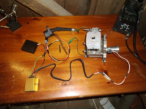

I'm using a RPT C-500 coil and a VW electronic ignition conversion module with magnetic coil pickup.
Crank magnet is pressed into the original flywheel after cutting it down to minimum diameter.
I still need to get a short plug wire and remove the original C-500 rubber boot.
Works well with 4 -AA batteries.
Correction: 4 AA alkaline batteries work for a little while, switched over to 3S Li-Po, works better Found better unit at work update more later.
Last edited by propellantchem; 09-09-2013 at 06:16 AM.
