


1959 Berkeley Impulse Build
 02-16-2014, 08:46 PM
#1

Thread Starter

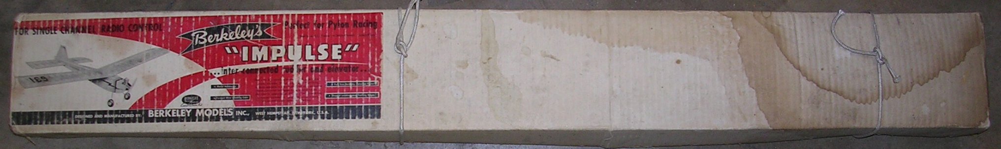
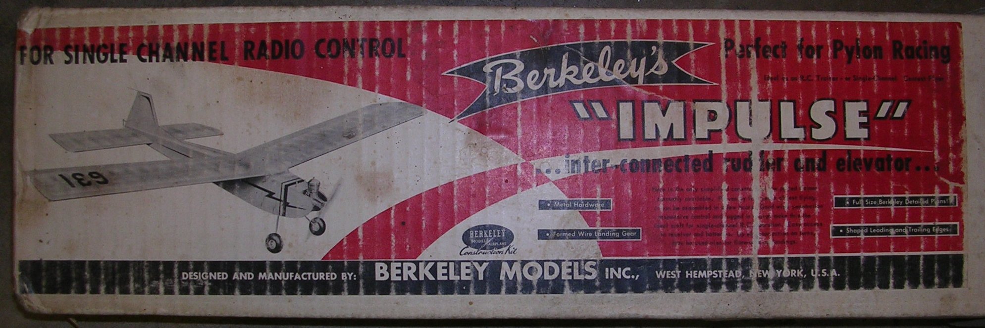
Several years ago, I bid and won an original Berkeley Impulse kit on E-Bay. I don't remember exactly how much I paid for it, but I think it was around $40 shipping included. The kit had some water stains on it. The plan was aged from heat. It appeared the kit had been stored in someone's attic for a while.


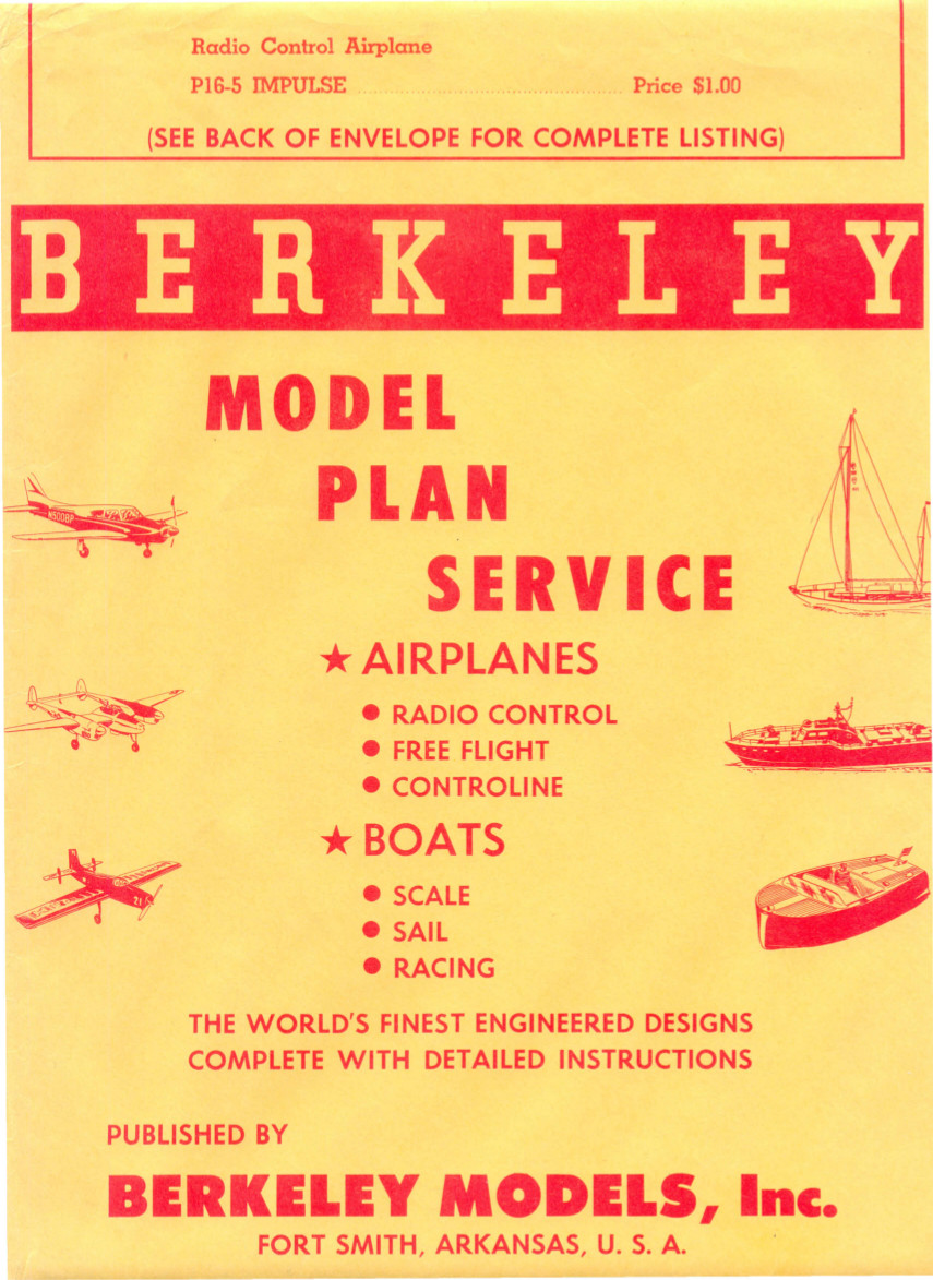
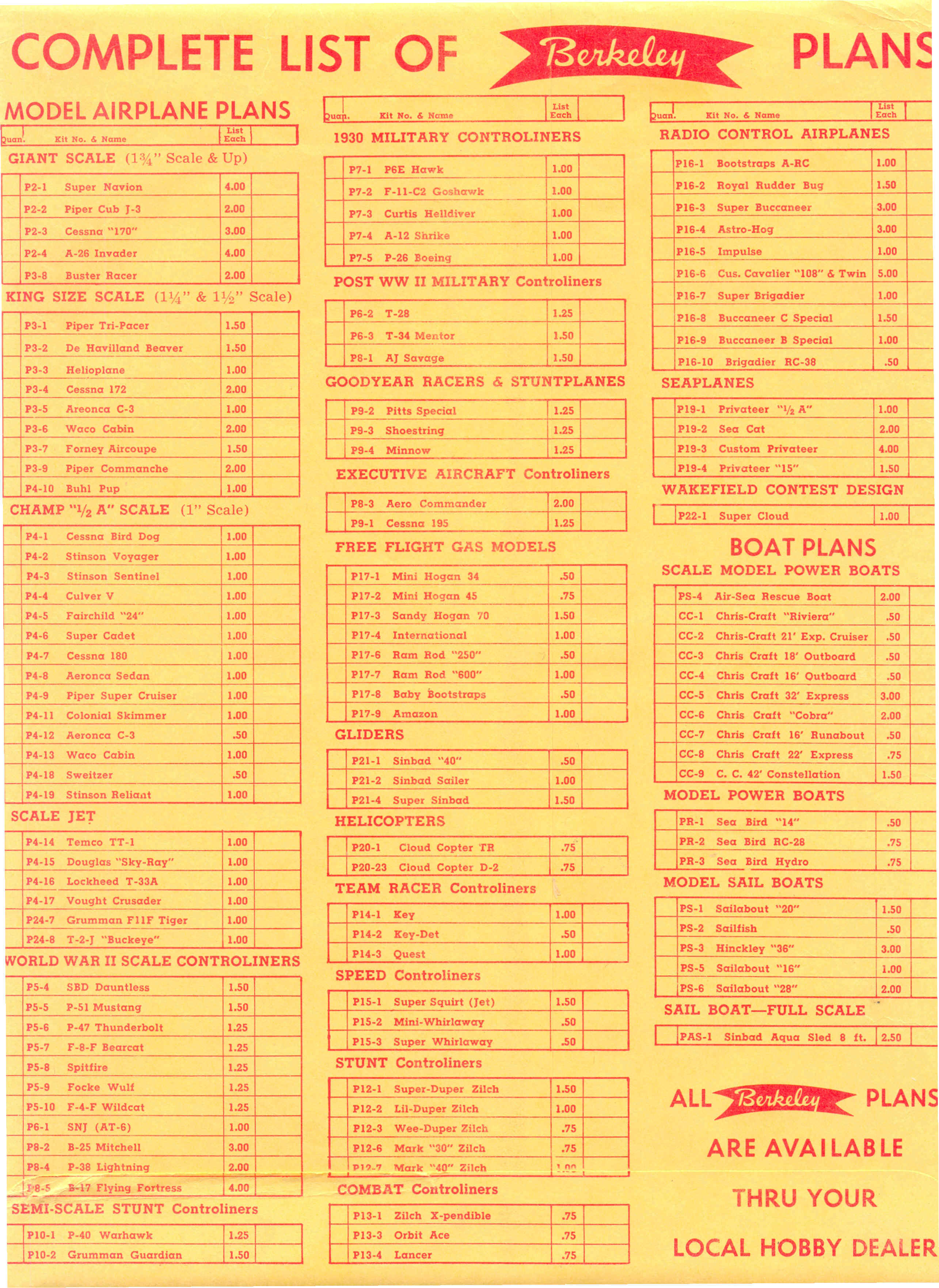
First, I reconnoitered the situation. I already had a good plan that I bought from Sig in the mid 1990's, when they were clearing out the remaining Berkeley plans they had in stock. It came with the original Berkeley plan envelope. As Kit P16-5 it sold for $1.00 US when Berkeley was still in business in the early 1960's. Of course I paid more for it from Sig, but it was still only a couple bucks.
First impressions of the kit .... it had a lot of die crunched pieces and plywood was the inferior quality Luan, not birch ply of later kits. Accuracy of die cutting left a little to be desired on larger pieces such as the fuselage halves.
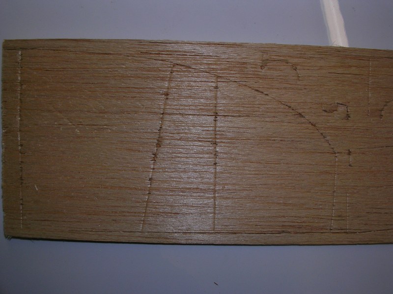
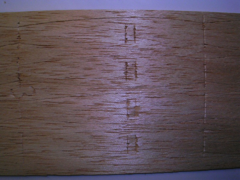
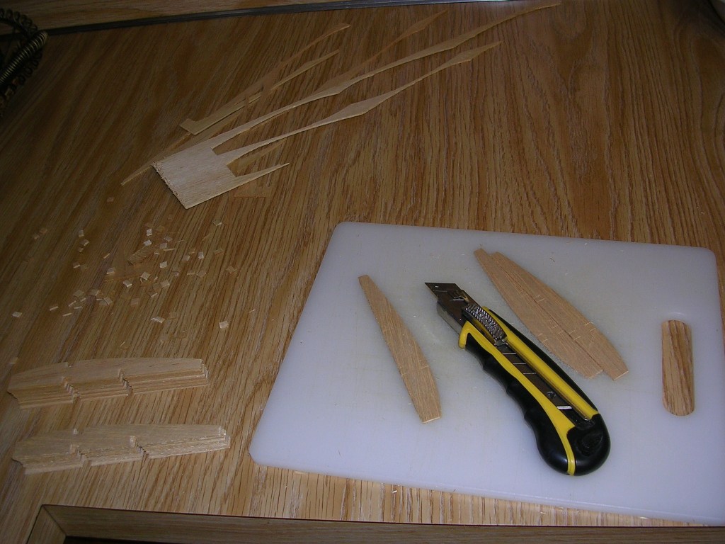
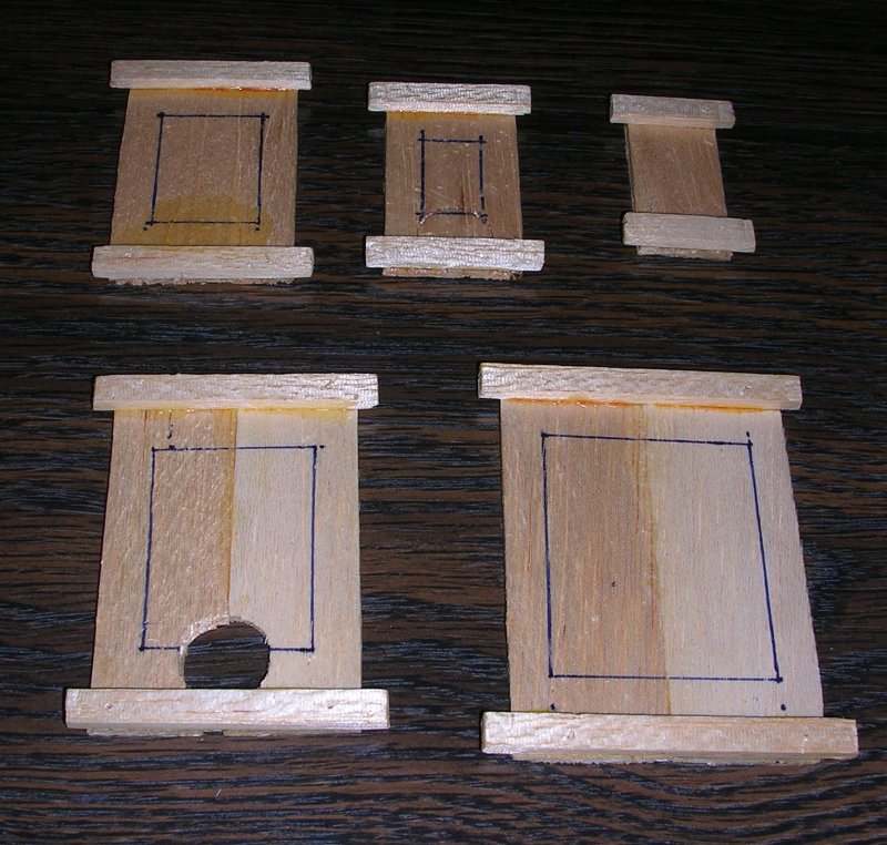
First, I started off by cutting out the wing and stabilizer ribs, fuselage sides and formers, then start assembly.
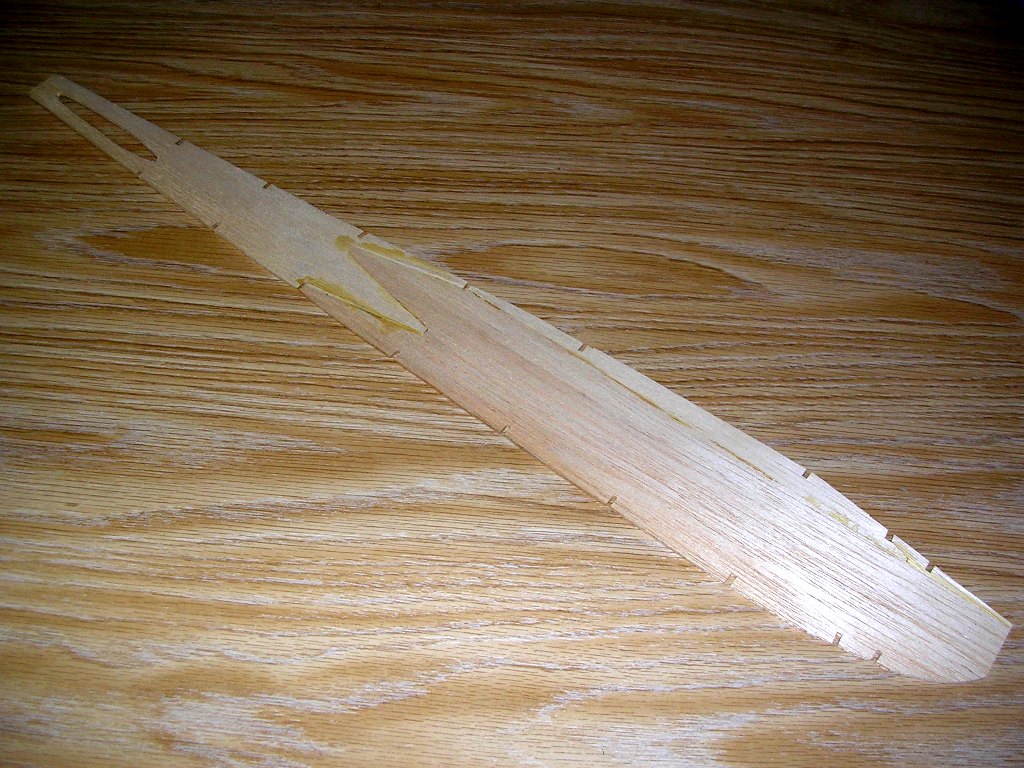
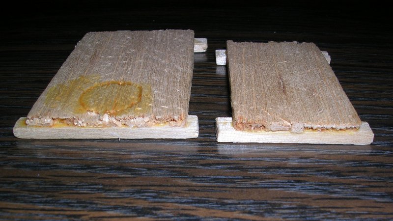
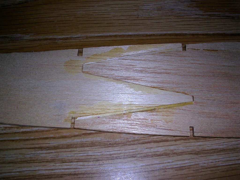
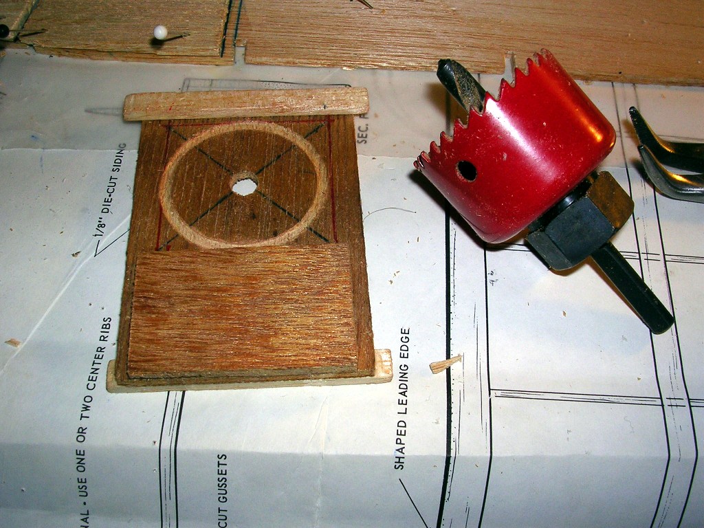
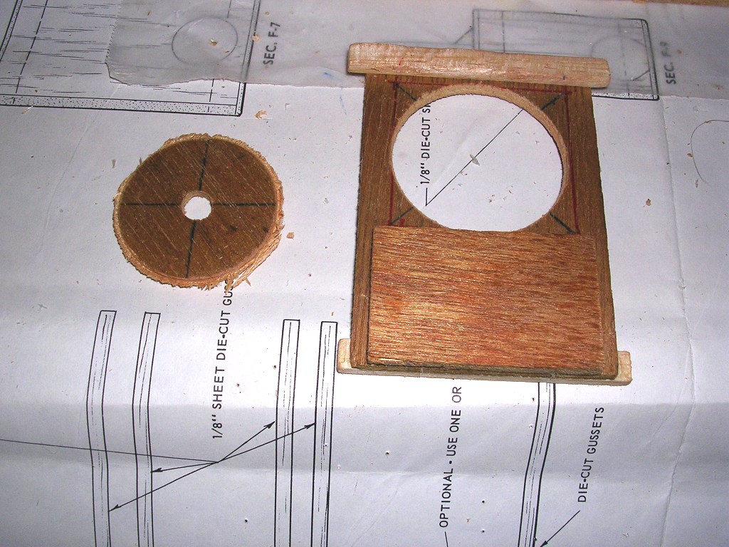
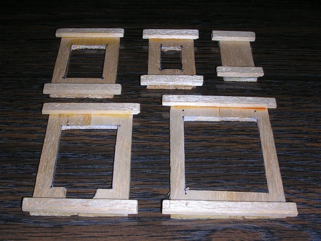
Fit and finish of the fuselage sides were rough. I trimmed as best as possible, but still fell short, ended up splicing a little back to make a solid fuselage side from two pieces. Then pieced together the buikheads. Also removed balsa from the center of the bulkheads to reduce weight. To make room for the fuel tank, I cut out the center of the landing gear mounting bulkhead with a hole saw. To prevent from splitting the Luan, I rotated the bit manually by hand until I penetrated the first ply on the front side, then the back. Then chucked the bit in a hand held electric drill and finished the hole. This resulted in a clean hole in the Luan.
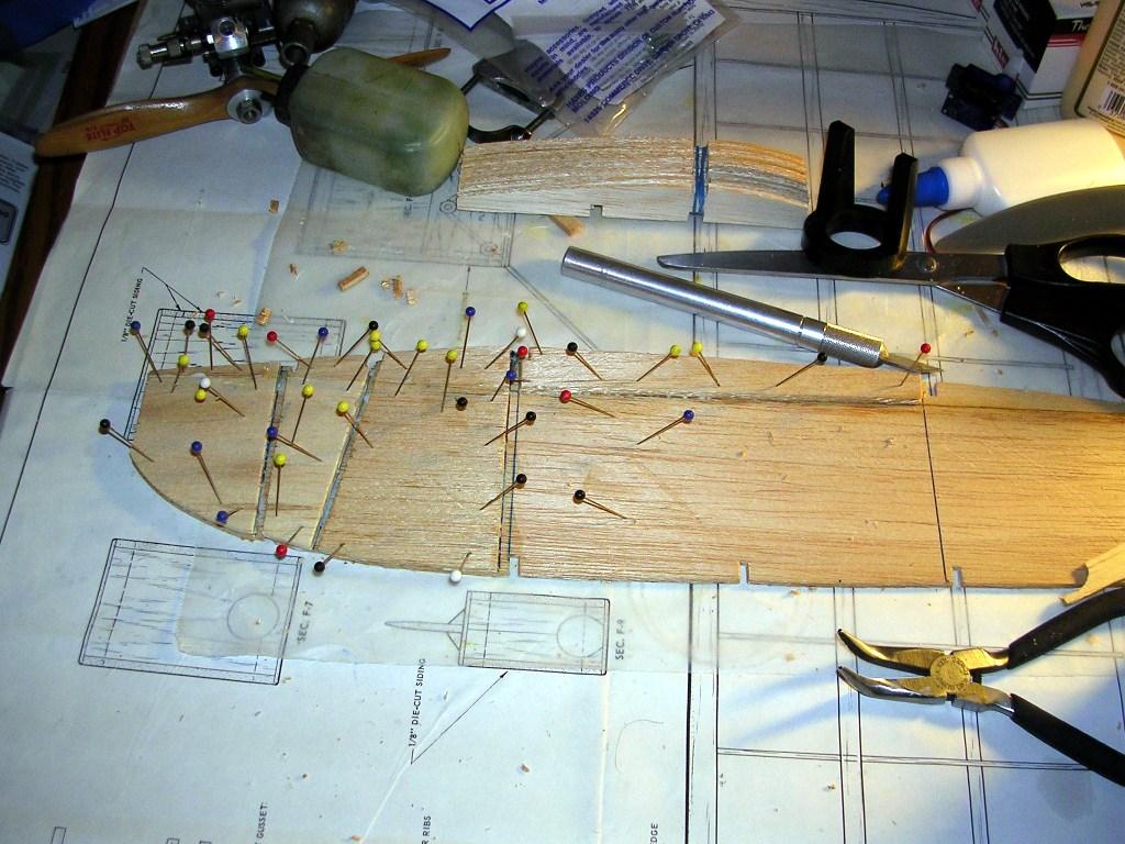
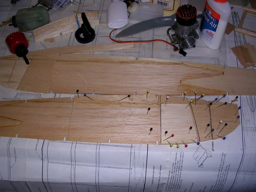
Next, I started to assemble the fuselage. The back half was easy.
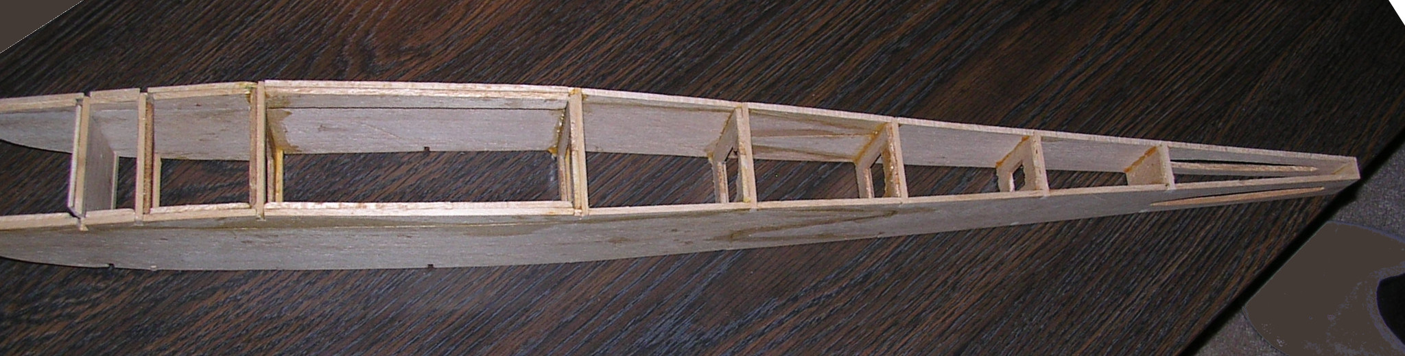
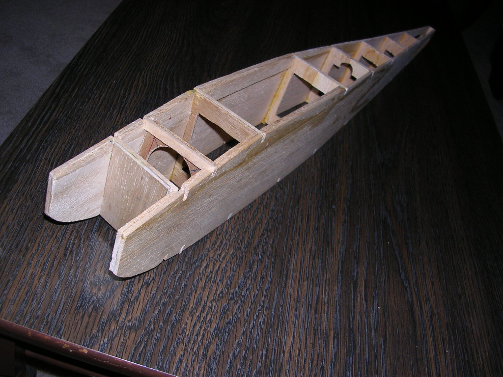
The hardest was the front. the fuselage with front front doublers made the wood 1/4" thick which is harder to align.
After the glue cured on the two forward buikheads, the check cowls wound up being too tight of a fit for the Enya .09-III engine's mounting lugs. Rather than attempt to extract the engine firewall, which would damage the fuselage, I needed to find another engine that was powerful enough to fly this 46" (1,168 mm) wingspan. The Thunder Tiger GP-07 fits like it was made for it, so this will be my powerplant.
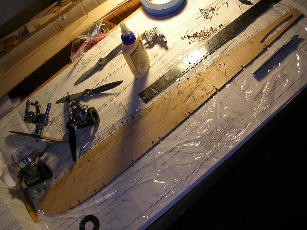
The fuselage edges required considerably sanding to true up the outine. By the mid 1960's, die cutting became more accurate. Today people are spoiled and rightly so for the accuracy that laser cutting has brought. The wood also wasn't sanded, with swirl marks caused by the rotary saws used to cut the balsa sheet. This Berkeley kit was rather rough by today's standards.
First, I reconnoitered the situation. I already had a good plan that I bought from Sig in the mid 1990's, when they were clearing out the remaining Berkeley plans they had in stock. It came with the original Berkeley plan envelope. As Kit P16-5 it sold for $1.00 US when Berkeley was still in business in the early 1960's. Of course I paid more for it from Sig, but it was still only a couple bucks.
First impressions of the kit .... it had a lot of die crunched pieces and plywood was the inferior quality Luan, not birch ply of later kits. Accuracy of die cutting left a little to be desired on larger pieces such as the fuselage halves.
First, I started off by cutting out the wing and stabilizer ribs, fuselage sides and formers, then start assembly.
Fit and finish of the fuselage sides were rough. I trimmed as best as possible, but still fell short, ended up splicing a little back to make a solid fuselage side from two pieces. Then pieced together the buikheads. Also removed balsa from the center of the bulkheads to reduce weight. To make room for the fuel tank, I cut out the center of the landing gear mounting bulkhead with a hole saw. To prevent from splitting the Luan, I rotated the bit manually by hand until I penetrated the first ply on the front side, then the back. Then chucked the bit in a hand held electric drill and finished the hole. This resulted in a clean hole in the Luan.
Next, I started to assemble the fuselage. The back half was easy.
The hardest was the front. the fuselage with front front doublers made the wood 1/4" thick which is harder to align.
After the glue cured on the two forward buikheads, the check cowls wound up being too tight of a fit for the Enya .09-III engine's mounting lugs. Rather than attempt to extract the engine firewall, which would damage the fuselage, I needed to find another engine that was powerful enough to fly this 46" (1,168 mm) wingspan. The Thunder Tiger GP-07 fits like it was made for it, so this will be my powerplant.
The fuselage edges required considerably sanding to true up the outine. By the mid 1960's, die cutting became more accurate. Today people are spoiled and rightly so for the accuracy that laser cutting has brought. The wood also wasn't sanded, with swirl marks caused by the rotary saws used to cut the balsa sheet. This Berkeley kit was rather rough by today's standards.
 02-17-2014, 12:36 AM
#2
Thread Starter
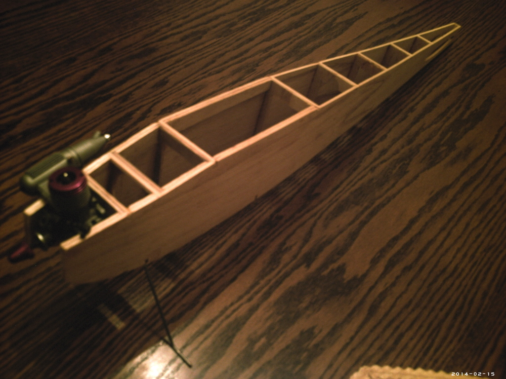
Two attachments for some reason do not show up on my post. They are Attachment 1969333 and Attachment 1969334. Here they are:
The fuselage also has a slightly warped rear, wood had a natural bow in it. I will remove this when I plank the fuselage top and bottom.
A comment regarding choice of engines. The plans show a 1950's vintage Fox .09 Rocket side port engine on it. From various inputs, power from this vintage engine was .049 like. The engine was easy starting, but not all that powerful. Since I live in a windy part of the US, it didn't make sense to put in such a weak engine. The A.C. Gilbert (yes, the train folks) .11 Thunderhead I purchased from Tower Hobbies about 12 years ago has more power, akin to a mild .09 engine. However this model has a 46" wingspan and with the local windy conditions, felt a more powerful Enya .09 III TV would be the right ticket.
However, I wasn't careful to watch the fitment of Bulkheads F-1 for the engine and F-2 for the landing gear. These are close coupled. The combination of F-1 being about 1/64" narrower and F-2 being about the same wider resulted in doubler cheek cowl nose pinch of 1/4" (6 mm) less.
Titebond Aliphatic water based resin glue is great stuff. Unfortunately, once glued it stays glued. This reduced my choices of engines to either the narrower Cox .074 Queen Bee, or Thunder Tiger GP-07 Schneurle.
The Cox being a really long engine sticks out an additional 1.5" (48mm) beyond the cowling. Plus, it doesn't have a muffler pressure tap. This made the GP-07 a better choice.
Last edited by GallopingGhostler; 02-17-2014 at 01:52 AM. Reason: Added comments regarding engine choice
02-23-2014, 12:22 AM
#3
Thread Starter
Left wing panel and elevator are coming right along. Two ribs were added and the center 4 ribs trimmed by 1/16" on both sides for 1/16" sheet planking. This will make the elevator covering easier to repair. The plans show no planking.
11-26-2015, 10:49 AM
#4
Join Date: Apr 2005
Location: peterborough,
ON, CANADA
Posts: 544
Likes: 0
Received 1 Like
on
1 Post
Maybe we can bring this old thread back to life.
I think George H. is around here somewhere.
I wonder how his Impulse flew?
I have an old "Impulse'' by Bill Johnke here.The plane looks to be in quite good condition except for a little hangar rash to the silkspan covering. Patched the covering last night with more silkspan & dope.
It has a Babcock compound esc. with a Relayer (super regen) rcvr.
Nicely built but appears to be a scratch built version as it has some ''Easybuilt'' Micro balsa sheeting in it.
Since I have the original M.A.N. Feb 54 construction article, I see that mine is rudder only as it does not have a kick up elevator as shown on Bill Johnke's plans.I do not have the Berkeley plan for comparison.
I plan to electrify it with a 400 XT outrunner and modern servos then add an elevator before flying it.
Bob
Last edited by boberos; 11-26-2015 at 10:54 AM.
