


AMR Trainer 26 - (my) official build thread
 12-01-2014, 08:27 AM
#176
Banned
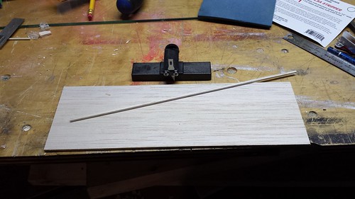
The manual does not specify a dowel length so I eyeballed it from the pictures.
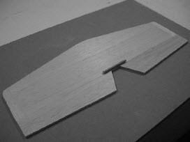
There are servo bays at the back of the fuse and I plan to use two elevator servos there.
The dowel is a backup in case the plane is too tail heavy and requires a single centrally located elevator servo. If that's the case then I'll consider your suggestion, Zor. If all goes to plan I will separate the dowel halves.
Thanks, fellas.
The elevators should remain perfectly flat when air ( aerodynamic ) forces are exerted on them.
A sheet will be hard to bend along the grain but can easily bend crosswise ( 90 degrees to the grain ).
So ... the elevators need wood grain fore and aft.
From the pictures I ( we ) do not know if the elevators are made of ply _ _ _ if they are not then they could bend and even induce flutter _ _ _ thus the suggestion to have some stiffness LE to TE provided by a metal U shaped wire.
There was no evidence up to now that you intended to use two servos ( one on each elevator ).
If you proceed with two servos, it is suggested that you make sure they match; that they rotate very close to the same degrees of rotation from the same signal sent to them. It would be detrimental if the two elevators were not rotating the same amount and thus provide a short moment arm aileron effect.
Even with two servos the elevators' bending is a different situation that still exist. If those elevators are not ply and do not have lengthwise chord oriented wood grain, they could have some bending that is not desirable. From what is seen in the pictures the glued dowell provides torque only in its immediate vicinity on the wood grain _ _ _ thus the advantage of having some wood grain going from leading edge to trailing edge of the elevators.
Notice that I have no comments about your nice work but I question the design in this area.
If the flying style is always gentle there might be no problems but that may not be true if agressive flying is involved.
Of course _ _ _ do what you are comfortable with but any possible consequences are still there..
Enjoy your nice work,
Zor
Last edited by Zor; 12-01-2014 at 08:33 AM.
 12-01-2014, 04:19 PM
#177
Senior Member
Thread Starter

Thanks for the input. I have no intention of flinging this flat-bottomed trainer airplane around the sky - I have sportier planes for that.
12-02-2014, 06:14 PM
#178
Senior Member
Thread Starter
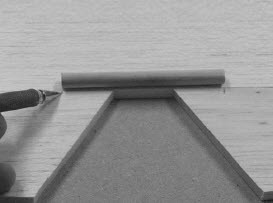
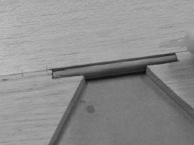
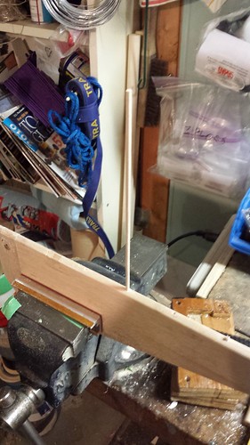
Gentle people, your advice has not fallen on deaf ears. With the skill of a surgeon ( ) I have cut out the short dowel and replaced it with a much longer version.
) I have cut out the short dowel and replaced it with a much longer version.
12-03-2014, 07:35 AM
#179
Senior Member
Thread Starter
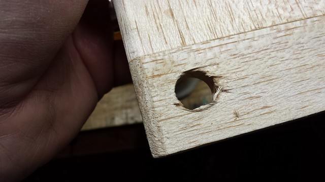
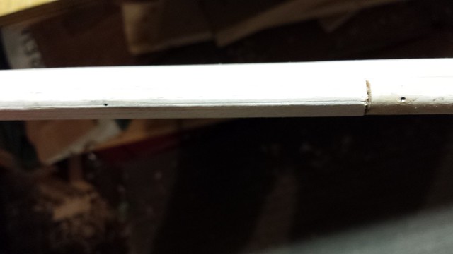
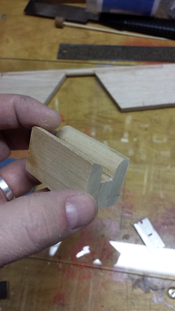
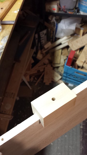
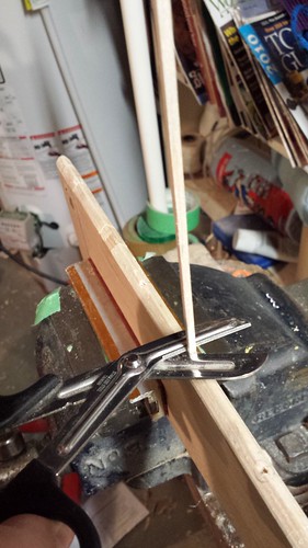
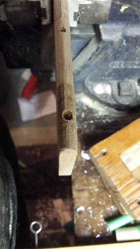
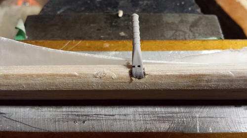
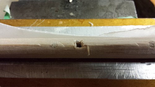
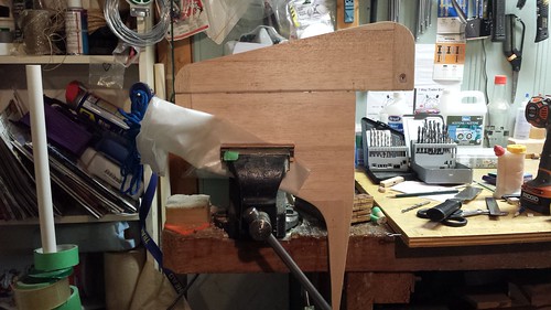
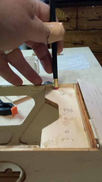
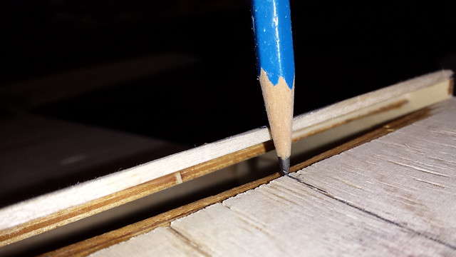
The tail wheel will be steered by a through-bolted control horn low on the rudder near the leading edge. Because the rudder (like all of the empennage surfaces) is solid balsa I inserted a dowel, centre-drilled to 9/64" for the 6-32 bolt.
Here's the hole for the dowel. Yes, it could have been cleaner - that's something to work on.
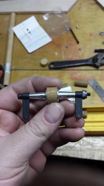
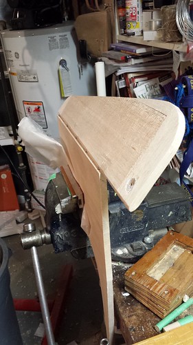
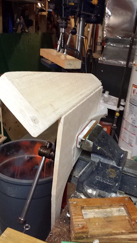
Control horn test fit on the dowel piece.
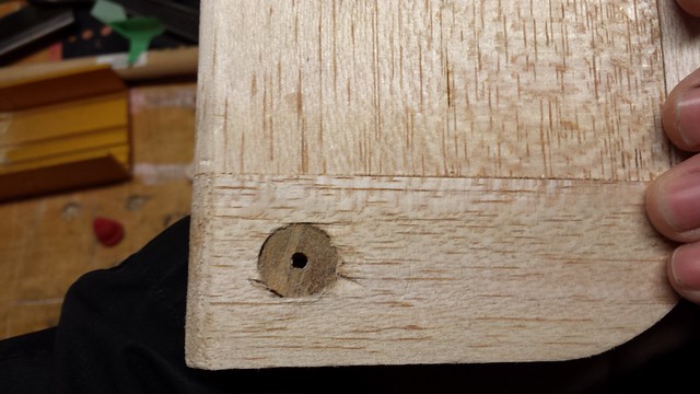
Dowel glued in place.
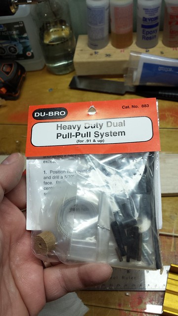
I'm planning on a pull-pull rudder. I'll take the same dowel-in-rudder approach; there was enough left over so I cut it to length and stuck it in the bag with the other parts.
Here's the hole for the dowel. Yes, it could have been cleaner - that's something to work on.
Control horn test fit on the dowel piece.
Dowel glued in place.
I'm planning on a pull-pull rudder. I'll take the same dowel-in-rudder approach; there was enough left over so I cut it to length and stuck it in the bag with the other parts.
12-03-2014, 07:48 AM
#180
Senior Member
Thread Starter
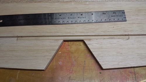
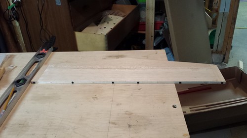
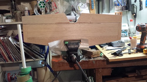
I transferred the hinge point locations from the horizontal stabilizer to the elevators in the same way I did with the vertical stabilizer and rudder.
Blind hole spotters in the stab.
Align stab with elevators.
Slide together to make marks.
Blind hole spotters in the stab.
Align stab with elevators.
Slide together to make marks.
12-03-2014, 07:51 AM
#181
Senior Member
Thread Starter
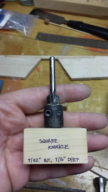
During this morning's shop session I made a jig for the knuckle and the thicker section of the hinge points.
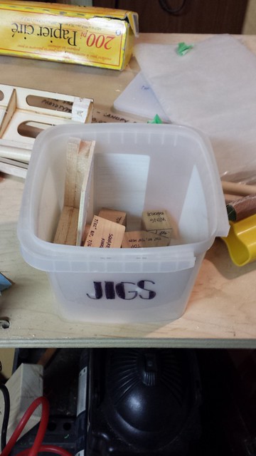
That's five jigs for this build - I figured I'd better find a place for them.
That's five jigs for this build - I figured I'd better find a place for them.
12-03-2014, 05:53 PM
#182
Senior Member
Thread Starter
On the advice of a trusted fellow modeler I have adjusted the hinge spacing to have hinges closer to the edges of the controls.
Elevator:
Rudder:
I started with the stabilizers, filling holes with glue and sections of bamboo skewer.
The skewers were easy to cut flush.
Elevator:
Rudder:
I started with the stabilizers, filling holes with glue and sections of bamboo skewer.
The skewers were easy to cut flush.
12-03-2014, 06:03 PM
#183
Senior Member
Thread Starter
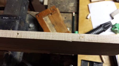
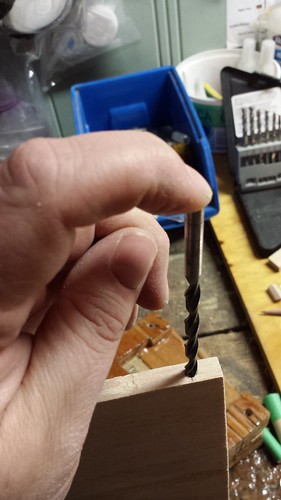
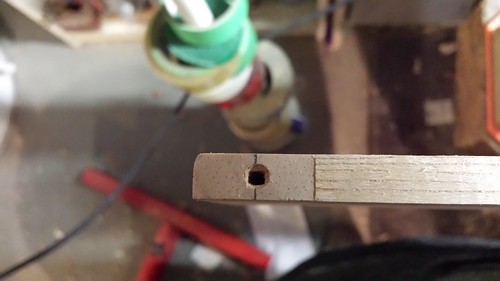
Bamboo was fine until I got to the leading edges of the control surfaces. I didn't think they'd be quite as easy to cut so I decided to try out the balsa stripper I picked up the other day. I made a 1/8" x 1/8" plug.
A little sanding to knock down the corners and it slid in just fine.
I just trimmed them off with scissors.
When the glue cured they were easy to plane or sand as needed.
When all the new holes were drilled, I tried out my knuckle jig. Ruh roh... off centre.
A little sanding to knock down the corners and it slid in just fine.
I just trimmed them off with scissors.
When the glue cured they were easy to plane or sand as needed.
When all the new holes were drilled, I tried out my knuckle jig. Ruh roh... off centre.
12-03-2014, 06:11 PM
#184
Senior Member
Thread Starter
No worries - for balsa most of the knuckle could be formed just by pushing a hinge in.
The last little bit of the knuckles were made by turning the 7/32" bit counter-clockwise by hand.
The last little bit of the knuckles were made by turning the 7/32" bit counter-clockwise by hand.
12-03-2014, 06:16 PM
#185
Senior Member
Thread Starter
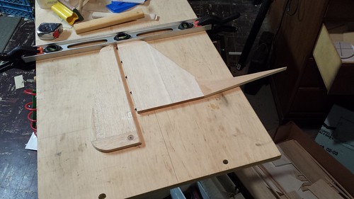
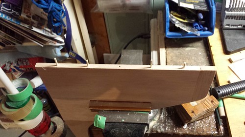
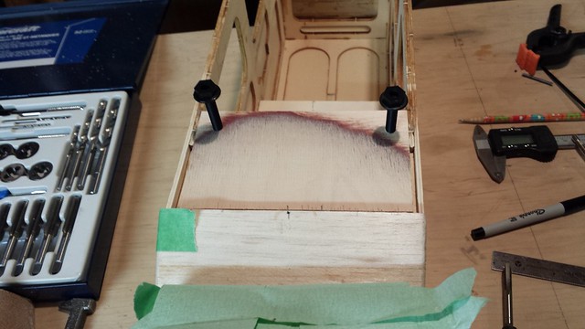
The elevator dowel, being hardwood, had to be done with the drill.
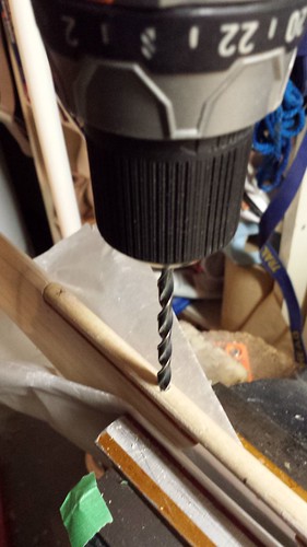
Here is the elevator on the horizontal stabilizer.
And here is the deflection, one way...
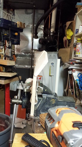
...and the other.
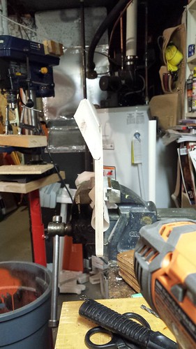
Here is the elevator on the horizontal stabilizer.
And here is the deflection, one way...
...and the other.
 12-05-2014, 08:59 AM
#187
Senior Member
Thread Starter
Rapidly approaching is step 83 in the manual, which contains the following
"It is also a good time to verify the stab incidence by setting the wing a +1 (factory set) and the stab at 0-degress. Sand/shim as necessary for optimum tolerance."
I have a basic understanding of incidence but no idea how to check it or change it if required. Advice would be appreciated.
"It is also a good time to verify the stab incidence by setting the wing a +1 (factory set) and the stab at 0-degress. Sand/shim as necessary for optimum tolerance."
I have a basic understanding of incidence but no idea how to check it or change it if required. Advice would be appreciated.
12-05-2014, 01:32 PM
#188
Banned
Rapidly approaching is step 83 in the manual, which contains the following
"It is also a good time to verify the stab incidence by setting the wing a +1 (factory set) and the stab at 0-degress. Sand/shim as necessary for optimum tolerance."
I have a basic understanding of incidence but no idea how to check it or change it if required. Advice would be appreciated.
"It is also a good time to verify the stab incidence by setting the wing a +1 (factory set) and the stab at 0-degress. Sand/shim as necessary for optimum tolerance."
I have a basic understanding of incidence but no idea how to check it or change it if required. Advice would be appreciated.
Some description may help you . . . .
My first comment is regarding the drilling of the elongated dowel joining the elevators. It seem to me that this drilling pretty well nearly defeated the change to a longer length. I did not see anything to prevent or reduce any elevator bending front to back.
How to setup the incidences.
The incidences are angles referred to a reference ususally the longitudinal axis of the fuselage.
Many folks have bought an incidence measuring commercial device. Some of those devices provide errors due to the mehod they relate to the flying surfaces. I will not elaborate on this right now but I can provide answers if anyone needs.
I do my setups with measurements using a scale reading accuracy of 1/64 of an inch.
We have to verify the specified data if it is using the chords of airfoils as should be. Some data are using the bottom flat surface of a Clark Y airfoil ( for example ).
I sit the fuselage on the flat work area and adjust the reference line to be parrallel to the work surface.
Then I measure the diatances from the work surface to the foremost points of the wings leading edges. Those points where a vertical ruler ( 90 degrees with the work surface ) touches the leading edge ( the chord version ). I do that near the wing roots, half way out and near the wing tips. Write down the measurements. I do the same at the trailing edges ( at half the TE thickness ).
Same method used for the stabilizer. Then simple mathematics calculate the angles.
The at least three measurements for the main wings gives me also the amount of washout if any has been used building the wings.
Hope this help. It cost nothing and it is accurate.
Concerning any adjustments, it is done at the stabilizer which is why I never glue the tail assembly; I bolt it and use shims if needed to obtan the proper decalage angle.
Zor
Last edited by Zor; 12-05-2014 at 01:35 PM.
12-06-2014, 01:36 PM
#189
Senior Member
Thread Starter
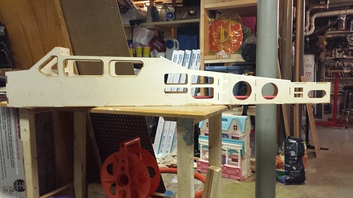
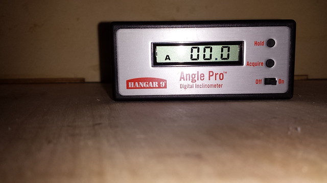
I picked up a Hangar 9 Angle Pro and the optional 36" extension bar at my LHS yesterday.
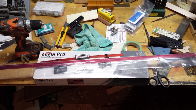
There are no plans with this kit and the manual makes no reference to a thrust line. I checked the firewall and it was square to the bottom of the plane, which is flat, so I figure I'd use that. So I put the Angle Pro on the workbench and zeroed it.
I set the plane on the bench and checked the wing saddle - +1.1� degrees (I confirmed this despite the minus sign), which is very close to the expected 1.0�.
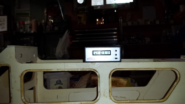
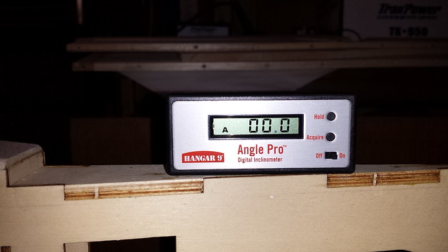
The horizontal stabilizer mounting surface was 0.0� - right on the money.
There are no plans with this kit and the manual makes no reference to a thrust line. I checked the firewall and it was square to the bottom of the plane, which is flat, so I figure I'd use that. So I put the Angle Pro on the workbench and zeroed it.
I set the plane on the bench and checked the wing saddle - +1.1� degrees (I confirmed this despite the minus sign), which is very close to the expected 1.0�.
The horizontal stabilizer mounting surface was 0.0� - right on the money.
12-06-2014, 01:45 PM
#190
Senior Member
Thread Starter
Once I got the horizontal stabilizer centred I checked it: - 0.1�. Looking good.
Things started to go wonky at the wing, though. The first time I checked it was +1.6� on the starboard wing and +3.6� on the port wing. This made no sense to me. I tried again and I was able to get +1.0� starboard and +1.6� port, but only after blocking the rear of the wing up a LOT.
Because of the way the wing is built I'm quite sure that it's flat on the bottom, so I'm not sure what's causing these inconsistencies. Shape of the leading and trailing edge, perhaps? It's a puzzler.
12-06-2014, 03:26 PM
#191
Banned
grosbeak,
Looks like you have to do some work on the wing saddles on both sides.
Ya _ _ _ that is evident.
Before doing that work however I would check the wing panels for washin or washout ( twisted wings ).
Some washout is good but it has to be equal ( both side the same ).
Ya _ _ _ it may be said that lateral trimming can take care of unequal wing twist.
Only you can decide what you wish to do.
Ideally both wings should present the same average angle of attack in straight and level flight.
It appears from your readings with that meter that the decalage is plus 1.1 degrees ( main wings to stab ).
If the elevators are neutral the model will need a fair speed with that small a decalage angle. The speed will also depend on the airfoil in use ( obviously ).
Zor
12-08-2014, 08:53 AM
#192
Senior Member
Thread Starter
It's been suggested to me that for a CNC-cut trainer build I have been overthinking this and AMR agrees so I will set the incidence meter aside for a more advanced build and will proceed with this one!
12-08-2014, 09:50 AM
#193
Senior Member
I agree. You are doing a good job. I am enjoying following your build. Whether the angle is 1.1� or 1.0� ----- Nobody will notice from 50 feet!
12-08-2014, 05:55 PM
#194
Senior Member
Thread Starter
12-10-2014, 06:24 AM
#195
Senior Member
Thread Starter
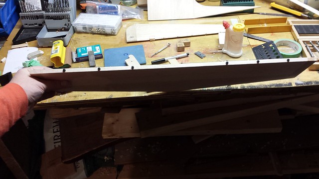
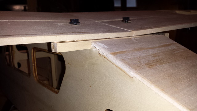
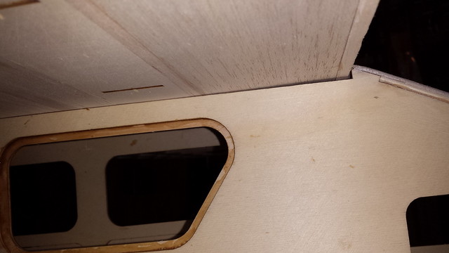
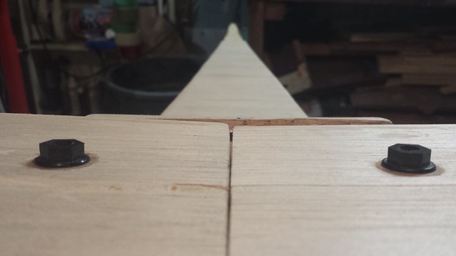
I noticed sizable gaps between fuselage and wing at the rear.
Remember when I discovered that the wing bolt anchor plate was not flush?
And remember when I installed this plate to (a) extend the bolting location and (b) make it flush?
Remember when I discovered that the wing bolt anchor plate was not flush?
And remember when I installed this plate to (a) extend the bolting location and (b) make it flush?
12-10-2014, 06:34 AM
#196
Senior Member
Thread Starter
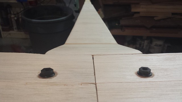
Well, that was a mistake because it doesn't account for the dihedral in the wing (the bulkhead behind the plate does).
Time for the rotary tool. Lots of sawdust and a couple of sanding drums later - done. Functional if not pretty.
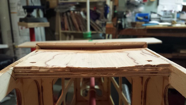
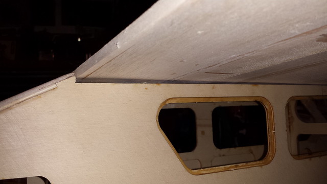
Big improvement with the gap (wing not bolted down in these photos).
Time for the rotary tool. Lots of sawdust and a couple of sanding drums later - done. Functional if not pretty.
Big improvement with the gap (wing not bolted down in these photos).
12-10-2014, 10:38 AM
#197

My Feedback: (13)
Hay Buddy,
Nice recovery. I too am building an AMR kit and it is also the first kit I've ever built without any plans. What happened to you could have happened to anyone building the model. Your doing a direct conscious build of a model without any plans and the issues your having, to me, is directly the cause of not having a set of plans to refer to, during your build. I found several anomalies with my build too and its frustrating at best. It is also a learning curve for you, or anyone building a model without a reference plans to refer to.
I have contacted AMR about not having any plans and informed them that at the price of the kit I purchased, shipped to Hawaii, I would have been more then happy to pay a few extra bucks for a nice set of plans ($580.00). If you ever have a less then perfect landing with your model, and need major repairs, with no plans, your locked into buying from AMR to get any spar parts. Just ask them what a new wing kit will cost...it will be 70%, of the cost of the full kit. I do enjoy building, but it would have been a more enjoyable build with a set of plans, plus I would have the plans to cut more wood to do any major or minor repairs.
AMR kits are well cut and for the most part, and I am not able to fault the CNC computer cut work on the kit. But with out plans, the building instructions need to be very accurate and up to date. My instructions were not up to date and the kit had several anomalies that the build instructions didn't cover, that created a bit of frustration for me.
Good work and I am following your build.
Soft Landings Always,
Bobby of Maui
12-10-2014, 11:15 AM
#198
Senior Member
Thread Starter
Hay Buddy,
Nice recovery. I too am building an AMR kit and it is also the first kit I've ever built without any plans. What happened to you could have happened to anyone building the model. Your doing a direct conscious build of a model without any plans and the issues your having, to me, is directly the cause of not having a set of plans to refer to, during your build. I found several anomalies with my build too and its frustrating at best. It is also a learning curve for you, or anyone building a model without a reference plans to refer to.
I have contacted AMR about not having any plans and informed them that at the price of the kit I purchased, shipped to Hawaii, I would have been more then happy to pay a few extra bucks for a nice set of plans ($580.00). If you ever have a less then perfect landing with your model, and need major repairs, with no plans, your locked into buying from AMR to get any spar parts. Just ask them what a new wing kit will cost...it will be 70%, of the cost of the full kit. I do enjoy building, but it would have been a more enjoyable build with a set of plans, plus I would have the plans to cut more wood to do any major or minor repairs.
AMR kits are well cut and for the most part, and I am not able to fault the CNC computer cut work on the kit. But with out plans, the building instructions need to be very accurate and up to date. My instructions were not up to date and the kit had several anomalies that the build instructions didn't cover, that created a bit of frustration for me.
Good work and I am following your build.
Soft Landings Always,
Bobby of Maui
Nice recovery. I too am building an AMR kit and it is also the first kit I've ever built without any plans. What happened to you could have happened to anyone building the model. Your doing a direct conscious build of a model without any plans and the issues your having, to me, is directly the cause of not having a set of plans to refer to, during your build. I found several anomalies with my build too and its frustrating at best. It is also a learning curve for you, or anyone building a model without a reference plans to refer to.
I have contacted AMR about not having any plans and informed them that at the price of the kit I purchased, shipped to Hawaii, I would have been more then happy to pay a few extra bucks for a nice set of plans ($580.00). If you ever have a less then perfect landing with your model, and need major repairs, with no plans, your locked into buying from AMR to get any spar parts. Just ask them what a new wing kit will cost...it will be 70%, of the cost of the full kit. I do enjoy building, but it would have been a more enjoyable build with a set of plans, plus I would have the plans to cut more wood to do any major or minor repairs.
AMR kits are well cut and for the most part, and I am not able to fault the CNC computer cut work on the kit. But with out plans, the building instructions need to be very accurate and up to date. My instructions were not up to date and the kit had several anomalies that the build instructions didn't cover, that created a bit of frustration for me.
Good work and I am following your build.
Soft Landings Always,
Bobby of Maui
Because I've never built an RC plane from a kit before I'm not concerned with a lack of plans. I've done a lot of ARF repairs during my short time in the hobby and I find I can usually figure out what to do once I strip the covering off.
However, I do agree that the manual could use a lot of improvement, especially for what's supposed to be a beginner kit. There's plenty of missing information and a lot of guesswork involved, and it would benefit from a thorough proofreading.
On the upside, AMR has been responsive to my questions and I'm keeping this build current on five forums so there's plenty of help around.
12-16-2014, 03:34 PM
#199
Senior Member
Thread Starter
A few days away from the build but I'm back at it now.
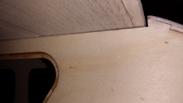
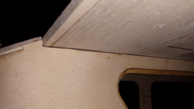
I noticed that the rear of the wing saddle doesn't line up properly with the wing.
I glued in a balsa doubler below the surface skin.
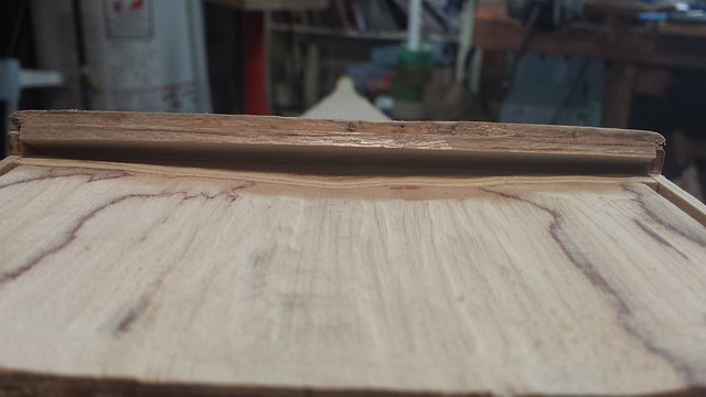
A bit of sanding - not perfect, but it looks better.
I noticed that the rear of the wing saddle doesn't line up properly with the wing.
I glued in a balsa doubler below the surface skin.
A bit of sanding - not perfect, but it looks better.
12-16-2014, 03:41 PM
#200
Senior Member
Thread Starter
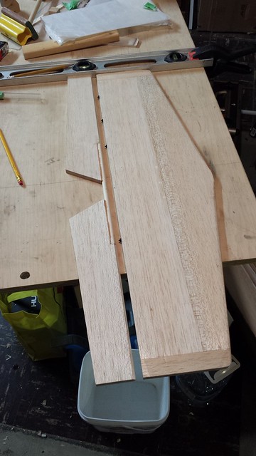
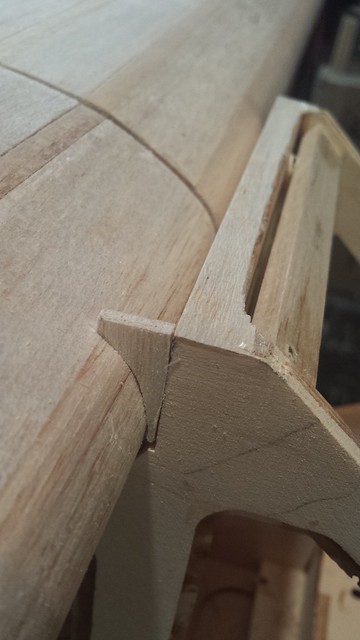
In other news, I removed the original top strip from above the front window frame.
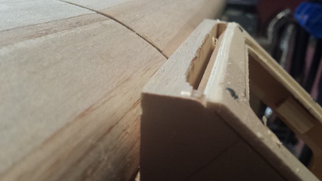
I wanted a longer piece to fair in the unsightly gap between the front of the wing saddle and the centre leading edge of the wing.
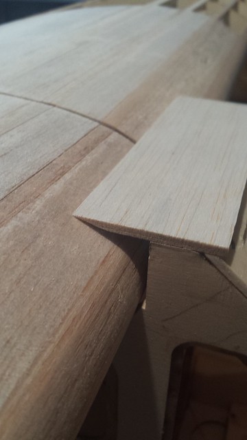
To make the side pieces I used some soft wire to copy the wing profile.
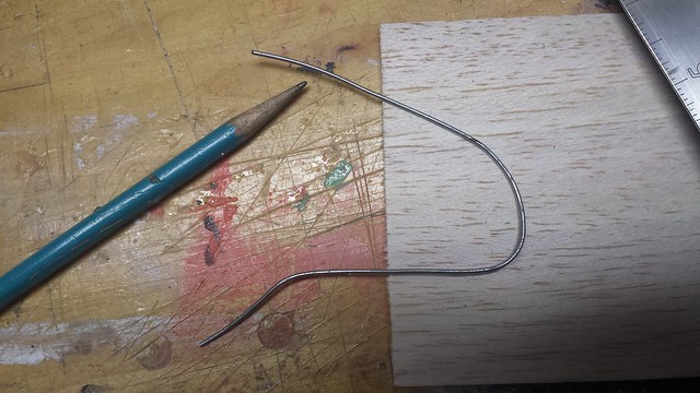
After tracing the profile onto some scrap 1/8" balsa and cutting it out, a little sanding got it to fit.
I wanted a longer piece to fair in the unsightly gap between the front of the wing saddle and the centre leading edge of the wing.
To make the side pieces I used some soft wire to copy the wing profile.
After tracing the profile onto some scrap 1/8" balsa and cutting it out, a little sanding got it to fit.