


AMR Trainer 26 - (my) official build thread
 11-28-2014, 07:22 AM
#151
Senior Member
Thread Starter

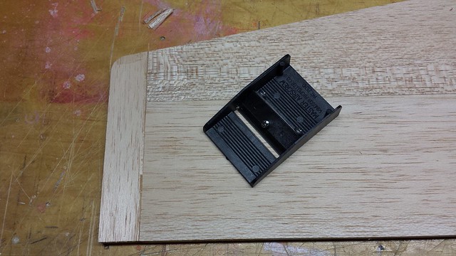
I have a piece of 1/8" balsa that's just right for the top.

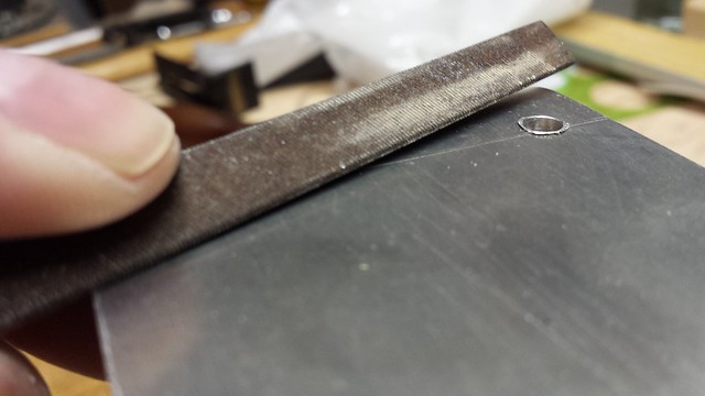
A test bevel with the razor plane worked very well.
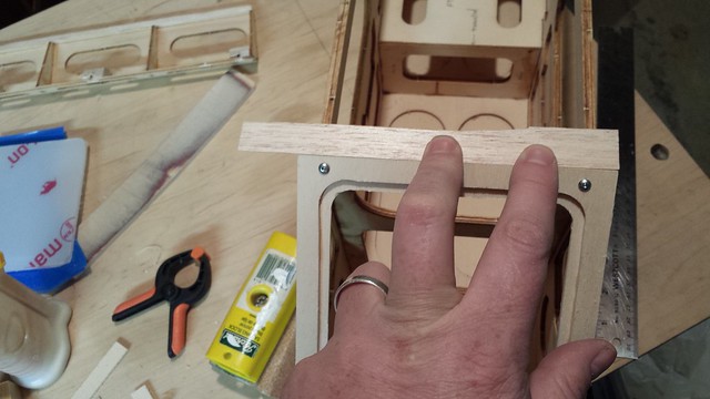
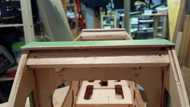
The finished piece beveled, glued and taped.
A test bevel with the razor plane worked very well.
The finished piece beveled, glued and taped.
 11-29-2014, 04:35 AM
#152
Senior Member
Thread Starter
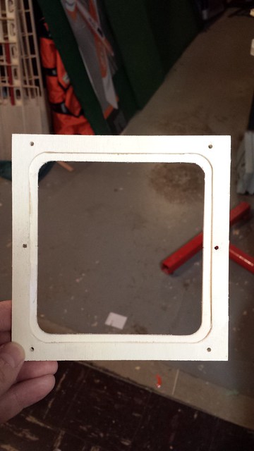
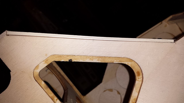
To address the gap on the side of the windshield frame I centred a new pair of holes between top and bottom.
Matching balsa blocks.
After all the usual marking, drilling, threading, CA, etc, I reinstalled the frame with the 6 screws and the gap was gone.
Matching balsa blocks.
After all the usual marking, drilling, threading, CA, etc, I reinstalled the frame with the 6 screws and the gap was gone.
11-29-2014, 04:43 AM
#153
Senior Member
Thread Starter
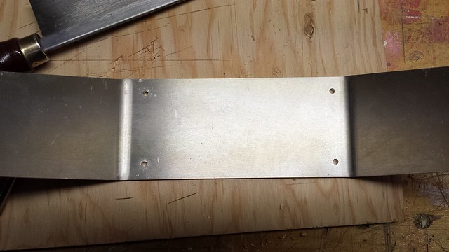
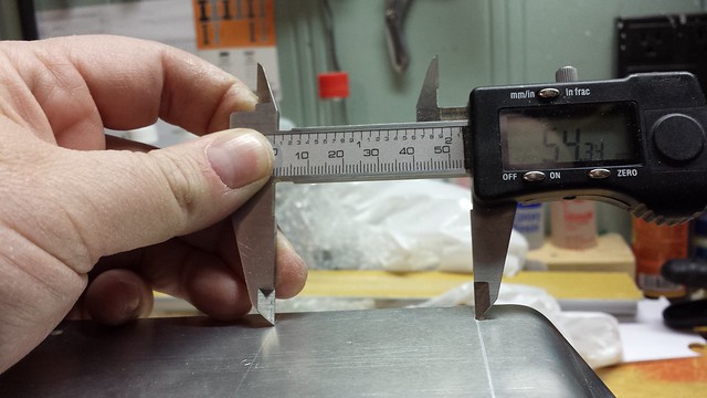
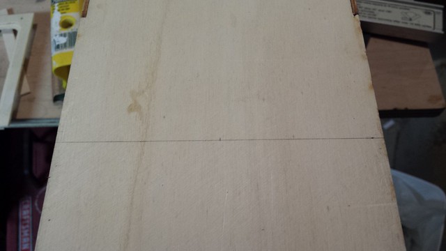
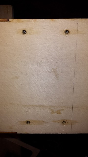
On to the main gear. A problem was immediately apparent - the holes are not equidistant from the sides.
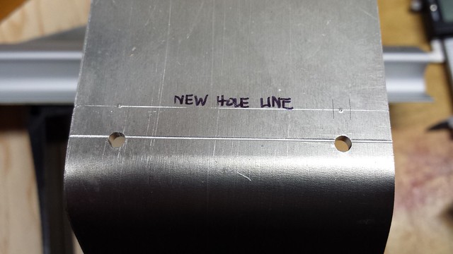
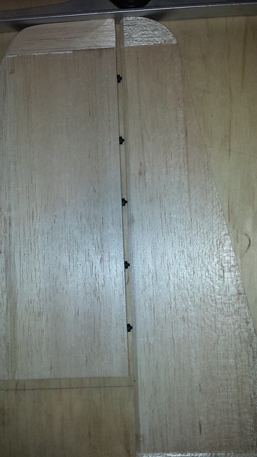
I started by marking a centre line.
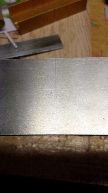
Gear holes are 60.06mm from one side...
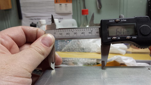
...and 54.34mm from the other.
I started by marking a centre line.
Gear holes are 60.06mm from one side...
...and 54.34mm from the other.
11-29-2014, 04:48 AM
#154
Senior Member
Thread Starter
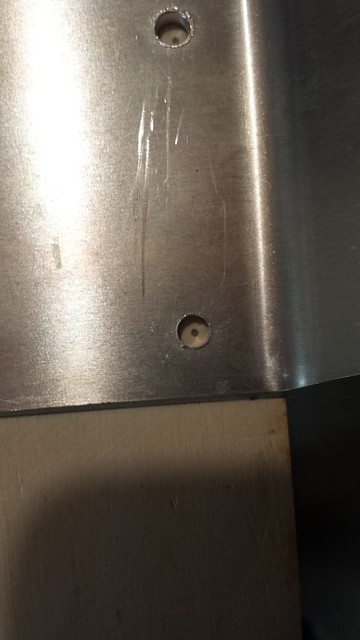
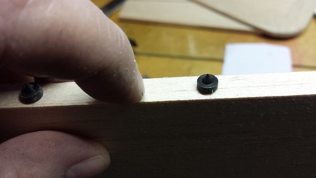
I marked the location of the new holes...
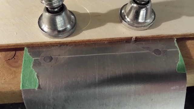
...and filled the old holes with JB Weld.
Drilling the new holes.
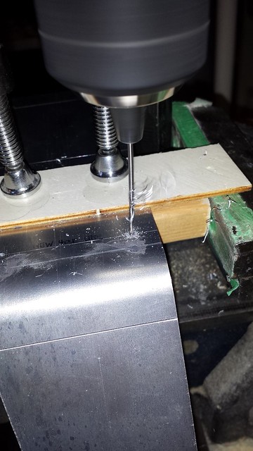
Removing the drilling burrs.
...and filled the old holes with JB Weld.
Drilling the new holes.
Removing the drilling burrs.
 11-29-2014, 11:51 AM
#157
Banned
11-29-2014, 02:17 PM
#158
Senior Member
Thread Starter
Thanks, fellas. I used to take my DSLR into the shop for project photos - now I do all that with the camera on my Samsung Galaxy S4.
11-29-2014, 04:11 PM
#159
Senior Member
Thread Starter
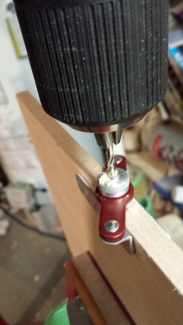
Step 77 specifies installation of the gear with 6-32 bolts and blind nuts. This would work if installation of tank try F10 back in step 10 hadn't covered up inside access to the front holes. No sweat; I have another tried and true method at hand: #10 wood screws.
Drilling the holes.
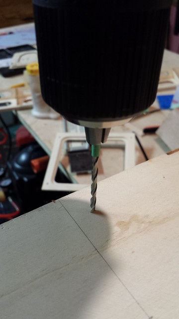
Drilled, threaded and drizzled with CA.
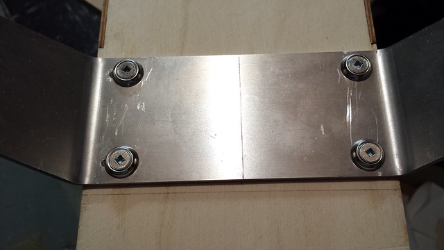
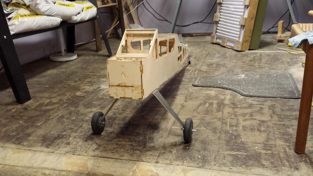
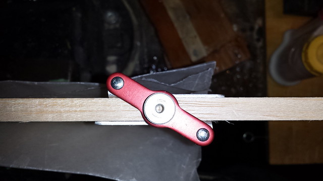
Step 78 directs the builder to use socket head cap screws as axles. I prefer the spring steel Du-Bro models so I drilled out the axles holes to 5/16" to accommodate them.
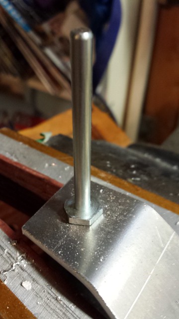
Landing gear mounted.
Drilling the holes.
Drilled, threaded and drizzled with CA.
Step 78 directs the builder to use socket head cap screws as axles. I prefer the spring steel Du-Bro models so I drilled out the axles holes to 5/16" to accommodate them.
Landing gear mounted.
11-29-2014, 04:36 PM
#160
Senior Member
Thread Starter
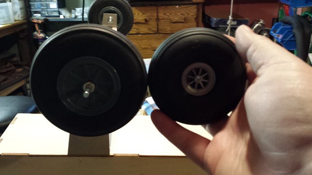
I had some 4" wheels in the shop so I'm using those instead of the supplied 3-1/2" wheels.
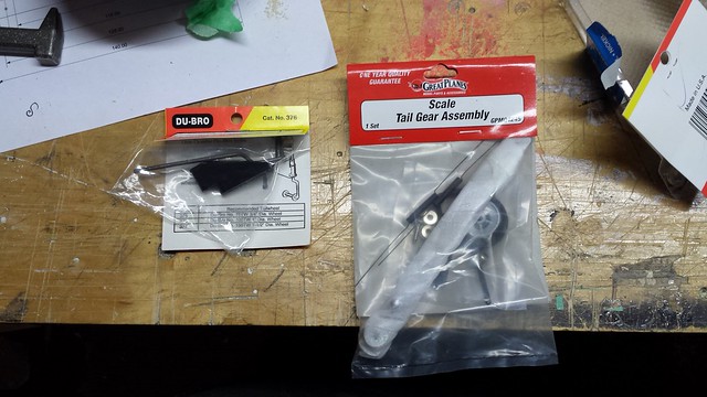
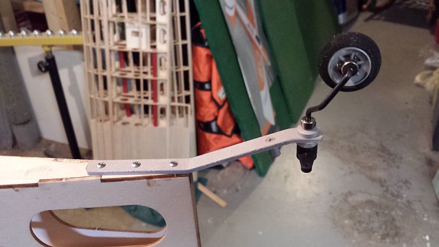
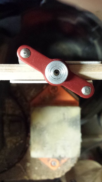
I also don't like the supplied tail wheel bracket so I'm going with a Great Planes model that I've used before.
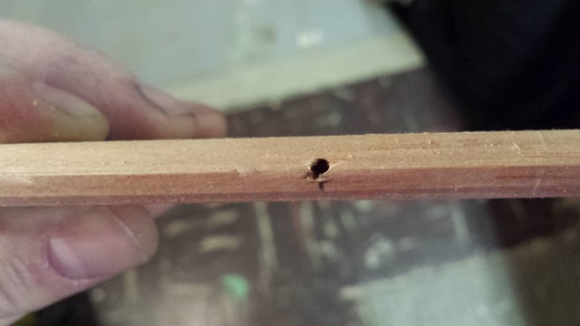
I figured that the tail wheel arm would benefit from a third hole - here the location is marked.
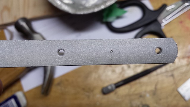
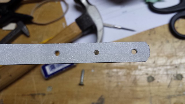
Hole drilled.
I also don't like the supplied tail wheel bracket so I'm going with a Great Planes model that I've used before.
I figured that the tail wheel arm would benefit from a third hole - here the location is marked.
Hole drilled.
11-29-2014, 04:41 PM
#161
Senior Member
Thread Starter
Marking the holes for the tail wheel bracket.
[url=https://flic.kr/p/qctv95]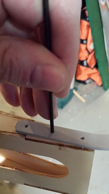 [/url
[/url
Drilling the marked holes.
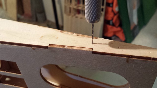
Holes drilled. Threading a CA followed.

Tail wheel installed.
 a
a
[url=https://flic.kr/p/qctv95]
[/urlDrilling the marked holes.
Holes drilled. Threading a CA followed.
Tail wheel installed.
a
 11-30-2014, 05:54 PM
#163
Senior Member
Thread Starter
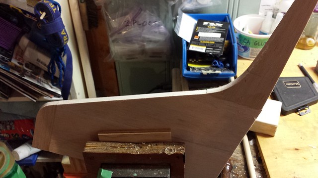
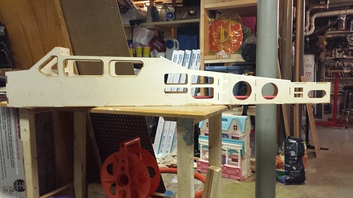
On to the empennage. Back in the first pages I cut all the pieces out from 3/8" balsa and glued the relevant parts together. When I got them out again the first thing I did was to go over the joined with a razor plane to knock off any glue and high spots.
The manual makes no reference to the stabilizer leading edges but I've not see square ones yet. I clamped the horizontal stabilizer in the vise - GENTLY - to work on it.
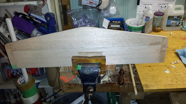
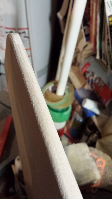
The very first pass with the razor plane.
Nicely rounded.
The manual makes no reference to the stabilizer leading edges but I've not see square ones yet. I clamped the horizontal stabilizer in the vise - GENTLY - to work on it.
The very first pass with the razor plane.
Nicely rounded.
 11-30-2014, 06:02 PM
#165
 11-30-2014, 06:07 PM
#166
Senior Member
Thread Starter
11-30-2014, 06:13 PM
#168
Senior Member
Thread Starter
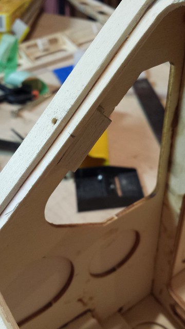
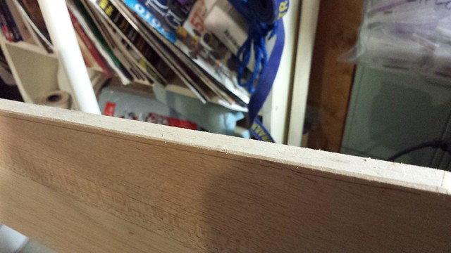
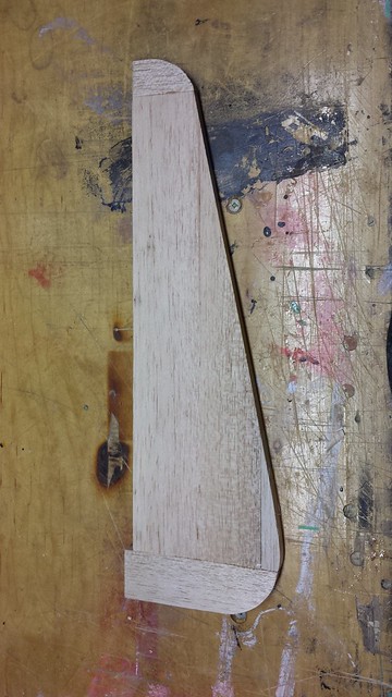
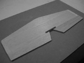
The rudder one of the rudder hinges is supposed to go in the rear of the fuselage. Not going to happen until I fill this gap.
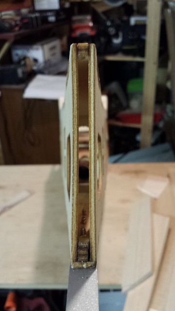
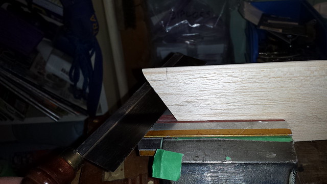
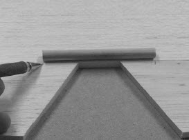
This was a piece of 3/8" balsa but I've planed it to thickness. The notch is for the part of the tail wheel bracket screw that sticks out. Why didn't I just remove the screw and re-install it afterwards? Damn good question!
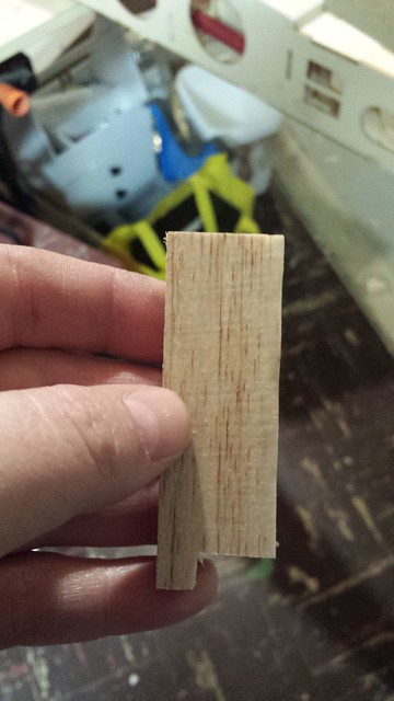
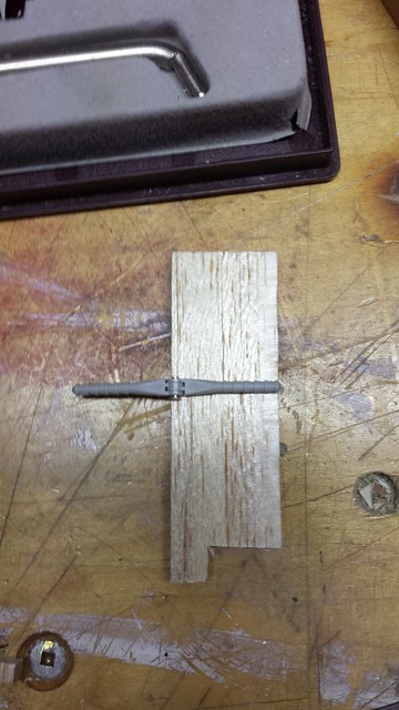
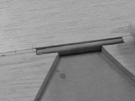
Just the right depth for a hinge point.
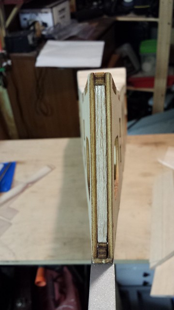
Glued in place.
This was a piece of 3/8" balsa but I've planed it to thickness. The notch is for the part of the tail wheel bracket screw that sticks out. Why didn't I just remove the screw and re-install it afterwards? Damn good question!
Just the right depth for a hinge point.
Glued in place.
11-30-2014, 06:17 PM
#169
Senior Member
Thread Starter
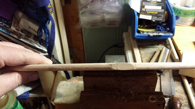
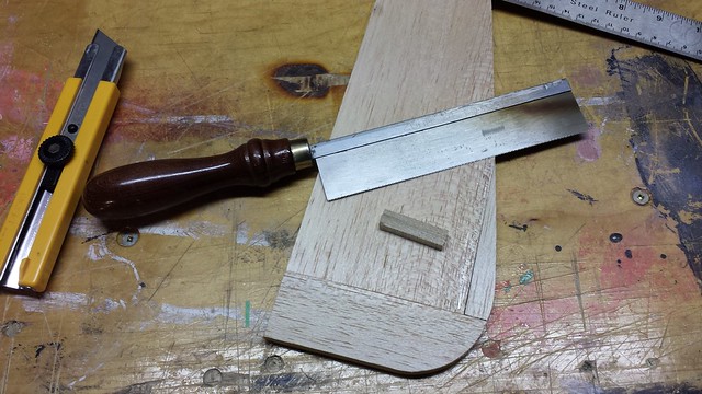
This is the dowel that joins the two elevators together.
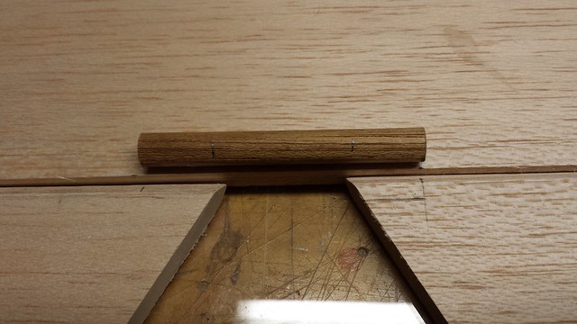
The elevators must be notched - this one's marked and ready for cutting.
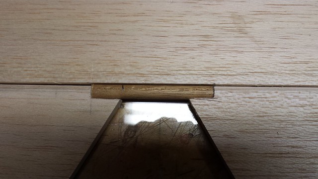
Test fit.
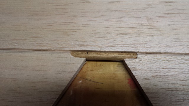
Glued in. The dowel is only glued to the elevators - I made sure of that - but the whole thing is pushed against the horizontal stabilizer to keep it straight.
The elevators must be notched - this one's marked and ready for cutting.
Test fit.
Glued in. The dowel is only glued to the elevators - I made sure of that - but the whole thing is pushed against the horizontal stabilizer to keep it straight.
11-30-2014, 06:26 PM
#170
Senior Member
Thread Starter
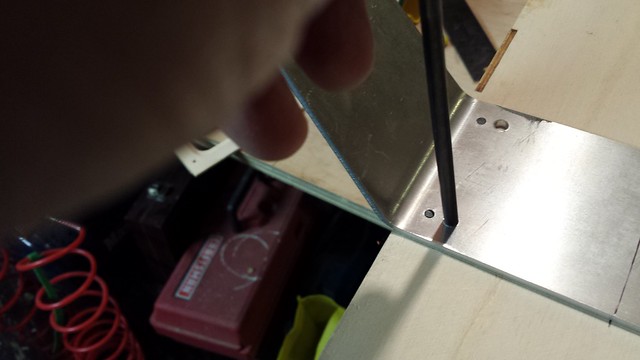
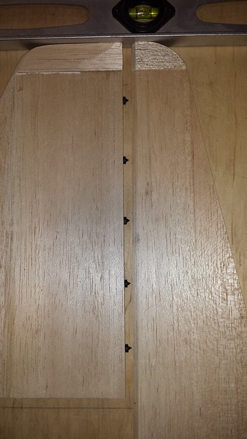
Time to make the hinge holes in the vertical stabilizer and rudder. I marked across the trailing edge of the stab where I wanted the hinges to go and made sure the line was visible through the Robart centring jig.
Drilling the hinge point holes.
When all of the holes were drilled I put these 1/8" blind hole spotters in place.
Drilling the hinge point holes.
When all of the holes were drilled I put these 1/8" blind hole spotters in place.
11-30-2014, 06:28 PM
#171
Senior Member
Thread Starter
The stab and rudder were lined up...
... and pushed together to mark the rudder.
I darkened the marks with a pencil to make them more visible through the jig.
Drilling the holes.
... and pushed together to mark the rudder.
I darkened the marks with a pencil to make them more visible through the jig.
Drilling the holes.
11-30-2014, 06:32 PM
#172
Senior Member
Thread Starter
With the glue on the elevator curing I added a bit more to strengthen the joint. When that's cured I'll do the same on the other side.

Last thing I did in the shop tonight was mark and drill the hinge holes in the horizontal stabilizer.
Last thing I did in the shop tonight was mark and drill the hinge holes in the horizontal stabilizer.
 12-01-2014, 06:13 AM
#174
Banned
I would add a U shaped 1/8 inch metal piano wire epoxied along the edges that goes a good inch toward the trailing edge of the elevator.
Zor
12-01-2014, 07:38 AM
#175
Senior Member
Thread Starter
There are servo bays at the back of the fuse and I plan to use two elevator servos there.
The dowel is a backup in case the plane is too tail heavy and requires a single centrally located elevator servo. If that's the case then I'll consider your suggestion, Zor. If all goes to plan I will separate the dowel halves.
Thanks, fellas.
Last edited by grosbeak; 12-01-2014 at 07:41 AM.