


Building Jig
 04-20-2019, 04:45 PM
#1

Thread Starter
My Feedback: (1)
Join Date: Dec 2010
Location: Pittsford, NY
Posts: 290
Likes: 0
Received 0 Likes
on
0 Posts
Hi,
I will be billing a very complex airplane very shortly. I know that used to make several building Jake does anybody know about building jigs that are available now for wing and fuselage construction? I know they don't make the adjuster jig anymore and it seems pretty hard to find something. I would appreciate any ideas or links to current available products.
Thank you


 04-23-2019, 07:01 AM
#5

Flat board across the bottom (old bed board in my case) Three vertical boards mounted squarely to it. (angle brackets checked with square) make your support rods all the same height off the bottom board . Then its just a matter of making the opening on your bulkheads all on dead center.. Slide the parts on ...
04-23-2019, 08:04 AM
#6

Heliman, is the model in the photo the specific one that you are building? Sometimes designs were built by splitting the whole thing down the middle, building the left half flat on the board and adding the right half. This requires some care as it is easy to build a banana shaped fuselage. The method described by Foodstick is probably the ideal but i have also seen formers on tabs to set their relative positions, rather like the removable tabs on a symmetrical wing.
04-23-2019, 04:21 PM
#7
Thread Starter
My Feedback: (1)
Join Date: Dec 2010
Location: Pittsford, NY
Posts: 290
Likes: 0
Received 0 Likes
on
0 Posts
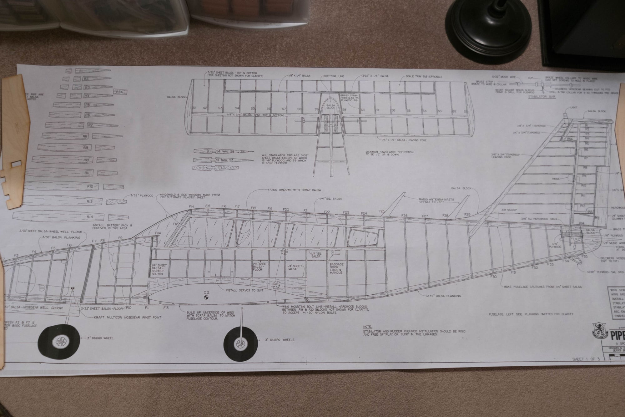
Ok I uploaded a copy of the plan maybe this will help with knowing exactly what I'm trying to do? The fuse tapers back and down in the front. Looks like some people somehow supported the upper and lower Keel? Having a hard time hope you guys can help now that you can see the plan??
hanks Bob
hanks Bob
04-24-2019, 08:14 AM
#10
I have to agree with Foodstick about there being too many formers. I went over to Outerzone and had a look at the plans and construction article. One option would be to source an "Adjusto-Jig". They are scarce but there are apparently a few out there. Failing that, you could recreate the function of an adjusto-jig without the adjusto by cutting a series of plywood slotted tongues and gluing them to a base along a straight datum line. The slots would have to be narrow enough to hold the "fuselage crutch" stringers in place while the formers and eventually the sheeting were glued in place. It would be necessary to be really accurate in locating and marking the position of the formers on the crutches and in locating the crutches in relation to one another. It might be easier to add a set of stingers at about the level of the fuselage floor and use them as a crutch for building the fuselage.
04-26-2019, 07:07 PM
#11

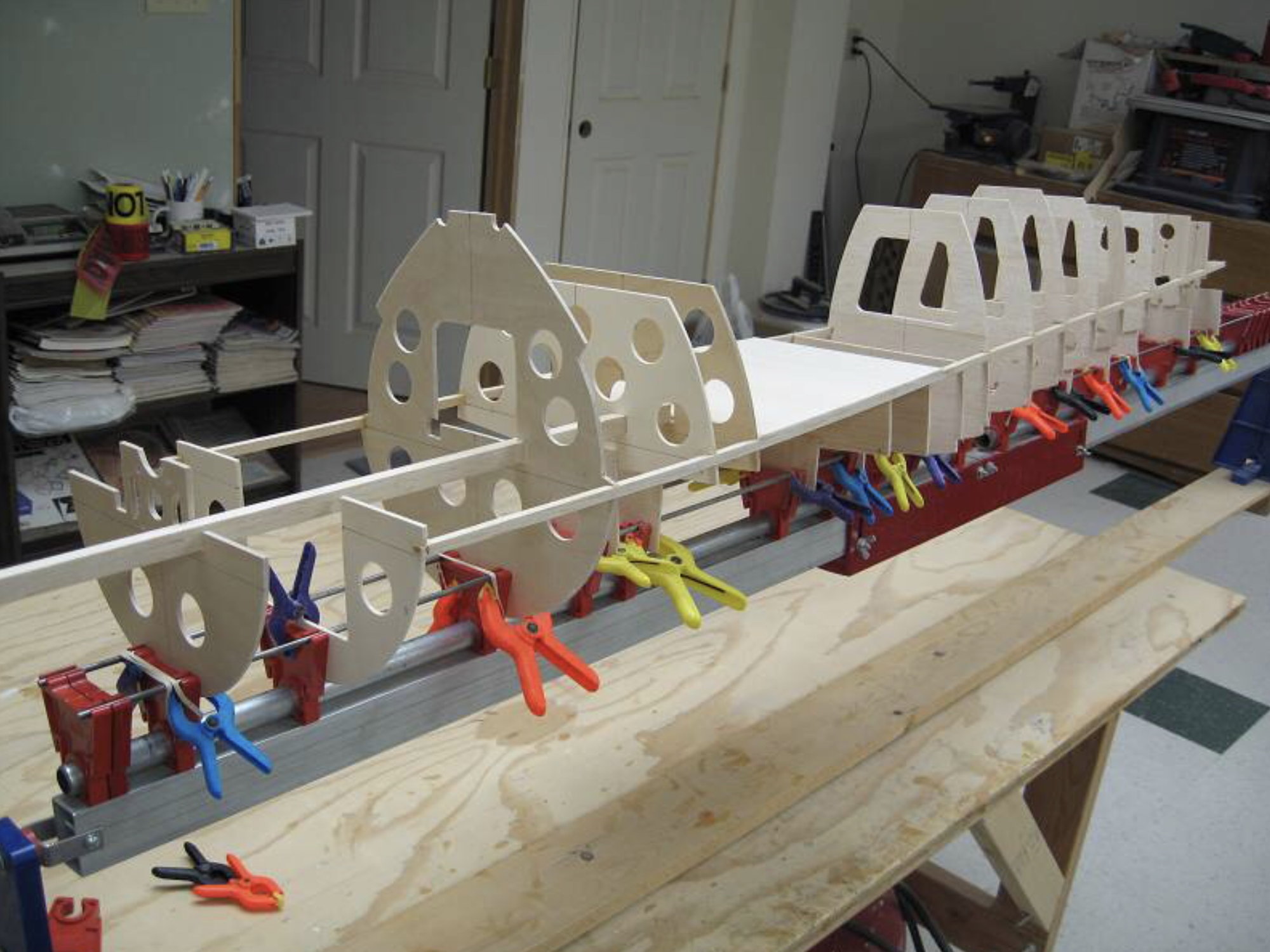
This is the approach I used to build my scratch designed Siemens Schuckert D-III.
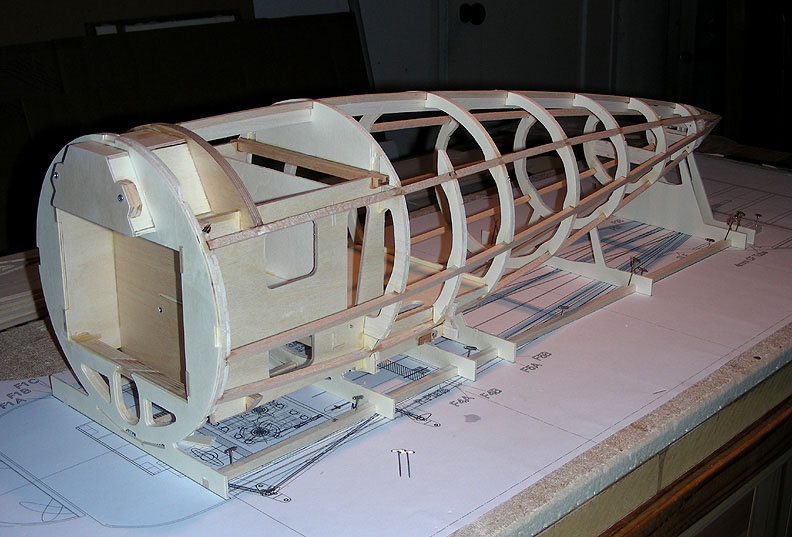
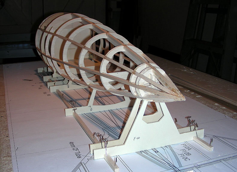
Some of the formers have "feet" that are pinned to the plan. These were NC cut with this feature but could also be accomplished with add-on pieces.
Very accurate and stable. Part of the sheeting is started before pulling the fuse off the board.
Some of the formers have "feet" that are pinned to the plan. These were NC cut with this feature but could also be accomplished with add-on pieces.
Very accurate and stable. Part of the sheeting is started before pulling the fuse off the board.
04-27-2019, 10:40 AM
#13
Thread Starter
My Feedback: (1)
Join Date: Dec 2010
Location: Pittsford, NY
Posts: 290
Likes: 0
Received 0 Likes
on
0 Posts
Yes I know a few ribs there haha. Yes I was trying to buy the Adjusto Jig but cant fine one from anyone. Any more idesa step by step on making a proper jig for the plan you see here? Just got the 2 Saito 82 4 Strokes for it.
Thanks guys let me know him him ideas??
Thanks guys let me know him him ideas??
04-27-2019, 01:02 PM
#14
Thread Starter
My Feedback: (1)
Join Date: Dec 2010
Location: Pittsford, NY
Posts: 290
Likes: 0
Received 0 Likes
on
0 Posts
Forgot you asked about is this the specific model yes these are the plans. Had the plans for 20 plus years ansd have several twins thought this would be fun.
Bob
Bob
04-28-2019, 05:09 AM
#15
Ok just throwing this idea out after reading the build article. Looking at the pictures, I see how the adjusto-jig works for this build. So a substitute adjusto-jig.
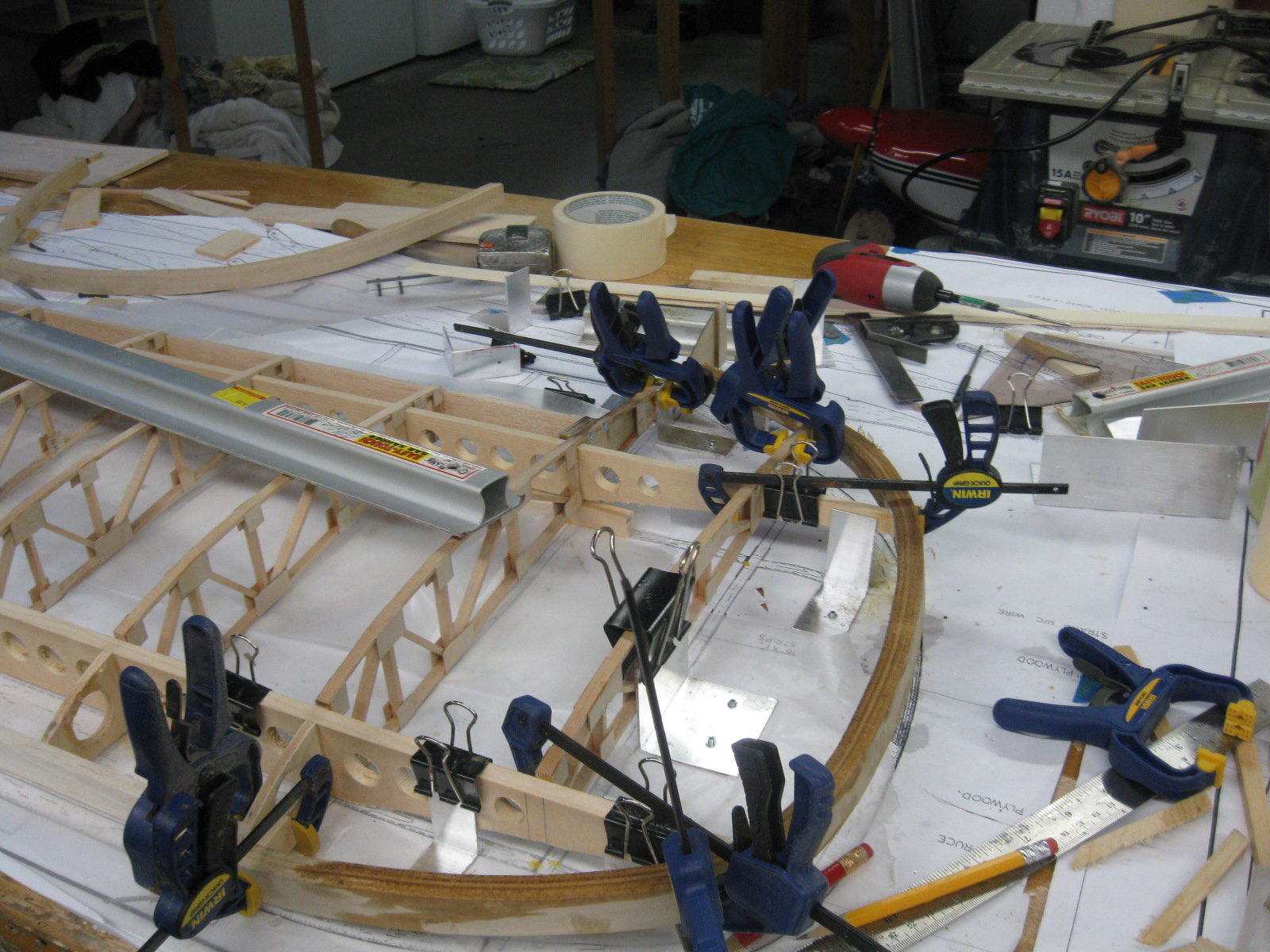
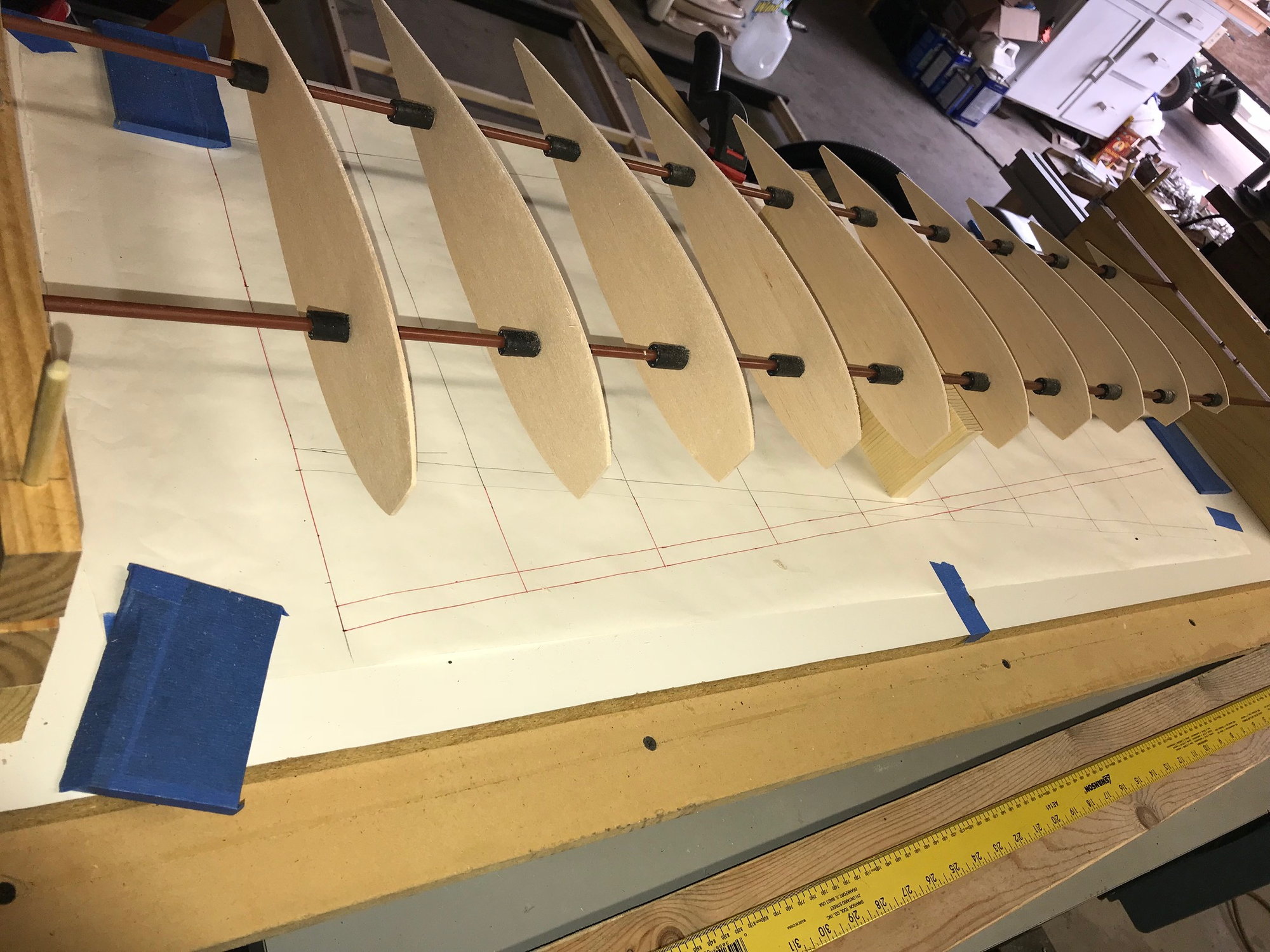
I made this wing jig and used automotive fuel tubing as squaring and alignment support. After the wing is built the tubing just pops off the rod. The rods can then be pulled from the wing.
Now picture the wing ribs as fuselage supports pictured in the article. Add a third rod inches below and centered between the two top rods. This rod helps you plumb the supports. The fuel tubing can be GOOP glued to the rods once the fuselage supports are in position, squared and plumb.
I think it may work.
04-28-2019, 07:01 AM
#16
Heliman, it wouldn't be that hard to add feet ala Alan Flowers. Draw a datum through the length of the plan. Transfer that datum line to each of the formers according to their position in the model.Draw a parallel line on the plans underneath the model. Use the distance between the two lines to determine how long the legs should be. Note how Alan stabilizes his feet. Once you have added enough stringers/sheeting to locate and stabilize all of the formers then you can trim away the feet and proceed as usual.
 04-29-2019, 08:04 AM
#19
Hmmm, given that the metal all appears to be stock sizes it probably wouldn't be that hard to recreate the jig. The plastic parts could be 3-D printed.
05-14-2019, 11:08 AM
#20
Thread Starter
My Feedback: (1)
Join Date: Dec 2010
Location: Pittsford, NY
Posts: 290
Likes: 0
Received 0 Likes
on
0 Posts
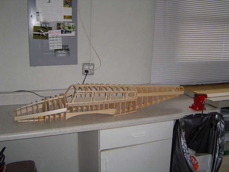
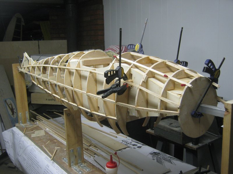
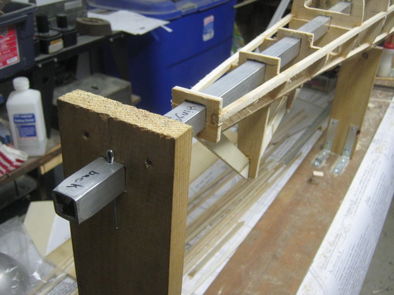
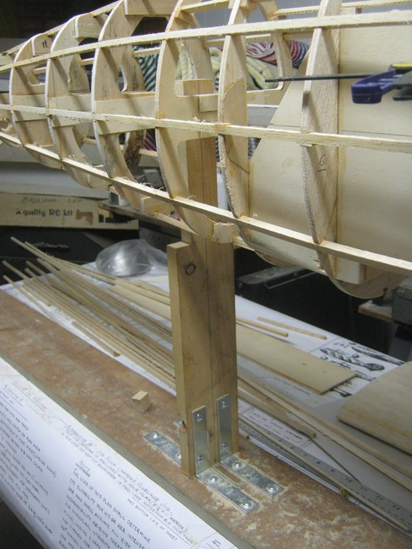
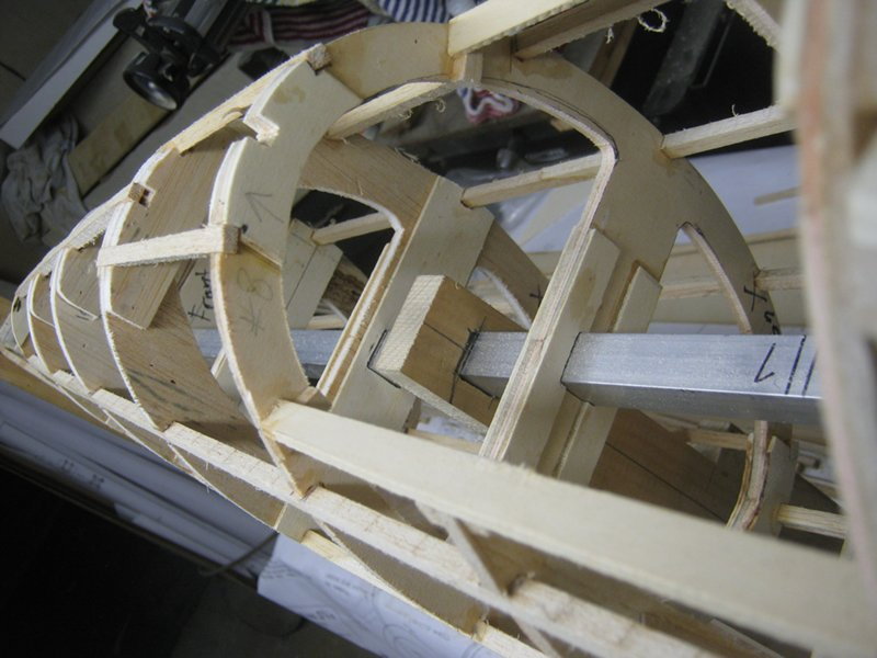
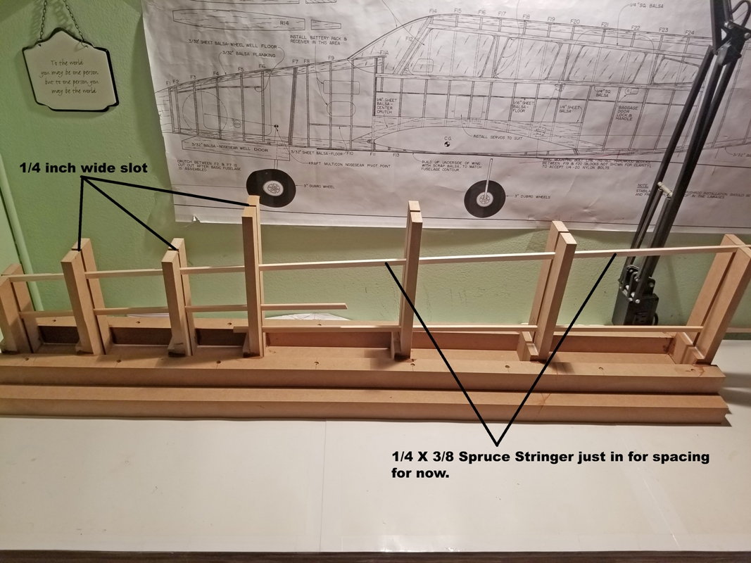
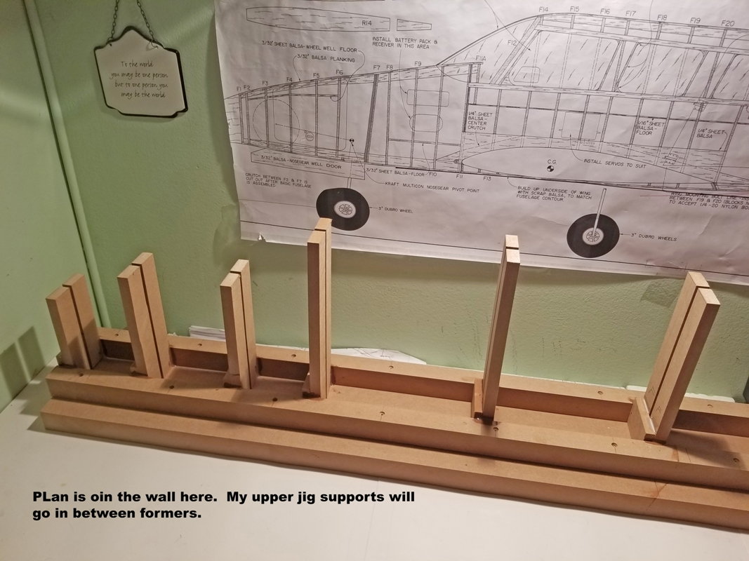
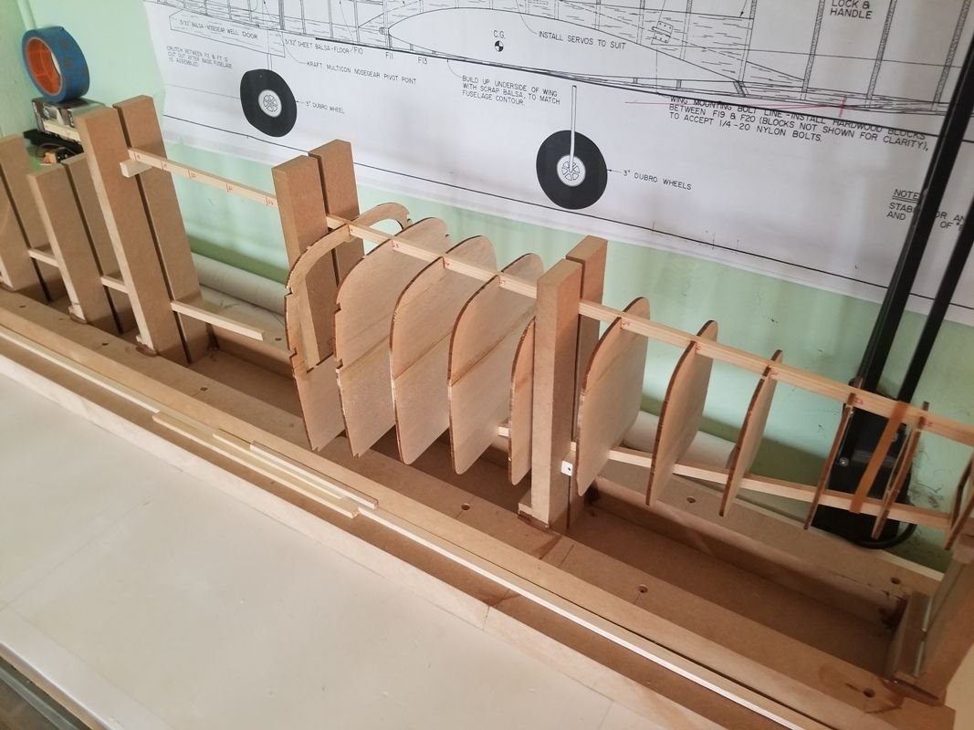
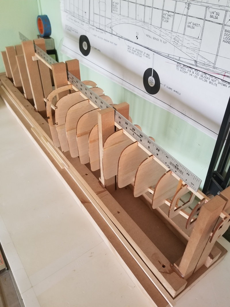
Okay here's the completed jig. This should not warp. There are quarter inch slots for me to slide down my 1/4 by 3/8 basswood strip. Also there's a few pictures I started putting in some former's just to see how things line up what you guys think? The plans are on the wall.

05-14-2019, 01:37 PM
#21
Looks like that dog'll hunt.
05-16-2019, 03:20 PM
#22
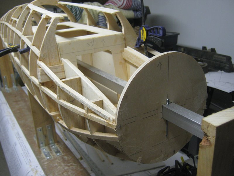
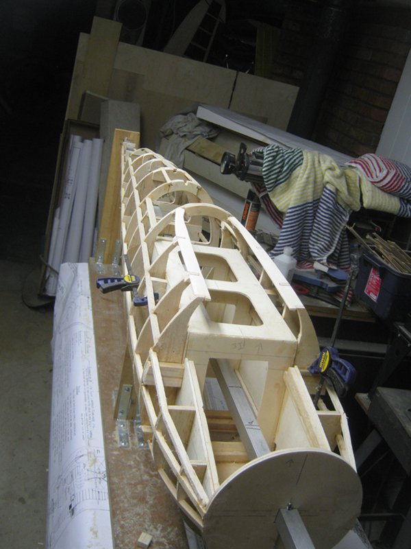
I know I mentioned that there were more than enough formers in there.. But don't get to far along in your build without opening some routes for your pushrods.. Unless you are mounting the servos in back.. (you will still need to run wires somehow...)
I have made similar mistakes in wings before
I have made similar mistakes in wings before
05-21-2019, 09:10 AM
#23

My Feedback: (19)
We affectionately refer to that as "old school". Unless building the tail heavy on purpose, all those tail cone formers could have been sawed out in the center. There are also lots of ribs in the horizontal stab, elevator fin and rudder. I can't imagine them all being necessary.
