


Seagull models
 12-21-2014, 02:06 PM
#26

My Feedback: (11)
Join Date: Jan 2002
Location: Panama City Beach,
FL
Posts: 783
Likes: 0
Received 0 Likes
on
0 Posts
Thanks Martin. When I saw the yellow one on the Seagull FB page I assumed that was on unfinished prototype with only half of the markings applied. I'm surprised they are shipping them that way. We would love to see more pictures of your plane....thanks. From what I see, this is still a must have even with the stretched cowl which I think is better looking than the full-size cowl. Hahahaha.
 12-24-2014, 01:00 AM
#27
Member

Join Date: Oct 2006
Location: Dubai, UNITED ARAB EMIRATES
Posts: 40
Likes: 0
Received 2 Likes
on
2 Posts
Hi Dave
I am quite busy these days. Will do some postings in the next few days!
As for the Airfoil I will have to disappoint you!
It is a fully symmetric one with a thickness of something between 11% - 12%!
So rather thin.
But the wing loading will be low so I would think it should work well for you!?
I am in the final stage of the building now. Depending on the battery it weighs between 5 to 5,2 kgs.
More then I was hoping for but still very good!?
Happy Holidays!!!
Martin
12-26-2014, 03:56 AM
#28
Member
Join Date: Oct 2006
Location: Dubai, UNITED ARAB EMIRATES
Posts: 40
Likes: 0
Received 2 Likes
on
2 Posts
Hi guys
So, I finally got some time to share my build with you.
For me, starting a new project always starts with a fair amount of thinking. It can easily take hours and days before I get started on the actual build.
After some research it was clear to me:
- If at all possible weight reduction behind the CG is essential (the model seems to be rather tail heavy!)
- Power train must be as forward as possible.
- Design needs a complete make over since the "Swiss" decals that are applied are just wrong!
- I set myself the goal of a final take off weight of 5kgs (≈ 11lbs)
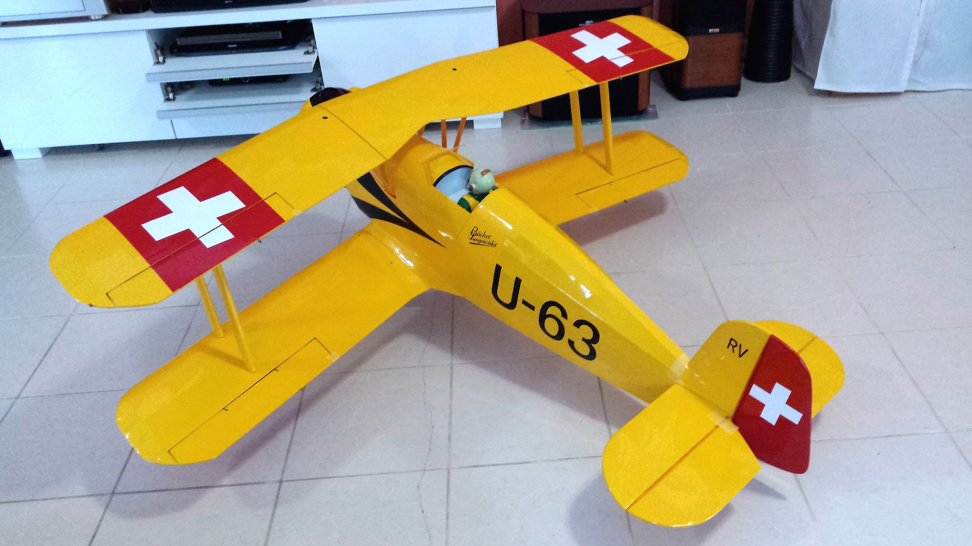
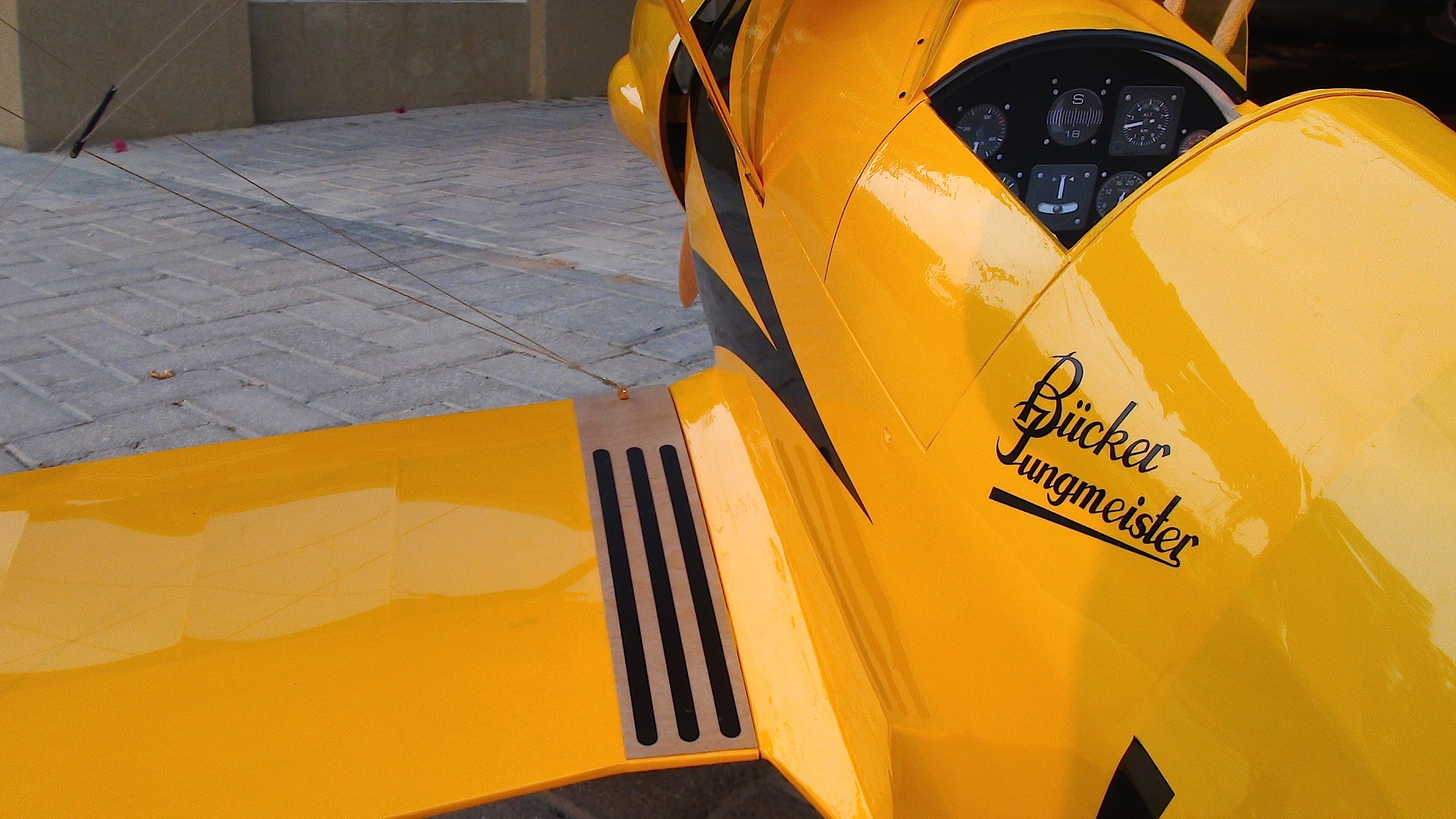
I started by giving this nice bird the REAL Swiss design it deserves!
With only the engine cowling remaining (needs repainting) it looked like this:

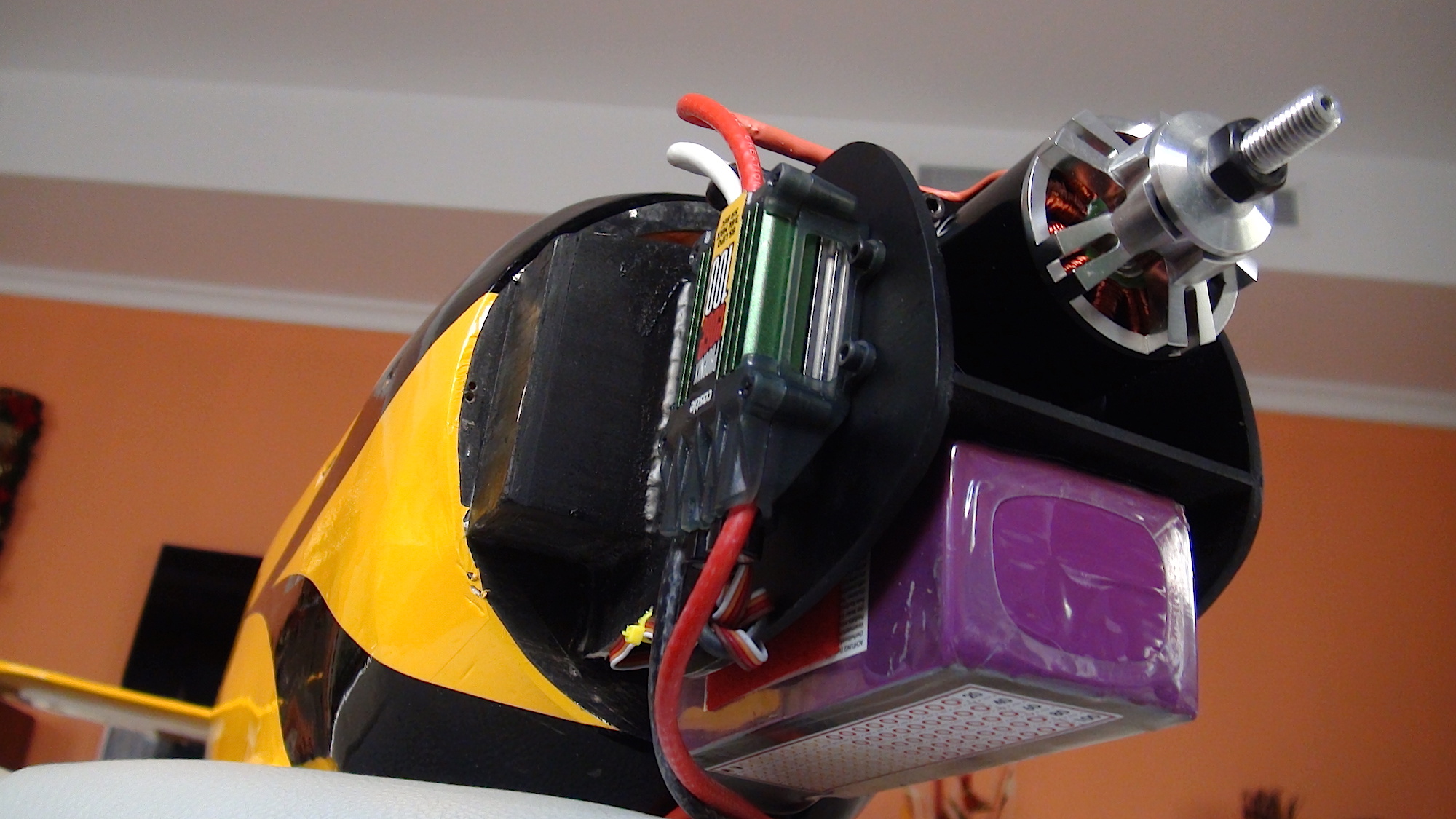
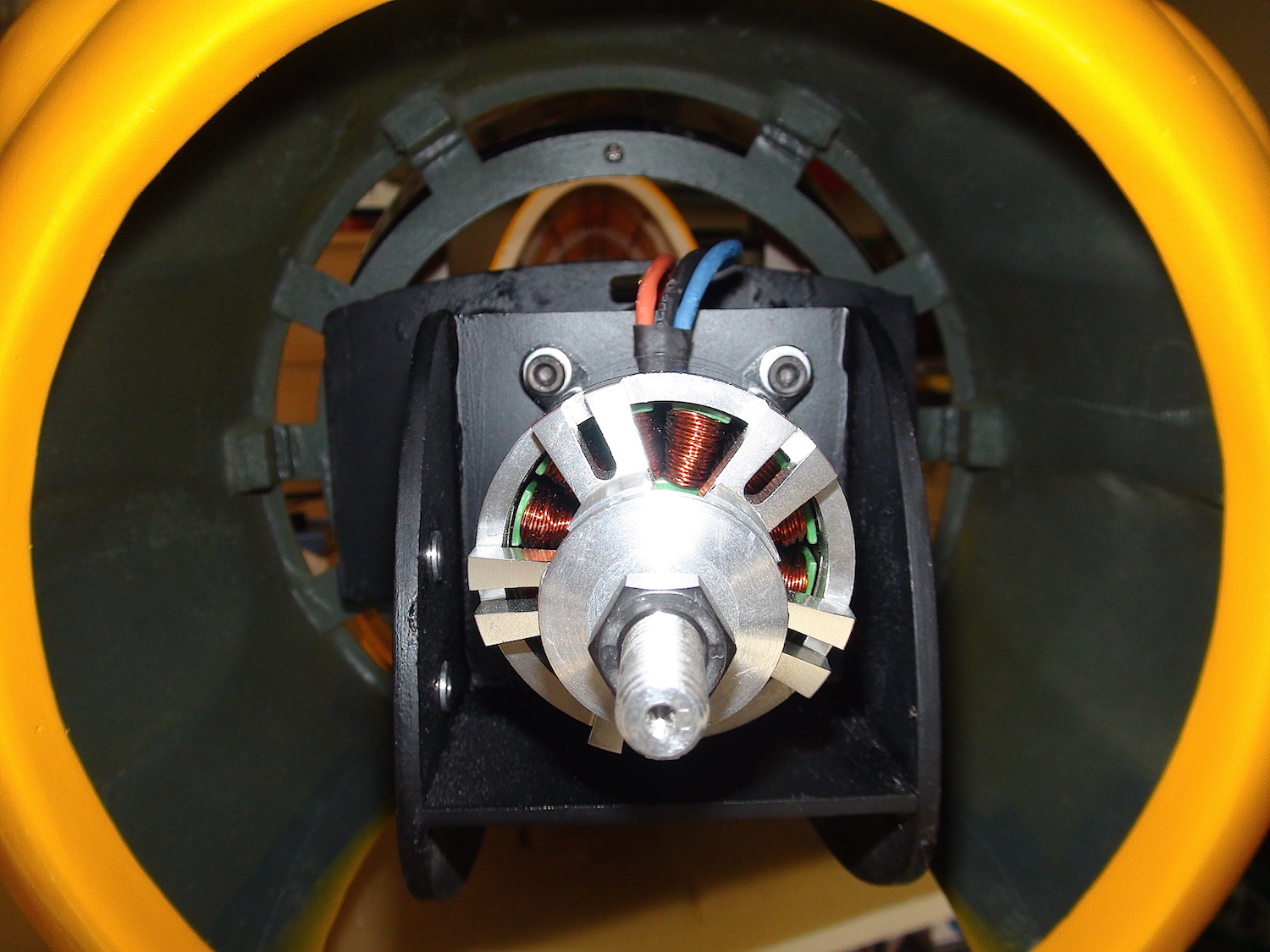
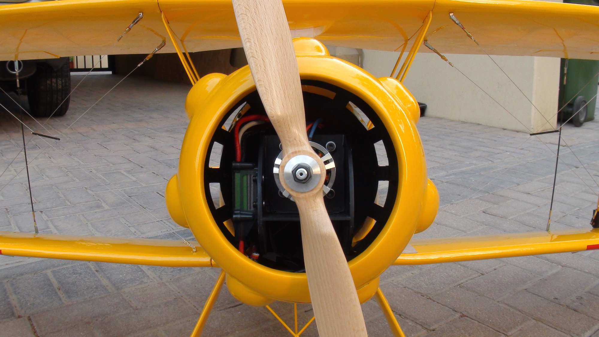
In doing this I had plenty of time to think about the installation of motor, battery and ESC.
I had to come up with a concept that integrated these components and brought them right behind the prop.
It finally looked like this:
Installed:

The push rods did not really please me! They did not move properly and were not precise!
The only solution was to put the servos where they belong...in the back.
But wait, didn't the guy say he wanted to reduce weight in the back? Wouldn't that contradict the idea?
Well...yes and no is the answer?!
After I removed all the push rods (4 pieces!) I did weigh them. A whopping 100r!!
The servos did weight around 28r each including the frame. There is also some wires of course.
But all in all I would say this reduced weight and did not spoil the CG!?
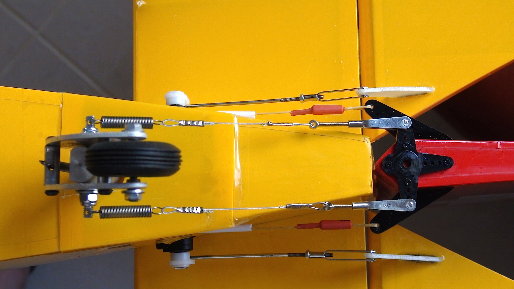
To align the servos with the horns of the elevators, and to make them disappear I had to embed them into the fuselage.
The rudder became a good old pull pull system with Kevlar thread.

So far so good....
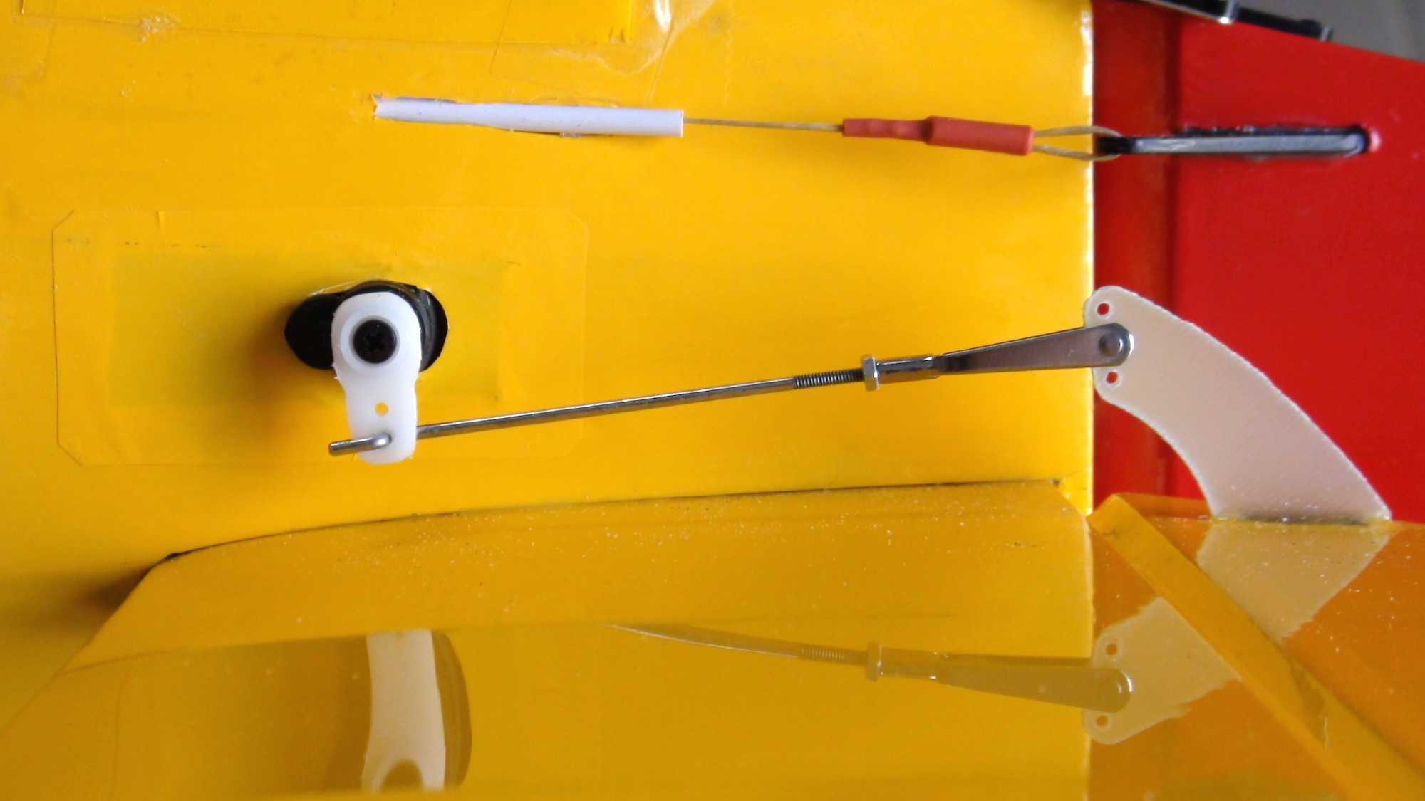
To steer the tail wheel there was also a push rod, which I removed already.
I came up with this solution:
I mounted a servo arm on the rudder. The bolt of the tail wheel unit was removed and replaced with a wider one that had holes drilled at each end.
Two steel wires with springs, connected between the horn and the tail wheel now move that unit.
Wether this will work properly and sustain the forces remains to be tested.
In any case I still have the option to tighten the clevises to get a stiffer setup.
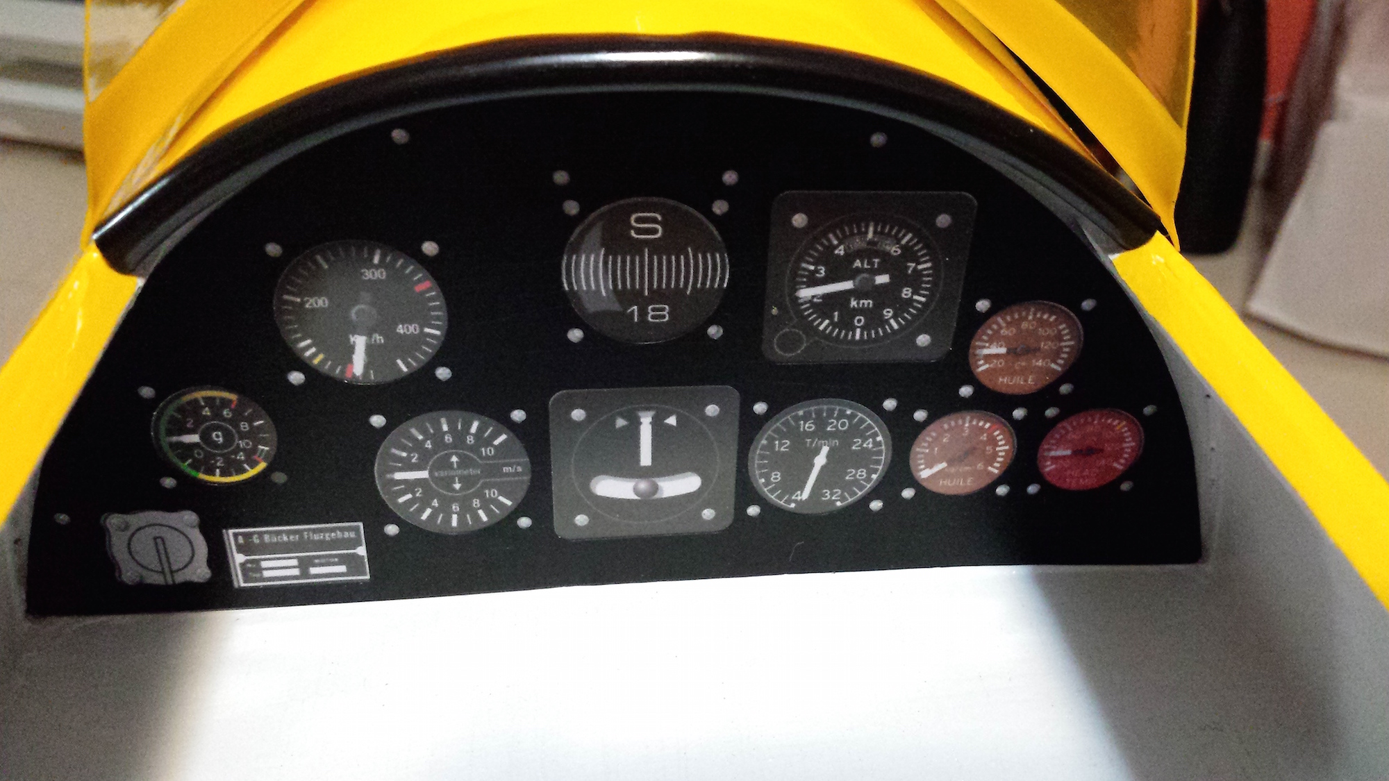
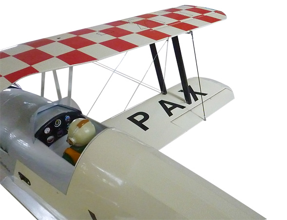
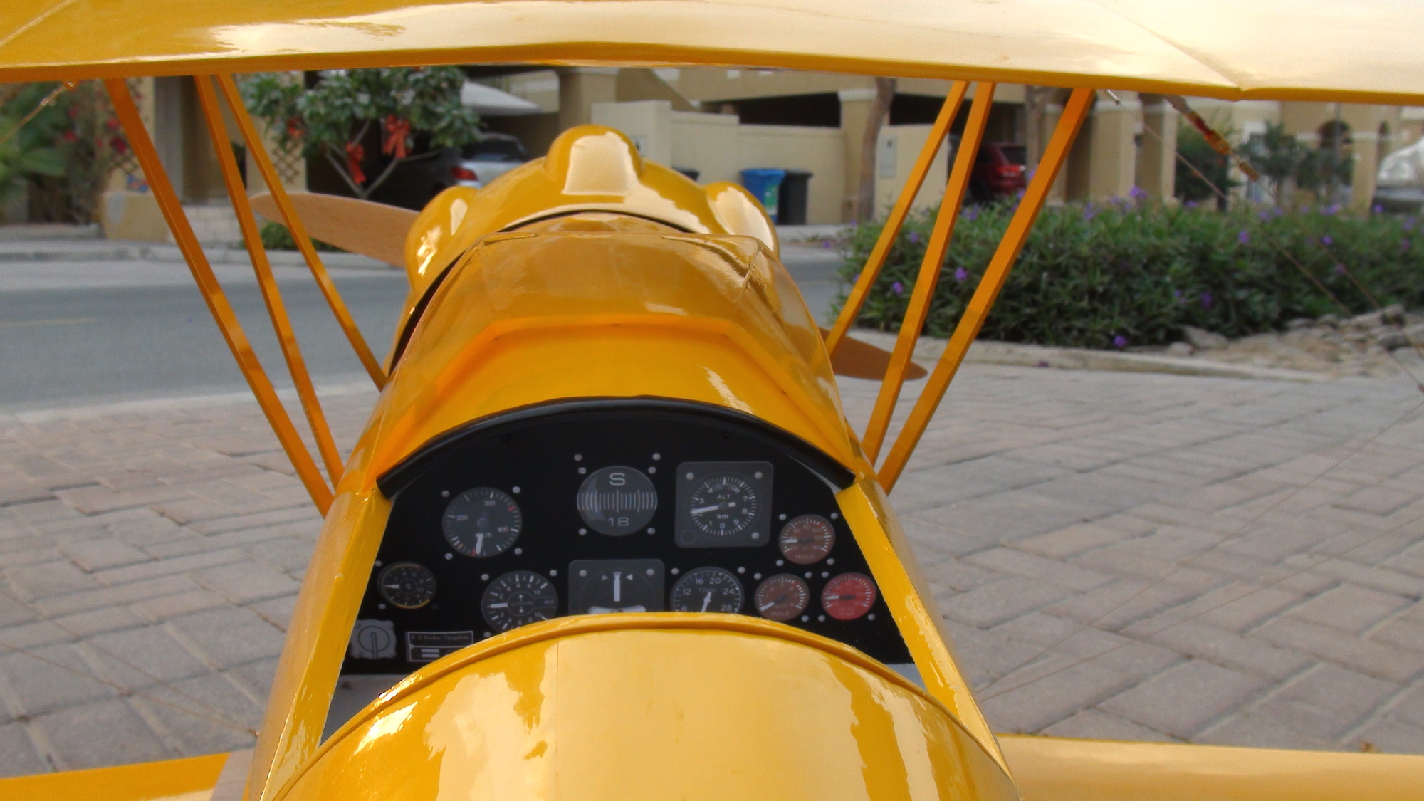
Since I was in the mood I decided to spend some time to give this bird a proper cockpit. After all, it is open and very much visible!
A bit of work with the laser printer, my vinyl cutter, assembled with a clear PVC in between, this is what you will look at now:
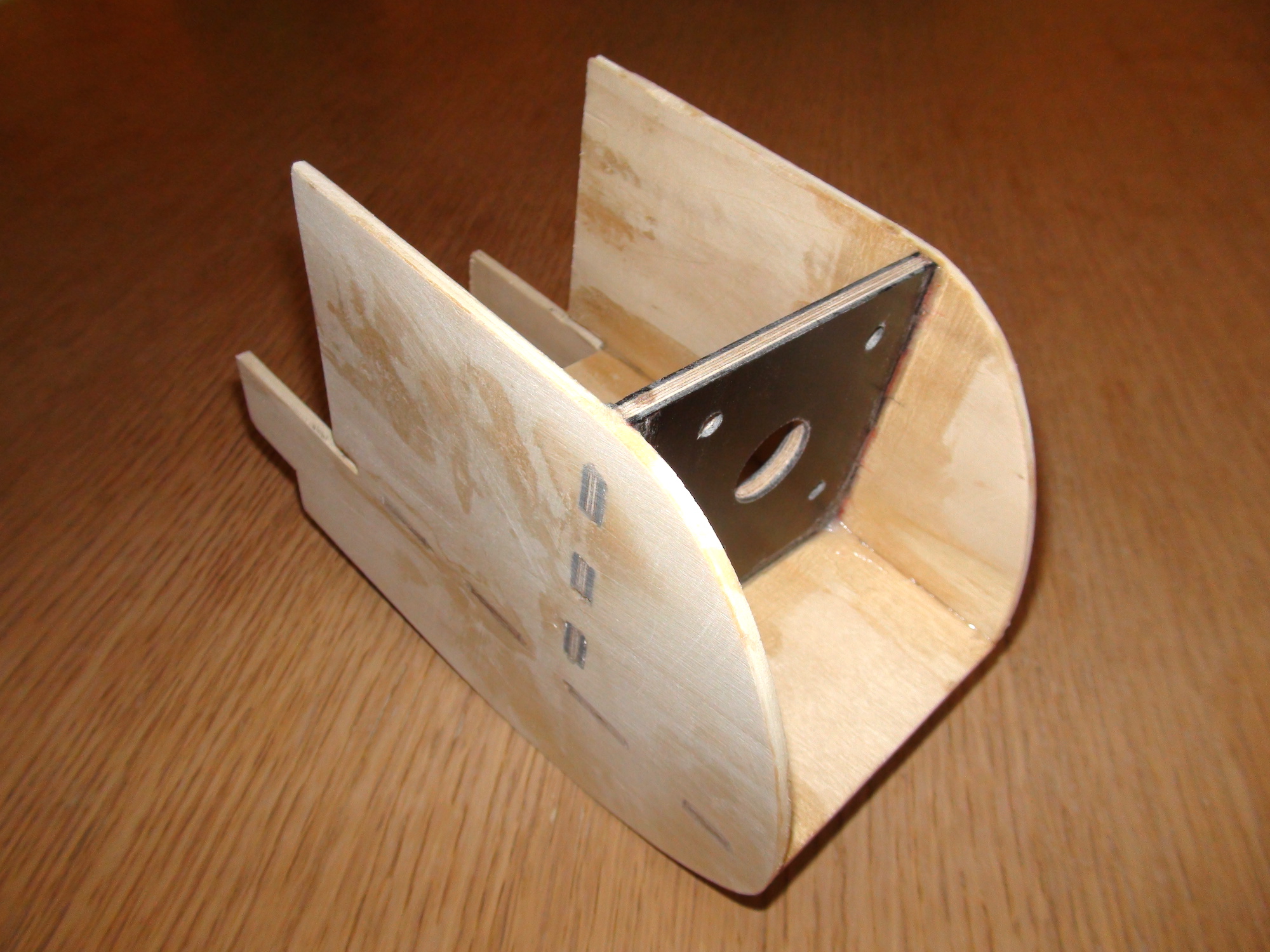
Mounting all the components of the power train in the cowling was calling for some sort of access to it.
It took me quite a while to decide what the best way would be to deal with this.
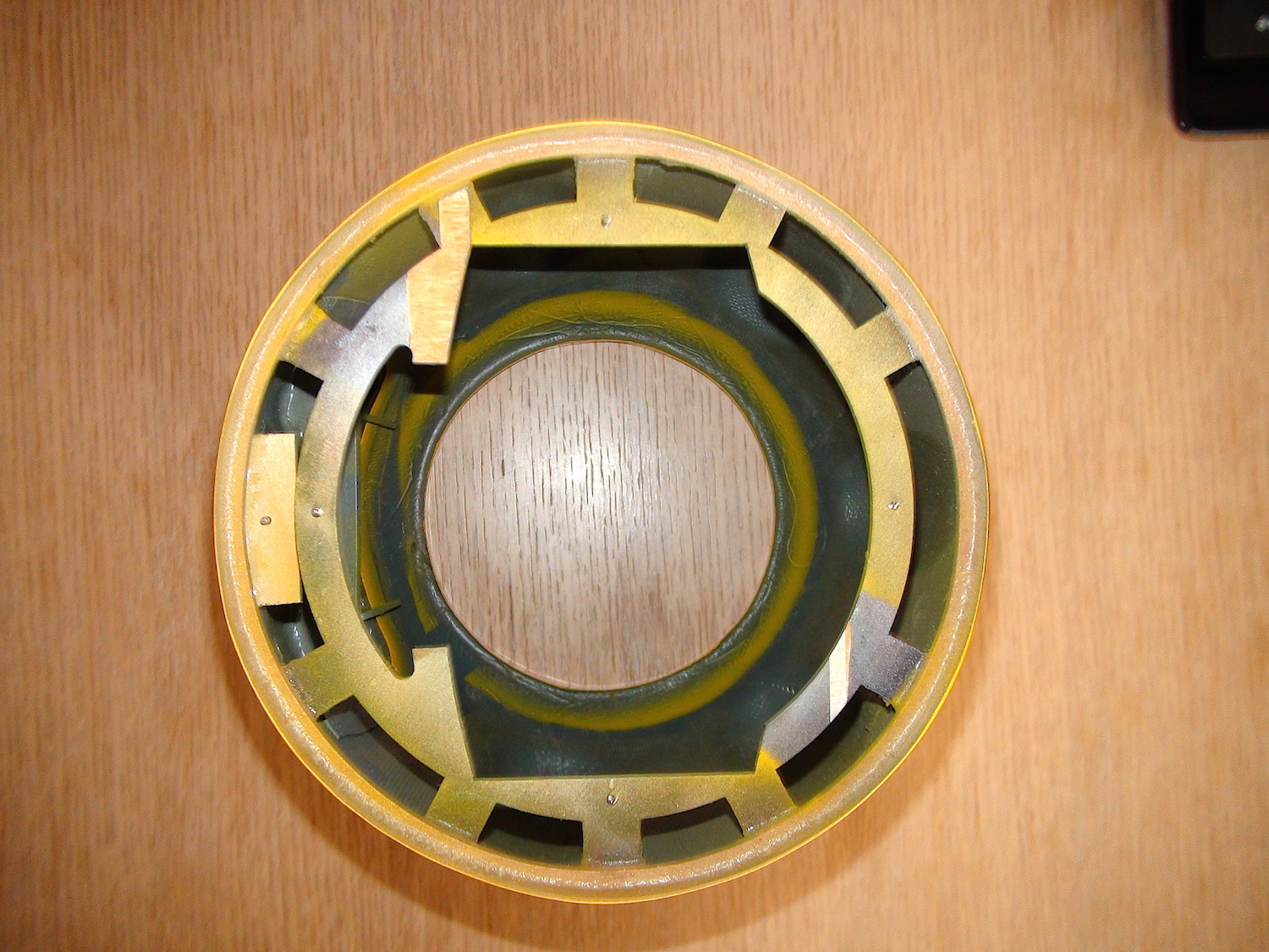
First I wanted to divide the cowling into 2 parts, but then I decided to make an access hatch.
The cowling was rather wobbly. So I fabricated a ring out of 3mm ply wood with a depth of about 6mm.
The outer diameter being the inner diameter of the cowling so it would fit snuggly into it.
Originally there was a wooden ring with some sort of supports glue to it that was bolted with 4 bolts to the fuselage.
Then the cowling would have to be screw onto these supports.
As a next step I glued my ply wood ring together with the existing ring into the cowling.
Now the whole unit became very stiff and strong. With access from the front the cowling can now be bolted with the original 4 bolts
to the fuselage with NO screws visible from outside!
Sounds complicated?
Pictures say more then words...specially if the authors mother tongue is not English!")
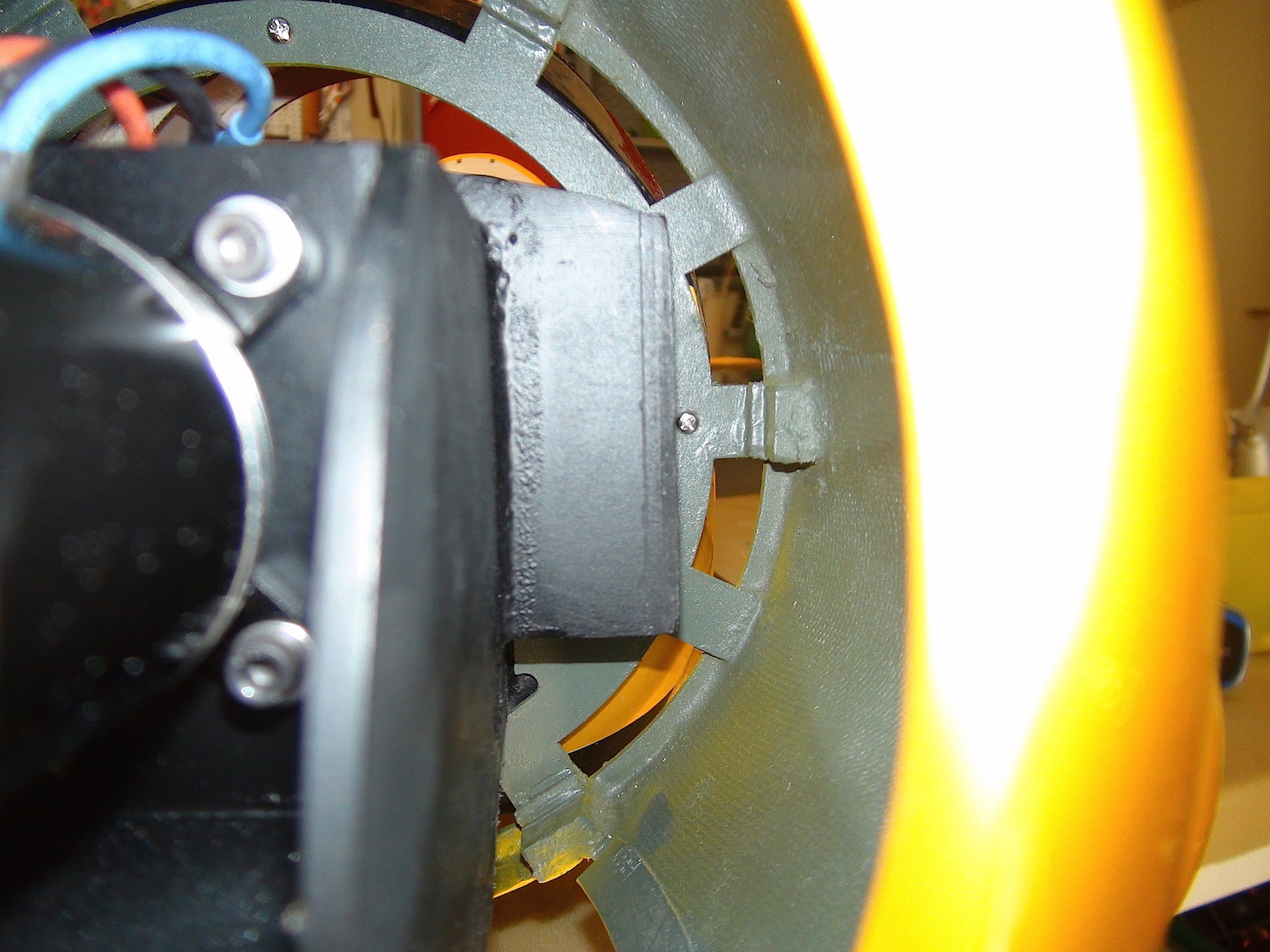
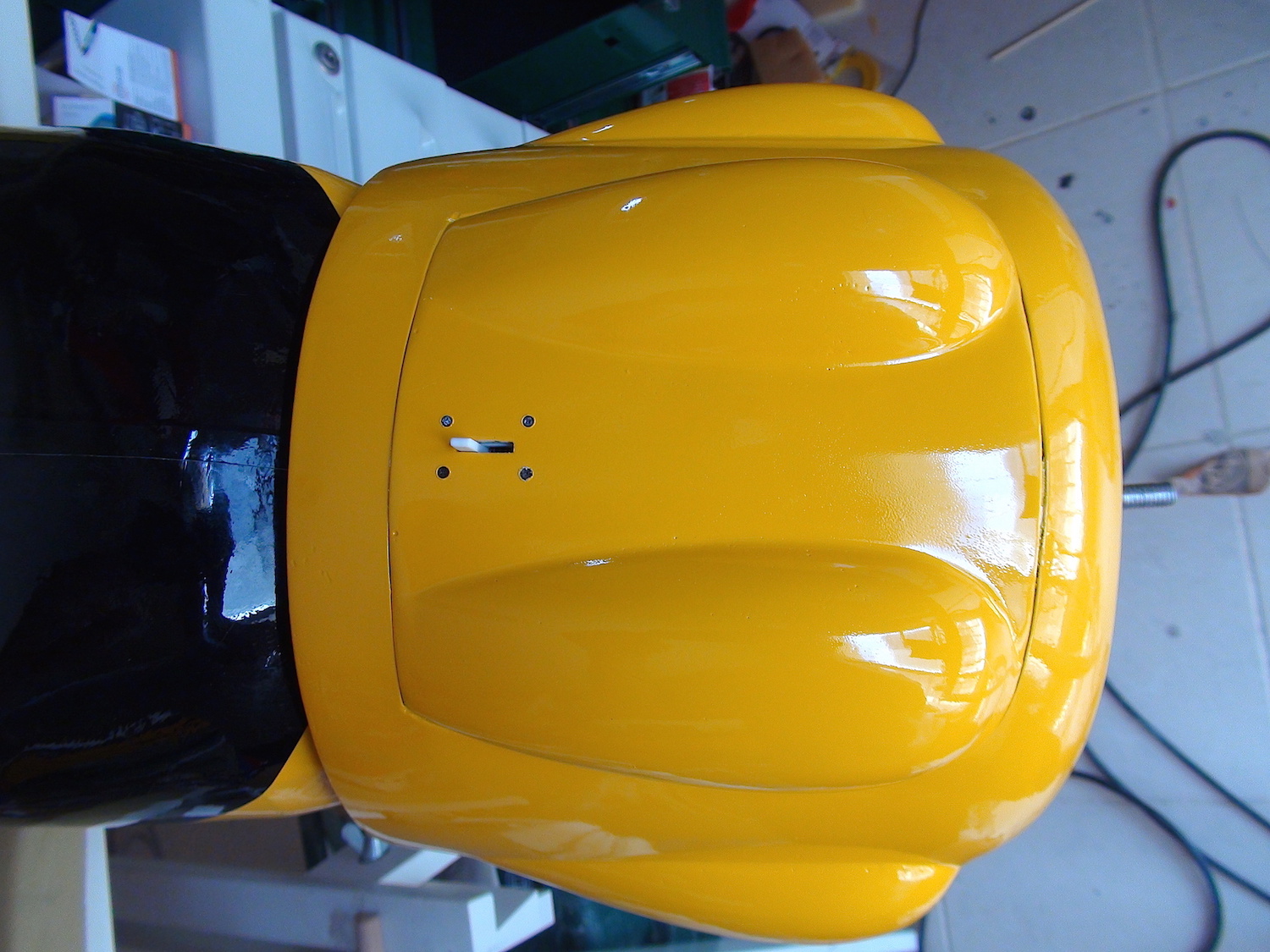
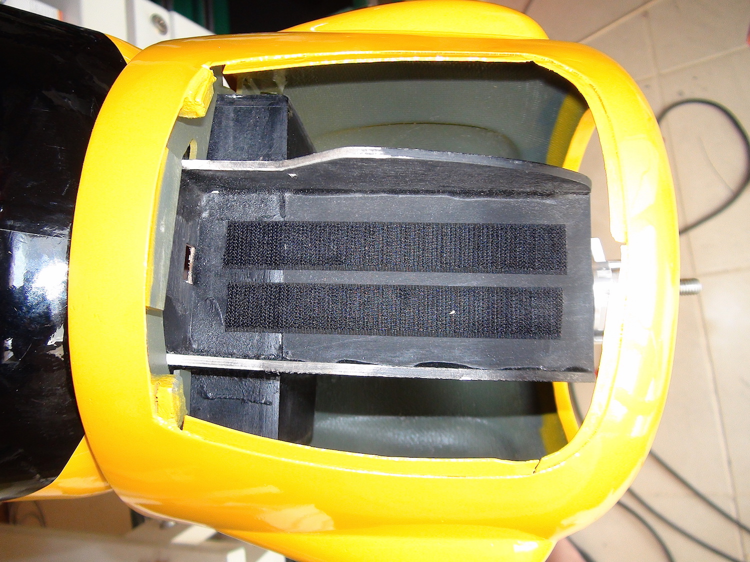
Opening the hatch gives access to the battery tray:
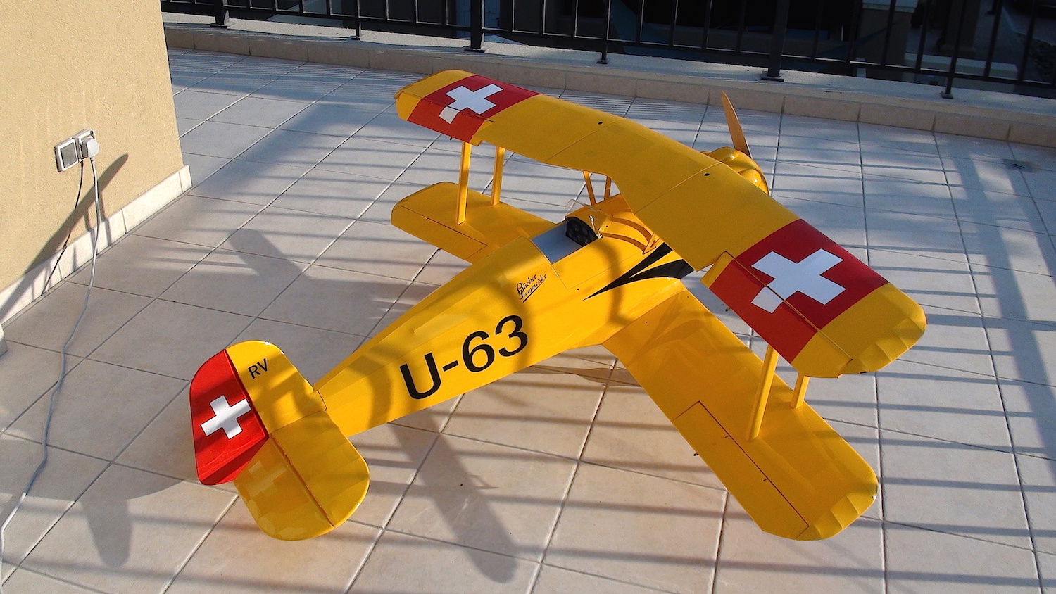
Meanwhile the cowling was repainted and it was time to assemble the model once again to see what it looks like.
I was VERY pleased with what I saw!

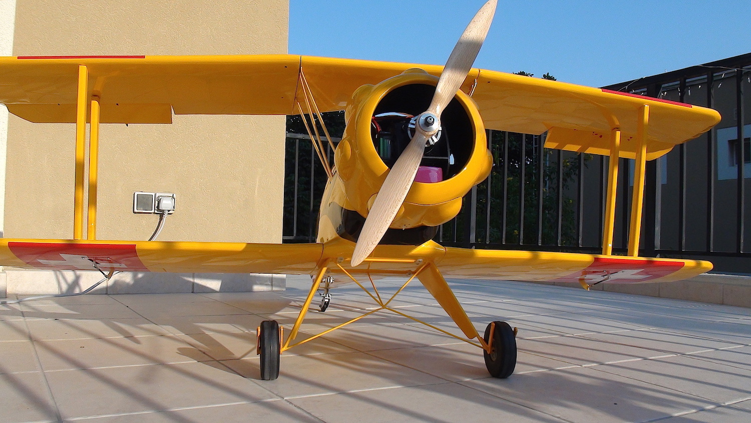
To be continued...
So, I finally got some time to share my build with you.
For me, starting a new project always starts with a fair amount of thinking. It can easily take hours and days before I get started on the actual build.
After some research it was clear to me:
- If at all possible weight reduction behind the CG is essential (the model seems to be rather tail heavy!)
- Power train must be as forward as possible.
- Design needs a complete make over since the "Swiss" decals that are applied are just wrong!
- I set myself the goal of a final take off weight of 5kgs (≈ 11lbs)
I started by giving this nice bird the REAL Swiss design it deserves!
With only the engine cowling remaining (needs repainting) it looked like this:
In doing this I had plenty of time to think about the installation of motor, battery and ESC.
I had to come up with a concept that integrated these components and brought them right behind the prop.
It finally looked like this:
Installed:
The push rods did not really please me! They did not move properly and were not precise!
The only solution was to put the servos where they belong...in the back.
But wait, didn't the guy say he wanted to reduce weight in the back? Wouldn't that contradict the idea?
Well...yes and no is the answer?!
After I removed all the push rods (4 pieces!) I did weigh them. A whopping 100r!!
The servos did weight around 28r each including the frame. There is also some wires of course.
But all in all I would say this reduced weight and did not spoil the CG!?
To align the servos with the horns of the elevators, and to make them disappear I had to embed them into the fuselage.
The rudder became a good old pull pull system with Kevlar thread.
So far so good....
To steer the tail wheel there was also a push rod, which I removed already.
I came up with this solution:
I mounted a servo arm on the rudder. The bolt of the tail wheel unit was removed and replaced with a wider one that had holes drilled at each end.
Two steel wires with springs, connected between the horn and the tail wheel now move that unit.
Wether this will work properly and sustain the forces remains to be tested.
In any case I still have the option to tighten the clevises to get a stiffer setup.
Since I was in the mood I decided to spend some time to give this bird a proper cockpit. After all, it is open and very much visible!
A bit of work with the laser printer, my vinyl cutter, assembled with a clear PVC in between, this is what you will look at now:
Mounting all the components of the power train in the cowling was calling for some sort of access to it.
It took me quite a while to decide what the best way would be to deal with this.
First I wanted to divide the cowling into 2 parts, but then I decided to make an access hatch.
The cowling was rather wobbly. So I fabricated a ring out of 3mm ply wood with a depth of about 6mm.
The outer diameter being the inner diameter of the cowling so it would fit snuggly into it.
Originally there was a wooden ring with some sort of supports glue to it that was bolted with 4 bolts to the fuselage.
Then the cowling would have to be screw onto these supports.
As a next step I glued my ply wood ring together with the existing ring into the cowling.
Now the whole unit became very stiff and strong. With access from the front the cowling can now be bolted with the original 4 bolts
to the fuselage with NO screws visible from outside!
Sounds complicated?
Pictures say more then words...specially if the authors mother tongue is not English!
Opening the hatch gives access to the battery tray:
Meanwhile the cowling was repainted and it was time to assemble the model once again to see what it looks like.
I was VERY pleased with what I saw!
To be continued...
Last edited by martair; 12-26-2014 at 04:07 AM.
12-26-2014, 04:31 AM
#29
Member
Join Date: Oct 2006
Location: Dubai, UNITED ARAB EMIRATES
Posts: 40
Likes: 0
Received 2 Likes
on
2 Posts
Alright, here we go again
With the model assembled now, and pretty much everything installed in its place it was time to check the CG.
To balance the model on the safe side I needed the bigger battery, a 6S 5000mAh.
I originally planned to fly it without the wheel fenders first, but missing collars made me mount the brackets. These are quite heavy!
To my disappointment the model now weighed in at just over 5kgs with a few parts still missing!
I anticipate the flying weight will be around 5.15 - 5.2 kgs (11lbs 7oz)
There is still room for weight loss, specially if the CG proves to be too far in the front (which is what I guess!?)
So with the smaller battery and a few small tricks I will still be able to achieve the 5kgs.
It was now time for finishing off the model by installing the braces and flying wires.
First of all I seem to have only braces for the right wing, and second, the way this is meant to be done does not really work, at least not for me!
I was looking into other options and luckily I found in some local shop these:
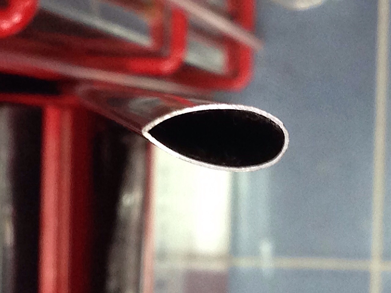
Tomorrow I will get back to work again and build brand new braces that will (hopefully!?) look much better!
The ones that come with the kit are way too chunky.
I will keep you up to date!
Cheers, Martin
With the model assembled now, and pretty much everything installed in its place it was time to check the CG.
To balance the model on the safe side I needed the bigger battery, a 6S 5000mAh.
I originally planned to fly it without the wheel fenders first, but missing collars made me mount the brackets. These are quite heavy!
To my disappointment the model now weighed in at just over 5kgs with a few parts still missing!
I anticipate the flying weight will be around 5.15 - 5.2 kgs (11lbs 7oz)
There is still room for weight loss, specially if the CG proves to be too far in the front (which is what I guess!?)
So with the smaller battery and a few small tricks I will still be able to achieve the 5kgs.
It was now time for finishing off the model by installing the braces and flying wires.
First of all I seem to have only braces for the right wing, and second, the way this is meant to be done does not really work, at least not for me!
I was looking into other options and luckily I found in some local shop these:
Tomorrow I will get back to work again and build brand new braces that will (hopefully!?) look much better!
The ones that come with the kit are way too chunky.
I will keep you up to date!
Cheers, Martin
Last edited by martair; 12-26-2014 at 06:12 AM.
12-30-2014, 01:09 PM
#30
Member
Join Date: Oct 2006
Location: Dubai, UNITED ARAB EMIRATES
Posts: 40
Likes: 0
Received 2 Likes
on
2 Posts
I did spend a whole day producing the new braces and then install the flying wires.
I think the result is not bad at all!
Die old ones were 28gr, the new ones only 12gr!
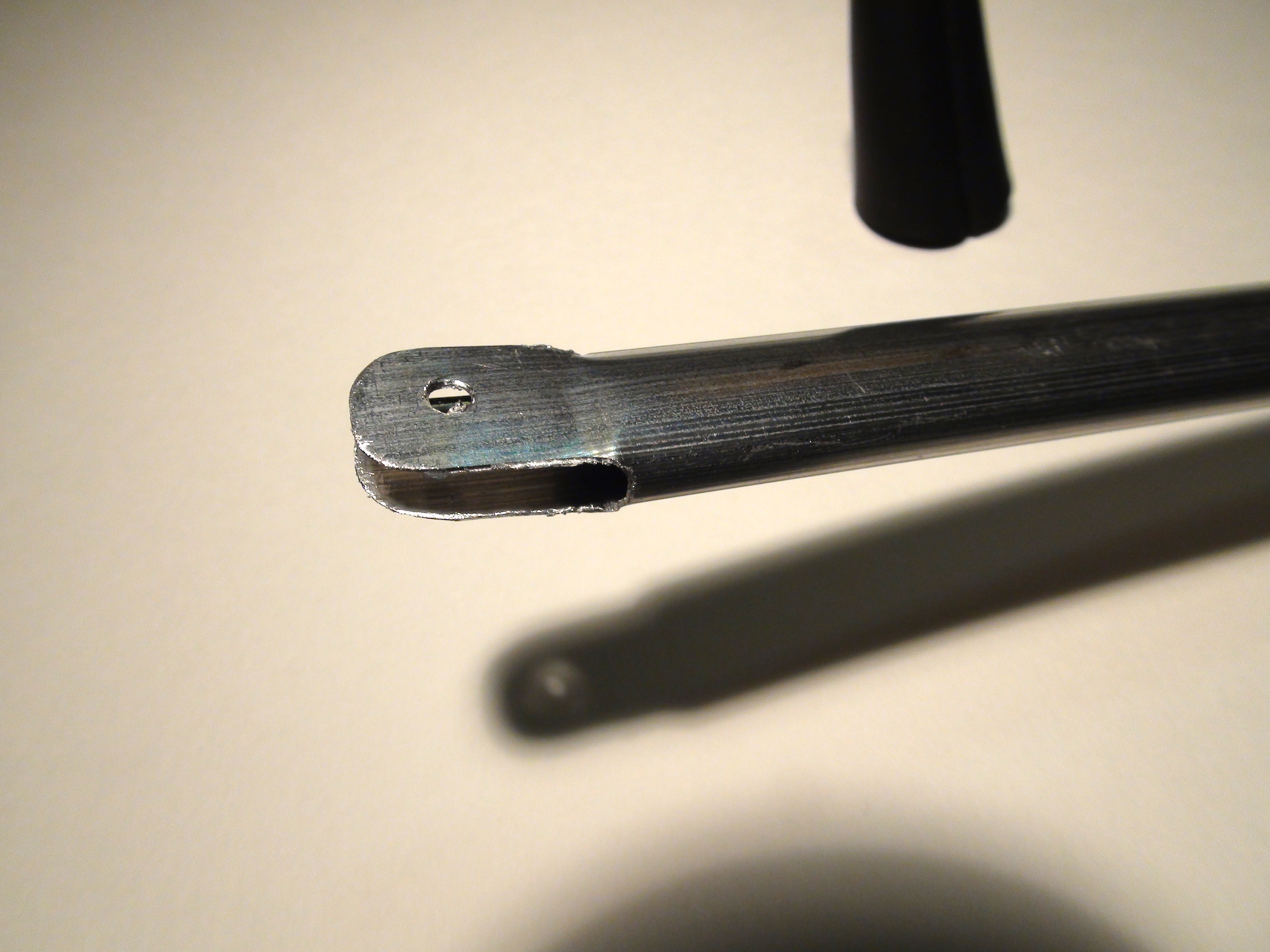
I just opened up the end and filed it to shape.
Then I covered them with Oracover and bolted them in place.
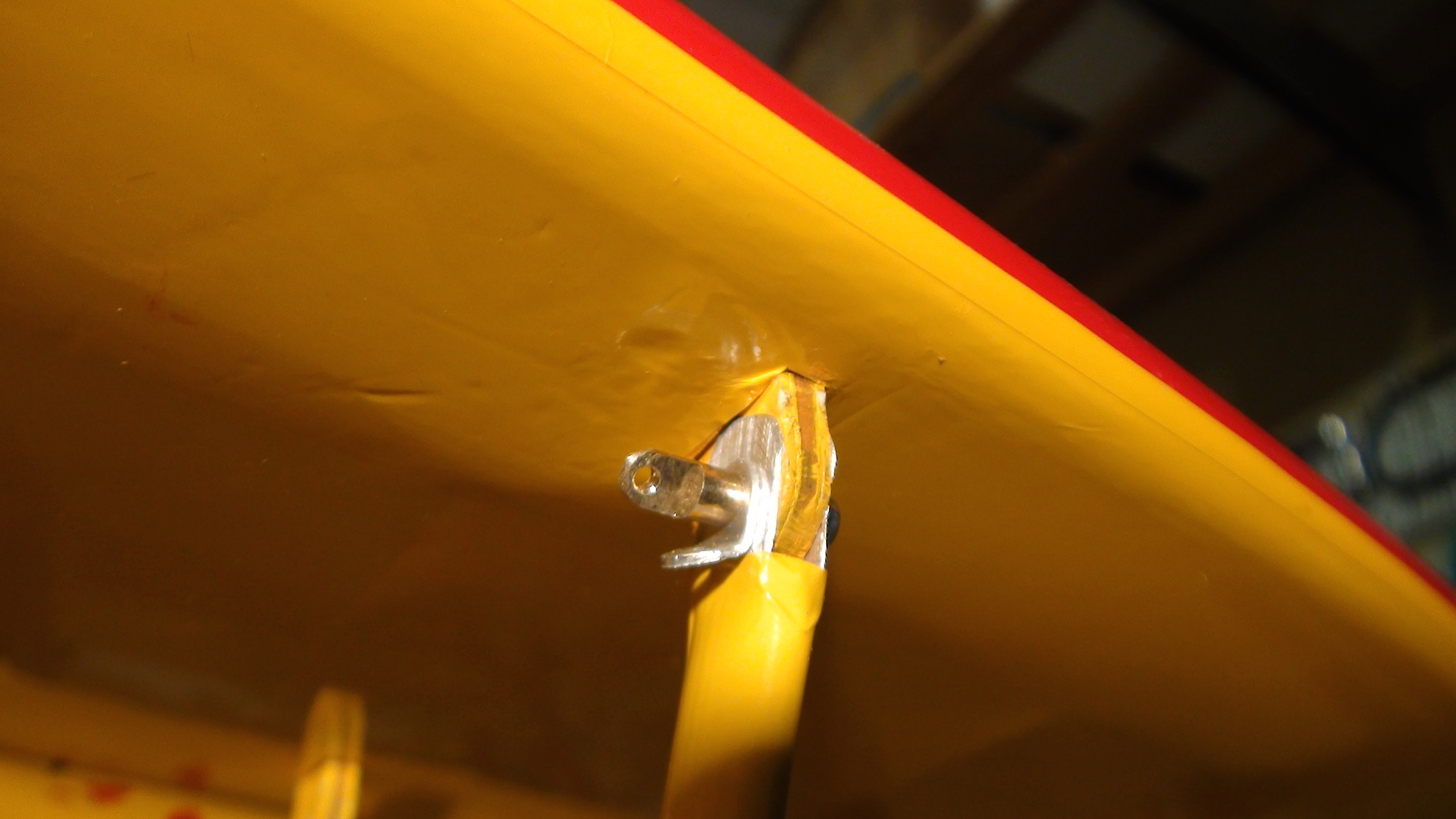
The flying wires were wrong! They ran parallel from the front lower wing root to the front upper brace, and the same in the back.
That was of course not scale!
What they should be is this:
- From the lower front wing root 2 wires go to the upper braces, forward and back each
- From the lower brace 2 wires go to the upper forward and aft wing root
I don't know if what I am describing makes sense, but pictures say more then words:
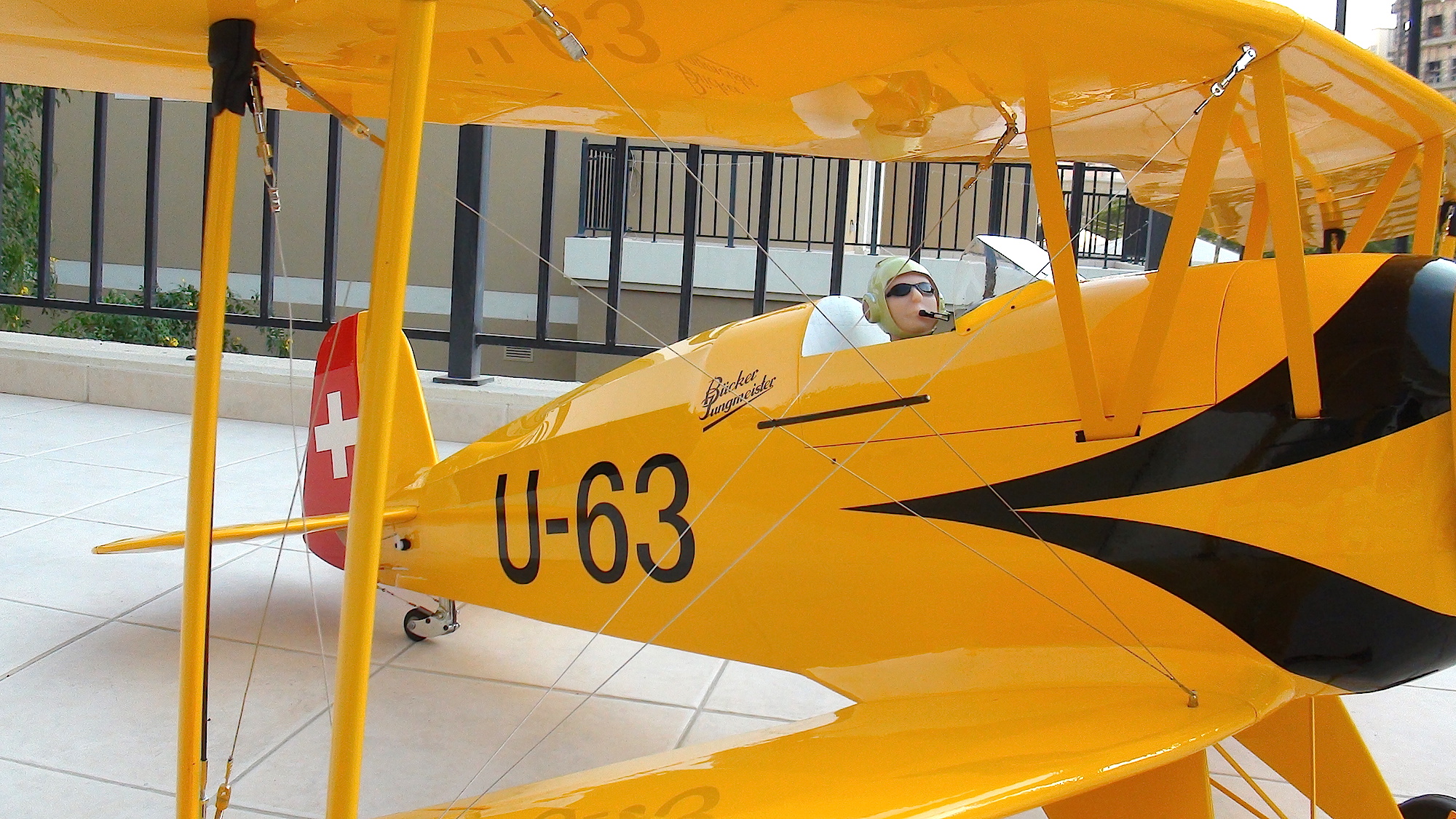
The pilot has a critical view as well but seems to be happy with it!
In the same move I also added the braces that hold the wires together where they cross in the middle.
A little scale detail that really makes a difference!
The model was now complete and anxiously I went to weigh it.
The scale showed 5095 grams (11lb 3.7oz). I am happy with this!
To be continued.....
I think the result is not bad at all!
Die old ones were 28gr, the new ones only 12gr!
I just opened up the end and filed it to shape.
Then I covered them with Oracover and bolted them in place.
The flying wires were wrong! They ran parallel from the front lower wing root to the front upper brace, and the same in the back.
That was of course not scale!
What they should be is this:
- From the lower front wing root 2 wires go to the upper braces, forward and back each
- From the lower brace 2 wires go to the upper forward and aft wing root
I don't know if what I am describing makes sense, but pictures say more then words:
The pilot has a critical view as well but seems to be happy with it!
In the same move I also added the braces that hold the wires together where they cross in the middle.
A little scale detail that really makes a difference!
The model was now complete and anxiously I went to weigh it.
The scale showed 5095 grams (11lb 3.7oz). I am happy with this!
To be continued.....
The following users liked this post:
apereira (03-16-2022)
12-30-2014, 11:12 PM
#32
Member
Join Date: Oct 2006
Location: Dubai, UNITED ARAB EMIRATES
Posts: 40
Likes: 0
Received 2 Likes
on
2 Posts
Now that the model was finished it was time to look back and make a summary of what happened so far.
The positiv points
- All parts fit together nicely without any adjustments
- Covering in real Oracover, perfectly applied
- Accessories are of good quality
- Composite ruder horns, slots already milled out
- Generally robust yet light construction
The negativ points
- The design of the "Swiss" version is far from what it should be. What were they thinking with the black stripe on the cowl and the swiss cross only on 1 side!???
- The engine cowl is way to big. I do understand their point to accommodate a variety of engines though.
- The wing braces could be done better. They are way to fat, and in my case there was 4 equal pieces instead of 2 left & 2 right!
- The wheels are useless and will get to you! (it did on my maiden! But later about that ). They are wobbly and WILL touch the fenders!
- The mounting of the engine cowling might not sustain for long if done the way its meant to, specially if you install a nitro or gas engine.
- Some parts are unfortunately built way to heavy. The vertical fin and stabiliser could be built much lighter. The landing gear weighs quite a bit too.
- The rod that moves the upper aileron via the lower one is heavy too (steel, 3mm) and has way too much play.
- The ailerons on my model were twisted. One had a positiv wash out, the other one a negativ. I bent them a bit, but the rest had to be done taking the ailerons out of center.
- The wheels were not properly aligned and the wire had to be bent a little to get them pointing inwards a bit.
Enough talking...now for some pictures!

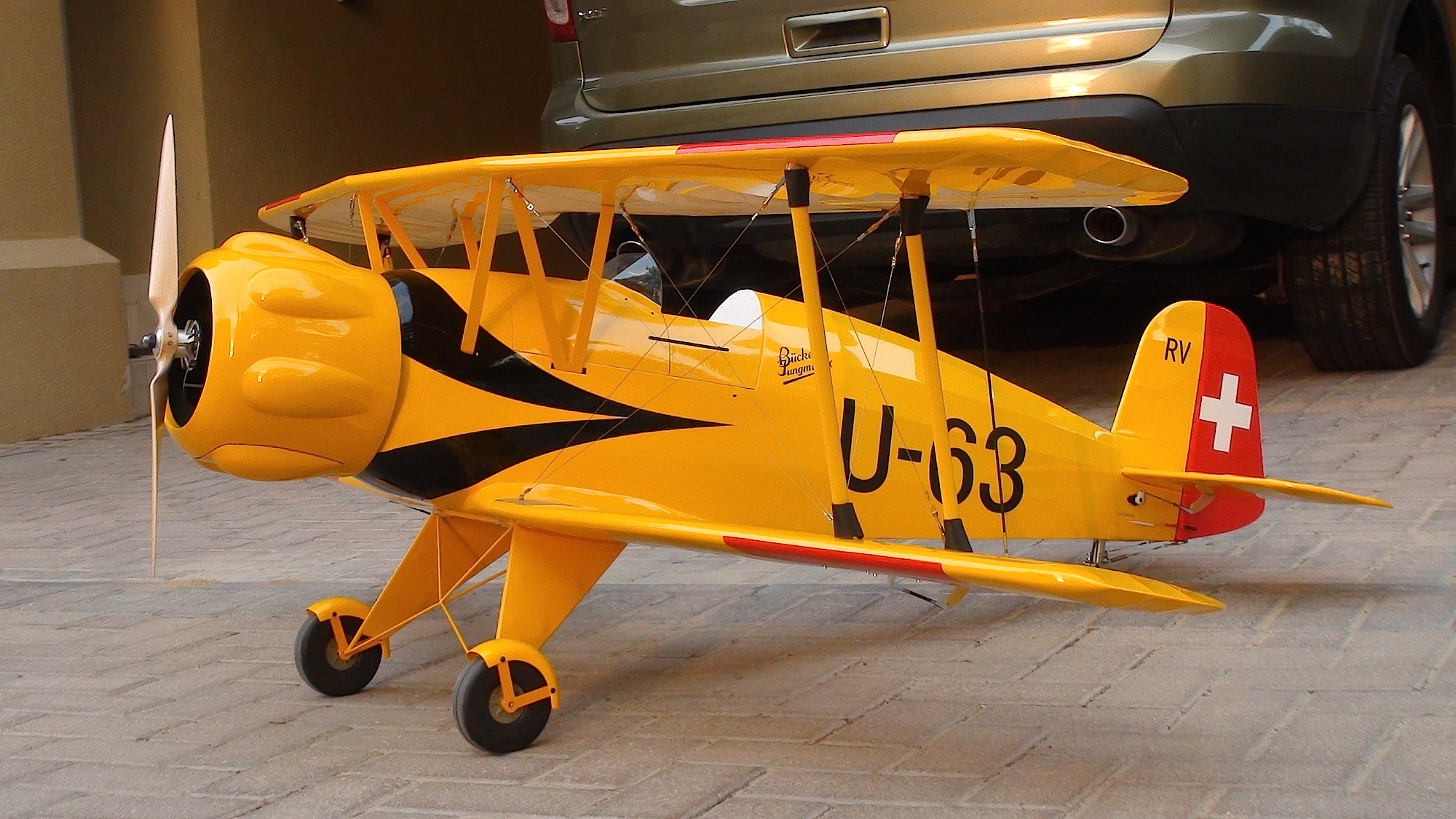
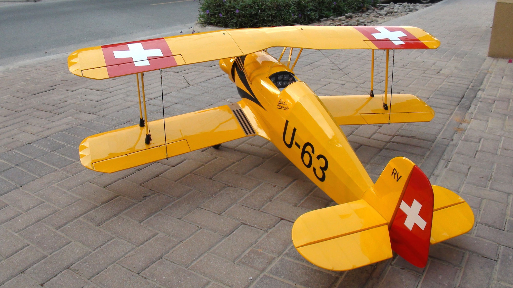
Isn't she beautiful????
Now let's see if she flies the same way.....
The positiv points
- All parts fit together nicely without any adjustments
- Covering in real Oracover, perfectly applied
- Accessories are of good quality
- Composite ruder horns, slots already milled out
- Generally robust yet light construction
The negativ points
- The design of the "Swiss" version is far from what it should be. What were they thinking with the black stripe on the cowl and the swiss cross only on 1 side!???
- The engine cowl is way to big. I do understand their point to accommodate a variety of engines though.
- The wing braces could be done better. They are way to fat, and in my case there was 4 equal pieces instead of 2 left & 2 right!
- The wheels are useless and will get to you! (it did on my maiden! But later about that
). They are wobbly and WILL touch the fenders!- The mounting of the engine cowling might not sustain for long if done the way its meant to, specially if you install a nitro or gas engine.
- Some parts are unfortunately built way to heavy. The vertical fin and stabiliser could be built much lighter. The landing gear weighs quite a bit too.
- The rod that moves the upper aileron via the lower one is heavy too (steel, 3mm) and has way too much play.
- The ailerons on my model were twisted. One had a positiv wash out, the other one a negativ. I bent them a bit, but the rest had to be done taking the ailerons out of center.
- The wheels were not properly aligned and the wire had to be bent a little to get them pointing inwards a bit.
Enough talking...now for some pictures!
Isn't she beautiful????
Now let's see if she flies the same way.....
12-31-2014, 02:54 AM
#33
Member
Join Date: Oct 2006
Location: Dubai, UNITED ARAB EMIRATES
Posts: 40
Likes: 0
Received 2 Likes
on
2 Posts
With everything measured and properly aligned I had a good feeling and did the maiden yesterday morning.
Well, if I say good feeling...that was apart from the wheels which were a bit of a concern to me.
But anyway, let's fly that thing.
My adjustments proved to be right. The model accelerated straight down the runway, lifted soon its tail and then got airborne, like it has been flying ever since!
I needed 2 clicks of left trim (the twisted ailerons! ), but then it was flying straight and level. Beautiful!
The CG seemed to be alright so I went inverted. Needed some pushing...so perfect.
The chosen thrust angle proved to be too much. The plane pulled to the right.
After the flight I also noticed a slight deflection to the right...hmmm...must have missed that!?
So how does it fly???
It flies beautifully. Very solid and stable. Gives the impression to fly something much bigger.
You can see how stable it flies in the video!
The improved Swiss design looks fantastic in the air!
The weight is ideal, it feels very light.
So far so good.
Turning downwind for a landing. I did it wide and low in order to feel how much thrust I needed to "pull" her in onto the runway.
Well, it turns out...A LOT.
The drag on that thing is massive, considering the low weight as well.
I was too slow to advance the throttle and that thing hit the runway quite hard.
The wheels then kicked in and slowed the model down so much on impact that it was not really flying anymore but still got airborne again.
On the second touch the wheels again, touching the screws on the fenders, created such a braking action that the B�cker went on the nose.
I think even with a beautiful landing it would have been inevitable not to end up on the nose.
Oh well, a part from some scratches on the cowl everything was alright.
With a little bit of effort this ARF kit can be transformed into a beautifully looking, very well flying model!!
As soon as the wheel issue is resolved I will do some more flying to see how she handles different ae
Martin
http://www.youtube.com/watch?v=Ibqyyp7ziAg
Well, if I say good feeling...that was apart from the wheels which were a bit of a concern to me.
But anyway, let's fly that thing.
My adjustments proved to be right. The model accelerated straight down the runway, lifted soon its tail and then got airborne, like it has been flying ever since!
I needed 2 clicks of left trim (the twisted ailerons!
), but then it was flying straight and level. Beautiful!The CG seemed to be alright so I went inverted. Needed some pushing...so perfect.
The chosen thrust angle proved to be too much. The plane pulled to the right.
After the flight I also noticed a slight deflection to the right...hmmm...must have missed that!?
So how does it fly???
It flies beautifully. Very solid and stable. Gives the impression to fly something much bigger.
You can see how stable it flies in the video!
The improved Swiss design looks fantastic in the air!
The weight is ideal, it feels very light.
So far so good.
Turning downwind for a landing. I did it wide and low in order to feel how much thrust I needed to "pull" her in onto the runway.
Well, it turns out...A LOT.
The drag on that thing is massive, considering the low weight as well.
I was too slow to advance the throttle and that thing hit the runway quite hard.
The wheels then kicked in and slowed the model down so much on impact that it was not really flying anymore but still got airborne again.
On the second touch the wheels again, touching the screws on the fenders, created such a braking action that the B�cker went on the nose.
I think even with a beautiful landing it would have been inevitable not to end up on the nose.
Oh well, a part from some scratches on the cowl everything was alright.
With a little bit of effort this ARF kit can be transformed into a beautifully looking, very well flying model!!
As soon as the wheel issue is resolved I will do some more flying to see how she handles different ae
Martin
http://www.youtube.com/watch?v=Ibqyyp7ziAg
The following users liked this post:
apereira (03-16-2022)
12-31-2014, 08:17 AM
#35
My Feedback: (4)
Join Date: Sep 2003
Location: Payson,
AZ
Posts: 226
Likes: 0
Received 0 Likes
on
0 Posts
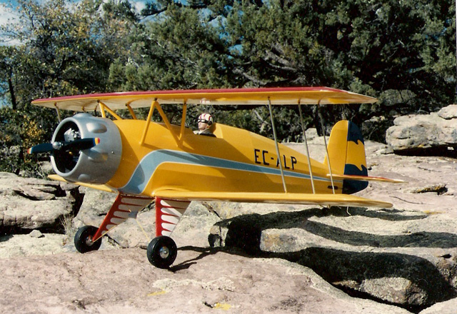
Excellent build Martin. Thank you for leading the way to end up with a great airplane. I will certainly copy most if not all of what you have done. Here's my Dave Platt Jungmeister in Count Aresti's scheme. Red sunburst on top of upper wing. Platt is true scale, a master scale builder. Note the blisters on the cowl are shorter. Maybe the cowl is smaller also.
Dave
Dave
Last edited by av8djc; 12-31-2014 at 08:32 AM.
12-31-2014, 10:09 AM
#36
Member
Join Date: Oct 2006
Location: Dubai, UNITED ARAB EMIRATES
Posts: 40
Likes: 0
Received 2 Likes
on
2 Posts
Thanks Dave!
Nice model!
Yep...this B�cker looks more scale.
Would love to build that one. On the other hand, if I would build another B�cker it would probably be the Benja 1:2.8 or even 1:2!
Happy New Year!
Nice model!
Yep...this B�cker looks more scale.
Would love to build that one. On the other hand, if I would build another B�cker it would probably be the Benja 1:2.8 or even 1:2!
Happy New Year!
 01-01-2015, 04:22 PM
#38
My Feedback: (4)
Join Date: Sep 2003
Location: Payson,
AZ
Posts: 226
Likes: 0
Received 0 Likes
on
0 Posts
Yep, for my Dave Platt 1/4 scale: http://www.fiberglassspecialtiesinc.com/catalog.htm ($39) They are a quality company that has been around a long time. They also have FG wheel fenders. These can be easily made using an over sized wheel for a mold. I have a mold for the cowl and for the PICA 1/5 scale Jungmeister. When I get my Seagull kit I'll compare the cowl to mine.
Martin, see https://www.youtube.com/watch?v=tnB7L-O2VJo also Google comes up with a lot of large scale Jungmeisters. Much larger than the 1/4 scale I'd just as soon get in it to fly it. Here's a picture of my 8/10 scale called a Jungster that I owned back in the early '80's. It was built (not by me) under the experimental category here in the USA. Primarily spruce and aircraft plywood It was 15 feet square weighed 550 lbs empty. Powered by a 150 HP Lycoming that had no starter to save weight so it had to be hand propped. It had full inverted systems and was a great aerobatic machine. Far nicer than a Pitts or Eagle.
Dave
01-02-2015, 05:09 AM
#39
My Feedback: (4)
Join Date: Sep 2003
Location: Payson,
AZ
Posts: 226
Likes: 0
Received 0 Likes
on
0 Posts
There is an older lengthy build thread of a 58" Jungmeister at http://www.rcgroups.com/forums/showthread.php?t=1311713 and within that the following link to the Bevo Howard airplane : http://www.bevhoward.com/Buecker.htm It's a lengthy thread but full of useful information.
01-13-2015, 09:18 AM
#40
Junior Member
Join Date: Jan 2015
Posts: 2
Likes: 0
Received 0 Likes
on
0 Posts
Martin, I have been reading your build posts with interest. I have not owned a Bi-plane model previously and I am on the brink of purchasing this model.
The mods you have made certainly improve the scale appearance, particularly the inter-plane struts. In fact looking back at the manufacturers photos it is hard to believe they supply those huge box section monstrosities !! I too would have to source some stream lined tube, just as you did, and fabricate new items.
The question I have for you concerns the flying wires. Are these actually required for structural purposes or are they just for scale appearance ? I ask because without doubt the scale arrangement for the wires you have chosen, is a definite improvement in terms of aesthetics. However, is there a risk of structural break up in flight, due to this new arrangement ?
(Please forgive me if the answer to my question is obvious to the more knowledgeable builder).
Regards, Dave
01-13-2015, 09:43 AM
#41
Member
Join Date: Oct 2006
Location: Dubai, UNITED ARAB EMIRATES
Posts: 40
Likes: 0
Received 2 Likes
on
2 Posts
Hi Dave
First of all I do not think the wires are absolutely necessary since the wing tubes go quite far into the wings.
Whats more, the wing struts hold the wings together nicely and form a unit!
The question about my arrangement, well, why do you think they did it that way on the original?
The wires, the way they are planed in the manual are parallel. That means they will not prevent the wing from moving back
and forward.
With my arrangement this is certainly given. In my opinion, my arrangement, if anything, does add to the strength of the plane!
Some people might now say hell yes that is true, while others might be sceptic and say, I think I will do it as planned, the sure will know
why they did it that way.
I think you will have to decide for yourself what makes more sense.
Maybe somebody else, with more knowledge, would like to give his/her opinion!?
One thing is for sure: The model will certainly not fall apart because of any arrangement of the wires!
Cheers, Martin
01-13-2015, 11:58 AM
#42
Junior Member
Join Date: Jan 2015
Posts: 2
Likes: 0
Received 0 Likes
on
0 Posts
Wow, thank you Martin for your quick response !!
I am relatively new to aero modelling (only 2yrs in !! 4 yrs of model heli flying and 27 odd years of full size flying, 15 + on the Pitts S1S ).
).
Thus I totally understand your comment "why did they do that on the original" !!
I asked the question, which you have answered admirably, because i wasn't sure if the wings on the model and their respective wing tubes could take all the flying loads alone. And then if they couldn't, i wondered whether the Vietnamese had attached the wires separately because if they doubled up on a single point (as per the original design) the flying loads would rip the attachment out of the wing !! ... I guess I probably over think these things !! Lol !!
I shall buy one and honour you by rigging the wires as per your build and call it the Martair mod
Regards, Dave
I am relatively new to aero modelling (only 2yrs in !! 4 yrs of model heli flying and 27 odd years of full size flying, 15 + on the Pitts S1S
).Thus I totally understand your comment "why did they do that on the original" !!
I asked the question, which you have answered admirably, because i wasn't sure if the wings on the model and their respective wing tubes could take all the flying loads alone. And then if they couldn't, i wondered whether the Vietnamese had attached the wires separately because if they doubled up on a single point (as per the original design) the flying loads would rip the attachment out of the wing !! ... I guess I probably over think these things !! Lol !!
I shall buy one and honour you by rigging the wires as per your build and call it the Martair mod
Regards, Dave
01-17-2015, 08:16 AM
#43
Join Date: Feb 2013
Location: Monroe, Wisconsin
Posts: 21
Likes: 0
Received 0 Likes
on
0 Posts
Here is the product page for the new Seagull Bucker Jungmeister JU-133 ARF with the Bevo Howard color scheme:
http://www.sigplanes.com/Seagull-Buc...-US_p_272.html
SIGPlanes.com will be accepting pre-orders on this model very shortly.
http://www.sigplanes.com/Seagull-Buc...-US_p_272.html
SIGPlanes.com will be accepting pre-orders on this model very shortly.
02-12-2015, 12:11 PM
#44

OK Jungmeister fans, I've got some eye candy for you. I just finished putting together the first-in-the-U.S. sample of the Seagull Bucker Jungmeiser in the Bevo Howard color scheme. This is the sample Seagull sent here to SIG for us to get ready to show at Toledo (only 6 weeks away). I've enjoyed putting this together, and I've enjoyed even more stepping back every once and a while and just admiring it. She's a beauty. Can you tell I LOVE my Jungmeister. Can hardly wait for spring to get it in the air.
I powered this one with a Power 160 size electric motor (6364-245 to be exact). I've used this motor before in a SIG Rascal 110 and found it to be a good motor for this size airplane; hardly straining with a 8 cell 5000mah lipo pack; Castle Ice 80HV esc; Falcon 18 x 10 wood prop (not the E, but the regular style). I expect it to be a dynamite combination.
I powered this one with a Power 160 size electric motor (6364-245 to be exact). I've used this motor before in a SIG Rascal 110 and found it to be a good motor for this size airplane; hardly straining with a 8 cell 5000mah lipo pack; Castle Ice 80HV esc; Falcon 18 x 10 wood prop (not the E, but the regular style). I expect it to be a dynamite combination.
Last edited by Mike Gretz; 02-21-2015 at 05:47 AM.
02-12-2015, 12:35 PM
#45
More pics with tips on some of the things I ran in to ...
Pic 1:
I had to cut a notch in the nylon bearing that holds the tailwheel. After getting it all installed and turning on the radio, I found that it would not turn left. The RC Link and pushrod were hitting the side of the nylon bearing. Taking the bearing back out I found that the plywood former the bearing mounts to is already notched for the this issue. So Seagull had it figured out, but evidently they didn't want to take time to notch the nylon bearing. Was pretty easy for me to do since I have a bandsaw. Notching it by hand with an x-acto saw and knife would be a bit more time consuming.
Pic 2:
Although the instructions didn't say anything about it, I thought it best to inset the little aluminum strut fittings that they provide into the soft balsa side of the strut, so it would be seated on the plywood inside the strut. Not a hard job with a sharp #11 knife.
Pic 3:
For whatever reason, I decided to paint the inside walls of the cockpit gray, instead of black as it came. One coat of SIG gray butyrate dope took care of that. Any paint should work as well. Don't have the pilot installed yet. The wife is repainting his green helmet and green shirt to brown and white respectively. Just couldn't imagine Bevo Howard in a green shirt. Besides it clashed with all the beautiful red and white. I will be asking Seagull to do the same in the next order of Buckers.
FWIW, I cut the Ultracoat away where the windshield sits and then glued it in place with common white "canopy glue". Then just to be safe I installed 4 small pins in the corners, with a tiny tab of epoxy glue on each pin on the inside.
Pic 4:
Another sorta-scale addition I made on my own was to add a flying wire brace on each side. You know, the piece of wood that connects the front and rear wing flying wires on a full-scale biplane together, just to cut down on the amount of vibrating they will do in flight. I used a length of 1/8" dia. birch dowel, tied in place with white thread. Looks pretty cool, if you ask me.
I LOVE MY BUCKER!
Oh, by the way, the first shipment of the Bevo Howard Jungmeisters will arrive about April 1st. If you want one, SIG and SIGPlanes are taking pre-orders now. The first shipment is limited due to limited container space. There will be more about a month later.
Last edited by Mike Gretz; 02-12-2015 at 05:08 PM.
02-12-2015, 12:54 PM
#46
One more thing.
Like Martin, I found that the bolts provided for mounting the wheel fenders were too long, almost touching the wheels. With any side force at all, like on take off or landing, the bolts were going to dig into the wheels. So I cut them off with a dremel abrasive cutoff wheel.
Holding onto such small bolts while cutting them off is not something you want to do by hand, or with a pliers. And clamping the bolt in a vise is not secure enough either. Nothing worse than having the tiny bolt go flying across the shop, never to be seen again.
Here's a technique for cutting off bolts that I learned from a gunsmith friend of mine.
!) Screw the bolt into the proper hole of a common "screw checker". If you don't have screw checkers in both US and metric, you ought to get them. They only cost a few bucks. Any tool shop will have them, or there is always ebay or amazon.
Screw the bolt into the screw checker from the top. Tighten a hex nut against the top surface of the screw checker to secure the bolt in place. The distance from the head of the bolt to the bottom side of the screw checker is the length you will end up with.
2) Use your dremel cut-off wheel to cut off most of the excess bolt sticking out the backside of the screw checker. Don't try to cut it off flush with the checker. Just close for now.
3) Take it to your bench grinder and carefully grind the remaining excess bolt perfectly flush with the backside of the screw checker.
There you go. The bolt is now the right length, the end is nice and smooth without burrs, and best of all ... the bolt is not lost on the floor of the shop.
Last edited by Mike Gretz; 02-13-2015 at 09:59 AM.
