


Scratch Built Semi-Scale Sandrail
 09-10-2009, 11:07 PM
#1
Senior Member
Thread Starter
My Feedback: (6)
Join Date: Jan 2004
Location: Los Altos Hills, CA
Posts: 491
Likes: 0
Received 0 Likes
on
0 Posts
So I posted this in another forum but it sounds like some of you guys miss my projects so here it goes. this was my big to-do at the beginning of the year.
It all started with an engine……
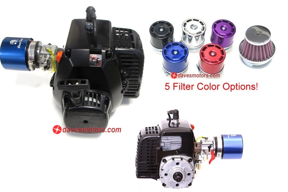
Mark from TGN approached me and asked me if there was anyway to shoe-horn this motor into a baja. Without really thinking about it I of course told him sure! Right off the bat I decided that this was too much motor for the baja gear-box and drive train. So I set out to not only figure a way to drop this motor into a baja but also design a transmission around the motor.
On a side note, for the longest time I wanted to do a true tube frame sandrail chassis for this car. Something scale and true to the nature of a sandrail. I wanted something that would basically consist of a tubular frame with weld tabs for all the suspension points and misc. hardware. This is where I decided to merge the two ideas in to what would be the ultimate sandrail RC build. As scale as possible without actually having a sandrail in front of me to pull dimensions from.
This full size sandrail is what I used for inspiration....
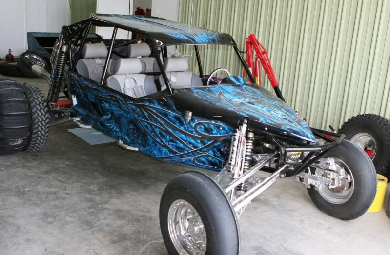
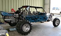
This sandrail was on display at RCX 2009 in the TGN booth.
I began by modeling the engine, capturing only the features that would be critical in the design of the transmission.
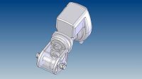
This was my initial design but I ended up going in a different direction
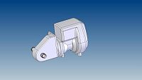
This is the finished model from which I would make the transmission parts from

From this view you can see the internals.
For the transmission design I wanted to use mostly what I had on hand. I had a large diff that I would pull the bevel gears from, I used a couple of gears from the HPI baja, and picked up a couple of gears from McMaster. To keep things simple and reliable I designed the transmission with a locked output drive instead of a differential. I figured since this was only for sand that this would be fine.
It all started with an engine……
Mark from TGN approached me and asked me if there was anyway to shoe-horn this motor into a baja. Without really thinking about it I of course told him sure! Right off the bat I decided that this was too much motor for the baja gear-box and drive train. So I set out to not only figure a way to drop this motor into a baja but also design a transmission around the motor.
On a side note, for the longest time I wanted to do a true tube frame sandrail chassis for this car. Something scale and true to the nature of a sandrail. I wanted something that would basically consist of a tubular frame with weld tabs for all the suspension points and misc. hardware. This is where I decided to merge the two ideas in to what would be the ultimate sandrail RC build. As scale as possible without actually having a sandrail in front of me to pull dimensions from.
This full size sandrail is what I used for inspiration....
This sandrail was on display at RCX 2009 in the TGN booth.
I began by modeling the engine, capturing only the features that would be critical in the design of the transmission.
This was my initial design but I ended up going in a different direction
This is the finished model from which I would make the transmission parts from
From this view you can see the internals.
For the transmission design I wanted to use mostly what I had on hand. I had a large diff that I would pull the bevel gears from, I used a couple of gears from the HPI baja, and picked up a couple of gears from McMaster. To keep things simple and reliable I designed the transmission with a locked output drive instead of a differential. I figured since this was only for sand that this would be fine.
 09-10-2009, 11:09 PM
#2
Senior Member
Thread Starter
My Feedback: (6)
Join Date: Jan 2004
Location: Los Altos Hills, CA
Posts: 491
Likes: 0
Received 0 Likes
on
0 Posts
I started by modifying the clutch bell carrier. This would bolt directly to the transmission (from now on I guess I will more appropriately refer to it as a gear-box).
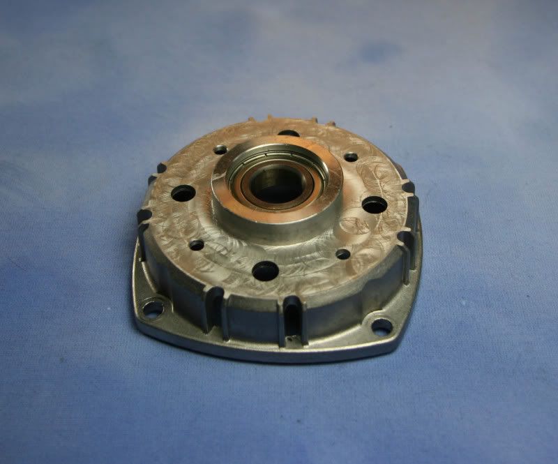
This is the modified clutch bell carrier. In addition to being machined flat I also machined a reference datum for the input gear and a bolt hole pattern to mount to the gear-box.
Next I machined the rear cover plate for the gear-box. This is what would bolt directly to the clutch bell carrier.
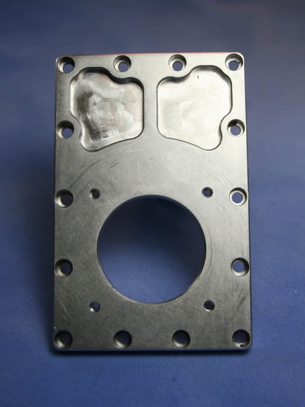
Finished rear cover plate.
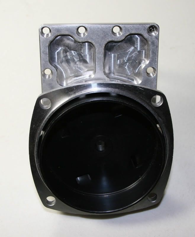
Here you can see the clutch bell carrier mounted to the rear cover plate
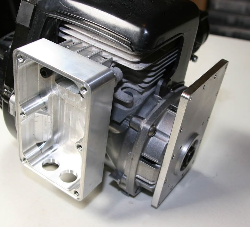
Here the plate and clutch bell carrier are installed onto the engine.
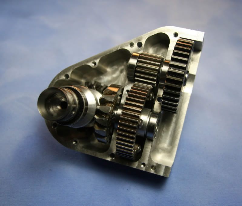
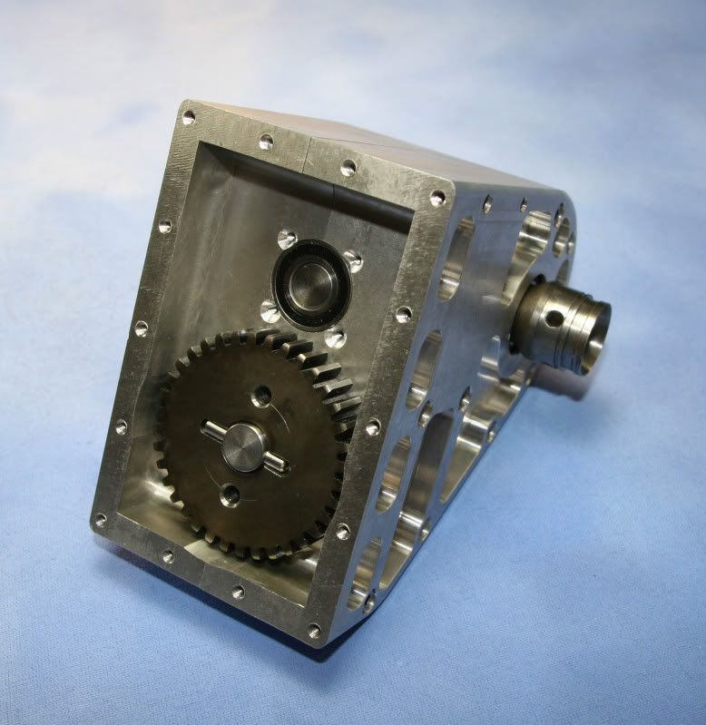
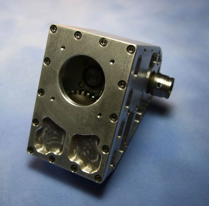
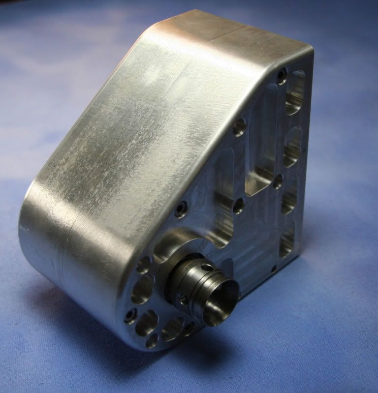
Next up was the gear-box case halves. This was a first for me on my CNC as far as part complexity, # of operations and set-ups. I also had over-sized billet stock so It took forever to hog out the part. The two halves locate to each other with dowel pins and the they are held together from both sides with a pattern of M4 screws as well as the rear cover plate.
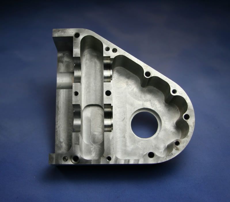
Here is one halve. Notice the details
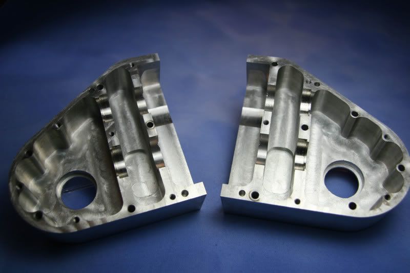
Here are the two matching halves side-by-side.
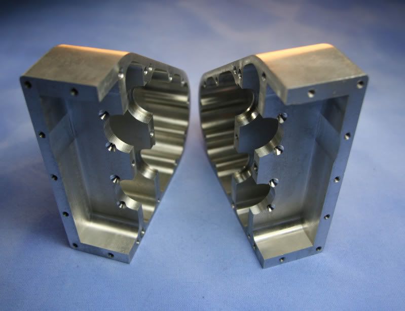
.....and again.
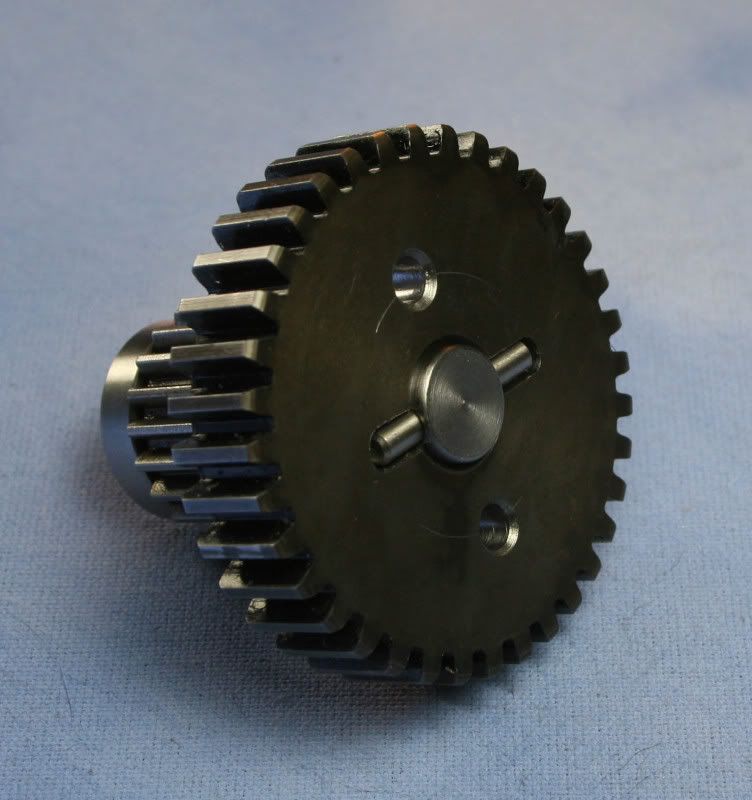
Now onto the individual gear components. I started with some bevel gears from a large gear differential. The differential was pulled from one of those motorized shopping cart fetchers. Don't ask me where I got it. I modified the two matching gears by machining dowel pin slots into the faces of each gear. This way I could key the gear onto the drive shafts.
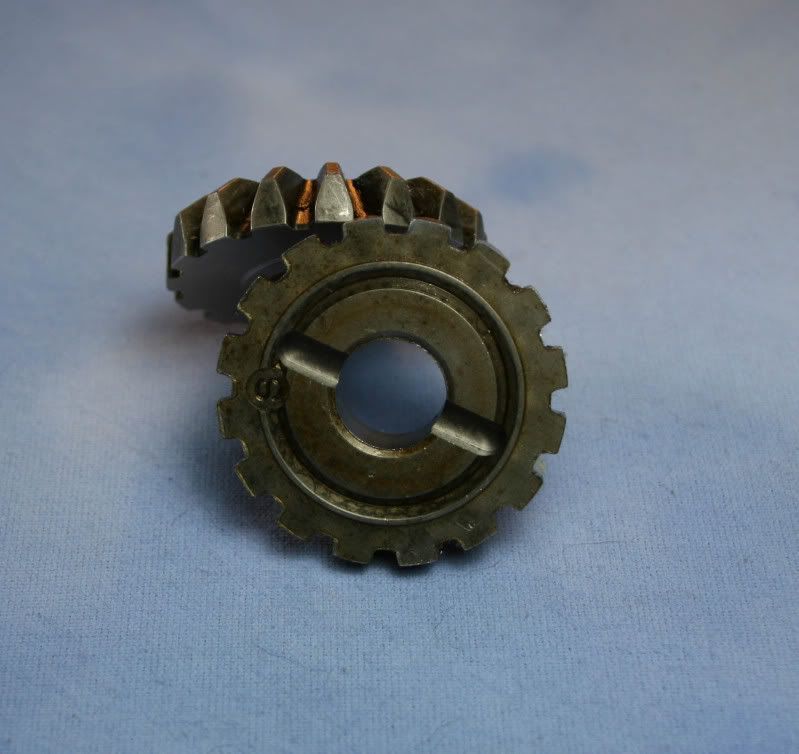
Gear 1 modified with a dowel pin slot
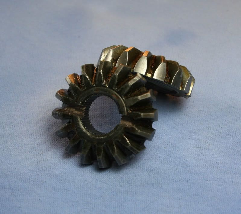
Gear 2 modified with a dowel pin slot
The clutch bell is different that that of a baja. Instead of a boss with a tapped hole it just has a large tapped hole in the center of the shaft. This is designed to have a pinion sprocket thread into the hole until it is snug up against a datum face. I had to machine a custom steal gear to work with this clutch bell.
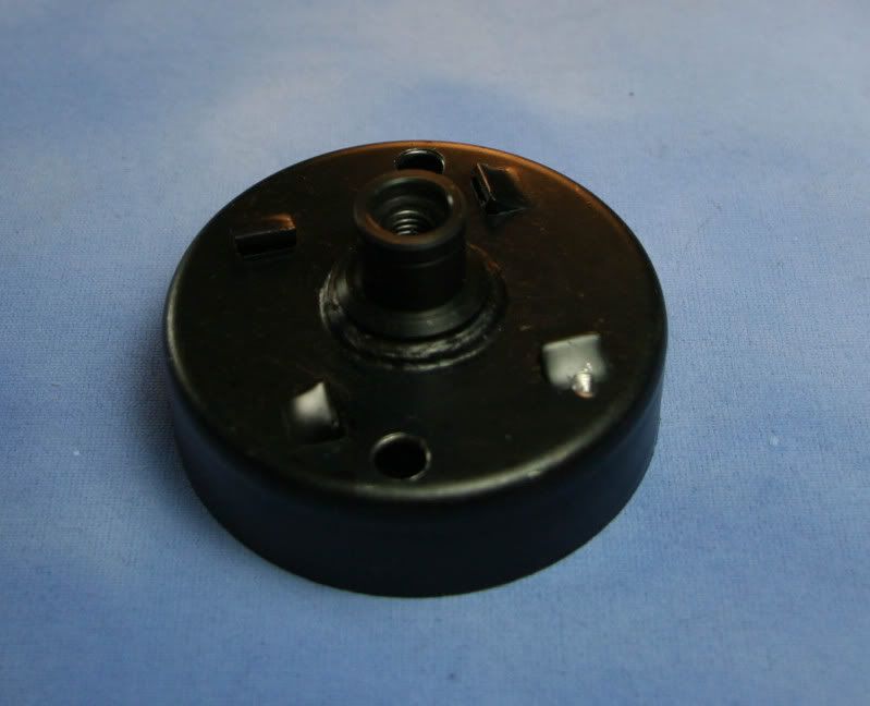
This is the clutch bell.
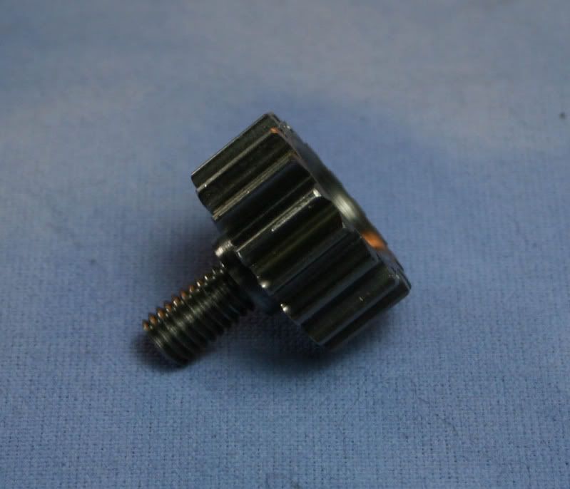
This is the custom pinion that I machined.
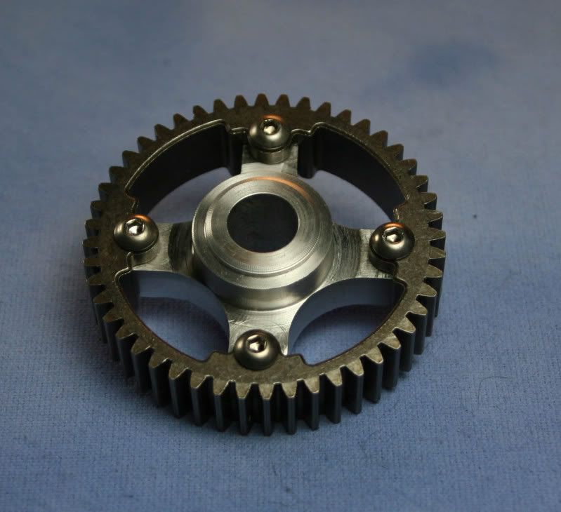
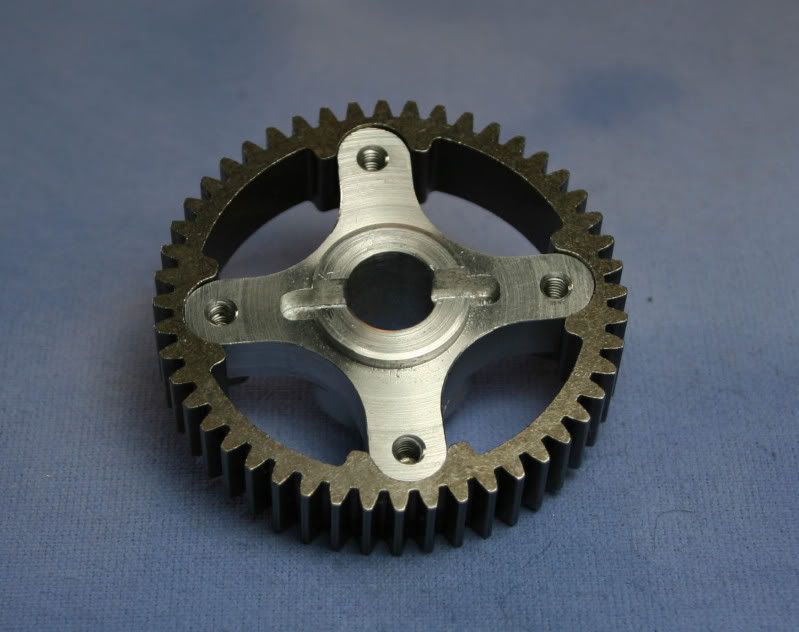
Next up was to modify the input spur gear. I bought a gear from McMaster and modified it. I first machined a dowel pin slot into one face so that I could key it to the drive shaft. Then I drilled some access holes in the face. These holes are for the bearing retaining screws that are hidden behind the gear. Then I machined the other side of the gear to remove material and make it as light as possible.
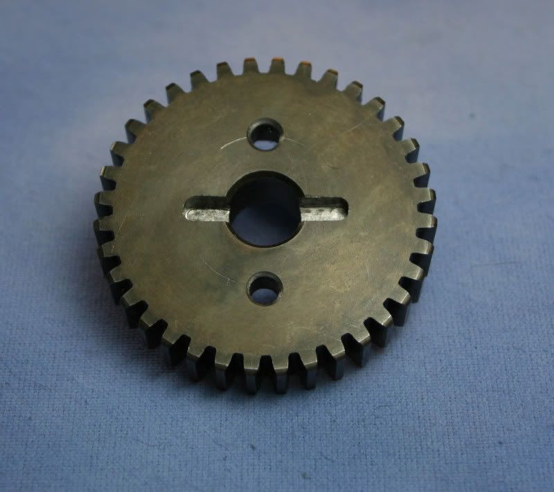
Here is the gear with the dowel pin slot and access holes.
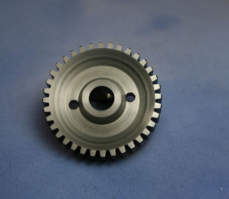
And here is the other side of the gear with material removed.
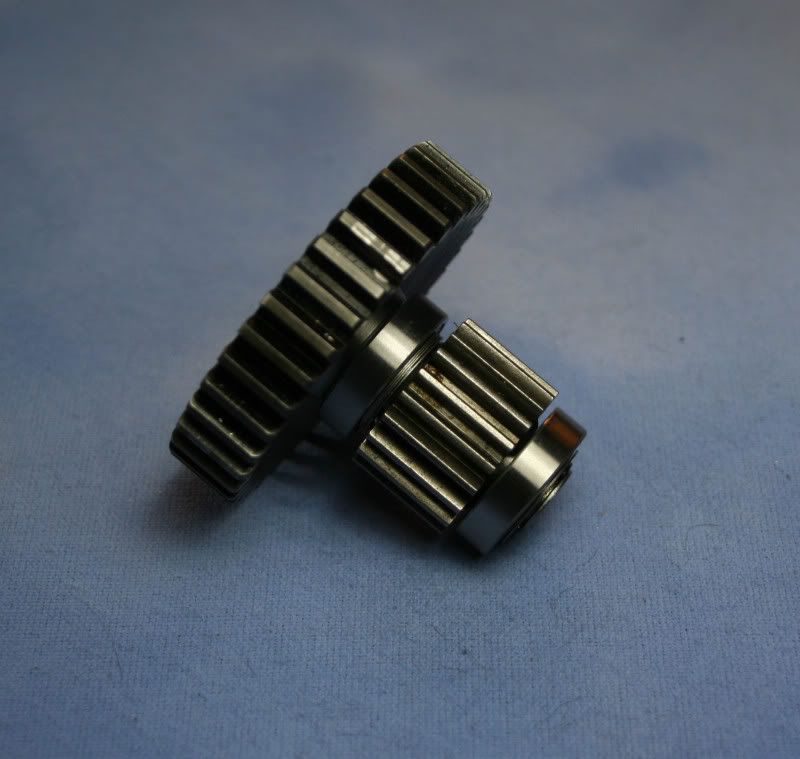
The other two gears used in the gear-box were the diff gear and the layshaft pinion gear from the HPI Baja. These did not require an modifications. Next on the to-do list were a couple of drive shafts and hub for the HPI diff gear. I started with the hub. I designed it and ran the first opp through the CNC then moved it to my lathe for secondary operations. The two drive shafts were machined to transfer power between all the gears. These were designed and machined to hold the dowel pins that would key the gears to the shafts.
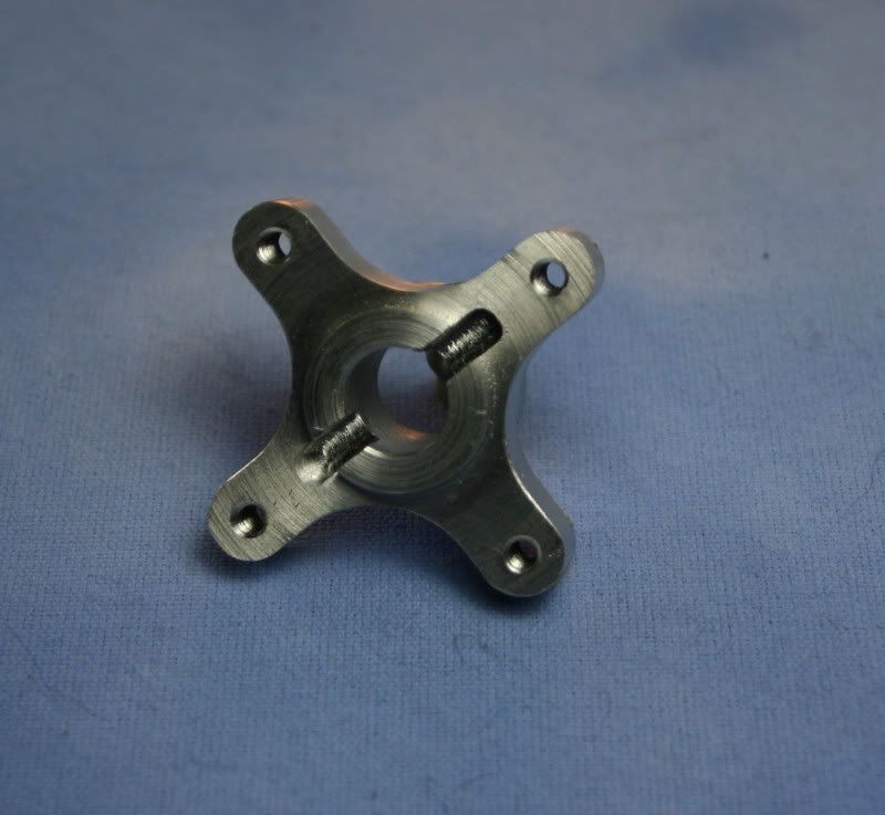
Here is the diff gear hub. One side has a slot for a dowel pin to key it to the drive shaft.
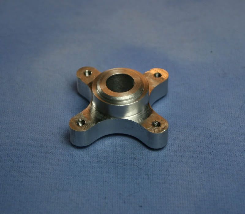
This is the other side of the gear hub.
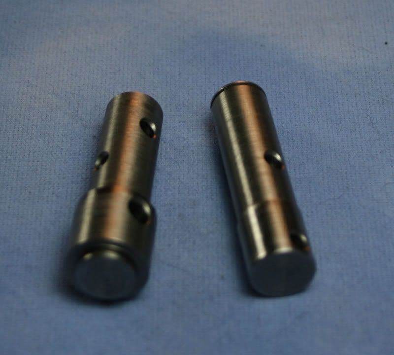
These are the two machined drive shafts.
Now onto the gear-box output shaft/spool. The spool was machined from 6061-T6 Aluminum. For this sandrail build I wanted the drive shafts to be scale. To do this I designed the drive shafts to have CV joints on both ends with a telescoping mid section. I modified a couple of my CV-Bone cups so that they could be keyed to the spool piece with dowel pins.
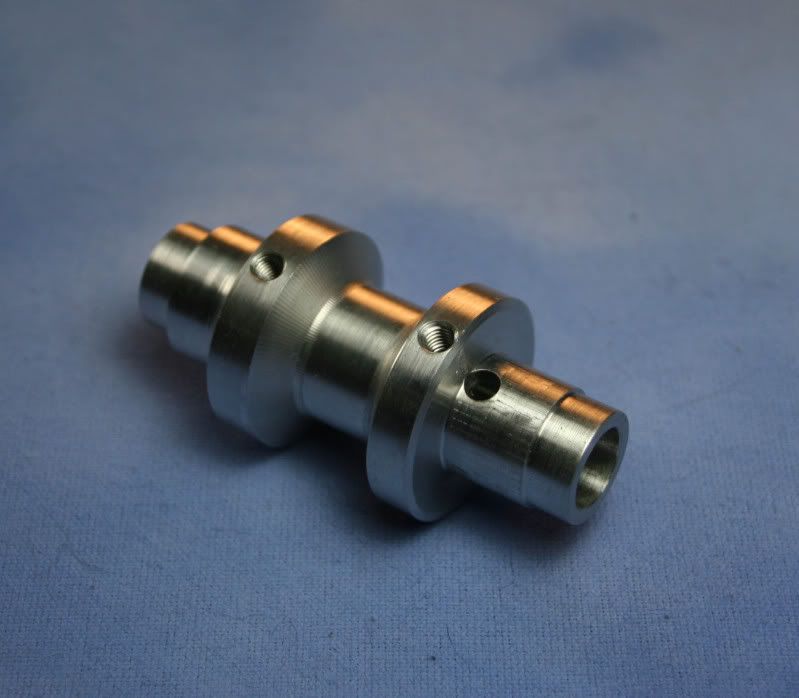
Here is the machined spool.
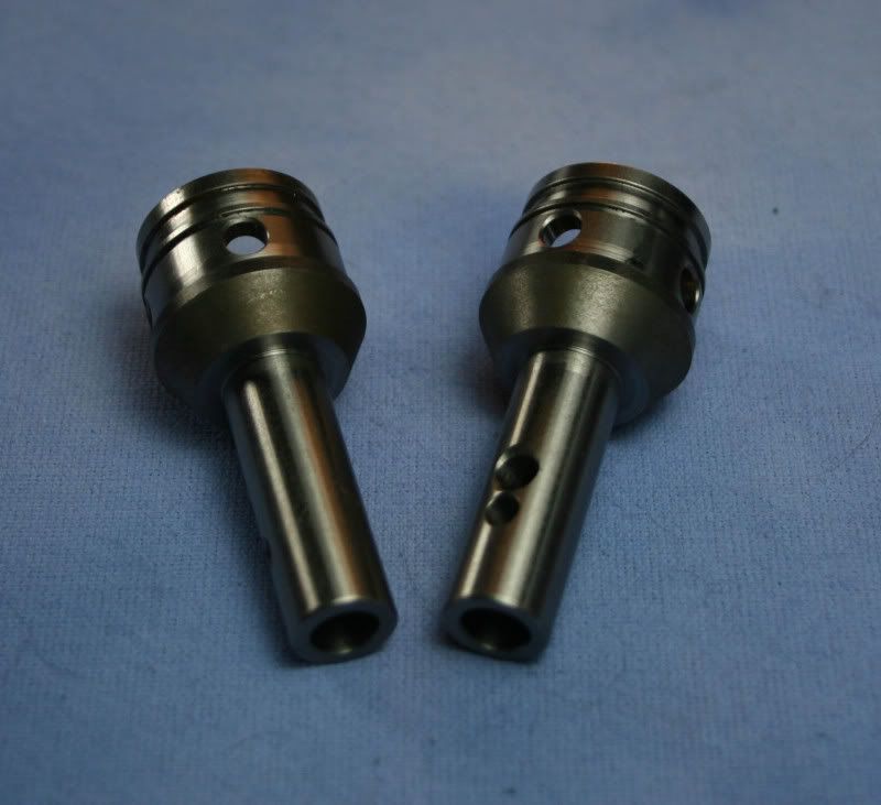
Here are the modified drive cups.
With that I have finished machining all the components for the gear-box. Stay tuned for the gear box assembly. . .
This is the modified clutch bell carrier. In addition to being machined flat I also machined a reference datum for the input gear and a bolt hole pattern to mount to the gear-box.
Next I machined the rear cover plate for the gear-box. This is what would bolt directly to the clutch bell carrier.
Finished rear cover plate.
Here you can see the clutch bell carrier mounted to the rear cover plate
Here the plate and clutch bell carrier are installed onto the engine.
Next up was the gear-box case halves. This was a first for me on my CNC as far as part complexity, # of operations and set-ups. I also had over-sized billet stock so It took forever to hog out the part. The two halves locate to each other with dowel pins and the they are held together from both sides with a pattern of M4 screws as well as the rear cover plate.
Here is one halve. Notice the details
Here are the two matching halves side-by-side.
.....and again.
Now onto the individual gear components. I started with some bevel gears from a large gear differential. The differential was pulled from one of those motorized shopping cart fetchers. Don't ask me where I got it. I modified the two matching gears by machining dowel pin slots into the faces of each gear. This way I could key the gear onto the drive shafts.
Gear 1 modified with a dowel pin slot
Gear 2 modified with a dowel pin slot
The clutch bell is different that that of a baja. Instead of a boss with a tapped hole it just has a large tapped hole in the center of the shaft. This is designed to have a pinion sprocket thread into the hole until it is snug up against a datum face. I had to machine a custom steal gear to work with this clutch bell.
This is the clutch bell.
This is the custom pinion that I machined.
Next up was to modify the input spur gear. I bought a gear from McMaster and modified it. I first machined a dowel pin slot into one face so that I could key it to the drive shaft. Then I drilled some access holes in the face. These holes are for the bearing retaining screws that are hidden behind the gear. Then I machined the other side of the gear to remove material and make it as light as possible.
Here is the gear with the dowel pin slot and access holes.
And here is the other side of the gear with material removed.
The other two gears used in the gear-box were the diff gear and the layshaft pinion gear from the HPI Baja. These did not require an modifications. Next on the to-do list were a couple of drive shafts and hub for the HPI diff gear. I started with the hub. I designed it and ran the first opp through the CNC then moved it to my lathe for secondary operations. The two drive shafts were machined to transfer power between all the gears. These were designed and machined to hold the dowel pins that would key the gears to the shafts.
Here is the diff gear hub. One side has a slot for a dowel pin to key it to the drive shaft.
This is the other side of the gear hub.
These are the two machined drive shafts.
Now onto the gear-box output shaft/spool. The spool was machined from 6061-T6 Aluminum. For this sandrail build I wanted the drive shafts to be scale. To do this I designed the drive shafts to have CV joints on both ends with a telescoping mid section. I modified a couple of my CV-Bone cups so that they could be keyed to the spool piece with dowel pins.
Here is the machined spool.
Here are the modified drive cups.
With that I have finished machining all the components for the gear-box. Stay tuned for the gear box assembly. . .
09-10-2009, 11:10 PM
#3
Senior Member
Thread Starter
My Feedback: (6)
Join Date: Jan 2004
Location: Los Altos Hills, CA
Posts: 491
Likes: 0
Received 0 Likes
on
0 Posts
Assembling the gear-box is tricky at best it's like a puzzle and there is a very specific order to the assembly otherwise it would be impossible. As tricky as it is to assemble it it was even more difficult to design this so that it would in fact be possible.
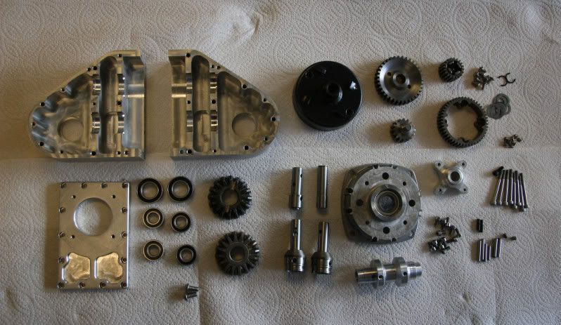
As you can see from the parts layout there are quit a bit of parts for this gear-box.
The first step was the diff gear to the hub. This was the easiest. Then I would install the diff gear on the one of the drive shafts. All the gears are keyed onto the shafts with dowel pins and held in place with clips or shoulder features machine on the drive shaft. The diff gear transfers power to one of the bevel gears.
This is the diff gear installed to the gear hub. Notice the nice tight fit between the two parts. You almost don't need screws to hold them together.
This is the other side of the assembly.
Here the diff gear is installed onto the drive shaft with the bevel gear and a couple of support bearings.
Here is the opposite side of the assembly. The bevel gear is held in place with a clip.
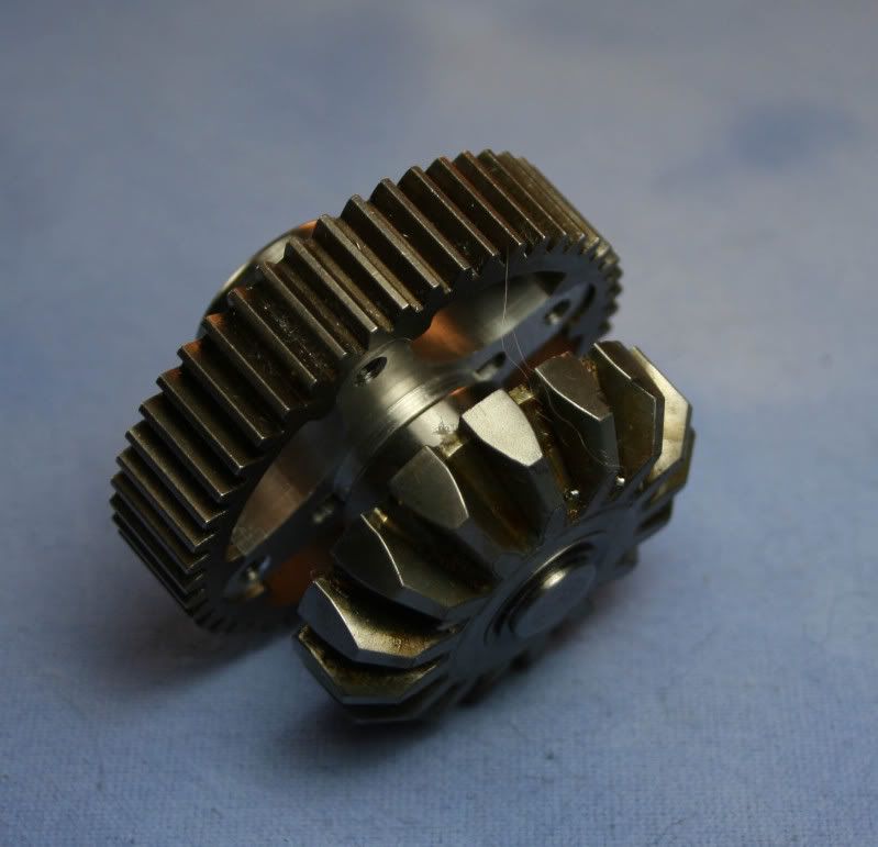
Next I assembled the input spur drive shaft. This drive shaft has the input spur gear which transfers power to an reduction gear which transfers power to the diff gear from the previous assembly.
Here you can see the input spur gear keyed to the shaft with a dowel pin. The dowel pin also locks the gear to the shaft
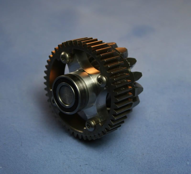
Here you can clearly see the whole assembly with the reduction gear and the support bearings. The whole assembly is held together with a clip. Very simple and elegant in design, but a nightmare to try and figure out.
The next assembly on the list is the spool with the outdrive cups. This was also a tricky little assembly. The entire assembly consists of the spool piece, two outdrive cups, two large bearings, a bevel gear, and some misc. hardware. On the left side, a bearing is first installed, then a drive cup. The cup is keyed to the spool with a dowel pin. The dowel pin is held in place with two grub screws one from each side of the pin. The right hand side of the assembly was a little more tricky. First the gear is installed then the support bearing, then the drive cup. Both the drive cup and the bevel gear are keyed to the spool with a single dowel pin. The dowel pin is held in place with a grub screw inside the shaft of the drive cup. The only way to get to this grub screw is with a long drive inserted from the left hand side all the way through the assembly.
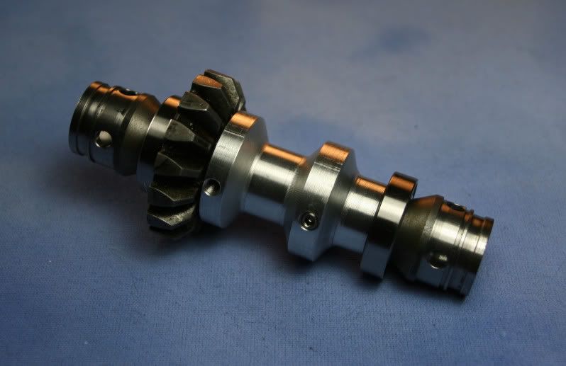
Here is the completed assembly.
Now it's time to install all the sub-assemblies into the gear-box case. First I installed the spool assembly. Then the two drive shaft assemblies. Next, two case halves were bolted together. With the two halves together I then installed the retaining screws that would hold the two exposed support bearing in place. Lastly the rear cover plate gets installed.
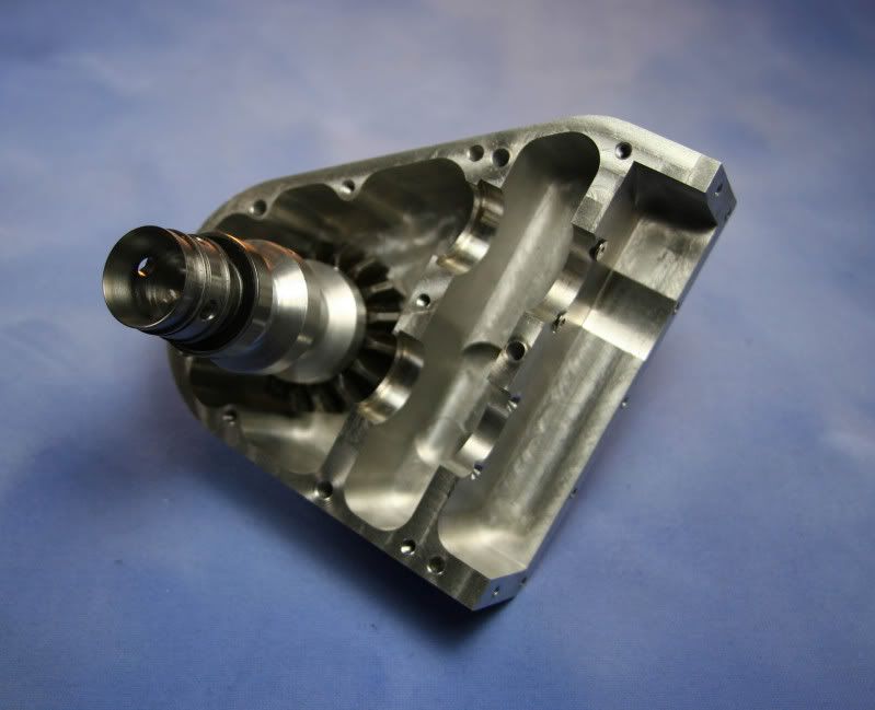
Here the spool piece is installed.
Here the two drive shafts are installed.
Here the two case halves are bolted together. In the photo you can see one of two bearings that is held in place with retaining screws.
Finally the rear cover plate is installed.
The finished gear-box.
Tune in next where I begin the fabrication of the tube frame/chassis. . .
As you can see from the parts layout there are quit a bit of parts for this gear-box.
The first step was the diff gear to the hub. This was the easiest. Then I would install the diff gear on the one of the drive shafts. All the gears are keyed onto the shafts with dowel pins and held in place with clips or shoulder features machine on the drive shaft. The diff gear transfers power to one of the bevel gears.
This is the diff gear installed to the gear hub. Notice the nice tight fit between the two parts. You almost don't need screws to hold them together.
This is the other side of the assembly.
Here the diff gear is installed onto the drive shaft with the bevel gear and a couple of support bearings.
Here is the opposite side of the assembly. The bevel gear is held in place with a clip.
Next I assembled the input spur drive shaft. This drive shaft has the input spur gear which transfers power to an reduction gear which transfers power to the diff gear from the previous assembly.
Here you can see the input spur gear keyed to the shaft with a dowel pin. The dowel pin also locks the gear to the shaft
Here you can clearly see the whole assembly with the reduction gear and the support bearings. The whole assembly is held together with a clip. Very simple and elegant in design, but a nightmare to try and figure out.
The next assembly on the list is the spool with the outdrive cups. This was also a tricky little assembly. The entire assembly consists of the spool piece, two outdrive cups, two large bearings, a bevel gear, and some misc. hardware. On the left side, a bearing is first installed, then a drive cup. The cup is keyed to the spool with a dowel pin. The dowel pin is held in place with two grub screws one from each side of the pin. The right hand side of the assembly was a little more tricky. First the gear is installed then the support bearing, then the drive cup. Both the drive cup and the bevel gear are keyed to the spool with a single dowel pin. The dowel pin is held in place with a grub screw inside the shaft of the drive cup. The only way to get to this grub screw is with a long drive inserted from the left hand side all the way through the assembly.
Here is the completed assembly.
Now it's time to install all the sub-assemblies into the gear-box case. First I installed the spool assembly. Then the two drive shaft assemblies. Next, two case halves were bolted together. With the two halves together I then installed the retaining screws that would hold the two exposed support bearing in place. Lastly the rear cover plate gets installed.
Here the spool piece is installed.
Here the two drive shafts are installed.
Here the two case halves are bolted together. In the photo you can see one of two bearings that is held in place with retaining screws.
Finally the rear cover plate is installed.
The finished gear-box.
Tune in next where I begin the fabrication of the tube frame/chassis. . .
09-10-2009, 11:12 PM
#4
Senior Member
Thread Starter
My Feedback: (6)
Join Date: Jan 2004
Location: Los Altos Hills, CA
Posts: 491
Likes: 0
Received 0 Likes
on
0 Posts
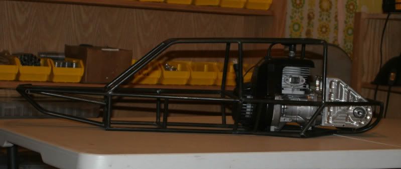
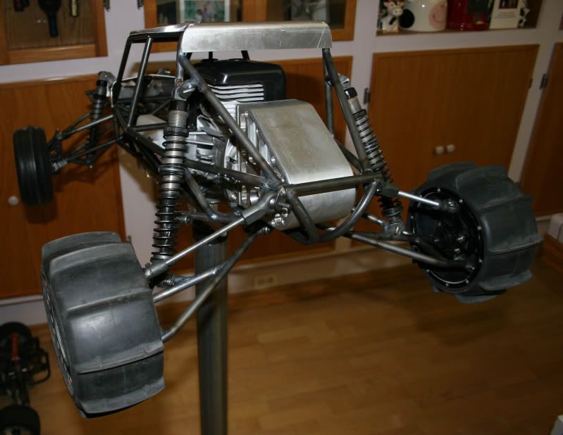
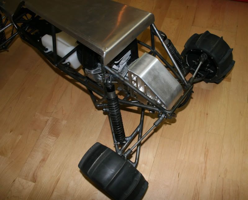
On to the chassis. The chassis for this vehicle was made from 3/8 x .049 wall 4130 chromoly tubing. I picked up a cheap tubing bender from Harbor freight which works very nice for this small tubing. When you purchase a bender you always want to make sure it is specifically for tubing. Most of the crap out there is for pipe and will not work on tubing. The chassis was mocked up and spot welded then I went back and TIG welded all of the joints. There was about two days worth of welding to finish up the chassis. I started the chassis by fabricating up the rear end around the gear-box and engine. Some of these photos were taken with my cell phone so I'm sorry for the quality.
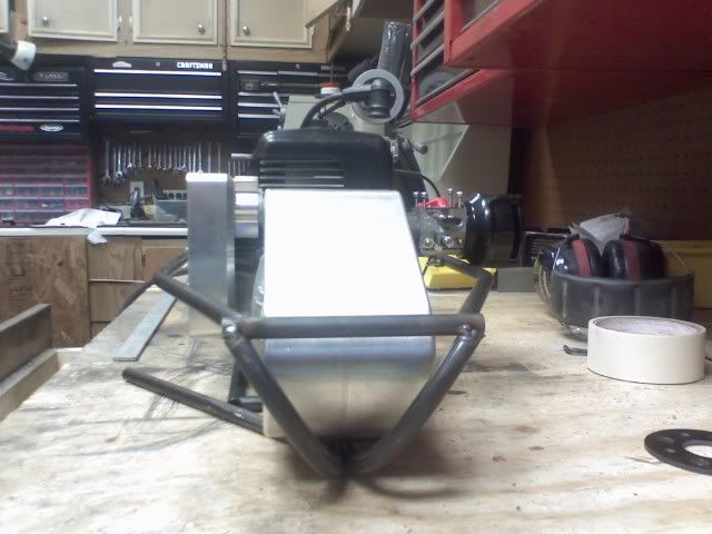
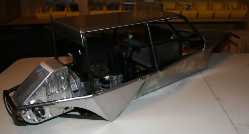
I wanted the chassis to wrap around the gear-box and protect it.
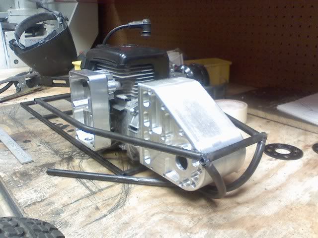
To keep the car scale I used a TGN X-Can for the exhaust. This had to be tucked away inside the chassis on the left-hand side
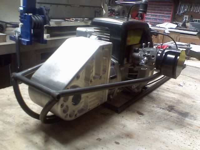
On the right hand side the intake filter sticks out a little bit but in the end that was OK.
I then worked from the rear of the chassis to the front. I kind of had an idea of the total length that I wanted the vehicle to be and I knew what components I wanted to fit into the chassis. I first fabbed up the lower portion of the chassis all the way to the nose then I proceeded onto the cage. There were so many things to consider at this point that it was very difficult to figure out which direction to go. I had to worry about keeping it proportionally scale. I wanted nice clean lines. The geometry had to be structurally sound. This is also where I had to start defining the suspension geometry. For the front I was going to use a typical A-arm set-up. In the rear I wanted to do a pseudo trailing arm. I also had to keep in mind on how I would get the engine and gear-box into and out of the frame.
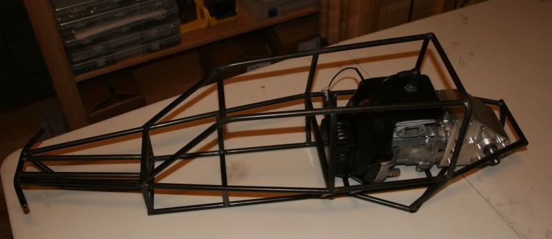
Stage 1 of the frame. From here it should get easier.
A side view of the frame
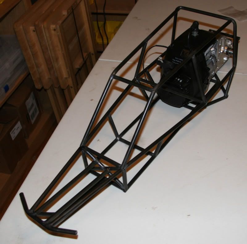
An isometric view of the frame.
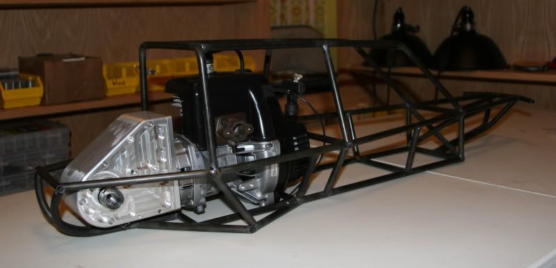
Another isometric view.
Some detail on the front end.
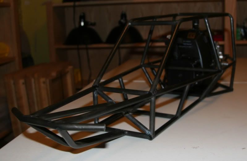
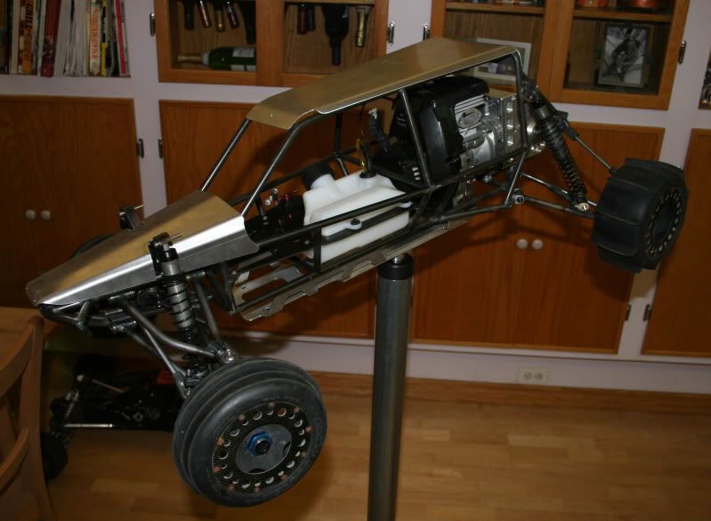
I kind of stopped keeping track of the progress from here but once the frame was done I welded on all of the tabs for the suspensions, motor mounts, gas tank mounts, radio gear etc. . . With the frame welded up I finished it with a nice black powder coat. This is my first time having stuff powder coated and there is nothing more breathtaking than a welded frame that has been powder coated.
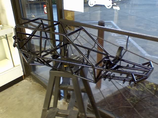
The frame back from the powder coater.
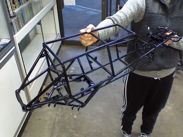
Another shot of the finished frame.
Once the frame was roughed out I started in on the body panels. I can do almost anything with metal but when it comes to sheet metal I am at a loss. I can bend up a box any day of the week but when it comes to complex shapes like body panels I have mad respect for the guy that can do it and do it well. These panels were made from aluminum. There ended up being a total of seven panels. I think I wasted four times more material in screw-ups than what was actually used for the final panels.
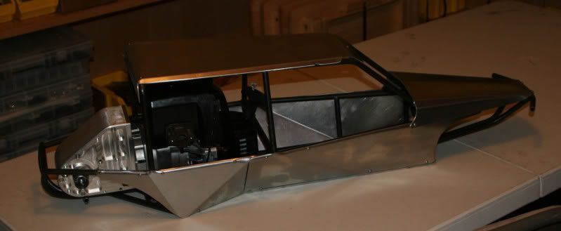
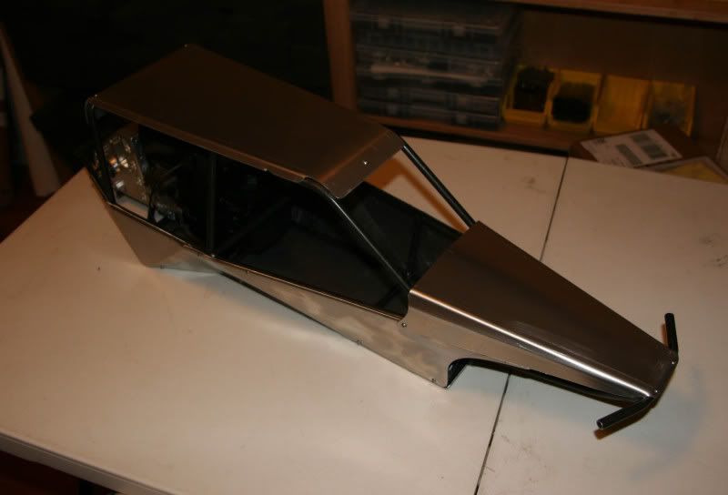
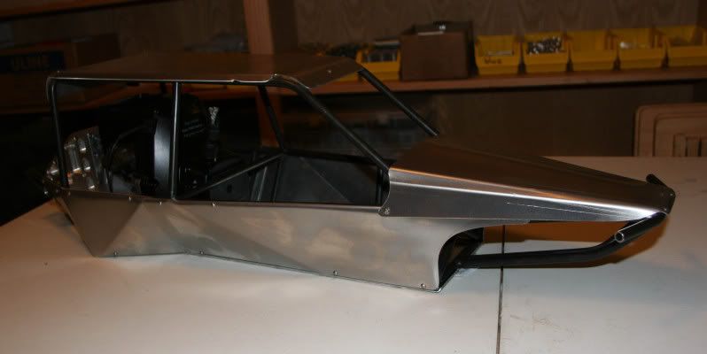
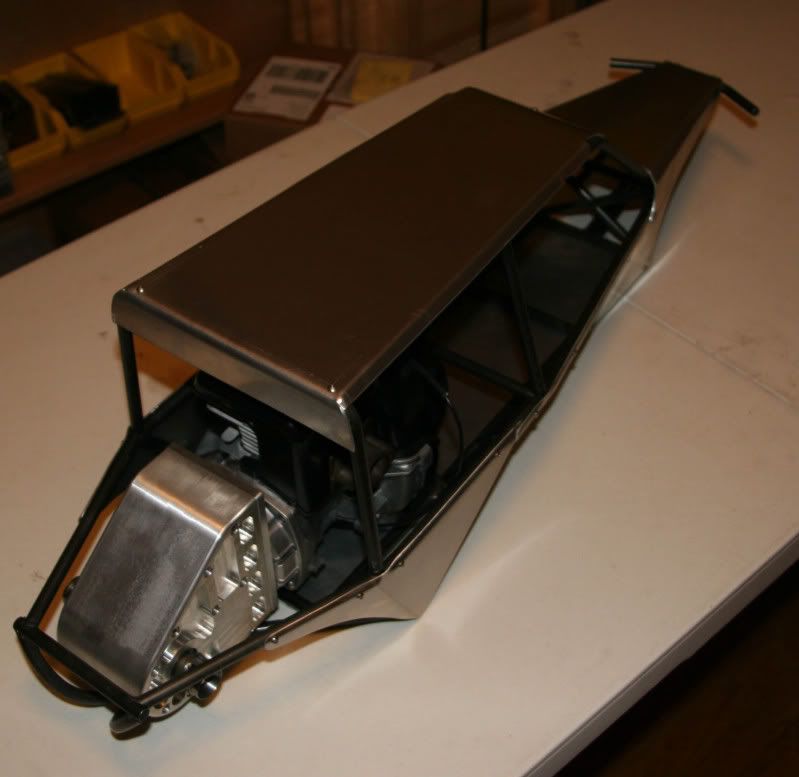
That's it for the chassis and body. I guess there was not much documented even though this was far more intense than the gear-box. The panels are attached to the chassis with small M3 screws. I drilled and tapped the frame tubing for these screws.
Tune in next for the suspension . . .
I wanted the chassis to wrap around the gear-box and protect it.
To keep the car scale I used a TGN X-Can for the exhaust. This had to be tucked away inside the chassis on the left-hand side
On the right hand side the intake filter sticks out a little bit but in the end that was OK.
I then worked from the rear of the chassis to the front. I kind of had an idea of the total length that I wanted the vehicle to be and I knew what components I wanted to fit into the chassis. I first fabbed up the lower portion of the chassis all the way to the nose then I proceeded onto the cage. There were so many things to consider at this point that it was very difficult to figure out which direction to go. I had to worry about keeping it proportionally scale. I wanted nice clean lines. The geometry had to be structurally sound. This is also where I had to start defining the suspension geometry. For the front I was going to use a typical A-arm set-up. In the rear I wanted to do a pseudo trailing arm. I also had to keep in mind on how I would get the engine and gear-box into and out of the frame.
Stage 1 of the frame. From here it should get easier.
A side view of the frame
An isometric view of the frame.
Another isometric view.
Some detail on the front end.
I kind of stopped keeping track of the progress from here but once the frame was done I welded on all of the tabs for the suspensions, motor mounts, gas tank mounts, radio gear etc. . . With the frame welded up I finished it with a nice black powder coat. This is my first time having stuff powder coated and there is nothing more breathtaking than a welded frame that has been powder coated.
The frame back from the powder coater.
Another shot of the finished frame.
Once the frame was roughed out I started in on the body panels. I can do almost anything with metal but when it comes to sheet metal I am at a loss. I can bend up a box any day of the week but when it comes to complex shapes like body panels I have mad respect for the guy that can do it and do it well. These panels were made from aluminum. There ended up being a total of seven panels. I think I wasted four times more material in screw-ups than what was actually used for the final panels.
That's it for the chassis and body. I guess there was not much documented even though this was far more intense than the gear-box. The panels are attached to the chassis with small M3 screws. I drilled and tapped the frame tubing for these screws.
Tune in next for the suspension . . .
09-10-2009, 11:13 PM
#5
Senior Member
Thread Starter
My Feedback: (6)
Join Date: Jan 2004
Location: Los Altos Hills, CA
Posts: 491
Likes: 0
Received 0 Likes
on
0 Posts
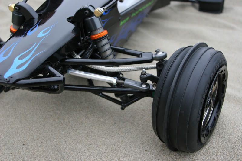
Unfortunately I didn't do much documentation on this either. I imagine I was probably feeling the crunch of RCX and not wasting time for lots of photos. For this build I wanted to do something that I had never seen done before. I wanted to make suspension arms from chromoly tubing. The beauty of chromoly is that if you do it right you can make a super strong assembly that is also relatively light weight. When I was done with these arms they were incredibly stiff but also lighter than most aluminum arms out there. All the suspension arms pivoted on special bearing grade plastic bushing. For the front lower arms I machined some nice little rod ends from aluminum that sandwiched the pivot balls. These bolted up to the chromoly arms. To make sure that I got the geometry correct and that both the right and left side were matched, I first designed the suspension geometry in AutoCAD and then made a clever little welding fixture for the arms. With out the welding fixture I never would have been able to get these arms right.
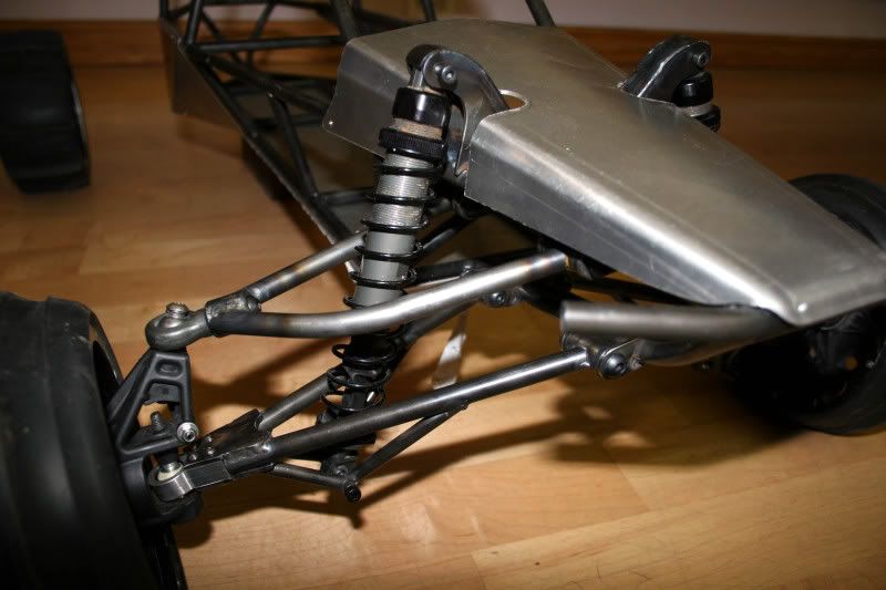
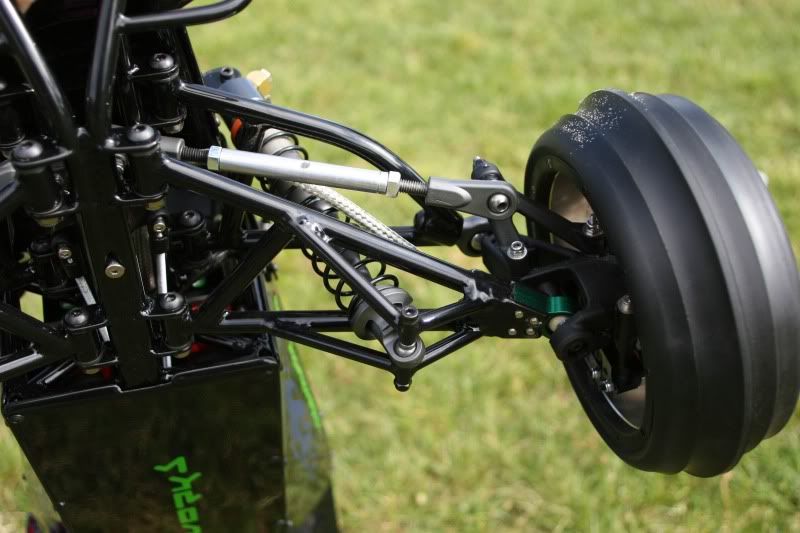
Here you can see the front suspension arms. Notice the intricate tubing ssembly where the shock mounts to the arm. Just like the real deal.
Here is the front end without the nose piece.
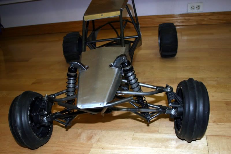
The front end mocked up.
More front end suspension.
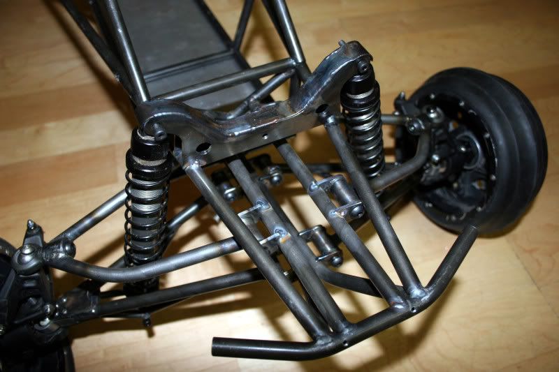
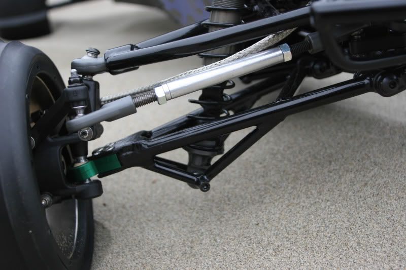
For the rear suspension I didn't really know what I was doing. I thought about doing a four link set-up but wanted to keep it simple I ended up with what I call a pseudo trailing arm suspension. Basically its a trailing/conventional arm cocked at a 45 deg angle. The camber of the wheel is set by an upper link. The geometry is such that the camber increases as the suspension compresses. I believe this is desirable for off-road. Don't know about sandrails though.
Here is the rear suspension mocked up.
The rear suspension from the top.
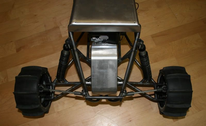
Another top view of the rear suspension.
The suspension finished.
Finished suspension.
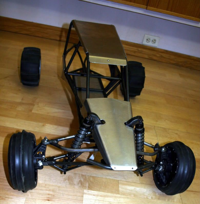
She's a rolling chassis.
That is mostly it. Most of the grunt work is done. Now it's onto the internals of the car. It's time to breath some life into this beast.
Tune in next for the final stages of the build. . .
Here you can see the front suspension arms. Notice the intricate tubing ssembly where the shock mounts to the arm. Just like the real deal.
Here is the front end without the nose piece.
The front end mocked up.
More front end suspension.
For the rear suspension I didn't really know what I was doing. I thought about doing a four link set-up but wanted to keep it simple I ended up with what I call a pseudo trailing arm suspension. Basically its a trailing/conventional arm cocked at a 45 deg angle. The camber of the wheel is set by an upper link. The geometry is such that the camber increases as the suspension compresses. I believe this is desirable for off-road. Don't know about sandrails though.
Here is the rear suspension mocked up.
The rear suspension from the top.
Another top view of the rear suspension.
The suspension finished.
Finished suspension.
She's a rolling chassis.
That is mostly it. Most of the grunt work is done. Now it's onto the internals of the car. It's time to breath some life into this beast.
Tune in next for the final stages of the build. . .
09-10-2009, 11:15 PM
#6
Senior Member
Thread Starter
My Feedback: (6)
Join Date: Jan 2004
Location: Los Altos Hills, CA
Posts: 491
Likes: 0
Received 0 Likes
on
0 Posts
The final stages are here. I started this project towards the end of February and wrapped it up in mid April just in time for RCX. So a little under two months. I have invested probably more the 400 hrs into the project over a two month period.
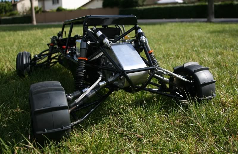
For the gas tank I wanted to use the HPI baja gas tank. I machined a plate from carbon fiber to mount the gas tank, steering servos, and front brake servo to. I also machined another plate from carbon fiber to support the rear brake servo. For radio gear I designed the steering to use dual Multiplex Rhino Servos. I then used a Hitec 7955 for the front brakes and a Hitec 7955 for the rear brakes. For the brakes I used two sets of the Baja Skunkworks brake kits. All of the electronics are powered from a 2S lipo battery with a castle creations regulator. And everything is controlled with a Futaba 3PK 2.4GHz FASST system.
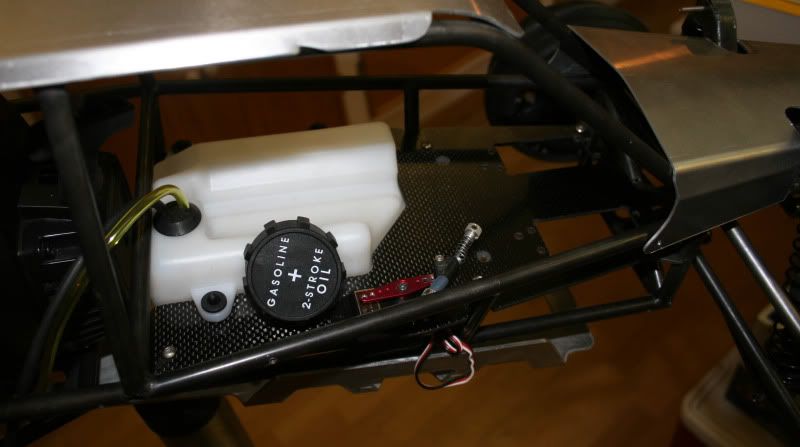
Here you can see the gas tank and carbon fiber servo plate.
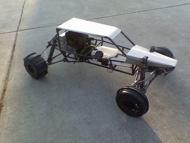
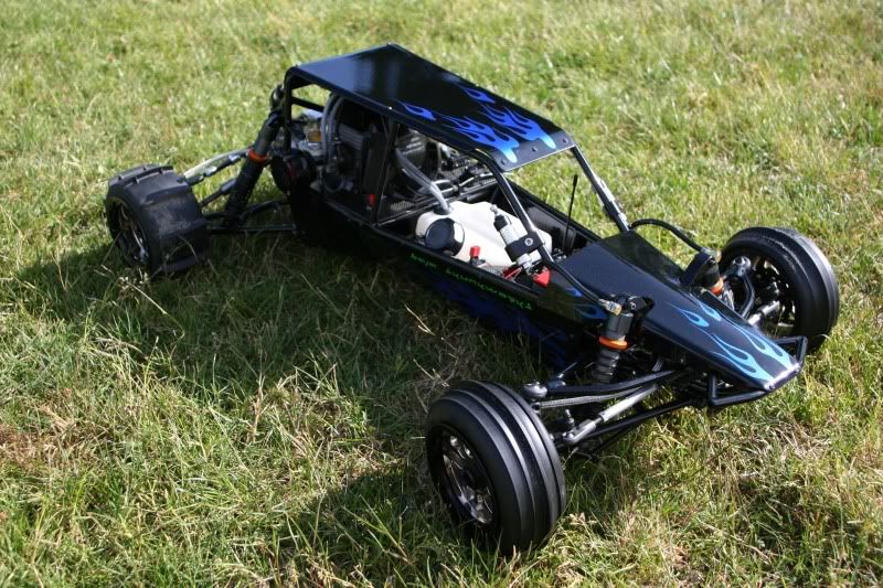
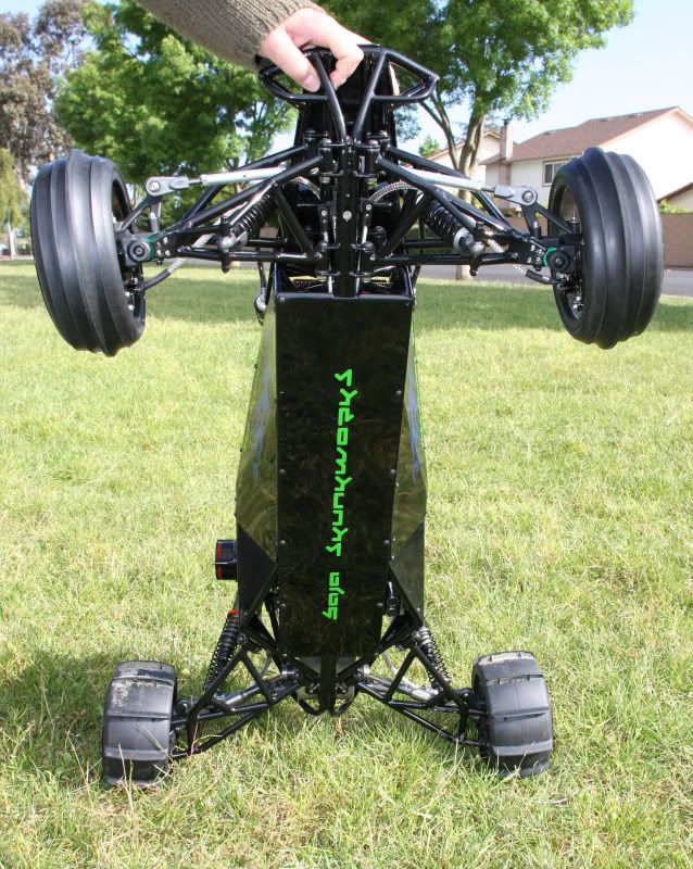
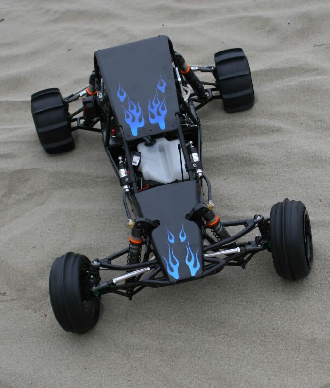
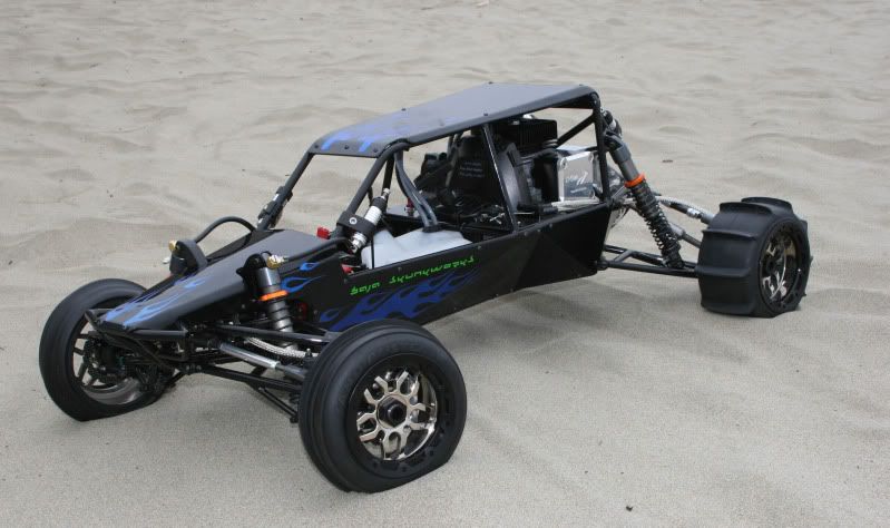
All of the body panels and suspension arms were finished with black powder coat. For the body panels I added some flair with my atempt at custom flames. I also threw on some simple company decals. To add to the scale I picked up some Threshold Rezzies and had them black anodized. The car is rolling on custom chrome plated Ramtech Rims thanks to Manny from Custom Street Toyz and FAST.
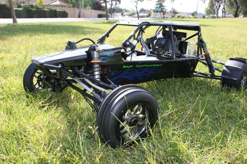
Looking like she's ready to pounce.
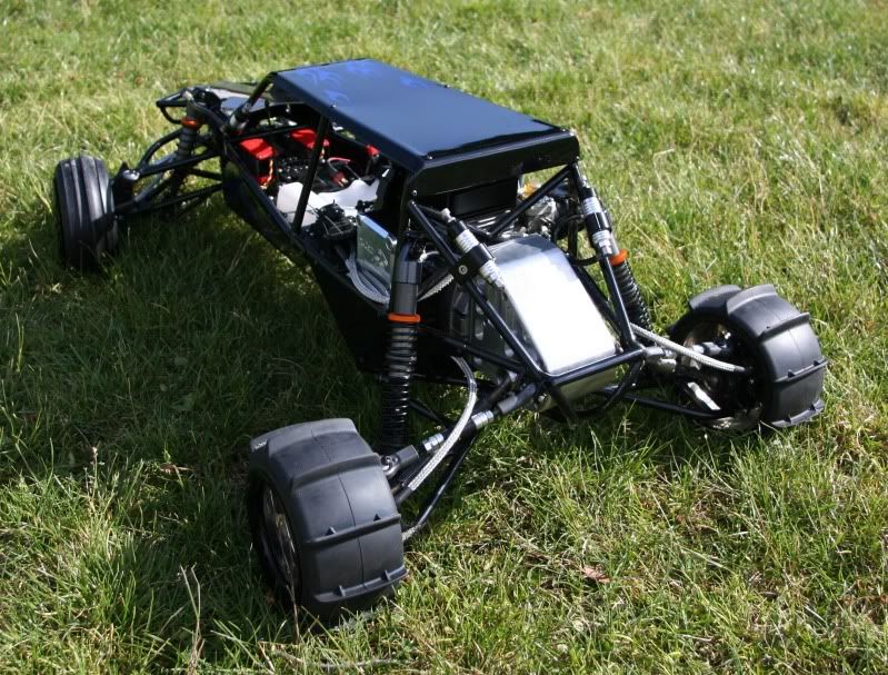
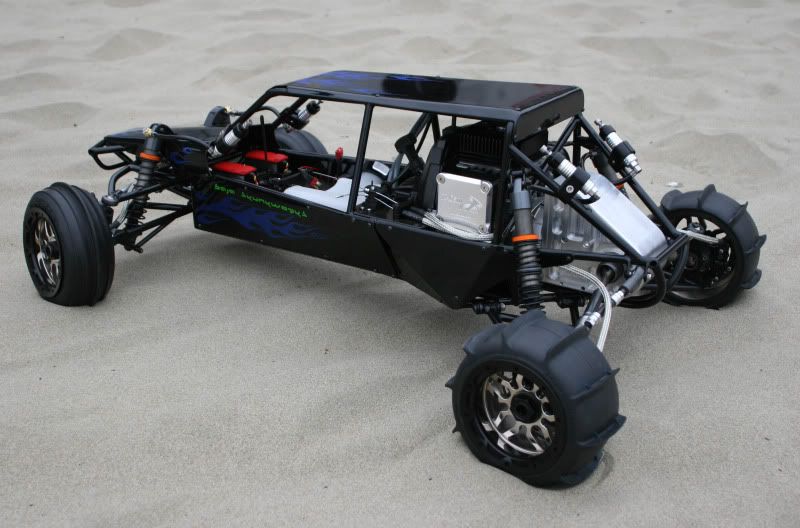
Looking good from the rear to.
Thanks to TGN for the motor and inspiration!
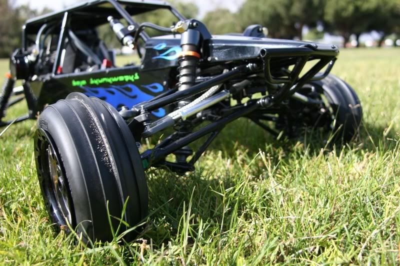
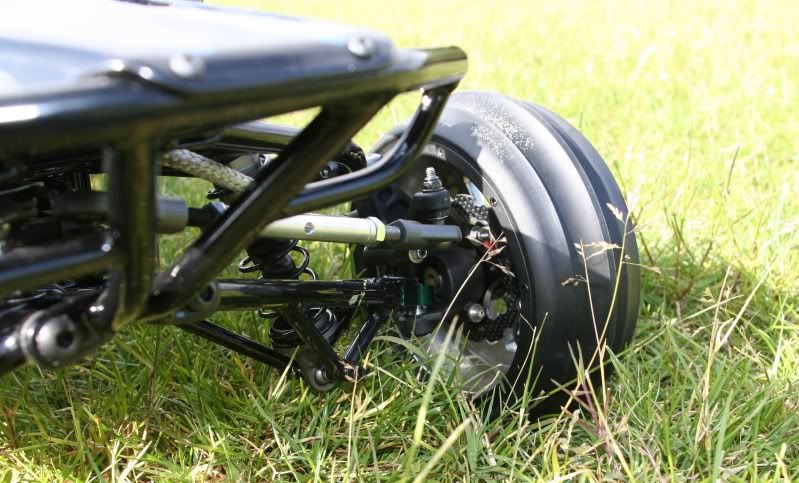
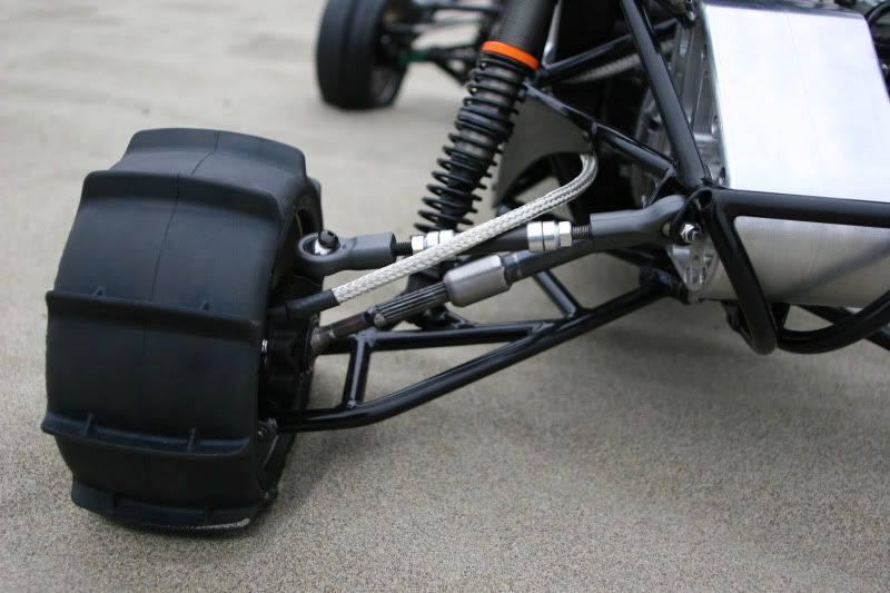
Close up on the rear. Notice the custom carbon fiber camber link and the telescoping drive shafts.
Here you can see the front disk brakes.
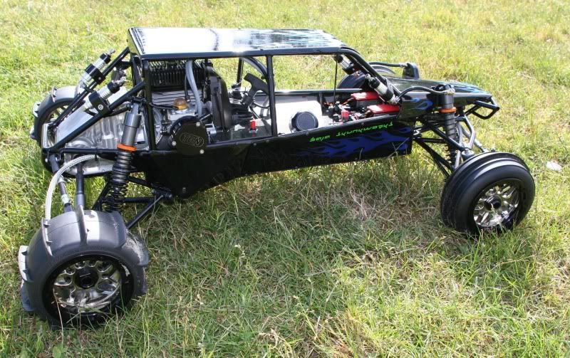
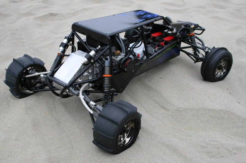
The belly of the beast. Check out the exhaust ports coming out of the bottom of the chassis.
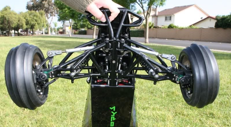
Close up of the front suspension. Notice the steering linkage and the servo saver hiding inside the frame.
Check out the intricacies of the front suspension.
And that's a wrap. Thanks for looking and thanks to those who helped with this project.
For the gas tank I wanted to use the HPI baja gas tank. I machined a plate from carbon fiber to mount the gas tank, steering servos, and front brake servo to. I also machined another plate from carbon fiber to support the rear brake servo. For radio gear I designed the steering to use dual Multiplex Rhino Servos. I then used a Hitec 7955 for the front brakes and a Hitec 7955 for the rear brakes. For the brakes I used two sets of the Baja Skunkworks brake kits. All of the electronics are powered from a 2S lipo battery with a castle creations regulator. And everything is controlled with a Futaba 3PK 2.4GHz FASST system.
Here you can see the gas tank and carbon fiber servo plate.
All of the body panels and suspension arms were finished with black powder coat. For the body panels I added some flair with my atempt at custom flames. I also threw on some simple company decals. To add to the scale I picked up some Threshold Rezzies and had them black anodized. The car is rolling on custom chrome plated Ramtech Rims thanks to Manny from Custom Street Toyz and FAST.
Looking like she's ready to pounce.
Looking good from the rear to.
Thanks to TGN for the motor and inspiration!
Close up on the rear. Notice the custom carbon fiber camber link and the telescoping drive shafts.
Here you can see the front disk brakes.
The belly of the beast. Check out the exhaust ports coming out of the bottom of the chassis.
Close up of the front suspension. Notice the steering linkage and the servo saver hiding inside the frame.
Check out the intricacies of the front suspension.
And that's a wrap. Thanks for looking and thanks to those who helped with this project.

 09-11-2009, 12:19 AM
#10
Member
Join Date: Sep 2009
Location: Staten Island,
NY
Posts: 82
Likes: 0
Received 0 Likes
on
0 Posts
Brice you have hands of gold my friend, your blood, sweat and tears show in everything you do, there is never any short cuts when I look at your work.
You have the master mind in designing and modifying, more importantly, you have the hands to create your ideas....now that is simply amazing.
You are blessed.
Pete
You have the master mind in designing and modifying, more importantly, you have the hands to create your ideas....now that is simply amazing.
You are blessed.
Pete
09-11-2009, 12:59 AM
#11
Senior Member
Join Date: Jul 2006
Location: , AUSTRALIA
Posts: 771
Likes: 0
Received 0 Likes
on
0 Posts
this is a brillient build seen a tons of pics of this beast and cant fault it... simply amazing...
havent seen any vids though??? does it go??
havent seen any vids though??? does it go??


 09-11-2009, 03:02 AM
#15
Senior Member
Join Date: Aug 2006
Location: hometown, AUSTRALIA
Posts: 252
Likes: 0
Received 0 Likes
on
0 Posts
Amazing build, you deserve all the pats on the back you get. I could only wish for the equipment you have and the skills you have shown.
WELL DONE MATE
WELL DONE MATE
09-11-2009, 10:06 AM
#17
Senior Member
My Feedback: (2)
Join Date: Jul 2008
Location: Cincinnati,
OH
Posts: 110
Likes: 0
Received 0 Likes
on
0 Posts
good freakin god man! that is absolutely amazing! cant even imagine what an MT would like like if you built it!..hint hint  josh
josh
josh
09-11-2009, 11:42 AM
#18
Senior Member

Join Date: Jan 2008
Location: Some where in
Posts: 3,716
Likes: 0
Received 0 Likes
on
0 Posts
ORIGINAL: brice_arnold
The final stages are here. I started this project towards the end of February and wrapped it up in mid April just in time for RCX. So a little under two months. I have invested probably more the 400 hrs into the project over a two month period.
For the gas tank I wanted to use the HPI baja gas tank. I machined a plate from carbon fiber to mount the gas tank, steering servos, and front brake servo to. I also machined another plate from carbon fiber to support the rear brake servo. For radio gear I designed the steering to use dual Multiplex Rhino Servos. I then used a Hitec 7955 for the front brakes and a Hitec 7955 for the rear brakes. For the brakes I used two sets of the Baja Skunkworks brake kits. All of the electronics are powered from a 2S lipo battery with a castle creations regulator. And everything is controlled with a Futaba 3PK 2.4GHz FASST system.
Check out the intricacies of the front suspension.
And that's a wrap. Thanks for looking and thanks to those who helped with this project.


 09-12-2009, 02:25 PM
#24
Senior Member

Join Date: Jul 2005
Location: Torchy the Fiery Fast RC Turtl
Posts: 10,544
Likes: 0
Received 0 Likes
on
0 Posts
Brice, welcome back! And from the looks of this serious beauty, you left no stone unturned! Designed from the ground up and everything literally fabricated from your own design! Very impressive! A true masterpiece! And when I say masterpiece, I mean it. This ranks up there with a single person made work of art (like how Davinci himself painted the Mona Lisa). Sure there are other RCs that can be very nice too, but this one is designed and made just by you from the ground up. Even a Cleon took several people to design and make, and it is mass produced by mass production machinery; you made this solely by your self, and that is this work and other similarly scratch built fabricated RCs that are professional and industrial grade are the Picasos and DaVincis of RCs!
Jim
P.S. I hope you designed this to mount LoJack or something onto it; I hope those Dee-bags that stole your other RC are getting the crap kicked out of them really badly. To this day, it still breaks my heart to know that your other masterpiece was blatantly stolen like it was.
Jim
P.S. I hope you designed this to mount LoJack or something onto it; I hope those Dee-bags that stole your other RC are getting the crap kicked out of them really badly. To this day, it still breaks my heart to know that your other masterpiece was blatantly stolen like it was.