


Adding RDS hidden linkages
 03-24-2015, 04:17 AM
#1


They say the work of a scale aircraft is never finished and that is very true so I am at it again. I have always hated the ugly linkages on the rudders of my F22. To make matters worse the vertical stabs are bent out so they really stick out like a sour thumb.
The challenges on this plane is flutter. As most know I fly this plane HARD and allot so I must have a solid linkage. To make matters worse several of F22s (yellow and jetlegend) have crashed or rudders have flown off due to rudder flutter. So their is allot of force on these rudders. After lots of reading I decided on the RDS system. I have seen some say they had play after the install and others say they are rock solid. So I am going to give it a try.
I don't need much rudder throw so I went with the rods that have only a light bend for more torque and less throw and increased resolution. Not sure if this is going to work well or not but will include my findings for all that are thinking about it. Topgun is only a month away so this is going to get done fast.
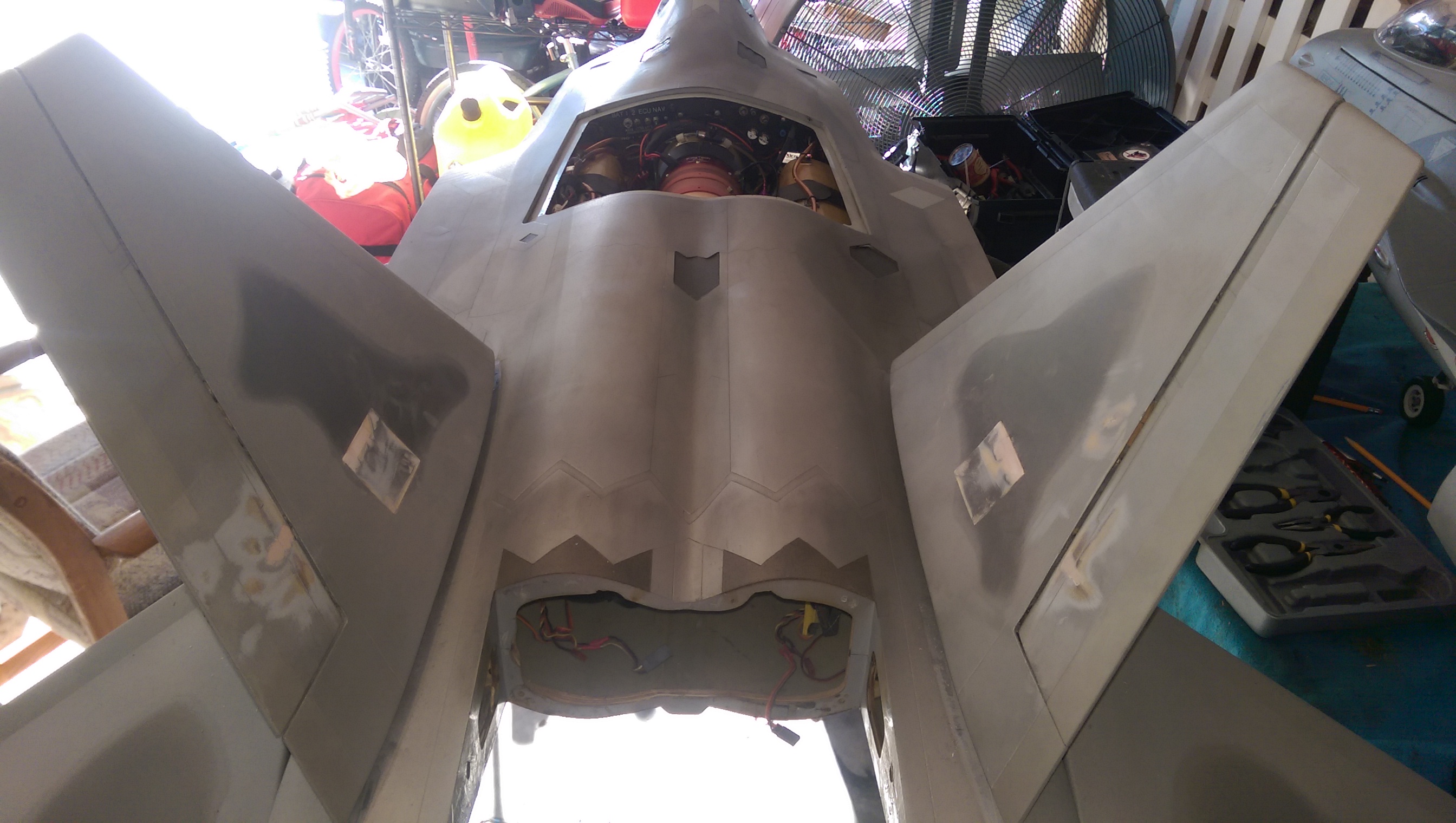
A pic before I start.
The challenges on this plane is flutter. As most know I fly this plane HARD and allot so I must have a solid linkage. To make matters worse several of F22s (yellow and jetlegend) have crashed or rudders have flown off due to rudder flutter. So their is allot of force on these rudders. After lots of reading I decided on the RDS system. I have seen some say they had play after the install and others say they are rock solid. So I am going to give it a try.
I don't need much rudder throw so I went with the rods that have only a light bend for more torque and less throw and increased resolution. Not sure if this is going to work well or not but will include my findings for all that are thinking about it. Topgun is only a month away so this is going to get done fast.
A pic before I start.
 03-24-2015, 04:21 AM
#2
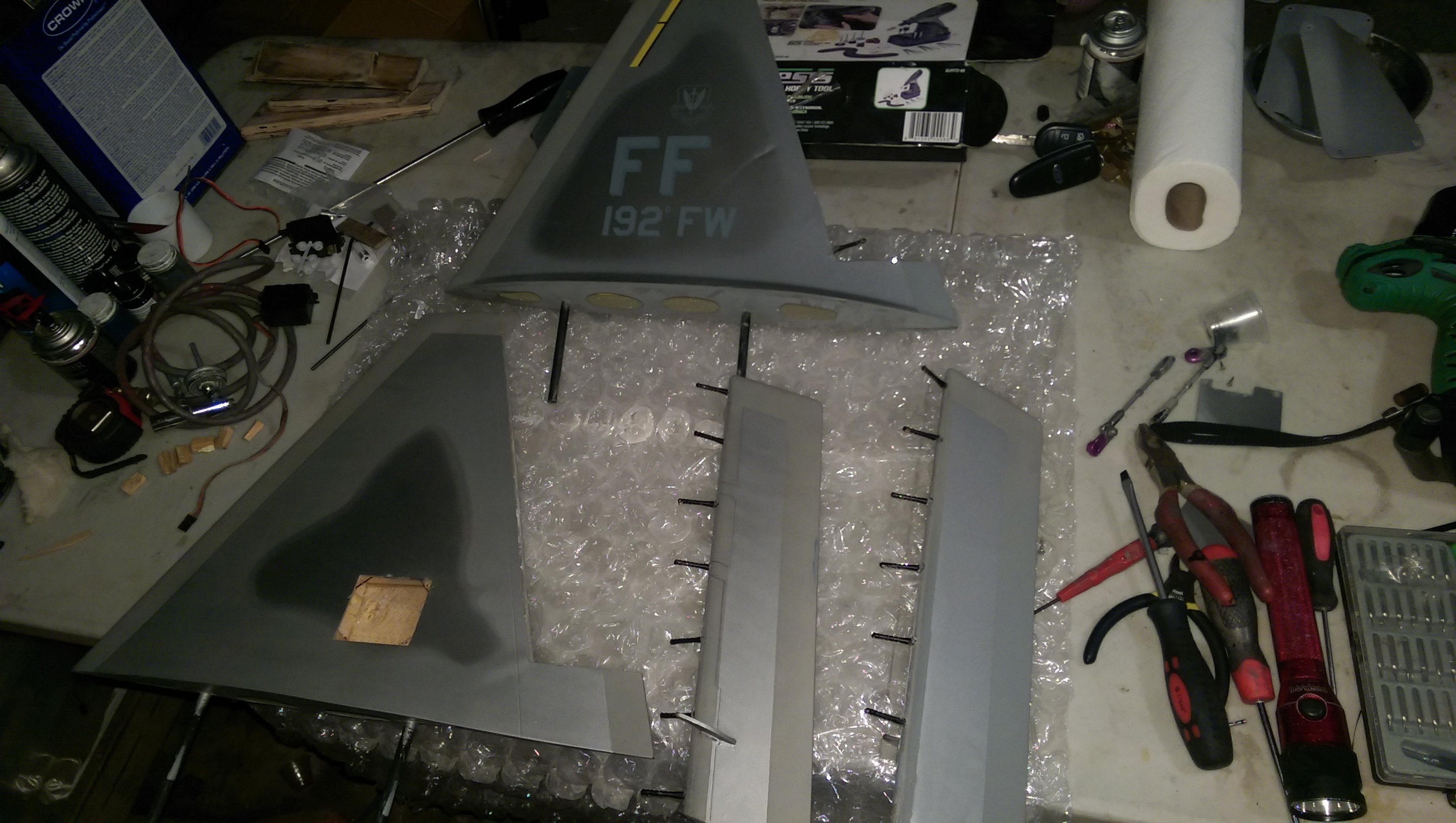
First step was to remove the vertical stabs. Then remove servos and rudders. The rudders where pretty tough since they have so many hinges. I think I even added some extra ones don't remember. I removed the rudder by simply yanking it out with every muscle I had. 
03-24-2015, 09:22 AM
#4

Gunradd, I have serious concerns with that setup, specially on a jet. You are relying on a relatively small diameter rod to provide control surface stiffness.
The rod, even a steel rod, has a relatively low torsional yield. The longer the rod is, the more succeptible it is to torsion. Add air loads, vibration, the rod will wear out. The components that hold it together will wear too.
If flutter is your concern, what you are doing is not better than your original setup, although it does look cool.
David
03-25-2015, 04:53 PM
#7
Thanks David and Chris. The rods are bent then hardend . They are 1/8 and crazy strong. I was worried also but after talking to some people that have used them in bigger models I felt better.
I have them installed now and it's time for paint. I can say these have no play at all and seem to be better then the original linkages.
I have them installed now and it's time for paint. I can say these have no play at all and seem to be better then the original linkages.

 03-26-2015, 07:10 AM
#12
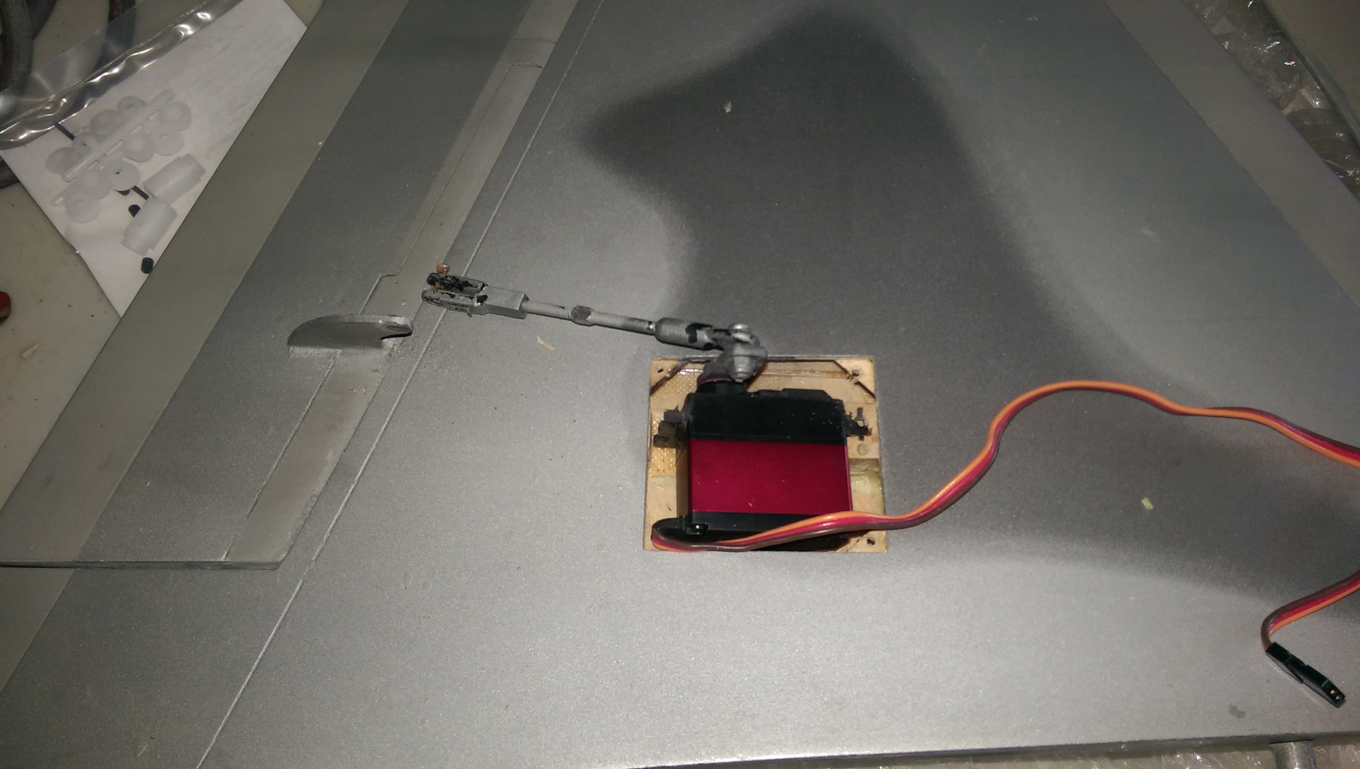
Matt I just put some blue tape on the outside of the stab to make a temporary line for where the rod needed to go and used a long drill bit and followed the angle the best I could. On the rear hinge line the vertical stab has a balsa strip installed that the hinges go into. I used a dremel to remove about a 1 inch section of the balsa where the rod went through. I then glued in a ply block in its place and drilled a hole through it for the rod. Even with the one inch hole and no support I checked the linkage for play and was surprised to find it didn't have much even though it was only being held by the servo.
Keith I am not sure what its made out of. Looks like some kind of plastic not sure. But since its only getting a rotational force so it seems to be plenty strong.
It will be a few weeks until I get time to fly but I will give a full report on that flight.
Keith I am not sure what its made out of. Looks like some kind of plastic not sure. But since its only getting a rotational force so it seems to be plenty strong.
It will be a few weeks until I get time to fly but I will give a full report on that flight.
03-26-2015, 02:16 PM
#14
I am using the hard plywood as the bushing and the hinge line is on the rudder side.If I find the ply wood is getting wear I could always slide a brass tube over it but doubt it will be needed. I used a grinding wheel to cut a slot in the rudder then used hysol to secure the pocket inside the rudder.


 04-01-2015, 03:23 PM
#20
Thanks Sean
Flight report... Got 8 flights in today and it flew great. I pushed the plane to its limits and no flutter and perfect centering. I like them so much next im going to do the flaps and ailerons so all the linkages are hidden
So for anyone on the fence if these will work in our jets in my case I have a surface that's prone to flutter (several have been lost due to rudder flutter) and it worked out great pushing the aircraft to its limits. When I do the ailerons and flaps ill post more.


