


Turbine Conversion Of 80mm Freewing A-10 To Single X-45 Turbine
 07-15-2022, 05:21 PM
#51

Thread Starter
My Feedback: (20)
A-10 paint codes
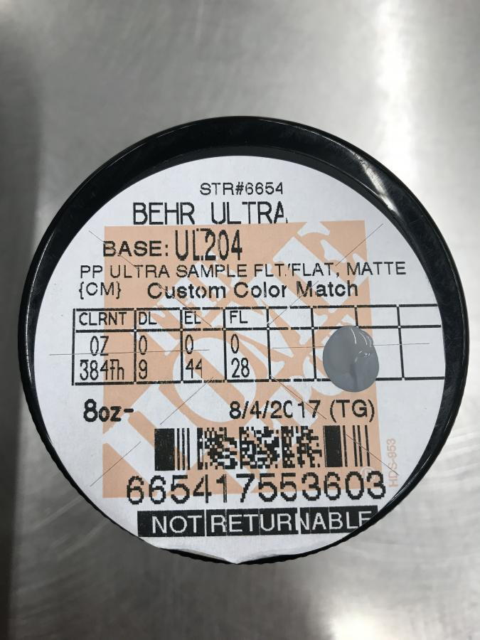
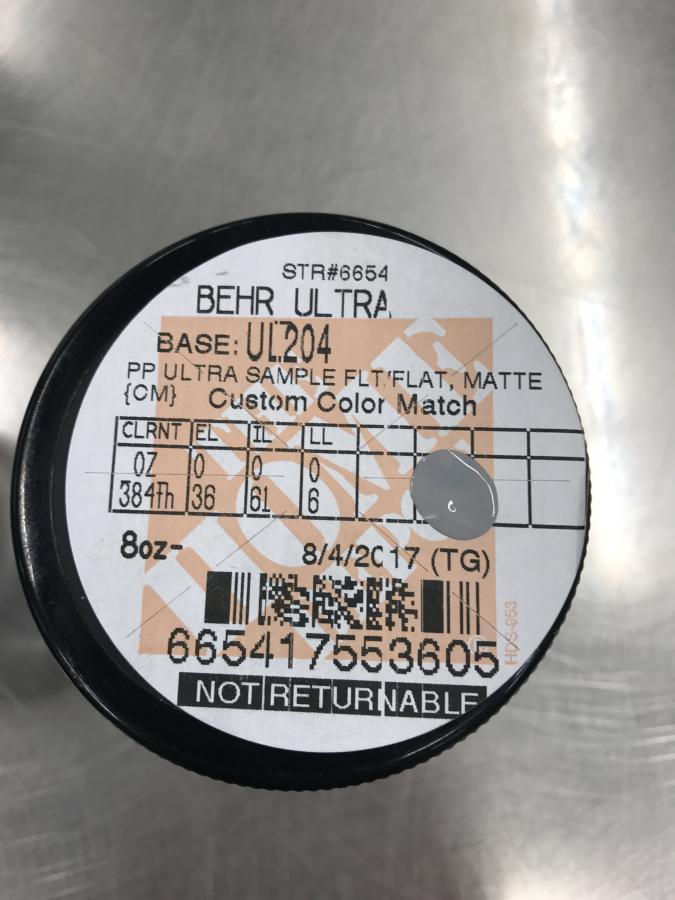
I found the above Home Depot paint codes in several places in the other A-10 threads so I took these photos to HD to get a match for the dark and light grey colors. The paint lady looked and told me these were from 2017 and they no longer used this brand of paint and all the codes are different now but she could match them.
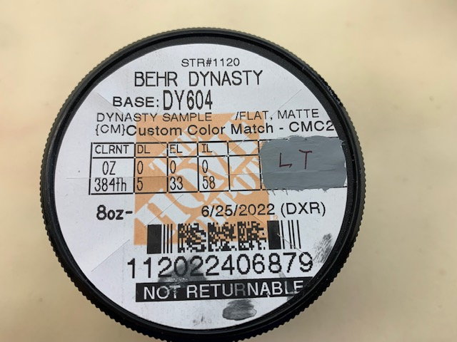
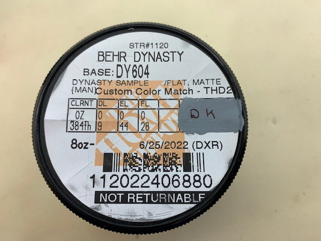
After a few minutes at the computer she mixed these codes for the light grey and dark grey. I got home and tested them and they are nearly perfect. The light grey is what I used to repaint the rear end of the fuse and pipe that is in the photos above.
I found the above Home Depot paint codes in several places in the other A-10 threads so I took these photos to HD to get a match for the dark and light grey colors. The paint lady looked and told me these were from 2017 and they no longer used this brand of paint and all the codes are different now but she could match them.
After a few minutes at the computer she mixed these codes for the light grey and dark grey. I got home and tested them and they are nearly perfect. The light grey is what I used to repaint the rear end of the fuse and pipe that is in the photos above.
 07-16-2022, 06:14 AM
#52
Was just at the field with a local pilot who was flying one of these on electric. After seeing my X45 converted FW F22 he mentioned people were converting the A10’s to turbine. Amazing work you’ve done there - way more reengineeirng than I would have expected. Kudos to you
cheers,
PaulD
cheers,
PaulD
07-16-2022, 05:40 PM
#54
Thread Starter
My Feedback: (20)
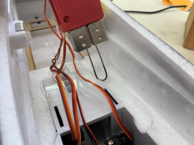
Turbine and pipe install
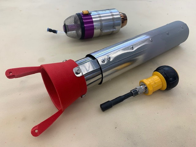
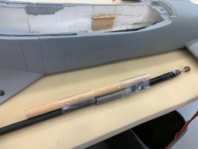
I got the heat treated cone attached to the pipe with 4 bolts and lock nuts.
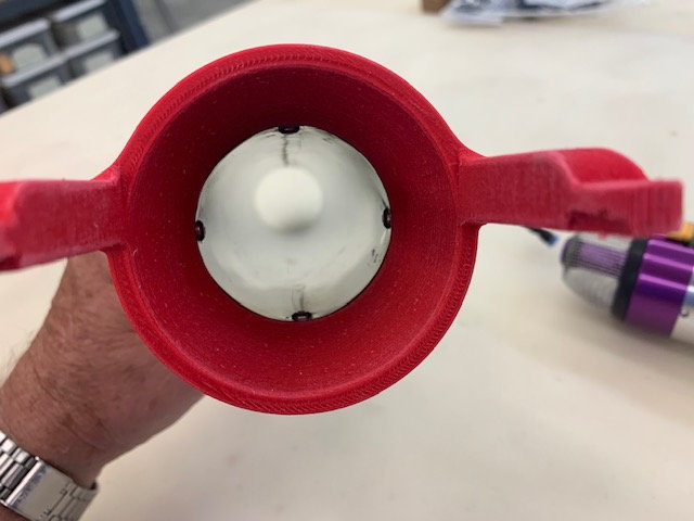
View from the front of the pipe
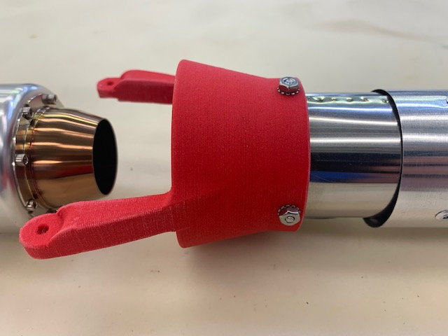
Lock nuts on outside of pipe bell mouth
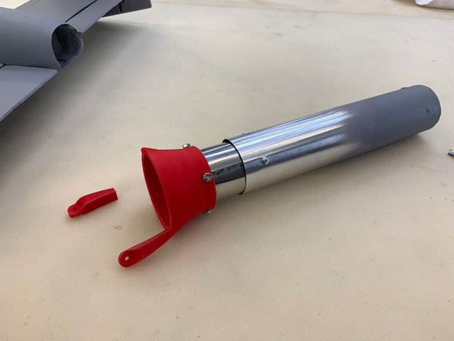
And then the fun began... WIth the servo wires in the pipe channel covered with the ceramic heat blanket, and the pipe the bell firmly bolted on, I could not slide the pipe into the channel with out scraping the ceramic heat blanket off the servo wires. After seeing this I tried to push the bell down into position but it would not fit with out flexing the mounting arms. And after heat treating the material is more brittle and one arm broke off. AARRGGHH!
After a long break I came back to the shop and started over. I replaced the cracked bell with a new one. Glad I made some spares. Next I removed all the ceramic blanket material I had glued in over the servo wires. This was not very easy trying to get it out of the pipe channel. Next I modified the Dremel flex cable with a dowel to make a longer reach back into the pipe channel.
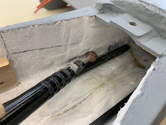
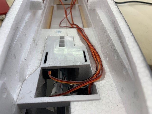
I ground the foam away to make a recessed wire channel on each side to get the servo wires below the surface of the foam. Next I cut away enough foam in front of the turbine to get the pipe bell down inside the fuse and slide it straight back without the front of the pipe being raised. Then I replaced the ceramic felt blanket material over the servo wires as before.
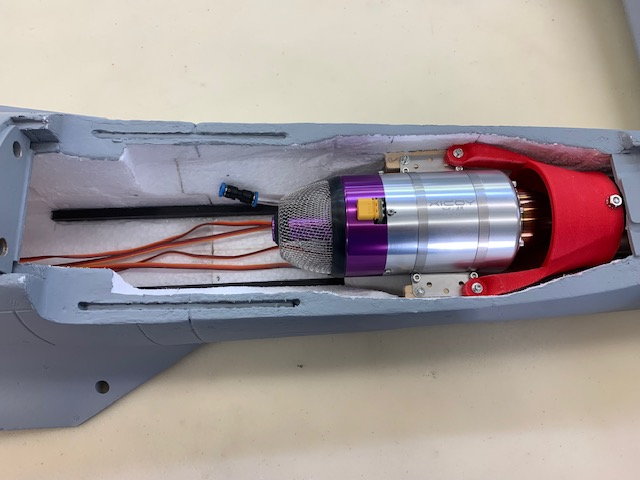
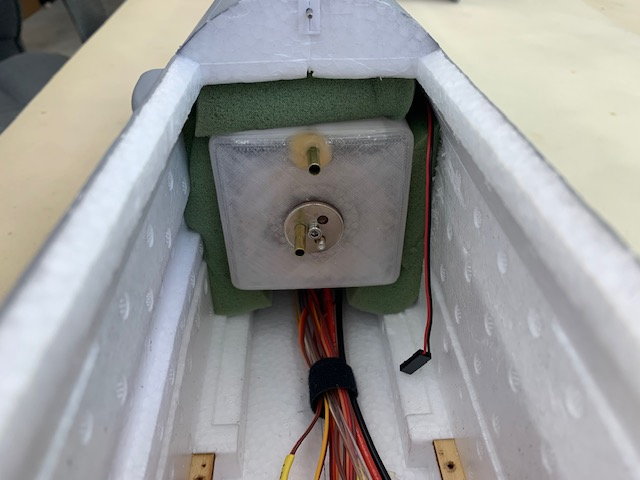
Finally after much fussing I got the pipe and turbine mounted. This photo shows where the foam was removed forward of the turbine to allow the bell mouth to slip down inside the fuse to align the pipe before pushing it back.
Not perfect but close enough. Called it a day.
I got the heat treated cone attached to the pipe with 4 bolts and lock nuts.
View from the front of the pipe
Lock nuts on outside of pipe bell mouth
And then the fun began... WIth the servo wires in the pipe channel covered with the ceramic heat blanket, and the pipe the bell firmly bolted on, I could not slide the pipe into the channel with out scraping the ceramic heat blanket off the servo wires. After seeing this I tried to push the bell down into position but it would not fit with out flexing the mounting arms. And after heat treating the material is more brittle and one arm broke off. AARRGGHH!
After a long break I came back to the shop and started over. I replaced the cracked bell with a new one. Glad I made some spares. Next I removed all the ceramic blanket material I had glued in over the servo wires. This was not very easy trying to get it out of the pipe channel. Next I modified the Dremel flex cable with a dowel to make a longer reach back into the pipe channel.
I ground the foam away to make a recessed wire channel on each side to get the servo wires below the surface of the foam. Next I cut away enough foam in front of the turbine to get the pipe bell down inside the fuse and slide it straight back without the front of the pipe being raised. Then I replaced the ceramic felt blanket material over the servo wires as before.
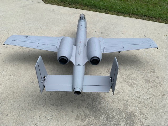
Finally after much fussing I got the pipe and turbine mounted. This photo shows where the foam was removed forward of the turbine to allow the bell mouth to slip down inside the fuse to align the pipe before pushing it back.
Not perfect but close enough. Called it a day.
The following users liked this post:
BadBill (07-18-2022)
07-18-2022, 01:31 PM
#55
Thread Starter
My Feedback: (20)
Work starts on front end
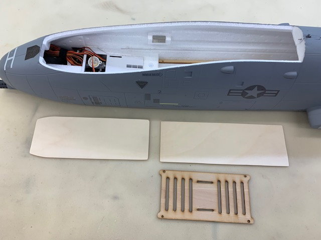
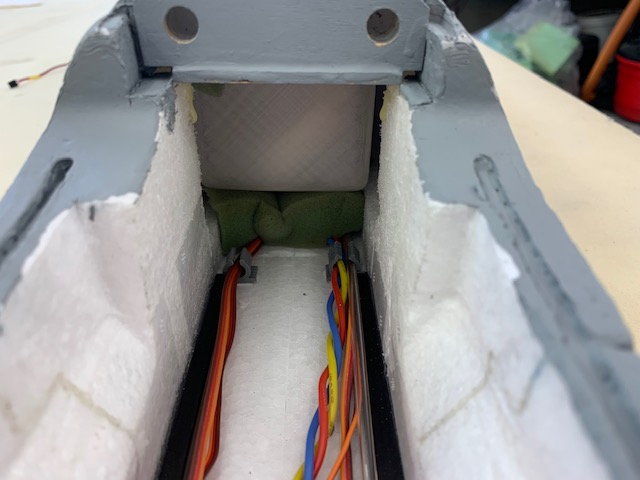
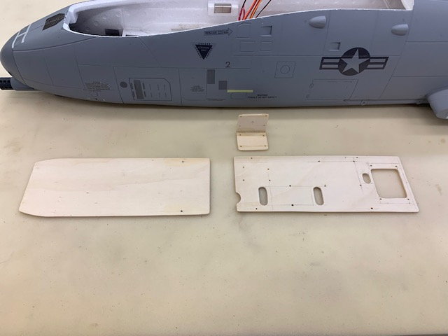
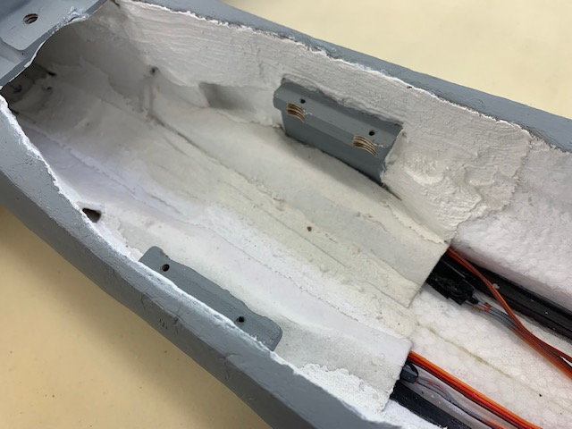
Now that the turbine and pipe are done I started looking at the front end. First step was to make bigger equipment trays to go below the cockpit. I added some space to the rear tray and reclaimed some unusable space above the nose gear on the front tray.
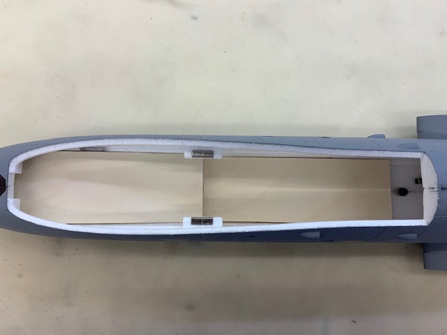
Dry fit of trays under cockpit. Now starts the hard part, planning and laying out the wire jungle!
Now that the turbine and pipe are done I started looking at the front end. First step was to make bigger equipment trays to go below the cockpit. I added some space to the rear tray and reclaimed some unusable space above the nose gear on the front tray.
Dry fit of trays under cockpit. Now starts the hard part, planning and laying out the wire jungle!
07-19-2022, 04:34 PM
#56
Thread Starter
My Feedback: (20)
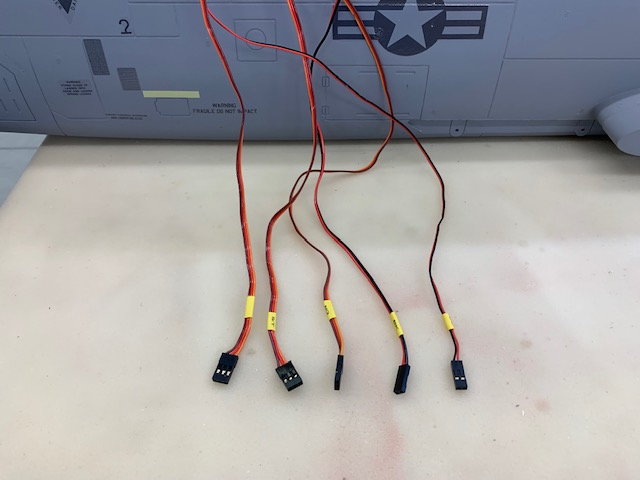
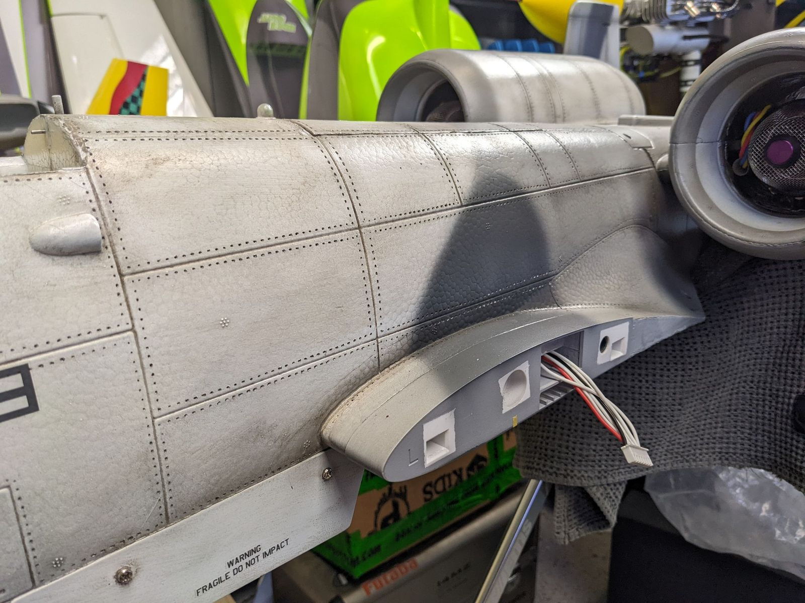
Splitting flap and aileron signal wires for separate channels
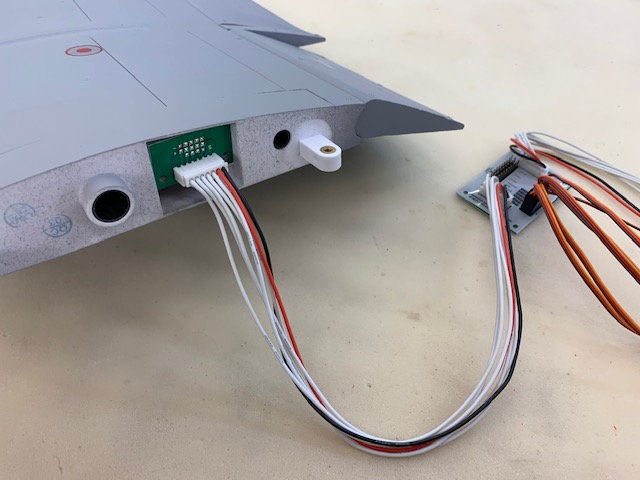
The normal FW wiring harness has flaps and ailerons connected through PC boards to operate on a single channel each. I want to split them off so each flap and aileron has a separate channel
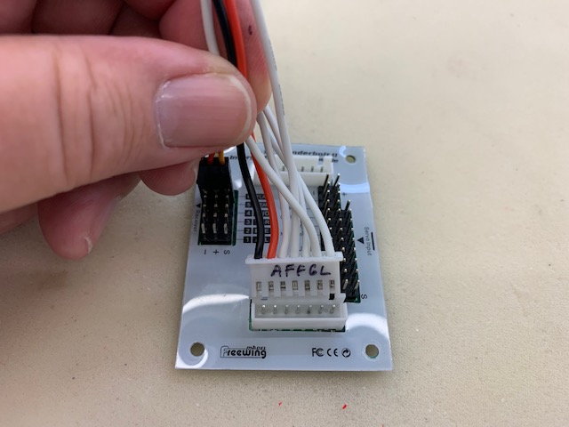
FW made it easy to locate each function wire on the back of the wing plug PC board
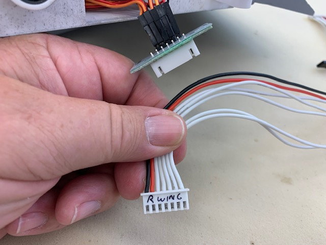
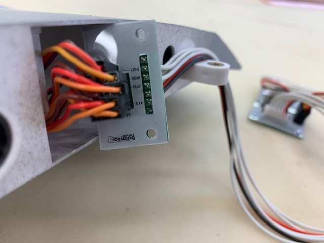
Plugs were labeled
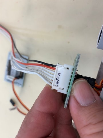
Each signal wire marked...LGFFA is Lights, Gear, Flap, Flap, AIleron
Wires marked on other end of the cable that will plug into the board or receiver
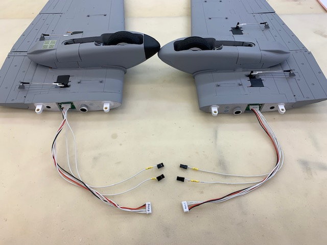
Signal wires for ailerons and flaps split off from cable to plug directly into receiver. Power to each wing comes through the PC board and plugs into the wing.
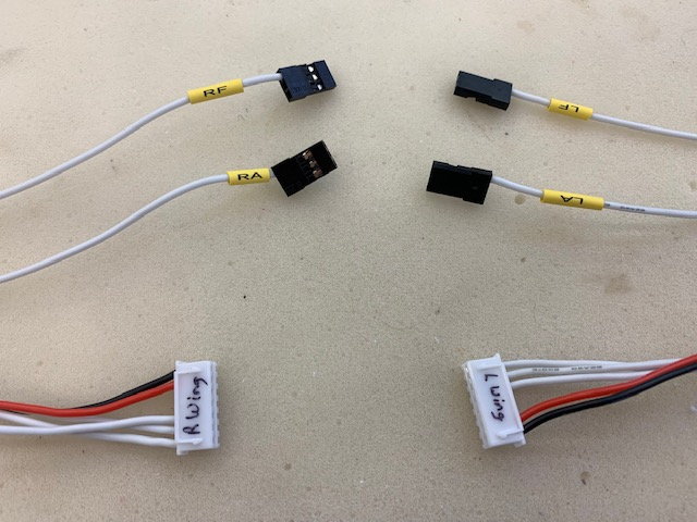
I expected two flap signals per wing but found out after cutting the first flap signal wire that the flap signal leads on each wing were connected together in the wing root PC board and could not be separated with out modifying the PC board. Definitely not worth it as both flaps tracked well together on each wing. This will save 2 extra channels from what I had expected and make the Jeti setup using the Butterfly/Flap function easier.
The normal FW wiring harness has flaps and ailerons connected through PC boards to operate on a single channel each. I want to split them off so each flap and aileron has a separate channel
FW made it easy to locate each function wire on the back of the wing plug PC board
Plugs were labeled
Each signal wire marked...LGFFA is Lights, Gear, Flap, Flap, AIleron
Wires marked on other end of the cable that will plug into the board or receiver
Signal wires for ailerons and flaps split off from cable to plug directly into receiver. Power to each wing comes through the PC board and plugs into the wing.
I expected two flap signals per wing but found out after cutting the first flap signal wire that the flap signal leads on each wing were connected together in the wing root PC board and could not be separated with out modifying the PC board. Definitely not worth it as both flaps tracked well together on each wing. This will save 2 extra channels from what I had expected and make the Jeti setup using the Butterfly/Flap function easier.
The following users liked this post:
ww2birds (07-20-2022)
07-26-2022, 05:37 PM
#57
Thread Starter
My Feedback: (20)
Nose Gear Modifications and Brake install
Hot wire cutting a channel for nose gear well wires under the forward equipment tray
Channel allows wires to run under the tray when it is flat on the foam floor
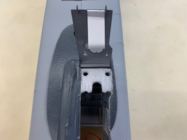
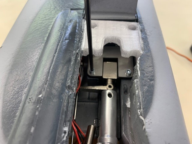
After reading several threads about how the nose gear has a lot of slop and a weak mount I planned on two mods. First is the standard nose strut brace that keeps the strut from back bending forces on rough terrain. I only fly from grass so I thought this would be helpful. I downloaded the brace from Thingiverse and printed it in PETG. Fitting it was a fuss to get the landing light and brakes wires to not get tangled with the steering arm and gear retraction. I also added a single nose wheel brake to comply with AMA rules and to make stopping in the pits easier when taxing back after landing. Brakes are normally not needed when landing my foamies in the grass.
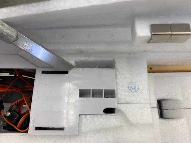
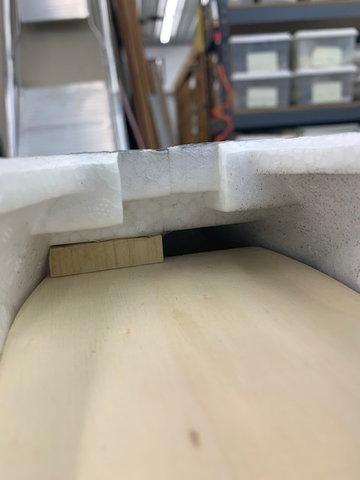
The second mod was to strengthen the nose gear mounting plate. It is plastic and tends to break if bounced. I copied this mod directly from the A-10 threads. It basically backs up the plastic mounting plate with hard wood and uses longer screws to get into the wood backing. First step was to remove the foam from above the right side mounting holes. I used a long knife blade to cut and needle nose pliers to pull out the foam.
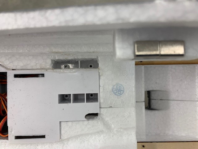
Nose gear mounting holes seen from above
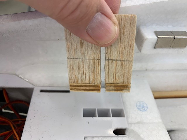
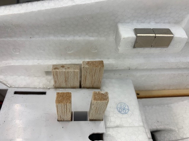
Balsa and 1/4" plywood braces fabricated
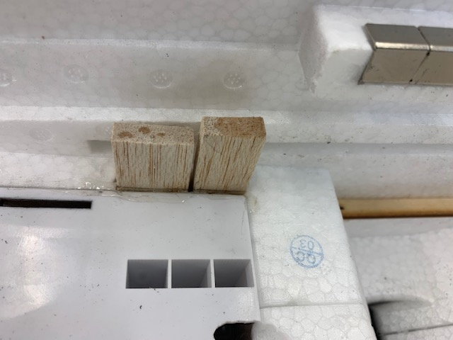
Braces inserted into the holes above the gear mount
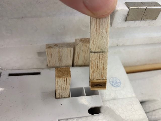
Left side slots are a a little smaller
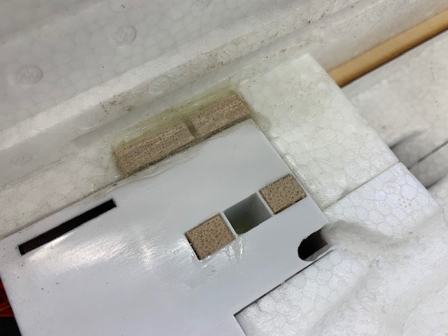
Braces epoxied into the slots and excess epoxy wiped away
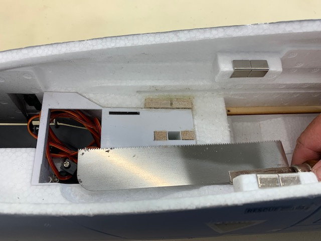
Flush cut saw use to cut the braces flush with the foam floor
Lightly sanded and done
Nose gear installed with #4 x 3/4" socket head screws that reach into the hard wood backing
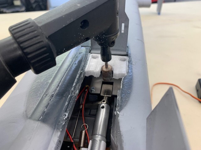
The strut brace had to be slightly ground out to ensure the strut did not rub the brace when rotating for steering. The grinding drum was at lowest speed so as not to melt the plastic brace. Wires had to be routed down and aft to clear the steering arm when retracted. This required cutting a small hole in the gear mount plate and cutting another slot in the foam on the other side. At least now they don't get snagged when steering or after retraction.
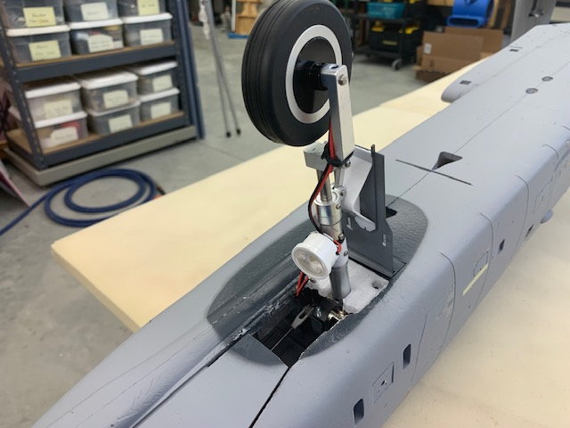
Final look prior to painting the brace. Wires attached to strut with waxed lacing cord
Hot wire cutting a channel for nose gear well wires under the forward equipment tray
Channel allows wires to run under the tray when it is flat on the foam floor
After reading several threads about how the nose gear has a lot of slop and a weak mount I planned on two mods. First is the standard nose strut brace that keeps the strut from back bending forces on rough terrain. I only fly from grass so I thought this would be helpful. I downloaded the brace from Thingiverse and printed it in PETG. Fitting it was a fuss to get the landing light and brakes wires to not get tangled with the steering arm and gear retraction. I also added a single nose wheel brake to comply with AMA rules and to make stopping in the pits easier when taxing back after landing. Brakes are normally not needed when landing my foamies in the grass.
The second mod was to strengthen the nose gear mounting plate. It is plastic and tends to break if bounced. I copied this mod directly from the A-10 threads. It basically backs up the plastic mounting plate with hard wood and uses longer screws to get into the wood backing. First step was to remove the foam from above the right side mounting holes. I used a long knife blade to cut and needle nose pliers to pull out the foam.
Nose gear mounting holes seen from above
Balsa and 1/4" plywood braces fabricated
Braces inserted into the holes above the gear mount
Left side slots are a a little smaller
Braces epoxied into the slots and excess epoxy wiped away
Flush cut saw use to cut the braces flush with the foam floor
Lightly sanded and done
Nose gear installed with #4 x 3/4" socket head screws that reach into the hard wood backing
The strut brace had to be slightly ground out to ensure the strut did not rub the brace when rotating for steering. The grinding drum was at lowest speed so as not to melt the plastic brace. Wires had to be routed down and aft to clear the steering arm when retracted. This required cutting a small hole in the gear mount plate and cutting another slot in the foam on the other side. At least now they don't get snagged when steering or after retraction.
Final look prior to painting the brace. Wires attached to strut with waxed lacing cord
07-26-2022, 05:58 PM
#58
Thread Starter
My Feedback: (20)
Installing front and rear equipment trays
The new slot allows the landing light and brake wires to join the other nose gear wires under the plywood floor.
A small wood block glued to the fuse above the floor holds the floor down and allows removal with just two screws
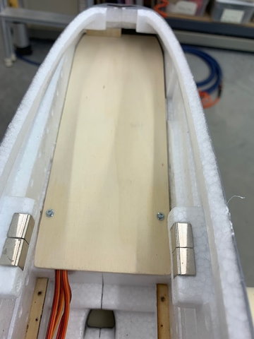
Front floor mounted. A small ply plate was recessed and glued into the foam on the left side and the nose gear mount brace was used on the right side to hold the floor mounting screws.
Front floor covers the nose gear well to prevent grass and dirt from getting slung up and inside. I will paint it later.
Wire leads from nose gear well labeled
Aft equipment tray notched with drum sander to provide clearance for front wires to be routed under the aft tray. Mounting holes drilled using the existing mounting rails already glued into the fuse
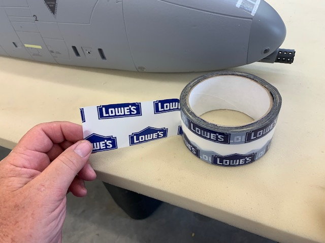
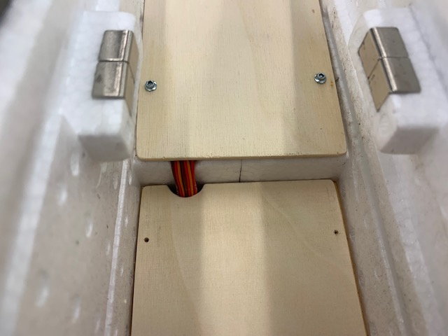
Lowes house wrapping tape for Tyvek house wrap used to hold wires in place running from the aft fuse. It's very sticky, thin, and does not easily tear. Seemed to work very well instead of nylon strapping tape.
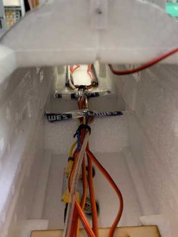
A V shaped notch was cut in the foam wing tube housings above the wing tubes to provide a cable channel for all the wires and tubing from the rear underneath the tank. The house wrapping tape holds the wires in the notches so the fuel tank can rest on top of the foam wing tube housings.
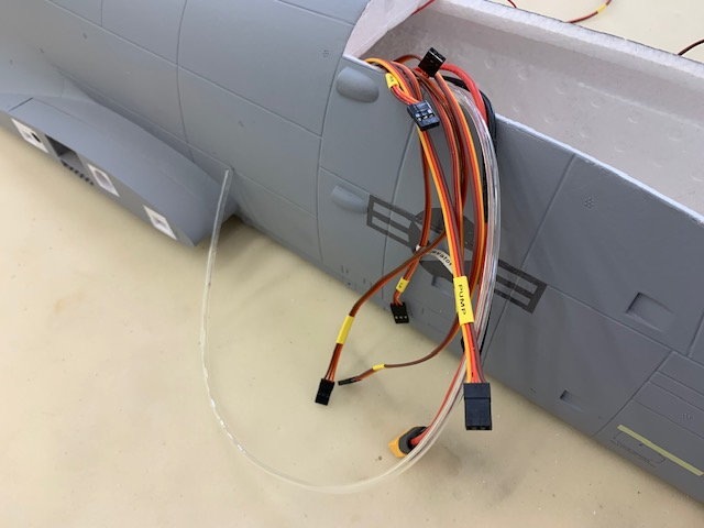
Servo cables from the rear are labeled.
The new slot allows the landing light and brake wires to join the other nose gear wires under the plywood floor.
A small wood block glued to the fuse above the floor holds the floor down and allows removal with just two screws
Front floor mounted. A small ply plate was recessed and glued into the foam on the left side and the nose gear mount brace was used on the right side to hold the floor mounting screws.
Front floor covers the nose gear well to prevent grass and dirt from getting slung up and inside. I will paint it later.
Wire leads from nose gear well labeled
Aft equipment tray notched with drum sander to provide clearance for front wires to be routed under the aft tray. Mounting holes drilled using the existing mounting rails already glued into the fuse
Lowes house wrapping tape for Tyvek house wrap used to hold wires in place running from the aft fuse. It's very sticky, thin, and does not easily tear. Seemed to work very well instead of nylon strapping tape.
A V shaped notch was cut in the foam wing tube housings above the wing tubes to provide a cable channel for all the wires and tubing from the rear underneath the tank. The house wrapping tape holds the wires in the notches so the fuel tank can rest on top of the foam wing tube housings.
Servo cables from the rear are labeled.
Last edited by Viper1GJ; 07-26-2022 at 06:02 PM.
 07-27-2022, 02:21 PM
#60
Thread Starter
My Feedback: (20)
Fuel tank installed
Fuel tank installed using very precise and delicate procedure learned many years ago. I stuffed foam rubber around it in front and back.
The good part is you can see both front and rear ends of the tank so it will be easy to estimate % fuel remaining after flying.
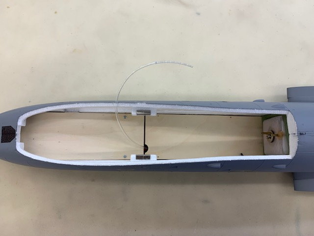
Let the fun begin. Blank canvas ready to get all the needed stuff placed. Hoping to keep most of the wire jungle underneath.
Fuel tank installed using very precise and delicate procedure learned many years ago. I stuffed foam rubber around it in front and back.
The good part is you can see both front and rear ends of the tank so it will be easy to estimate % fuel remaining after flying.
Let the fun begin. Blank canvas ready to get all the needed stuff placed. Hoping to keep most of the wire jungle underneath.
08-20-2022, 04:09 PM
#61
Thread Starter
My Feedback: (20)
Equipment trays ready
It's been about 3 weeks since I got any shop time. House projects caught up on and school started so full time grandkid day care over.
I spent two days trying to figure out how to install everything and started over twice. I finally settled on installing 3/8 x 3/8" poplar rails under the floor to raise the equipment tray up enough to stuff most of the wire jungle and plugs underneath. I finally gave up on trying to get the wing ribbon cables to work without extensions for the ailerons and flaps so I just decided to place the electronics where they would fit and add extensions as necessary. I also made an elevator servo harness that will allow 8 volts to power the two Promodler HV elevator servos and still run everything else on 5.7v
Trays fitted and cut out ready to paint. The small bracket holds the Xicoy fuel pump.
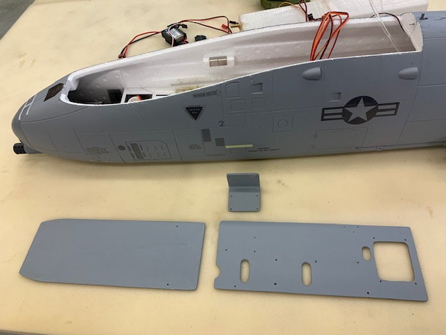
I gave the wood parts a coat of gray paint and a coat of Polycrylic for looks and to keep the light ply from soaking up the inevitable fuel spills so bad. Next steps are to mount, connect, and program all the electronics.
It's been about 3 weeks since I got any shop time. House projects caught up on and school started so full time grandkid day care over.
I spent two days trying to figure out how to install everything and started over twice. I finally settled on installing 3/8 x 3/8" poplar rails under the floor to raise the equipment tray up enough to stuff most of the wire jungle and plugs underneath. I finally gave up on trying to get the wing ribbon cables to work without extensions for the ailerons and flaps so I just decided to place the electronics where they would fit and add extensions as necessary. I also made an elevator servo harness that will allow 8 volts to power the two Promodler HV elevator servos and still run everything else on 5.7v
Trays fitted and cut out ready to paint. The small bracket holds the Xicoy fuel pump.
I gave the wood parts a coat of gray paint and a coat of Polycrylic for looks and to keep the light ply from soaking up the inevitable fuel spills so bad. Next steps are to mount, connect, and program all the electronics.
The following users liked this post:
CNeuhausel (08-21-2022)
08-21-2022, 02:12 PM
#62
Thread Starter
My Feedback: (20)
Equipment tray ready for install
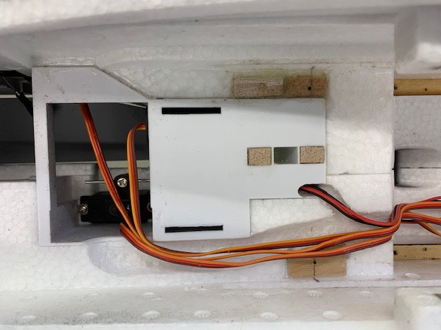
Forward tray installed in fuse. Aft tray holds fuel pump, air trap tank, receiver, and FW electronics board. HV harness for elevator servos labeled and ready for connection
Forward tray installed in fuse. Aft tray holds fuel pump, air trap tank, receiver, and FW electronics board. HV harness for elevator servos labeled and ready for connection
Last edited by Viper1GJ; 08-21-2022 at 02:14 PM.
08-23-2022, 04:18 PM
#63
Thread Starter
My Feedback: (20)
Equipment tray installed
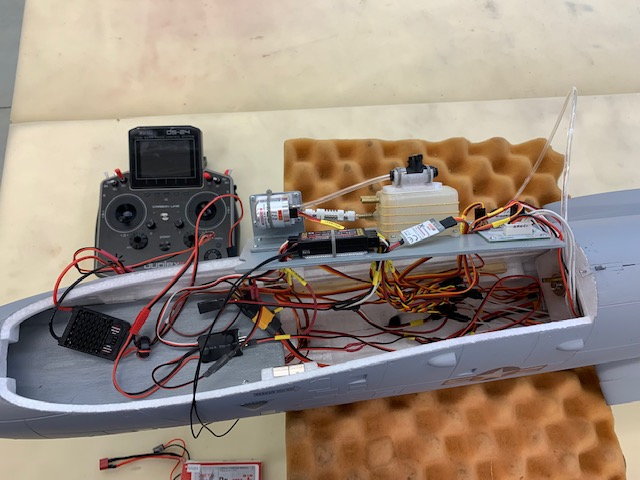
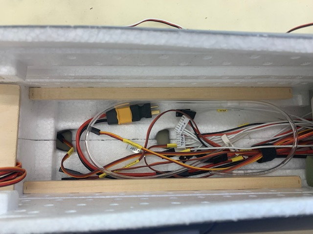
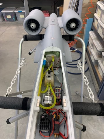
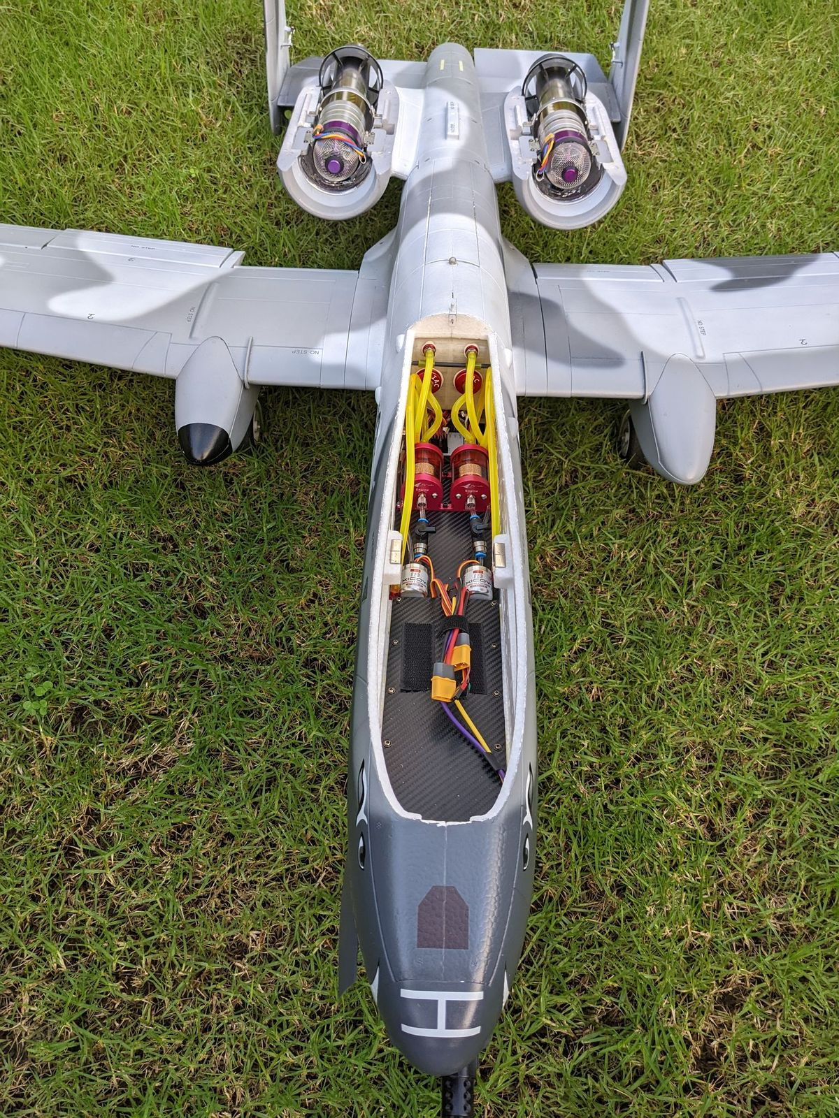
Made good progress today. I got the wire jungle connected and to my surprise everything worked the first time. I installed the wings and the ailerons, flaps, gear, and lights work through the modified ribbon cables. The elevators worked on direct 8v power from the battery. Turbine system and telemetry worked great. I got everything dialed in and programed and removed the wings. This photo shows the tank installed and the wire jungle all connected before stuffing it under the equipment tray.
Wire jungle and brake controller stuffed under the equipment tray and tray screwed down. Next is to install the fuel lines, battery or batteries as necessary for CG, and antennas.
Last edited by Viper1GJ; 08-23-2022 at 04:21 PM.
08-24-2022, 02:48 PM
#64
Thread Starter
My Feedback: (20)
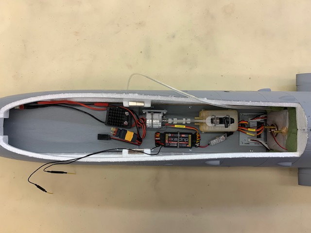
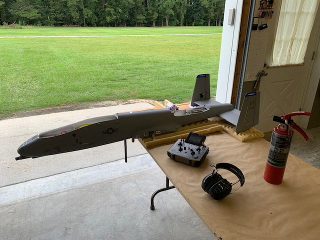
Front end finished
Front end is finished. All fuel plumbing, safety wires, and Rx antennas installed. BEC mounted to front tray. This is the single battery option.
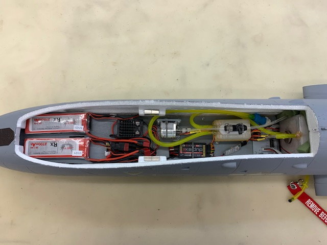
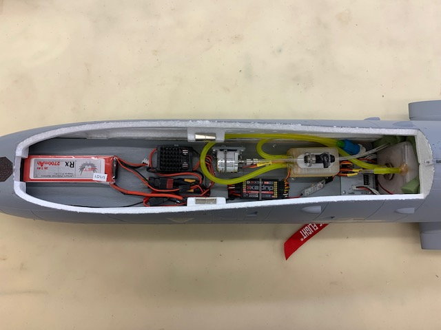
Here is the two battery option. Which one gets used depends on CG requirements. I will not be able to determine CG till I get the engine pods back. I sent them to my friend Keith who is installing freewheeling fans on ball bearing shafts so they will rotate in flight.
It's alive! Everything working now.
Front end is finished. All fuel plumbing, safety wires, and Rx antennas installed. BEC mounted to front tray. This is the single battery option.
Here is the two battery option. Which one gets used depends on CG requirements. I will not be able to determine CG till I get the engine pods back. I sent them to my friend Keith who is installing freewheeling fans on ball bearing shafts so they will rotate in flight.
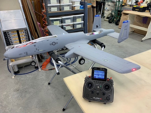
It's alive! Everything working now.
08-26-2022, 05:21 PM
#65
Thread Starter
My Feedback: (20)
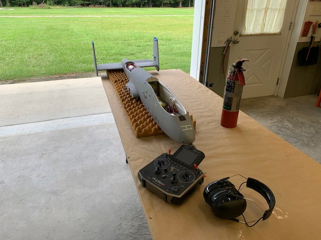
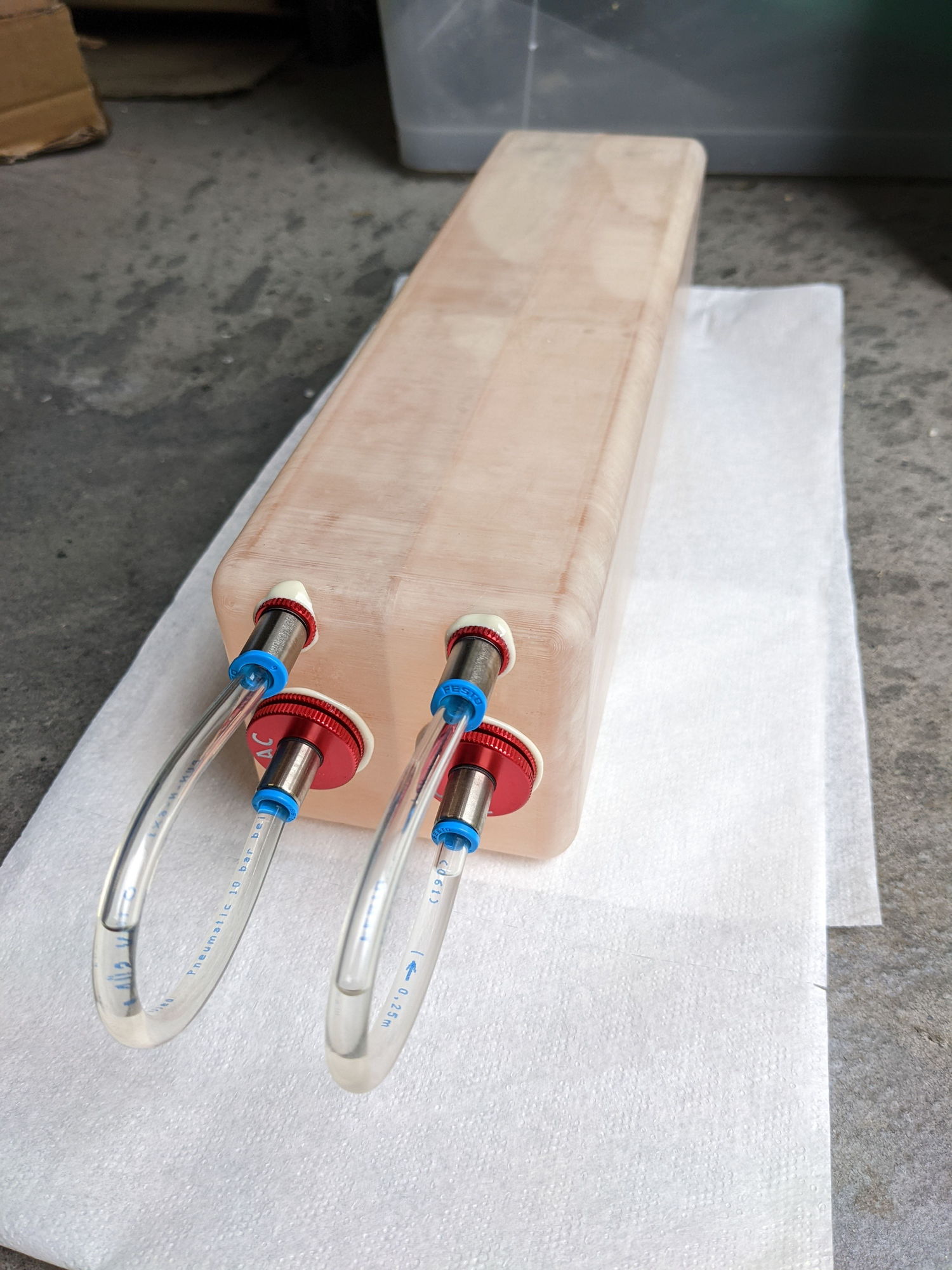
New turbine test runs
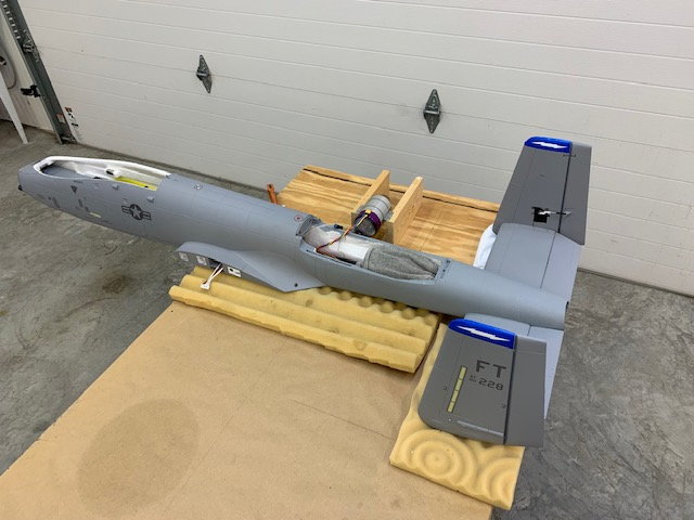
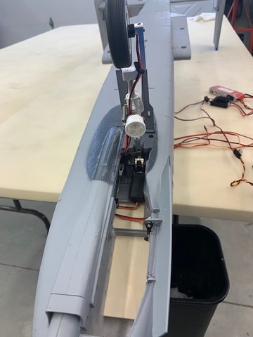
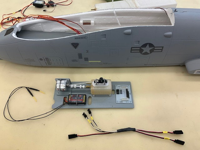
I always do first starts and runs on a new turbine on a test stand to verify the factory default settings will not burn down my new jet. Especially important on this one since there are small clearances and it is all foam with a plastic bell mouth on my first homemade pipe. I like to use the same plumbing and tank set up that is in the jet if possible. In this case it was easy to just run the fuel tubing and wiring harness over the side to the test stand.
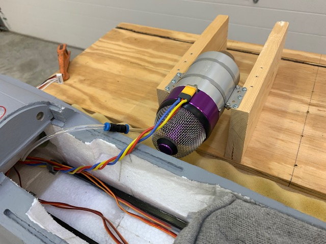
Close up of test stand setup
Two starts and test runs and the new X45 was perfect. After the last shutdown I noticed a fuel puddle on the floor under the nose. The equipment tray was soaked and fuel was all over the air trap tank and festo shut off valve. I did not expect that. AARRGGHH!!!
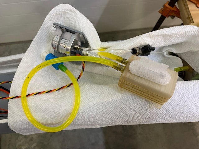
I took out the fuel pump, air trap tank, shut off valve and dried everything out. Glad I painted the tray now! I discovered while running the pump test that air bubbles were coming out of the shut off valve but none were going in. I had failed to properly seat the 4mm tubing into the push to connect valve on the exit side of the of the valve. Under pump pressure fuel was leaking and running down the air trap tank and on the tray and out the nose gear door to the floor. So it was an easy fix. I made two more test runs with a paper towel under the fuel system at full pump pressure and not a drop from the system. System was reassembled for next tests.
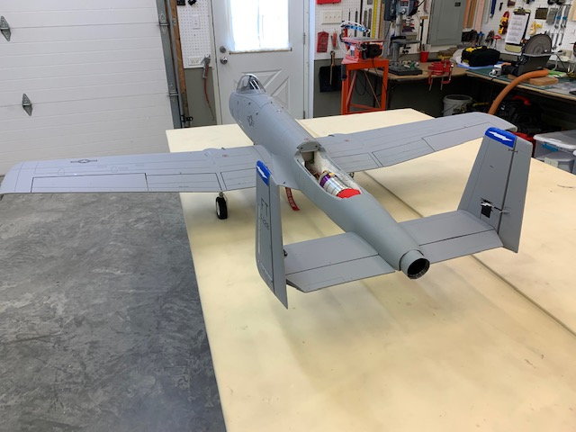
BVM Heat Shield coating painted on the bare foam around the turbine area and back in the tunnel to where the double wall pipe starts. After the coating was dry the turbine and pipe were installed.
The next two test starts and runs were made with the turbine installed but with the engine pod hatch off. Extended run times were made at idle and full power to test for any possible heat damage to the foam or the pipe.
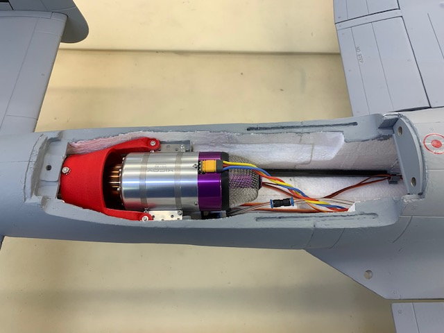
No heat damage noted in turbine area
Turbine was removed and pipe inspected. No indications of any heat damage anywhere...and no leaks!
 .
.
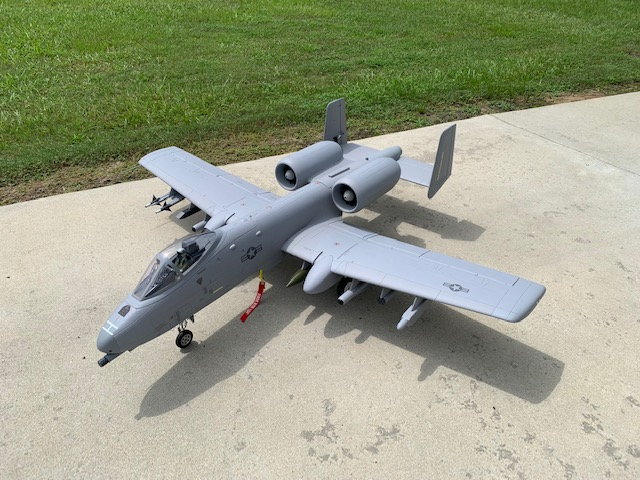
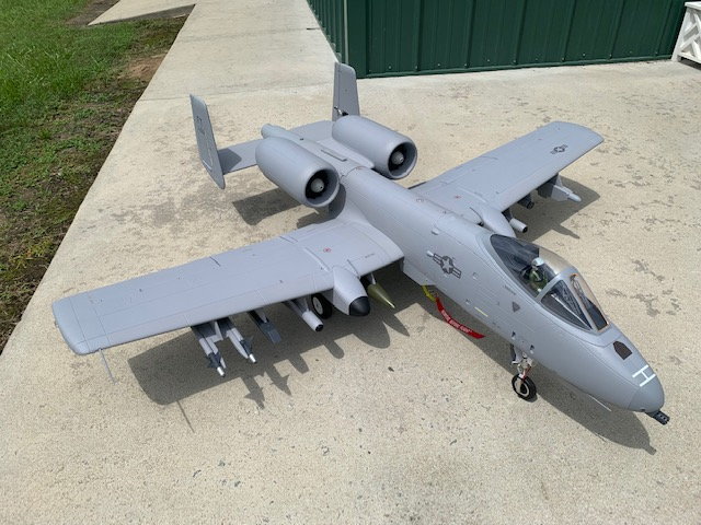
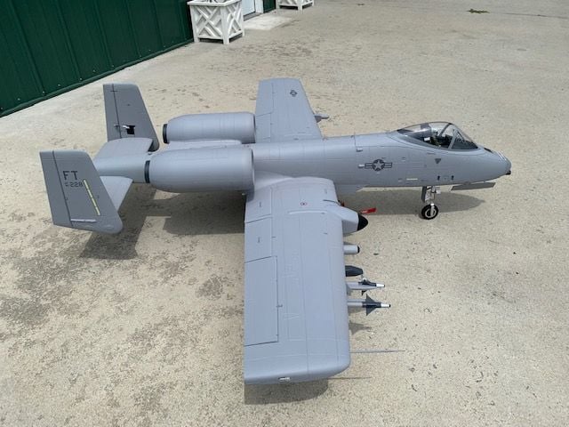
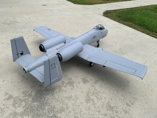
Wings installed for radio, telemetry, and gyro programming. Everything working good so far.
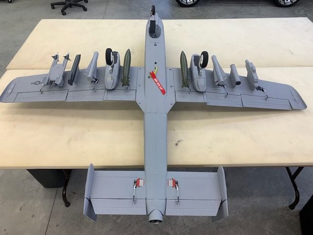
All the Freewing eye candy installed on he wings
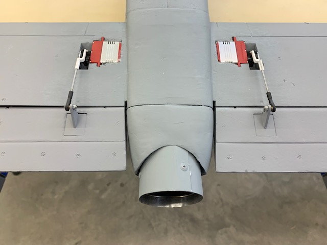
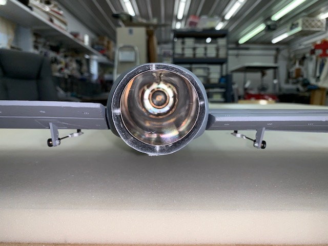
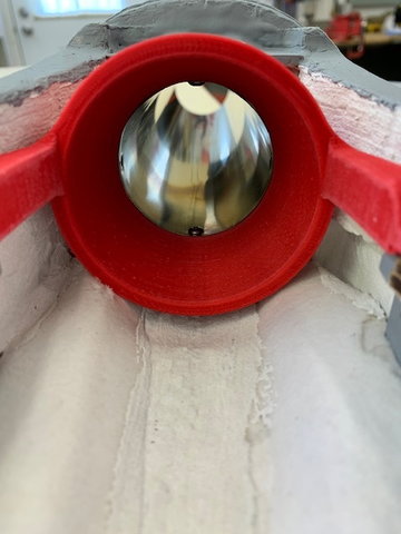
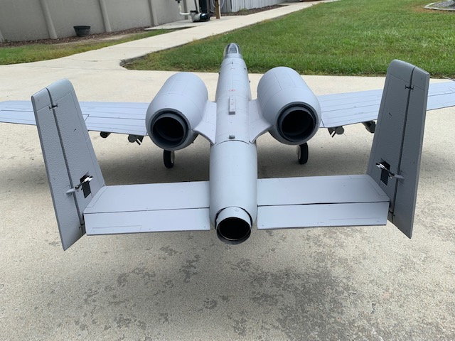
Close up of pipe exit on bottom
It took both batteries in the nose and the canopy to keep the jet from sitting on the tail. I anticipate I will need some additional nose weight after the engine pods are installed. My engine pods with windmilling fans should arrive next week. Then final turbine runs with hatch on and CG checks can be completed.
I always do first starts and runs on a new turbine on a test stand to verify the factory default settings will not burn down my new jet. Especially important on this one since there are small clearances and it is all foam with a plastic bell mouth on my first homemade pipe. I like to use the same plumbing and tank set up that is in the jet if possible. In this case it was easy to just run the fuel tubing and wiring harness over the side to the test stand.
Close up of test stand setup
Two starts and test runs and the new X45 was perfect. After the last shutdown I noticed a fuel puddle on the floor under the nose. The equipment tray was soaked and fuel was all over the air trap tank and festo shut off valve. I did not expect that. AARRGGHH!!!
I took out the fuel pump, air trap tank, shut off valve and dried everything out. Glad I painted the tray now! I discovered while running the pump test that air bubbles were coming out of the shut off valve but none were going in. I had failed to properly seat the 4mm tubing into the push to connect valve on the exit side of the of the valve. Under pump pressure fuel was leaking and running down the air trap tank and on the tray and out the nose gear door to the floor. So it was an easy fix. I made two more test runs with a paper towel under the fuel system at full pump pressure and not a drop from the system. System was reassembled for next tests.
BVM Heat Shield coating painted on the bare foam around the turbine area and back in the tunnel to where the double wall pipe starts. After the coating was dry the turbine and pipe were installed.
The next two test starts and runs were made with the turbine installed but with the engine pod hatch off. Extended run times were made at idle and full power to test for any possible heat damage to the foam or the pipe.
No heat damage noted in turbine area
Turbine was removed and pipe inspected. No indications of any heat damage anywhere...and no leaks!
. Wings installed for radio, telemetry, and gyro programming. Everything working good so far.
All the Freewing eye candy installed on he wings
Close up of pipe exit on bottom
It took both batteries in the nose and the canopy to keep the jet from sitting on the tail. I anticipate I will need some additional nose weight after the engine pods are installed. My engine pods with windmilling fans should arrive next week. Then final turbine runs with hatch on and CG checks can be completed.
The following users liked this post:
Thoemse (08-29-2022)
08-31-2022, 04:43 PM
#66
Thread Starter
My Feedback: (20)
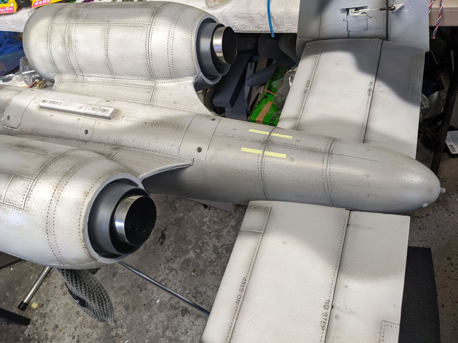
Engine Pods Arrived
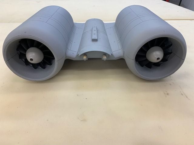
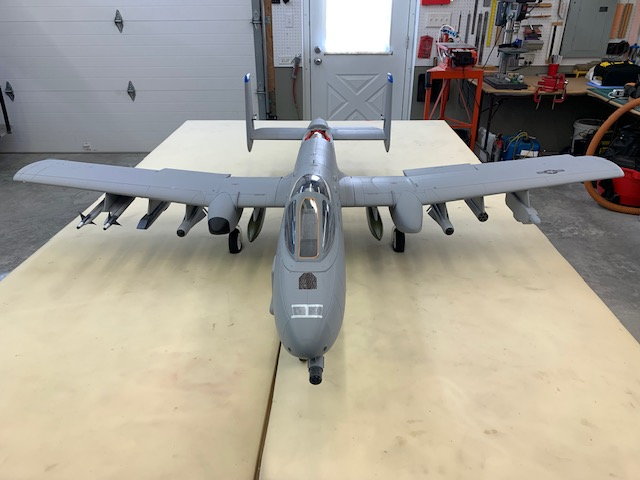
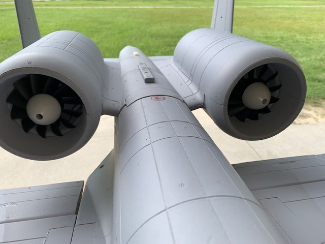
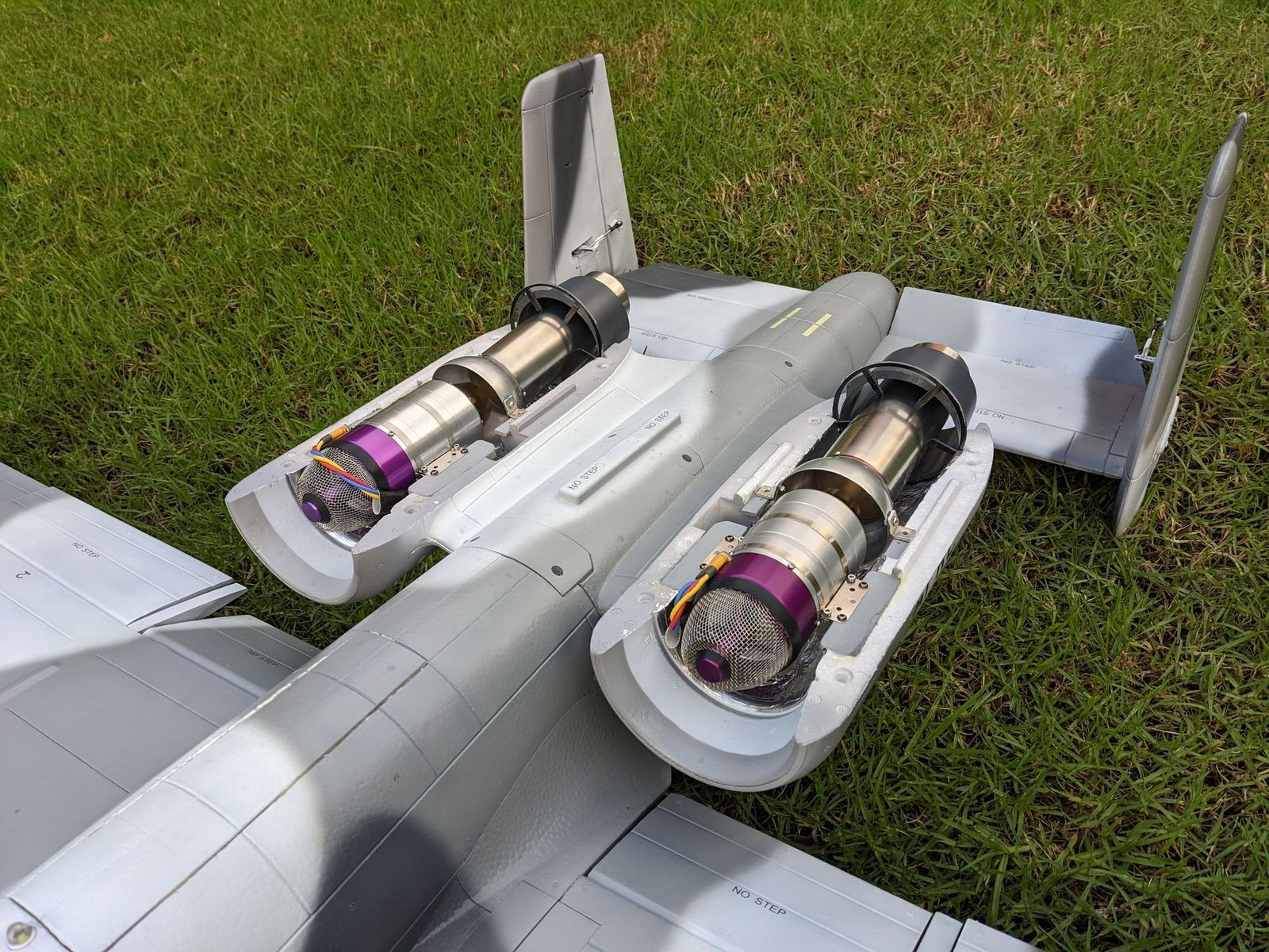
The engine pods arrived today after a couple of weeks with my friend Keith. Keith installed two free spinning wind milling fans in the engine nacelles. They look cool and work really well.
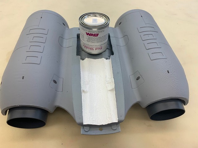
BVM heat shield coating painted on inside of hatch above turbine area
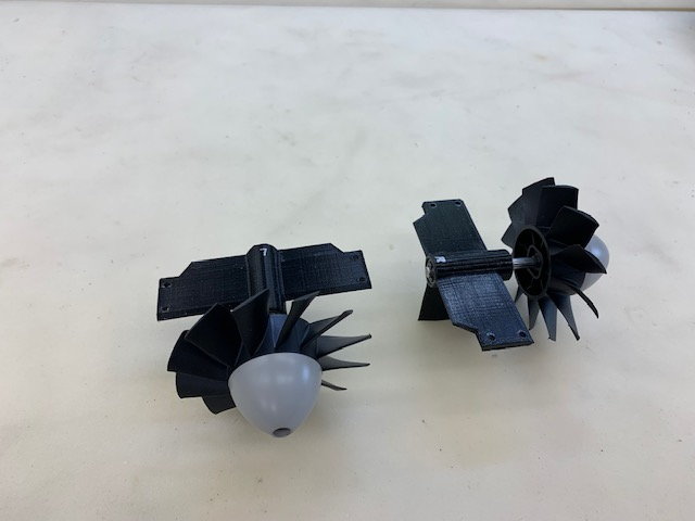
Keith designed and 3D printed the fan holders. The shaft is supported by front and rear ball bearings which allow the fans to turn freely.
The fan holders are mounted to existing EDF plywood mounts and an additional plywood footer at the bottom of the nacelle.
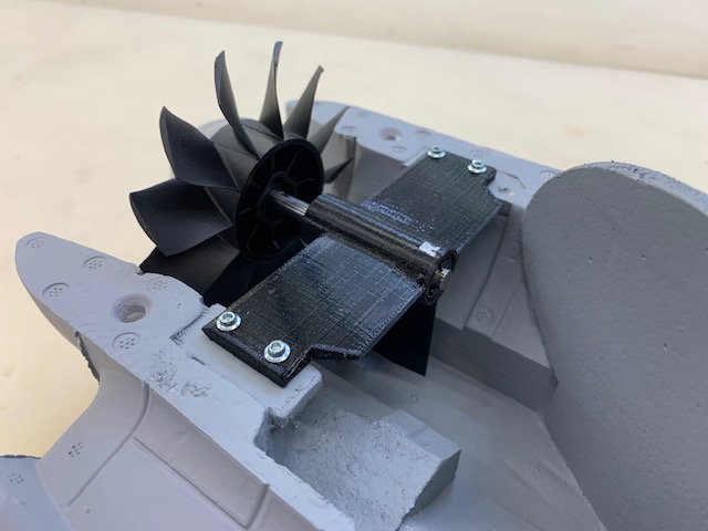
The leading edge of the fan holder has an airfoiled shape.
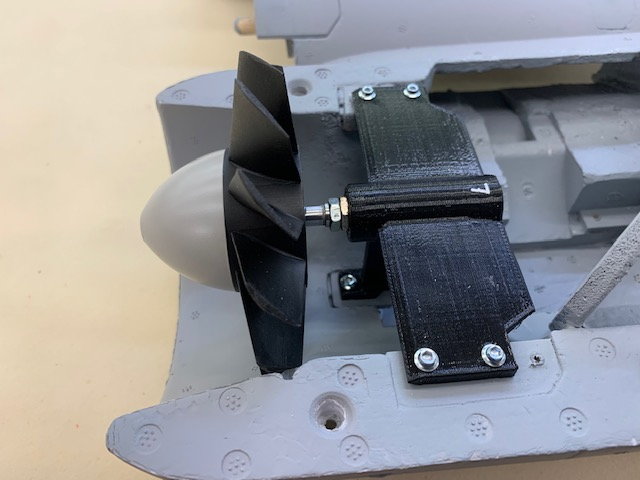
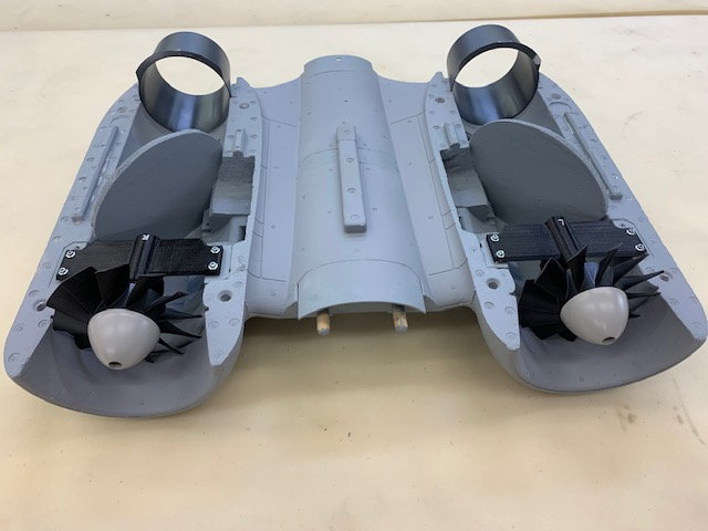
The bottom plywood footer can be seen here
Many thanks to my friend Keith for all his efforts in design, 3D printing, and use of all his spare EDF parts. Engine pods look much better now.
CG setting and turbine test runs planned next. Hopefully the foam around the turbine and pipe will not melt and the fans will rotate when the turbine air is pulled through the front of the engine nacelles, Maybe they will spin at idle thrust. We will see.
The engine pods arrived today after a couple of weeks with my friend Keith. Keith installed two free spinning wind milling fans in the engine nacelles. They look cool and work really well.
BVM heat shield coating painted on inside of hatch above turbine area
Keith designed and 3D printed the fan holders. The shaft is supported by front and rear ball bearings which allow the fans to turn freely.
The fan holders are mounted to existing EDF plywood mounts and an additional plywood footer at the bottom of the nacelle.
The leading edge of the fan holder has an airfoiled shape.
The bottom plywood footer can be seen here
Many thanks to my friend Keith for all his efforts in design, 3D printing, and use of all his spare EDF parts. Engine pods look much better now.
CG setting and turbine test runs planned next. Hopefully the foam around the turbine and pipe will not melt and the fans will rotate when the turbine air is pulled through the front of the engine nacelles, Maybe they will spin at idle thrust. We will see.
The following users liked this post:
T22 Warrior (10-20-2022)
09-01-2022, 12:17 PM
#67
Thread Starter
My Feedback: (20)
Fully enclosed turbine tests
Three starts and runs completed. Extended runs at idle and max power made to check for abnormal turbine ops and any heat damage. No increase in turbine EGT or pump values were noted. There were no signs of foam damage from heat even though the foam was warm inside the hatch. I think the best technique will be starting with the hatch off and removing hatch prior to shut down to give max cooling to foam surfaces around the turbine even though I did two cool down cycles with the hatch on with no problems.
The coolest part was watching the fans spool up when the turbine started up. The fans are turning faster than I expected so better not get a finger in there. Keith did an outstanding job engineering and making the fans work. I got a video on the third start. Enjoy!
Last edited by Viper1GJ; 09-01-2022 at 12:21 PM.
The following 2 users liked this post by Viper1GJ:
Afterburners (09-02-2022),
grbaker (09-01-2022)
The following users liked this post:
Viper1GJ (09-01-2022)
09-02-2022, 04:35 PM
#69
Thread Starter
My Feedback: (20)
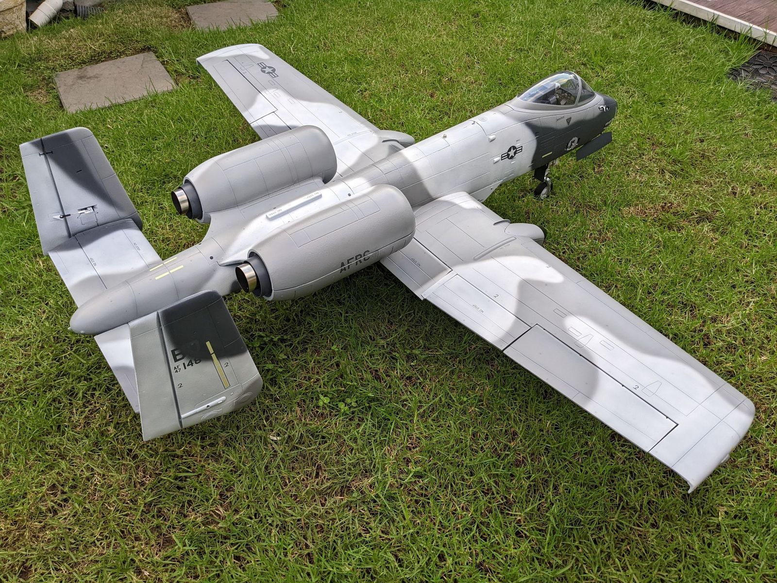
Checking CG and weight
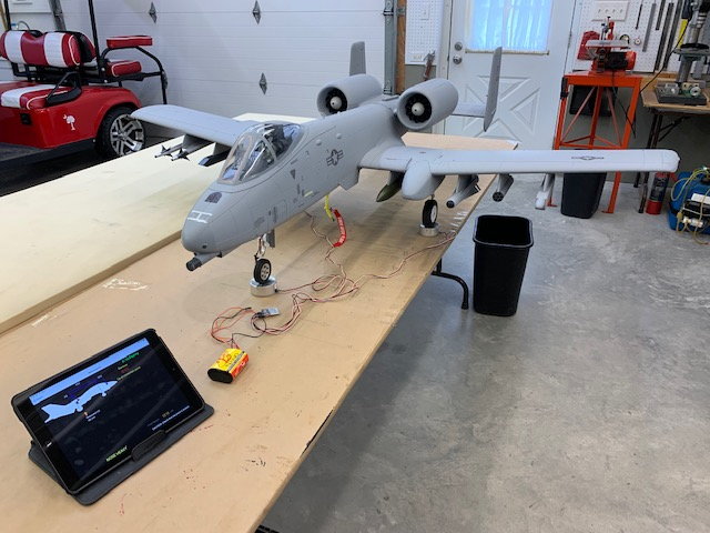
Jet was placed on the Xicoy CG machine wtth Blue Tooth to iPad. Empty weight CG was set by adding nose weight. Fuel was then added and CG checked at all levels from empty to full. I found that the CG only changed 1mm toward the nose with full fuel so I was very pleased with the tank placement.
I'm using 90mm behind the wing leading edge which is 43mm ahead of the main landing gear for the CG. This is 12mm aft of the book recommended CG of 78mm. 78mm has been determined to be way nose heavy and results in the kangaroo hop landing and broken nose gears. Weight was added to the large cavity in the forward nose gear well to get the proper CG. I had to add 15oz of lead to the nose to get the desired CG. At first I was crushed but then I remembered I do not have the two 6S LiPo batteries loaded in the front end that the EDF requires. Research of existing internet threads show my A-10 to be right where other turbine conversions are and even lighter than some of the EDFs out there.

Empty weight is 13 lbs with the desired CG.
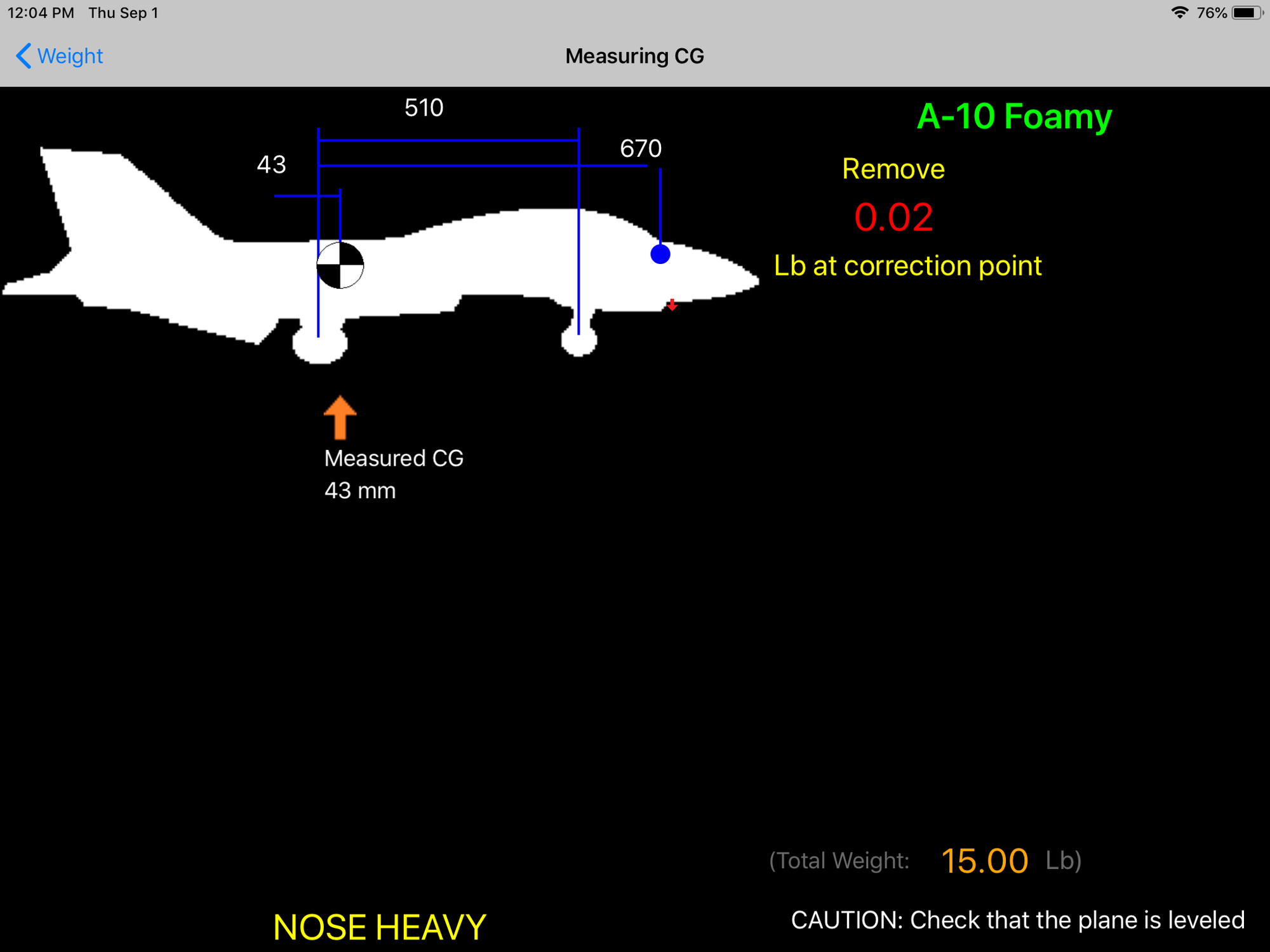
Takeoff weight is 15 lbs. The CG is the same as empty weight. The take off weight is slightly higher than the EDF but landing weight will be slightly lighter. Overall I'm satisfied.
Jet was placed on the Xicoy CG machine wtth Blue Tooth to iPad. Empty weight CG was set by adding nose weight. Fuel was then added and CG checked at all levels from empty to full. I found that the CG only changed 1mm toward the nose with full fuel so I was very pleased with the tank placement.
I'm using 90mm behind the wing leading edge which is 43mm ahead of the main landing gear for the CG. This is 12mm aft of the book recommended CG of 78mm. 78mm has been determined to be way nose heavy and results in the kangaroo hop landing and broken nose gears. Weight was added to the large cavity in the forward nose gear well to get the proper CG. I had to add 15oz of lead to the nose to get the desired CG. At first I was crushed but then I remembered I do not have the two 6S LiPo batteries loaded in the front end that the EDF requires. Research of existing internet threads show my A-10 to be right where other turbine conversions are and even lighter than some of the EDFs out there.
Empty weight is 13 lbs with the desired CG.
Takeoff weight is 15 lbs. The CG is the same as empty weight. The take off weight is slightly higher than the EDF but landing weight will be slightly lighter. Overall I'm satisfied.

The following users liked this post:
Viper1GJ (09-03-2022)
09-02-2022, 05:22 PM
#72

Looking forward to your maiden and should be a real floater.
I did mine the conventional way and only took a weekend to do. 3D printed tank also but split each side 850ml per turbine with a baffle and i think was a bit over 7kg full fuelled.
I did mine the conventional way and only took a weekend to do. 3D printed tank also but split each side 850ml per turbine with a baffle and i think was a bit over 7kg full fuelled.
The following users liked this post:
Viper1GJ (09-03-2022)
09-02-2022, 09:56 PM
#74
Yeah it's definitely too much for a foamie, but this was not the aim from the start.
I have other foamie conversions and 2 X45's and the electric in the A-10 was starting to get a bit boring so it was just a quick project.
I have other foamie conversions and 2 X45's and the electric in the A-10 was starting to get a bit boring so it was just a quick project.
Last edited by gixer47; 09-02-2022 at 11:48 PM.
The following users liked this post:
Viper1GJ (09-03-2022)