


Turbine Conversion Of 80mm Freewing A-10 To Single X-45 Turbine
 07-04-2022, 02:45 PM
#1

Thread Starter
My Feedback: (20)
I've been looking at the idea of converting a Freewing 80mm A-10 EDF to a single turbine for couple of years. I recently sold my last giant scale jet and am looking forward to playing with smaller jets that I can more easily move around and don't cost so much. I recently found a FW A-10 PNP NIB for a great price and jumped on it. Inspiration and techniques came from several sources. Thanks to my friend Keith for advice and encouragement with 3D CAD and pipe fabrication, Michael B. for actually doing one, flying it, and posting his photos on FB, and Paul A for sharing his foamy conversion ideas and expertise on YouTube videos. I shamelessly used and copied their ideas plus added a few of my own.
The jet is still a work in progress but the hard parts are done. Photos below are to show current progress and overall idea. After getting the jet out of the box and studying the rear end layout I took the approach to just fit the turbine and pipe in the tail where I thought it needed to go and then rebuild the airplane around it as needed. This required removing the square carbon tube backbone of the EDF fuse, gutting all the foam from the center of the forward and aft fuse, and removing the center section of both stab spars.
This is the most complex conversion I have done so far. Clearly, doing a twin turbine conversion would be lots easier, but where's the challenge with that? Plus the cost is double and you only get one airplane instead of two. As I was cutting the stab spars I thought, this is not for the "faint at heart" if you are not able to do some scratch building to put the airframe back together. Anyway, this is for your info only and will be a step by step of how I did it. As of now, it has not been started or flown. Results are TBD. Comments and recommendations are welcome as always.
Thanks,
Gary
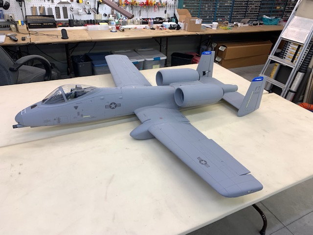
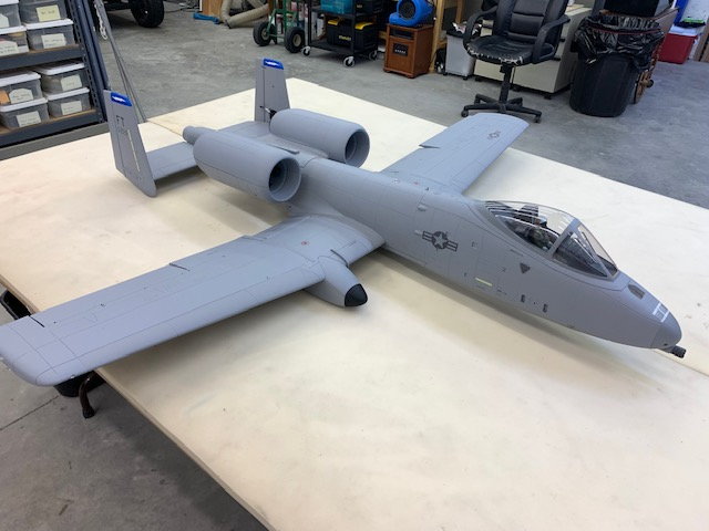
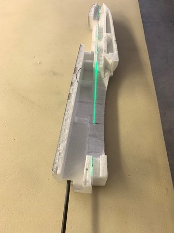
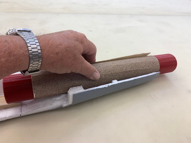
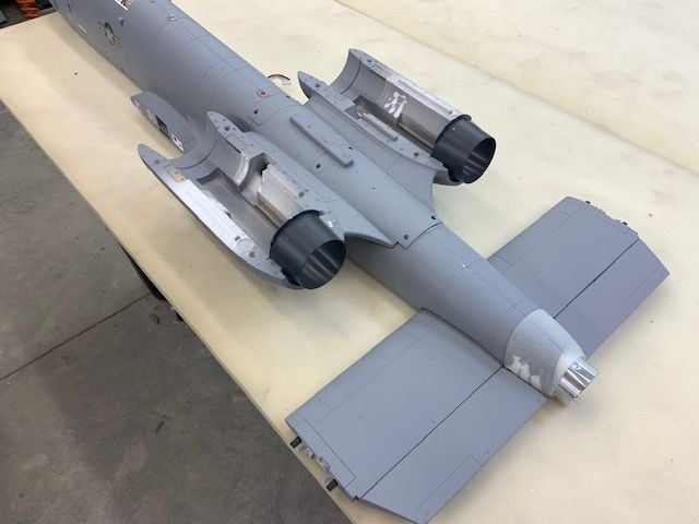
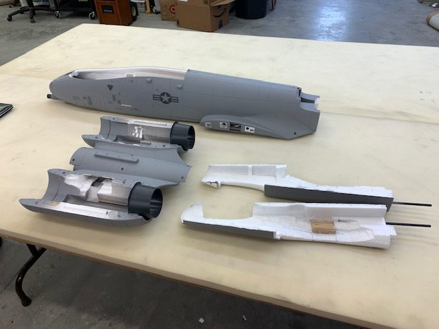
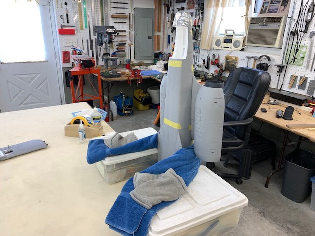
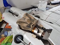
After working mostly on the rear end this is the first time I put the wings on just to see how it looked overall. Pipe is barely visible from this angle
Pipe hidden from here
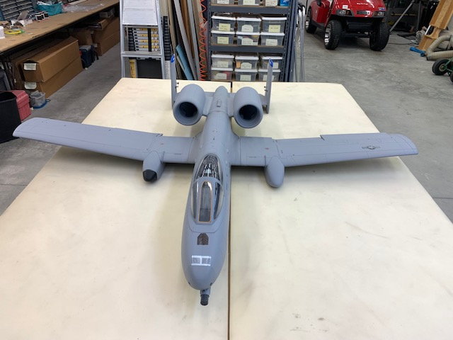
Barely visible here. All turbine air enters through the scale engine nacelle intakes
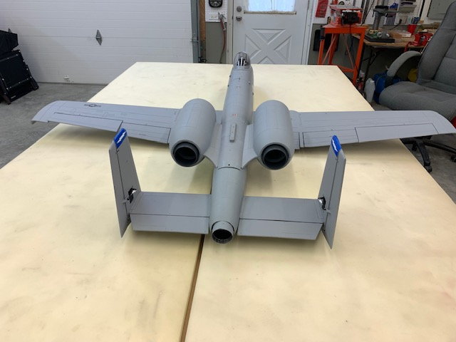
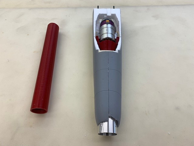
Not too bad from the rear
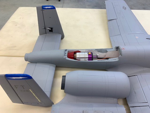
Engine nacelle mount is the turbine hatch and turbine air all comes through the scale nacelle intakes and is ducted to the turbine inside the nacelle pylons.
The jet is still a work in progress but the hard parts are done. Photos below are to show current progress and overall idea. After getting the jet out of the box and studying the rear end layout I took the approach to just fit the turbine and pipe in the tail where I thought it needed to go and then rebuild the airplane around it as needed. This required removing the square carbon tube backbone of the EDF fuse, gutting all the foam from the center of the forward and aft fuse, and removing the center section of both stab spars.
This is the most complex conversion I have done so far. Clearly, doing a twin turbine conversion would be lots easier, but where's the challenge with that? Plus the cost is double and you only get one airplane instead of two. As I was cutting the stab spars I thought, this is not for the "faint at heart" if you are not able to do some scratch building to put the airframe back together. Anyway, this is for your info only and will be a step by step of how I did it. As of now, it has not been started or flown. Results are TBD. Comments and recommendations are welcome as always.
Thanks,
Gary
After working mostly on the rear end this is the first time I put the wings on just to see how it looked overall. Pipe is barely visible from this angle
Pipe hidden from here
Barely visible here. All turbine air enters through the scale engine nacelle intakes
Not too bad from the rear
Engine nacelle mount is the turbine hatch and turbine air all comes through the scale nacelle intakes and is ducted to the turbine inside the nacelle pylons.
Last edited by Viper1GJ; 07-05-2022 at 05:33 AM.

The following 2 users liked this post by Viper1GJ:
Afterburners (09-02-2022),
drfred58809 (07-04-2022)
07-04-2022, 03:12 PM
#2
Thread Starter
My Feedback: (20)
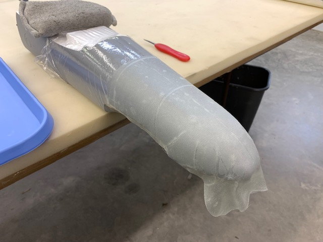
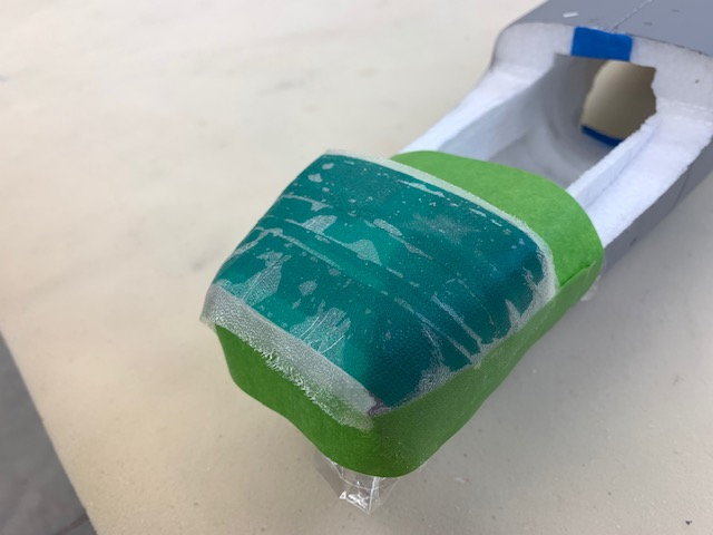
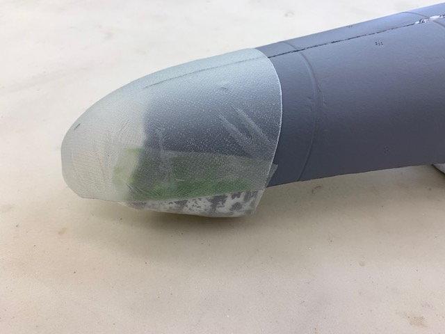
The first step was to make a fiberglass tail cone that I could later cut to fit around the pipe to make a smooth exit hole from the fuse. I used Paul A's technique of using the foam fuse part as a mold and wrap as a release. Water is sprayed on the fuse and plastic wrap stretched over the part and taped in place.
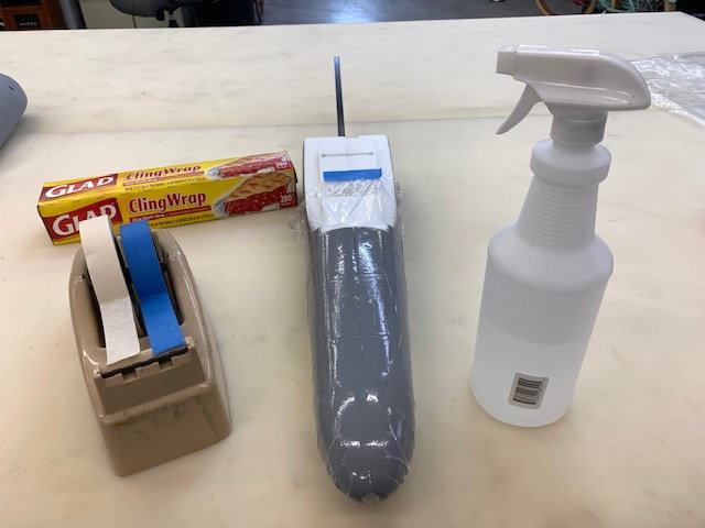
I found that the plastic would not stretch around compound curves very well but it did not affect the final part since it was cut mostly above the wrinkles.
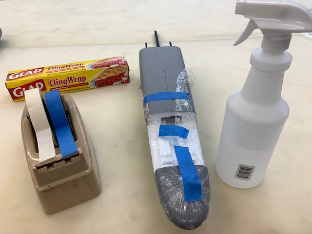
Plastic wrap pulled and taped on bottom. A light coat of wax was rubbed over the plastic wrap
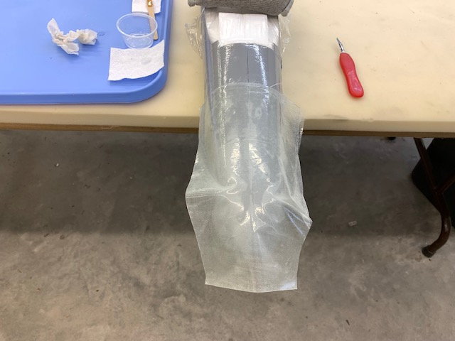
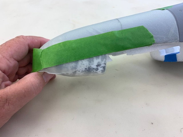
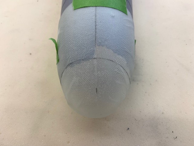
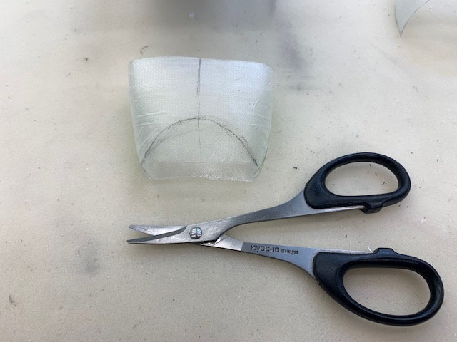
I used Paul A's technique of using two layers of 3 oz. cloth on 45 degree bias wetted out between plastic sheets. Then the pattern was cut out and bottom layer of plastic removed. The glass with top layer of plastic still on is transferred to the the fuse mold.
Top layer of plastic removed and glass stretched around the fuse mold
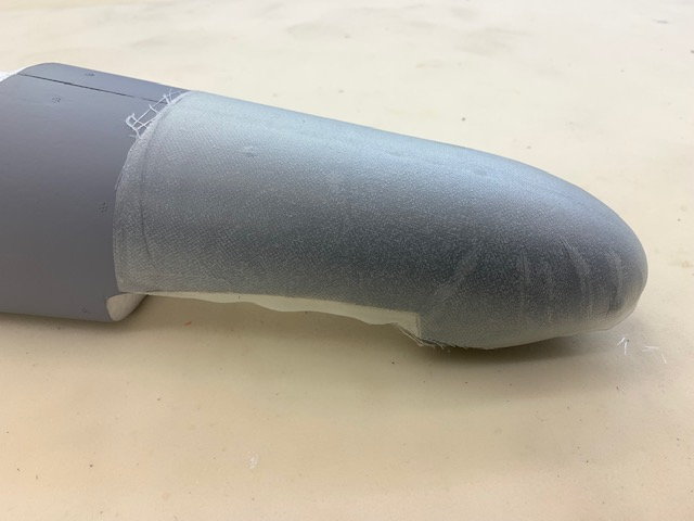
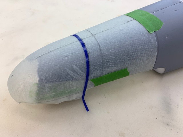
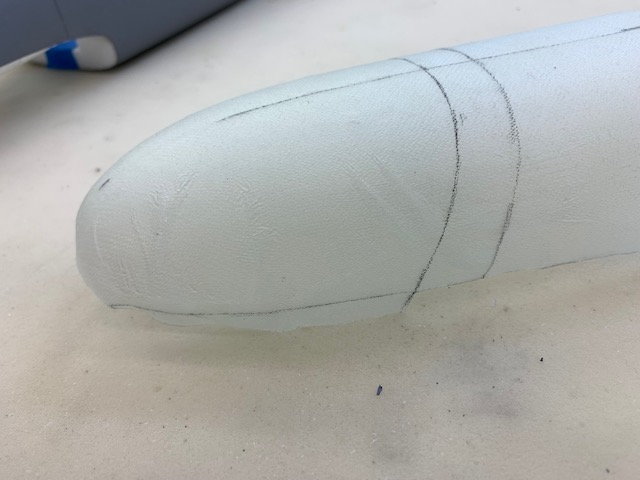
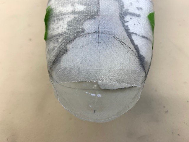
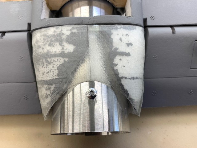
Epoxy cured and glass trimmed
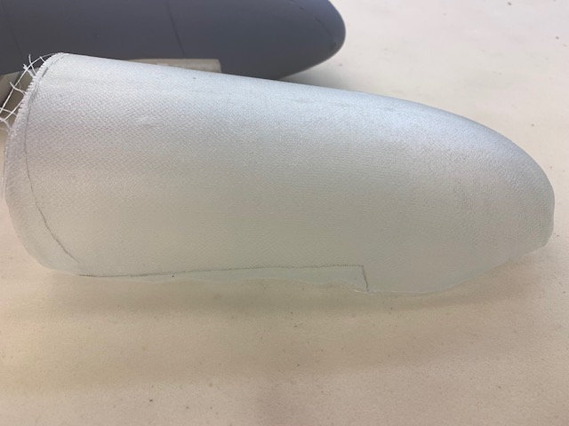
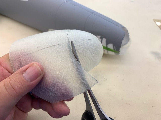
Fuse lines traced and glass part pulled off mold. Not bad for my first try. Later most of the wrinkle parts were cut away and or easily filled.
The gross error I made here was forgetting to turn the fuse over and make a part for the bottom of the rear fuse. I got in a hurry to start cutting foam and I had to make it later after I had already cut out the foam for the pipe exit and it was much difficult. Also if I were to try it again I would probably use silicon or vinyl tape instead of plastic wrap for the compound curve areas. The plastic wrap just did not work well on the compound curves.
I found that the plastic would not stretch around compound curves very well but it did not affect the final part since it was cut mostly above the wrinkles.
Plastic wrap pulled and taped on bottom. A light coat of wax was rubbed over the plastic wrap
I used Paul A's technique of using two layers of 3 oz. cloth on 45 degree bias wetted out between plastic sheets. Then the pattern was cut out and bottom layer of plastic removed. The glass with top layer of plastic still on is transferred to the the fuse mold.
Top layer of plastic removed and glass stretched around the fuse mold
Epoxy cured and glass trimmed
Fuse lines traced and glass part pulled off mold. Not bad for my first try. Later most of the wrinkle parts were cut away and or easily filled.
The gross error I made here was forgetting to turn the fuse over and make a part for the bottom of the rear fuse. I got in a hurry to start cutting foam and I had to make it later after I had already cut out the foam for the pipe exit and it was much difficult. Also if I were to try it again I would probably use silicon or vinyl tape instead of plastic wrap for the compound curve areas. The plastic wrap just did not work well on the compound curves.
The following users liked this post:
drfred58809 (07-04-2022)
07-04-2022, 03:47 PM
#3
Thread Starter
My Feedback: (20)
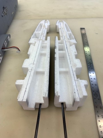
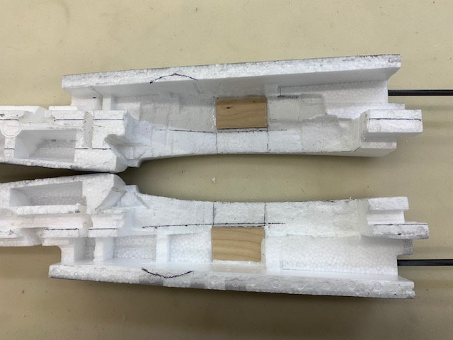
Splitting the rear fuse
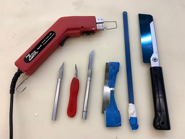
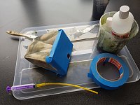
Foam cutting tools used
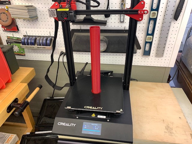
I asked Keith to send me a file to 3D print a 52mm sanding drum mandrel. I anticipated the need to sand the aft fuse to create the channel for the turbine pipe. I printed it from PLA and it was very useful for several tasks in the build.
Initial concept of turbine placement
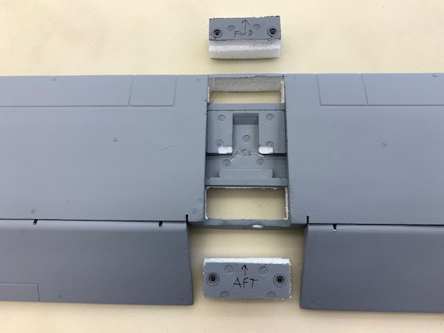
Started using hot wire cutter to slice off foam parts but then decided to split the aft fuse in half
Razor saw initially used to cut through FW plastic engine pod mounts
Switched to hack saw blade for deeper cuts
Cutting aft engine pod mount in half
Cutting forward plastic stab mounts
Cutting aft stab mount
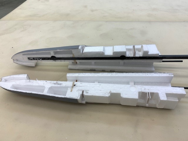
Aft fuse split open showing carbon square tube backbone. I was surprised to see how far back it went.
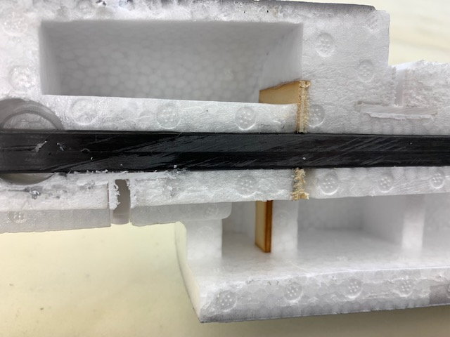
Hidden ply former to hold the square carbon tube in place
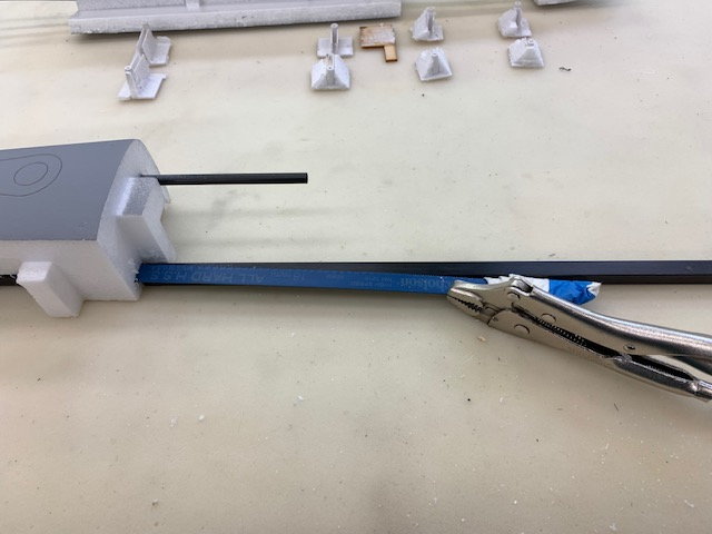
Hack saw blade in vice grips to cut out the square tube
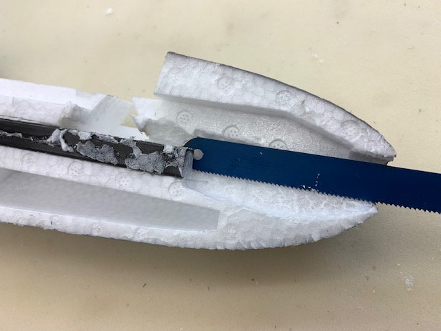
Slicing out the aft end of the tube
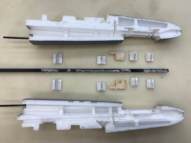
Plastic and wood parts removed from the aft fuse. This where I began to wonder if this idea was going to work since there was not much foam in the rear fuse
I drew in my planned thrust lines from the center of the rear tail cone parallel to the carbon tube. As it turned out the planned thrust line was the top side of the carbon tube slot and closely aligned with a fuse panel line just above the main wing chord that went all the way to the nose. I figured since the new turbine thurst line was nearly at the wing line this "zero degree" thrust line would probably be OK. Like all the other foamy conversions I've done its all "TLAR" anyway.
Foam cutting tools used
I asked Keith to send me a file to 3D print a 52mm sanding drum mandrel. I anticipated the need to sand the aft fuse to create the channel for the turbine pipe. I printed it from PLA and it was very useful for several tasks in the build.
Initial concept of turbine placement
Started using hot wire cutter to slice off foam parts but then decided to split the aft fuse in half
Razor saw initially used to cut through FW plastic engine pod mounts
Switched to hack saw blade for deeper cuts
Cutting aft engine pod mount in half
Cutting forward plastic stab mounts
Cutting aft stab mount
Aft fuse split open showing carbon square tube backbone. I was surprised to see how far back it went.
Hidden ply former to hold the square carbon tube in place
Hack saw blade in vice grips to cut out the square tube
Slicing out the aft end of the tube
Plastic and wood parts removed from the aft fuse. This where I began to wonder if this idea was going to work since there was not much foam in the rear fuse
I drew in my planned thrust lines from the center of the rear tail cone parallel to the carbon tube. As it turned out the planned thrust line was the top side of the carbon tube slot and closely aligned with a fuse panel line just above the main wing chord that went all the way to the nose. I figured since the new turbine thurst line was nearly at the wing line this "zero degree" thrust line would probably be OK. Like all the other foamy conversions I've done its all "TLAR" anyway.
Last edited by Viper1GJ; 07-04-2022 at 05:45 PM.
The following users liked this post:
drfred58809 (07-04-2022)
07-04-2022, 04:10 PM
#4
Thread Starter
My Feedback: (20)
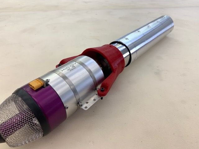
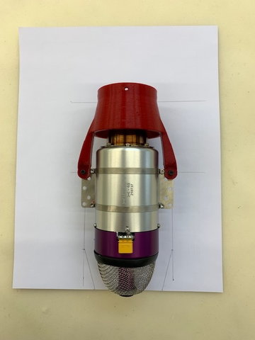
Pipe bell mouth
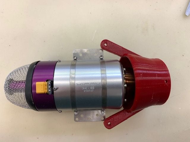
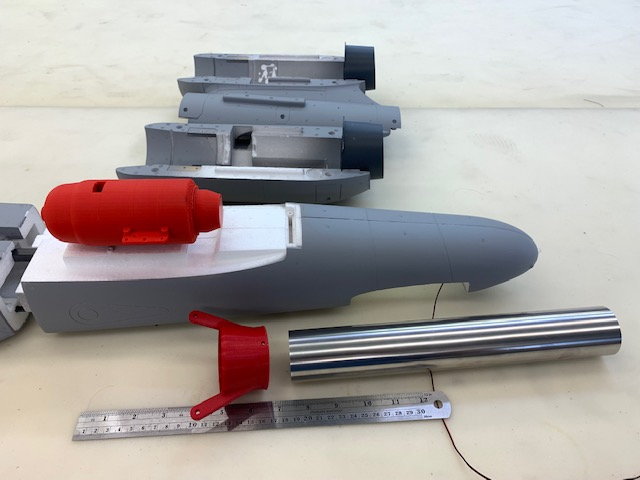
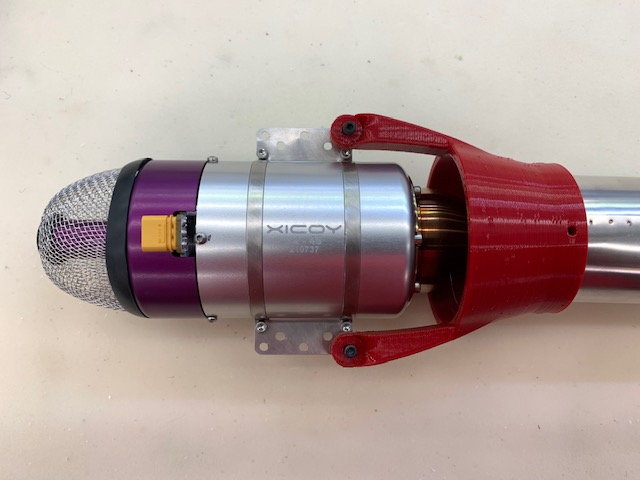
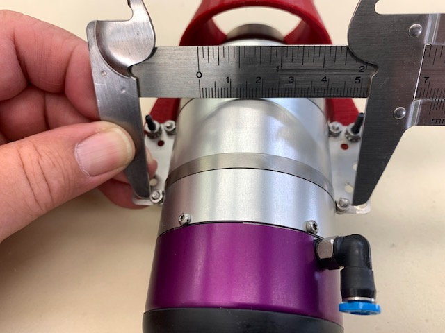
The plan is to use one of Keith's 3D printed pipe bell mounts from high temp heat treated PLA. Keith has been using these pipe cones for a couple of years with great success. This cone is sized for the K-45 and is designed to use the rear holes of the turbine mount to index the proper spacing from turbine tail cone to the leading edge of the pipe. As the photo shows here the K-45 mounts are larger than the X45 so Keith sent me a new CAD file for the X-45.
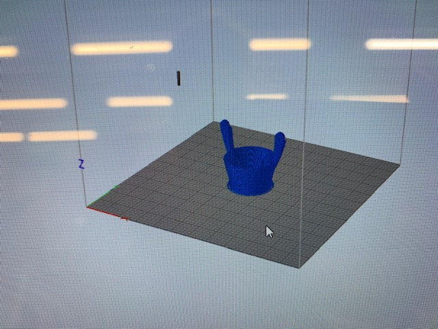
New cone design for the X-45 on the screen for printing
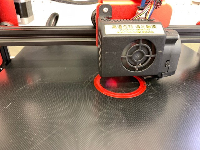
Printing started with regular PLA since my high temp filament had not been ordered yet
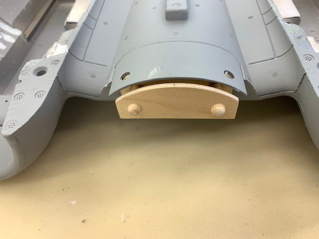
Pipe cone for X-45 indexed to rear turbine mounts for a 20mm spacing from leading edge of pipe.
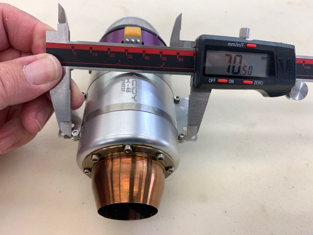
The design had to be adjusted slightly for the inside of the cone mounting arms to clear he turbine mounting clamp bolts.
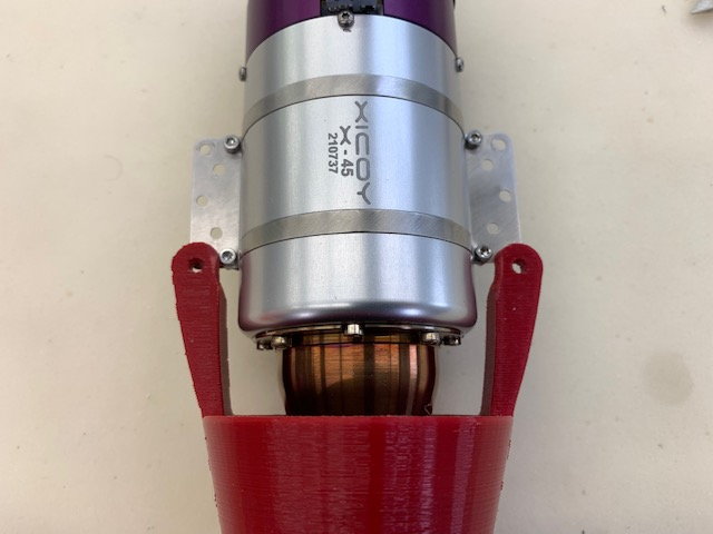
Relief cuts to clear the turbine strap bolts
The plan is to use one of Keith's 3D printed pipe bell mounts from high temp heat treated PLA. Keith has been using these pipe cones for a couple of years with great success. This cone is sized for the K-45 and is designed to use the rear holes of the turbine mount to index the proper spacing from turbine tail cone to the leading edge of the pipe. As the photo shows here the K-45 mounts are larger than the X45 so Keith sent me a new CAD file for the X-45.
New cone design for the X-45 on the screen for printing
Printing started with regular PLA since my high temp filament had not been ordered yet
Pipe cone for X-45 indexed to rear turbine mounts for a 20mm spacing from leading edge of pipe.
The design had to be adjusted slightly for the inside of the cone mounting arms to clear he turbine mounting clamp bolts.
Relief cuts to clear the turbine strap bolts
Last edited by Viper1GJ; 07-05-2022 at 12:45 PM.
The following 2 users liked this post by Viper1GJ:
drfred58809 (07-04-2022),
Halcyon66 (07-04-2022)
07-04-2022, 04:25 PM
#5
Thread Starter
My Feedback: (20)
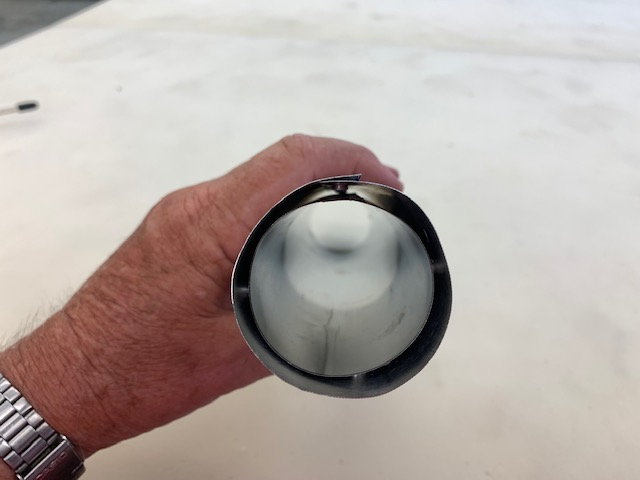
Fabricating Pipe
The plan is to use the same pipe as Keith has been making for a couple of years. It will be a dual wall pipe with inside diameter of 46mm and outer pipe of 52mm. The 3D printed cones are sized for 46mm diameter inner pipe
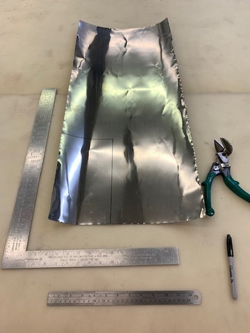
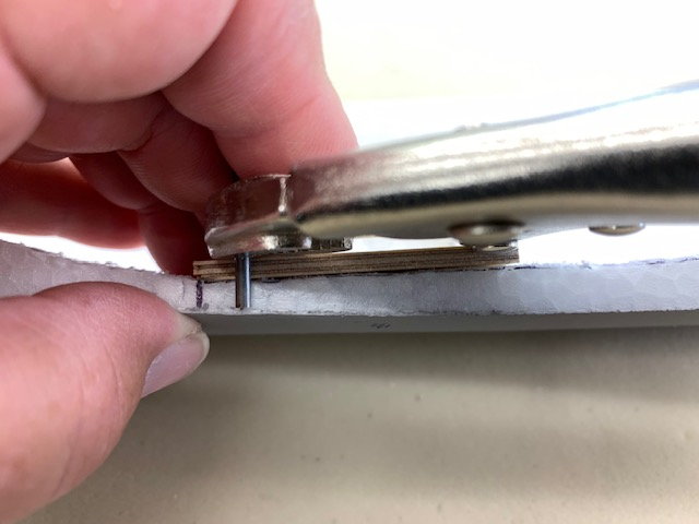
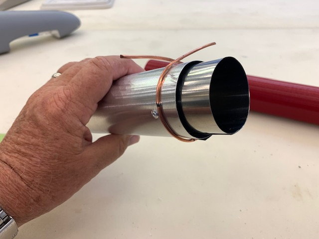
A damaged pipe I had in the shop was cut open to use the stainless steel for the inner pipe.
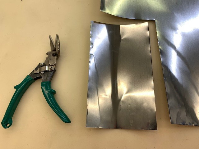
The size of the metal for the inner pipe is marked and cut. A 10mm overlap is planned for spot welding
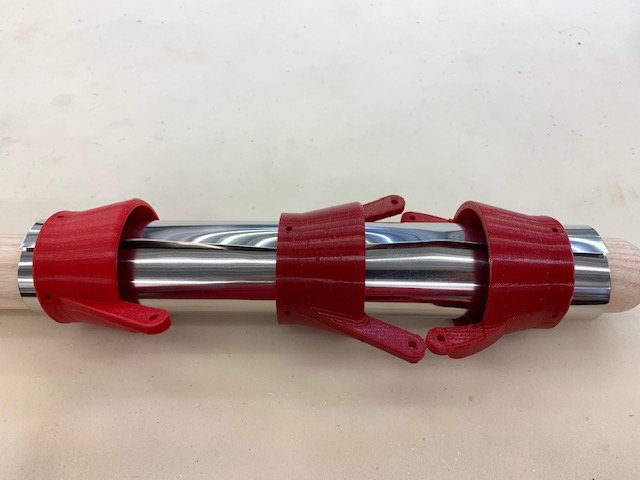
Since I now had 3 test printed pipe cones I used them for sizing collars during spot wielding to hold the proper diameter.
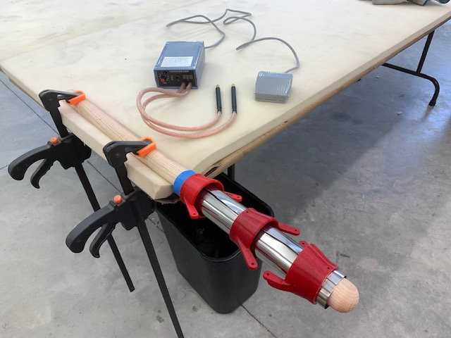
A 1.5" diameter table leg from Lowe's is used for a work mandrel and clamped to the work table. The pipe and collars are slid over the mandrel. The battery powered foot pedal controlled spot welder from Amazon is on the table charged and ready.
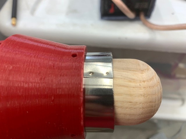
First spot welds to tack the end in place
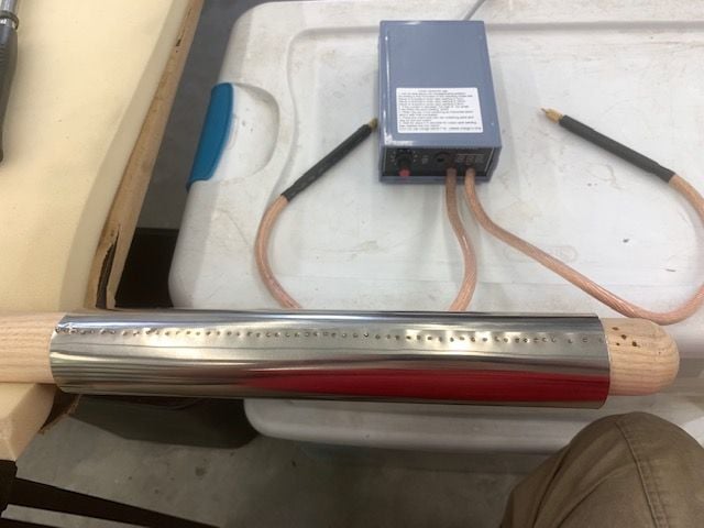
Spot welding complete and collars removed.
Test fit works good
The plan is to use the same pipe as Keith has been making for a couple of years. It will be a dual wall pipe with inside diameter of 46mm and outer pipe of 52mm. The 3D printed cones are sized for 46mm diameter inner pipe
A damaged pipe I had in the shop was cut open to use the stainless steel for the inner pipe.
The size of the metal for the inner pipe is marked and cut. A 10mm overlap is planned for spot welding
Since I now had 3 test printed pipe cones I used them for sizing collars during spot wielding to hold the proper diameter.
A 1.5" diameter table leg from Lowe's is used for a work mandrel and clamped to the work table. The pipe and collars are slid over the mandrel. The battery powered foot pedal controlled spot welder from Amazon is on the table charged and ready.
First spot welds to tack the end in place
Spot welding complete and collars removed.
Test fit works good
The following users liked this post:
drfred58809 (07-04-2022)
07-04-2022, 04:43 PM
#6
Thread Starter
My Feedback: (20)
Fabrication of outer pipe
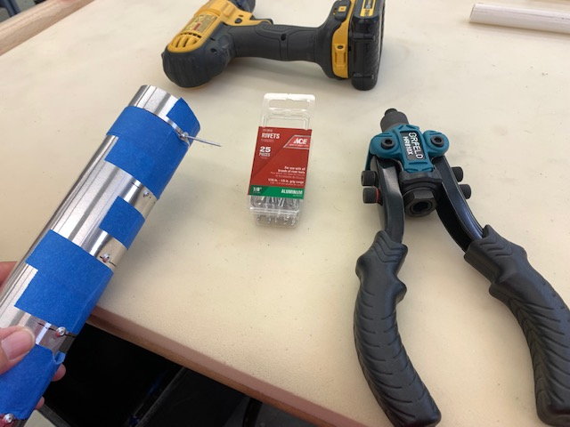
A 12" roll of aluminum roof flashing from Lowe's was used for the outer pipe material. The size for the outer pipe was marked and cut from the roll. 1/8" pop rivets from Ace Hardware were used for fasteners.

Holes drilled and pop rivets installed
Inside the outer pipe the pop rivets are used for stand off supports from the inner pipe
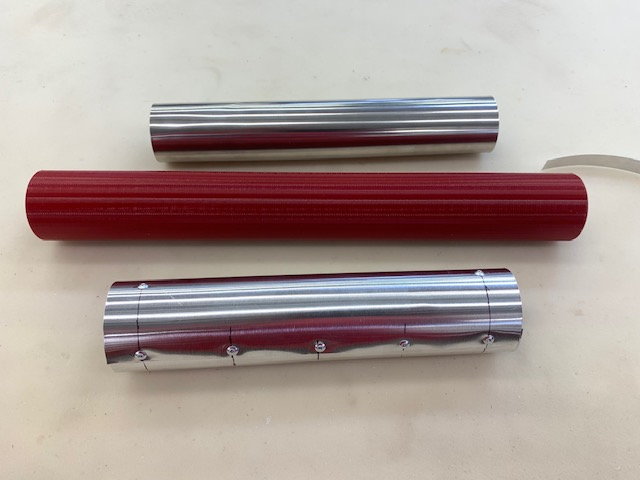
Inside pipe, outside pipe, and 3D printed 52mm sanding mandrel tool shown here.

Dremel sanding drum used to sand down the inside of the pop rivets so inside pipe would fit
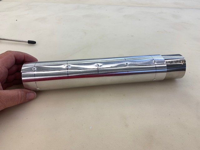
Inside pipe fit into outside pipe
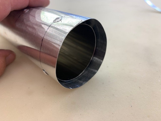
Inside pipe recessed 10mm on aft end to generate low pressure and suck cooling air between pipes.
Approximately 3mm gap all around. Not perfect but ok for my first homemade pipe
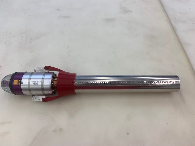
Test fit mock up works OK
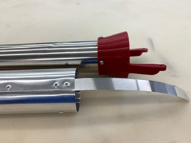
Aluminum holding strap riveted to bottom of outer pipe
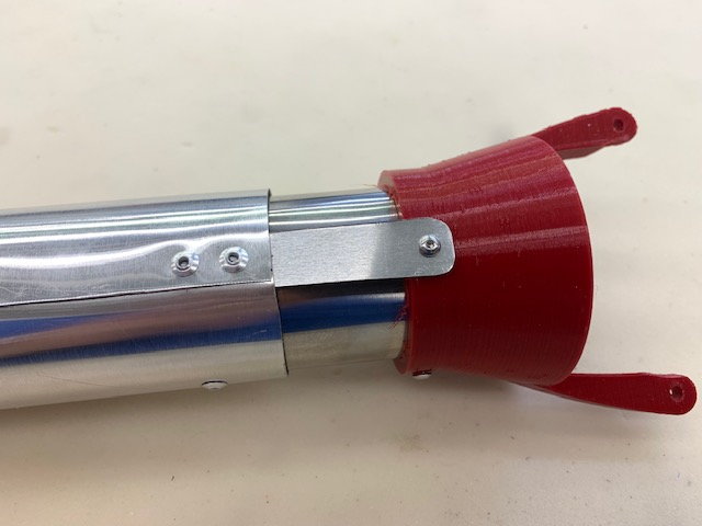
Holding strap cut, drilled, and attached to bell mount bolt to fasten outer pipe in place. Once the heat treated bell is printed and attached the bolts will be reversed so that the heads are inside the pipe and nuts are on the outside
A 12" roll of aluminum roof flashing from Lowe's was used for the outer pipe material. The size for the outer pipe was marked and cut from the roll. 1/8" pop rivets from Ace Hardware were used for fasteners.
Holes drilled and pop rivets installed
Inside the outer pipe the pop rivets are used for stand off supports from the inner pipe
Inside pipe, outside pipe, and 3D printed 52mm sanding mandrel tool shown here.
Dremel sanding drum used to sand down the inside of the pop rivets so inside pipe would fit
Inside pipe fit into outside pipe
Inside pipe recessed 10mm on aft end to generate low pressure and suck cooling air between pipes.
Approximately 3mm gap all around. Not perfect but ok for my first homemade pipe
Test fit mock up works OK
Aluminum holding strap riveted to bottom of outer pipe
Holding strap cut, drilled, and attached to bell mount bolt to fasten outer pipe in place. Once the heat treated bell is printed and attached the bolts will be reversed so that the heads are inside the pipe and nuts are on the outside
Last edited by Viper1GJ; 07-05-2022 at 09:38 AM.
The following 3 users liked this post by Viper1GJ:
The following users liked this post:
Viper1GJ (07-06-2022)


The following users liked this post:
Viper1GJ (07-06-2022)
07-05-2022, 05:50 AM
#10
Thread Starter
My Feedback: (20)
Removing foam for turbine mounts
Making turbine cut out pattern on card stock
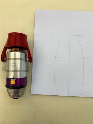
Turbine cut out shape transferred to card stock
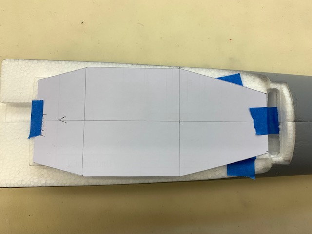
Turbine template taped to aft fuse
Pattern transferred to foam
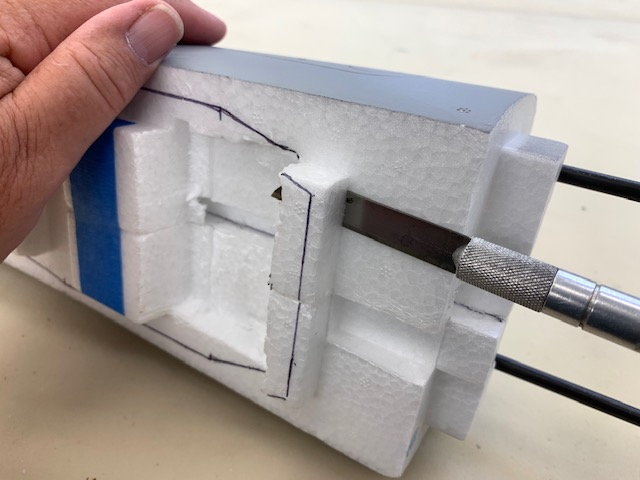
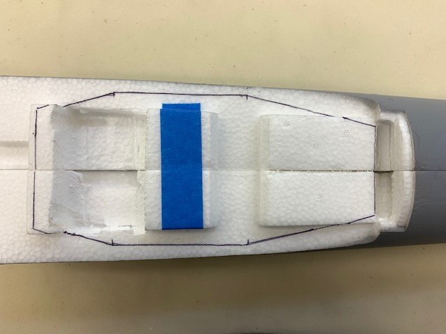
Foam removal started with knife
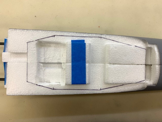
I was concerned about the thickness of foam remaining after fitting turbine in the fuse but I think it turned out OK
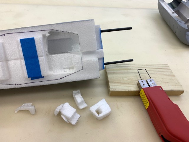
Foam nibbled out with hot wire cutter...
...and flush cut saw
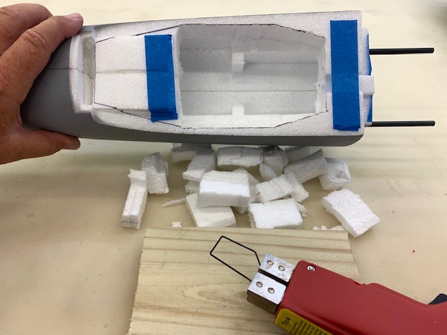
I removed little by little trying to avoid a big mistake in cutting away the foam
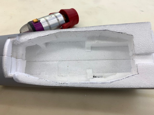
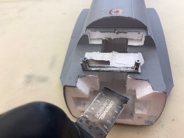
Turbine cavity in aft fuse
Test fit seems OK
Making turbine cut out pattern on card stock
Turbine cut out shape transferred to card stock
Turbine template taped to aft fuse
Pattern transferred to foam
Foam removal started with knife
I was concerned about the thickness of foam remaining after fitting turbine in the fuse but I think it turned out OK
Foam nibbled out with hot wire cutter...
...and flush cut saw
I removed little by little trying to avoid a big mistake in cutting away the foam
Turbine cavity in aft fuse
Test fit seems OK
07-05-2022, 06:04 AM
#11
Thread Starter
My Feedback: (20)
Installing turbine mounts
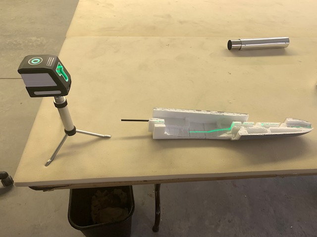
I used my laser level to project the thrust line down inside the area where the foam was removed
The laser when aligned with the marked lines allowed the thrust line to be accurately transferred to the fuse sides
1/8" plywood plates positioned 1/8" below thrust line and glued to foam with E6000 and allowed to dry
Setting the depth of cut for the turbine mount slots
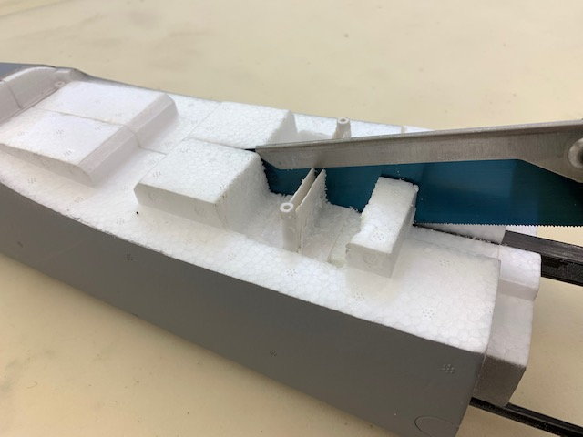
Foam slot cutting technique is from Paul A's videos
Ready to melt foam slot
It took about 4 to 5 reheats to cut and smooth out the slot
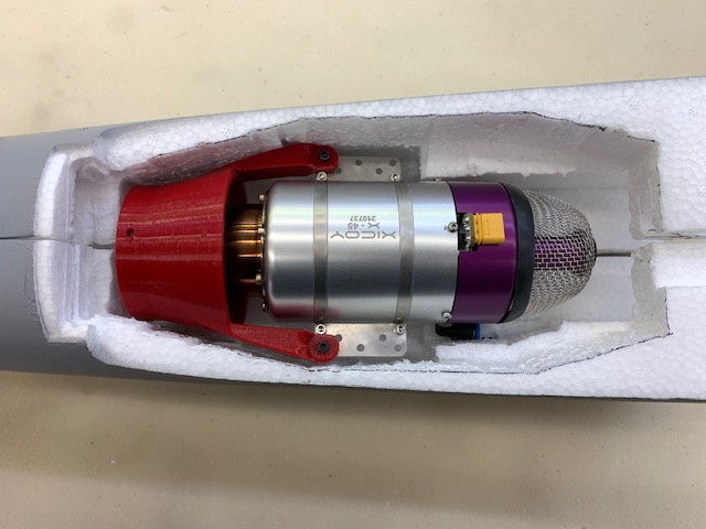
Turbine mount test fits.
Slot cutting technique workd great
NIce and tight fit
I was pleased with results
I used my laser level to project the thrust line down inside the area where the foam was removed
The laser when aligned with the marked lines allowed the thrust line to be accurately transferred to the fuse sides
1/8" plywood plates positioned 1/8" below thrust line and glued to foam with E6000 and allowed to dry
Setting the depth of cut for the turbine mount slots
Foam slot cutting technique is from Paul A's videos
Ready to melt foam slot
It took about 4 to 5 reheats to cut and smooth out the slot
Turbine mount test fits.
Slot cutting technique workd great
NIce and tight fit
I was pleased with results
07-05-2022, 06:36 AM
#12
Thread Starter
My Feedback: (20)
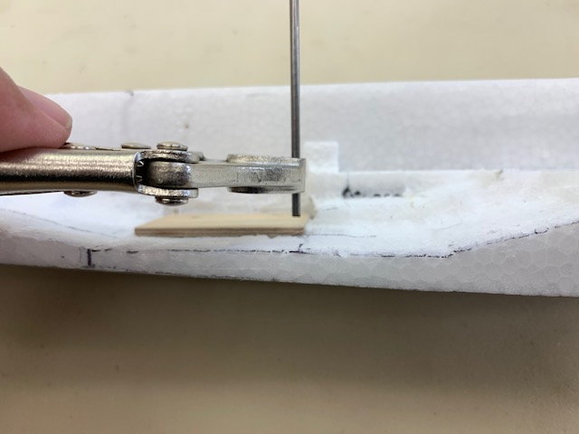
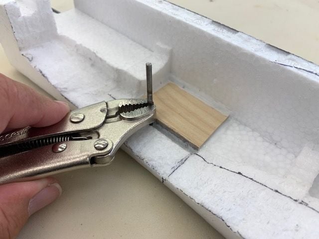
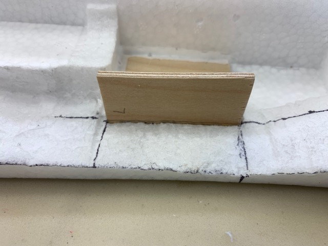
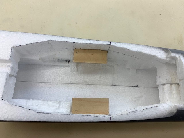
Installing turbine mounts
This is Paul's technique for centering and cutting the turbine mounts. Measure the distance between the turbine bracket bolts
Transfer this distance to a card stock template that will fit in the turbine cavity
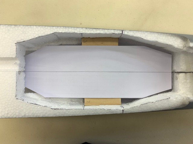
Align the template with the centerline of the fuse
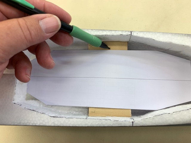
Mark the edges of the template on the turbine mounts
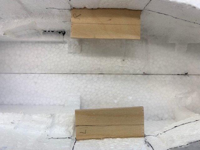
Turbine mounts marked and ready to cut
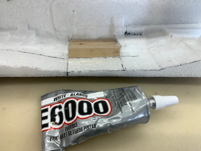
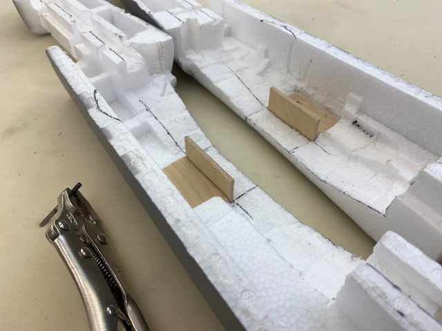
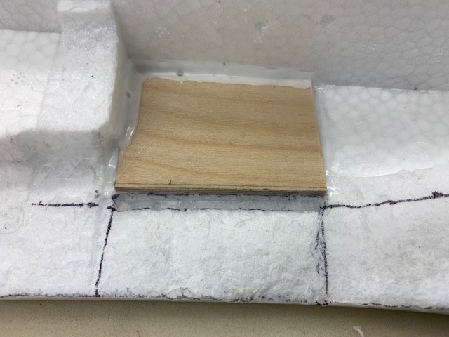
Mounts cut and glued in with E6000
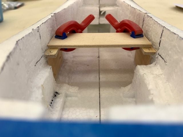
Clamp in a plywood bridge to keep the mounts square and let it dry
This is Paul's technique for centering and cutting the turbine mounts. Measure the distance between the turbine bracket bolts
Transfer this distance to a card stock template that will fit in the turbine cavity
Align the template with the centerline of the fuse
Mark the edges of the template on the turbine mounts
Turbine mounts marked and ready to cut
Mounts cut and glued in with E6000
Clamp in a plywood bridge to keep the mounts square and let it dry
The following users liked this post:
drfred58809 (07-05-2022)
07-05-2022, 06:51 AM
#13
Thread Starter
My Feedback: (20)
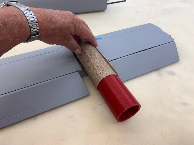
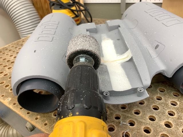
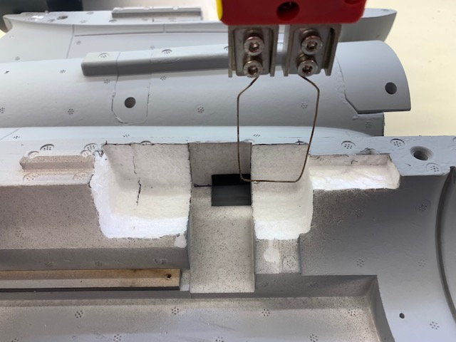
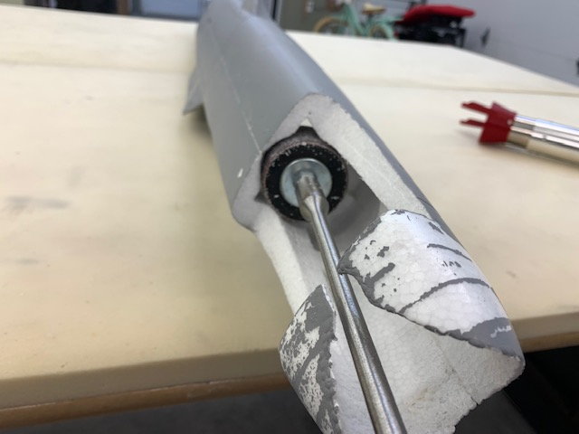
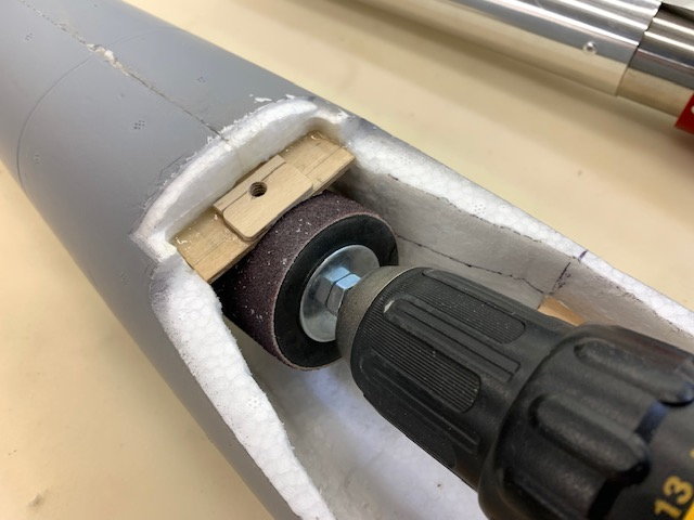
Cutting the pipe channel
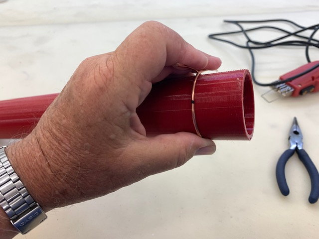
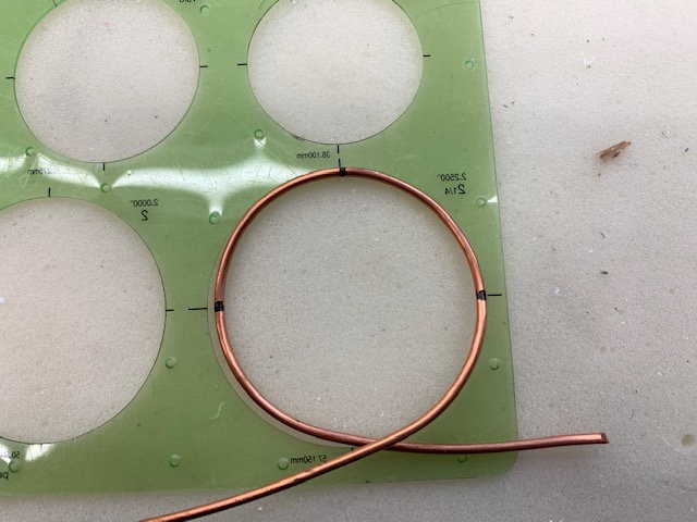
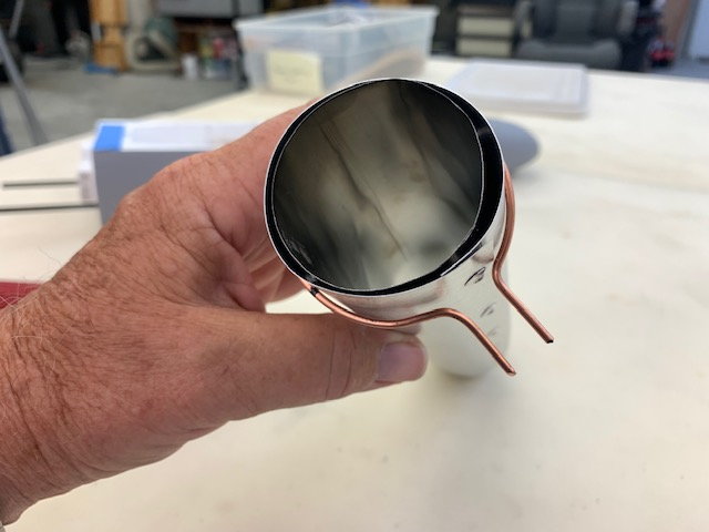
I started out trying to sand the cavity with the 3d printed mandrel and 80 grit paper but quickly looked for a faster way. I formed a copper wire around the mandrel
I sized the wire around the outer pipe
Turns out it was about 2.25" in diameter
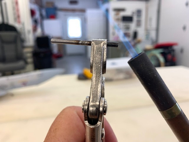
I formed the wire to fit in the hot wire cutter and it immediately fried the cutter.
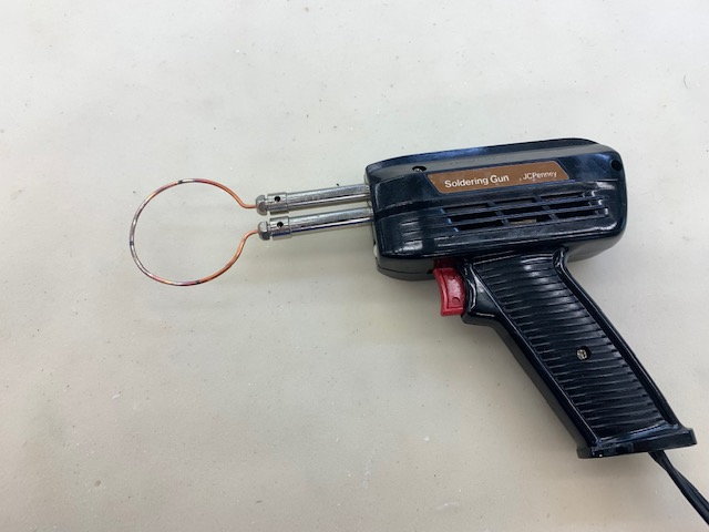
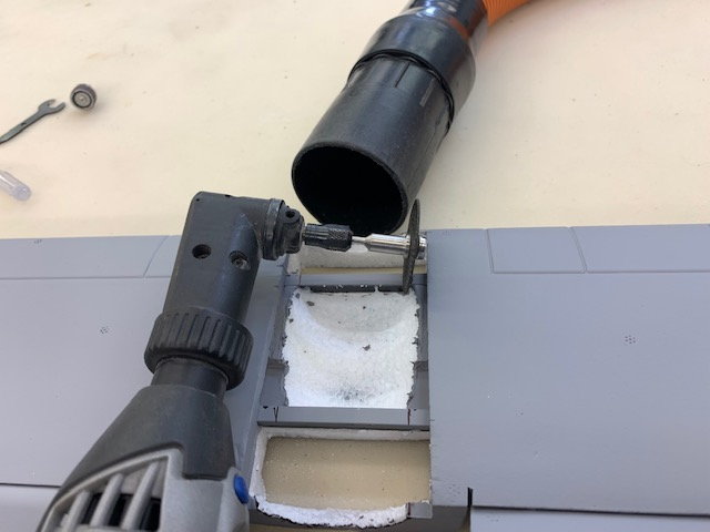
I then mounted it to my soldering gun and it got hot enough to cut the foam... but slowly
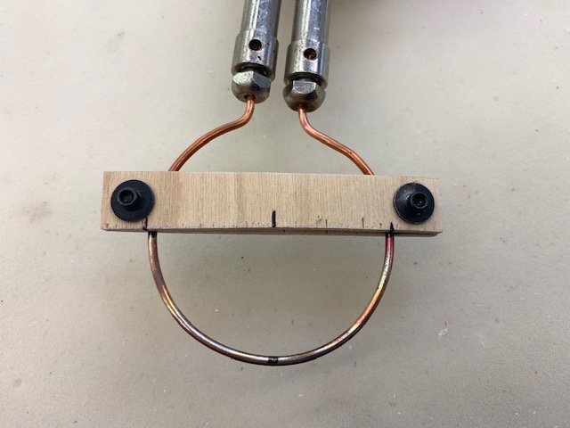
I rigged a quick depth of cut guide
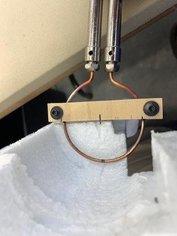
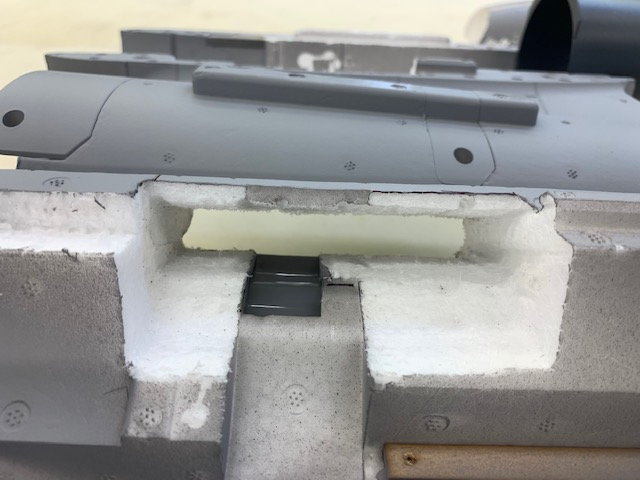
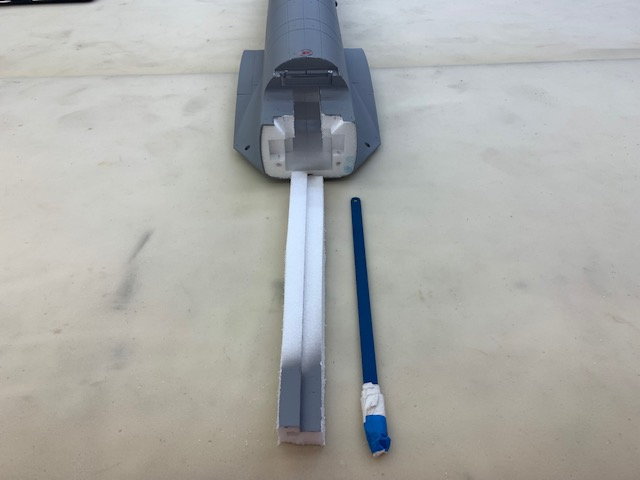
Then cut the channel freehand following lines drawn on the foam
It wasn't perfect but was good enough
I used the mandrel to clean up the channel

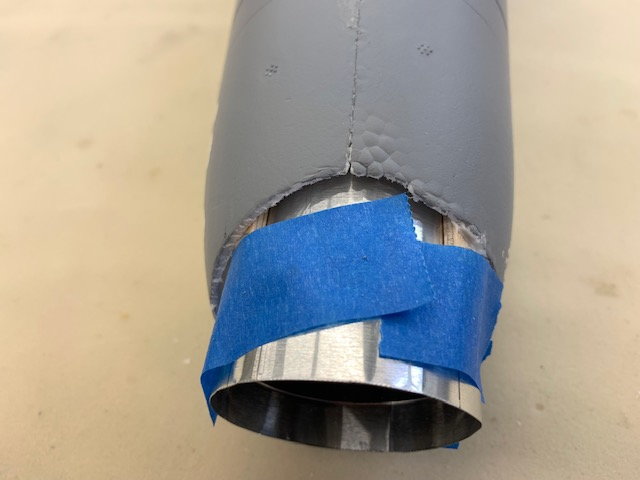
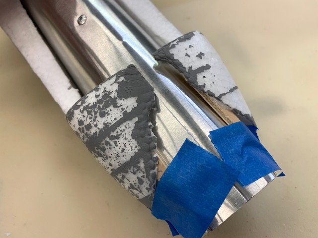
First test fit was good
The pipe exit hole was pretty bad and would have to be cleaned up
I started out trying to sand the cavity with the 3d printed mandrel and 80 grit paper but quickly looked for a faster way. I formed a copper wire around the mandrel
I sized the wire around the outer pipe
Turns out it was about 2.25" in diameter
I formed the wire to fit in the hot wire cutter and it immediately fried the cutter.
I then mounted it to my soldering gun and it got hot enough to cut the foam... but slowly
I rigged a quick depth of cut guide
Then cut the channel freehand following lines drawn on the foam
It wasn't perfect but was good enough
I used the mandrel to clean up the channel
First test fit was good
The pipe exit hole was pretty bad and would have to be cleaned up
Last edited by Viper1GJ; 07-05-2022 at 05:39 PM.
07-05-2022, 07:23 AM
#14
Thread Starter
My Feedback: (20)
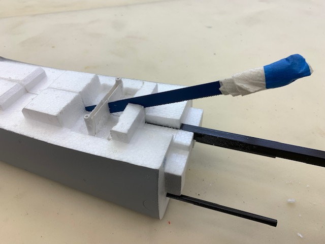
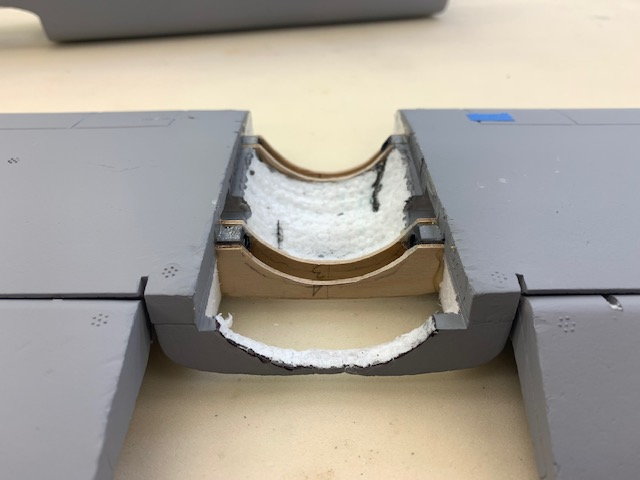
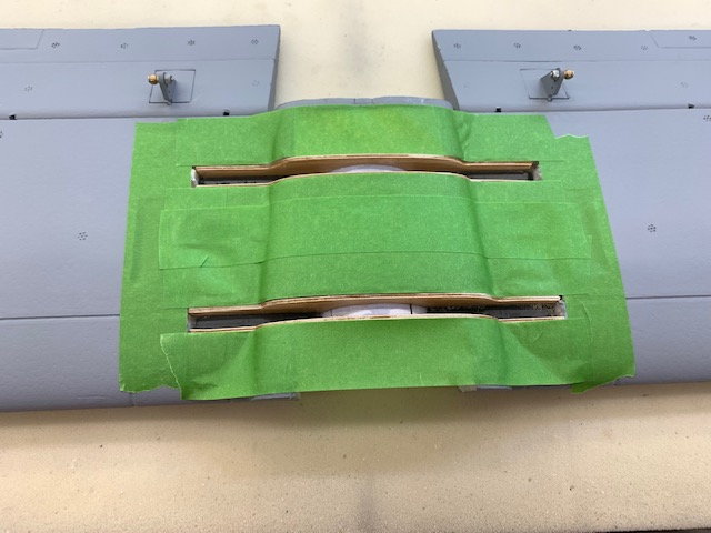
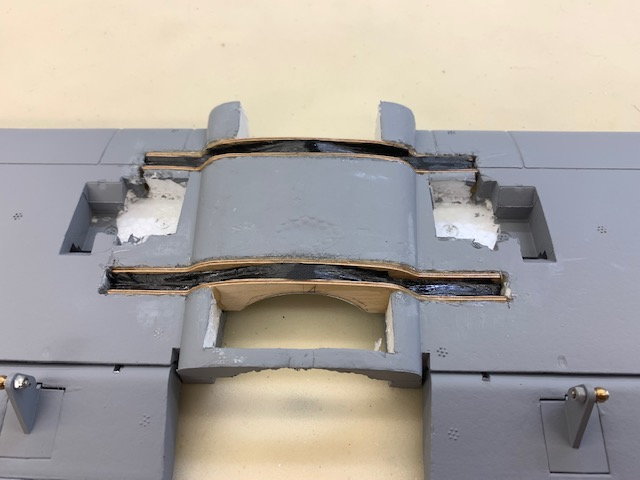
Cutting stab spars
Since the pipe goes right through the stab spars there was no other option except to cut them out. First the Freewing elevator servos were removed. They were glued in and had to be cut out. I hate gluing in servos but here there is no choice.
First the plastic stab mounts were removed exposing the carbon square tube spars
The center of the stab foam was cut out using the hot wire cutter and then the stab spars were cut away using a cutting wheel

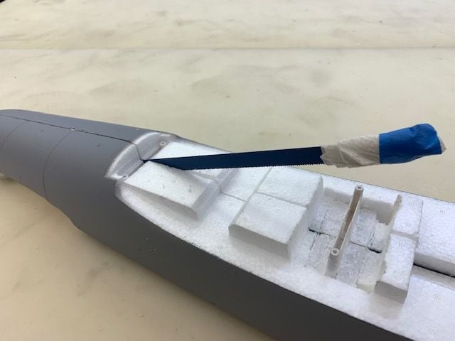
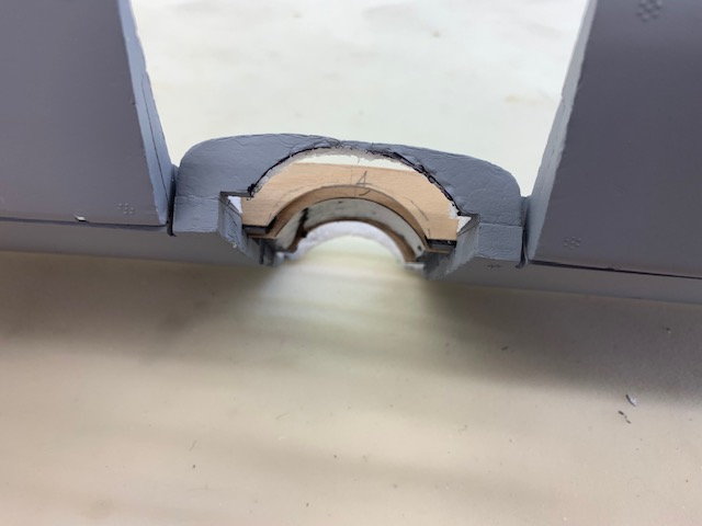
This pic shows the stab spars removed clearing the pipe channel... but you can see the stabs drooping since there is not much foam left to hold them together. This is where I remember thinking that this conversion method is not for the "faint of heart" since I have now gutted all structural integrity for the rear fuse and stab.
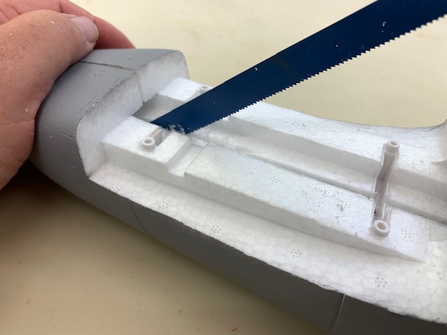
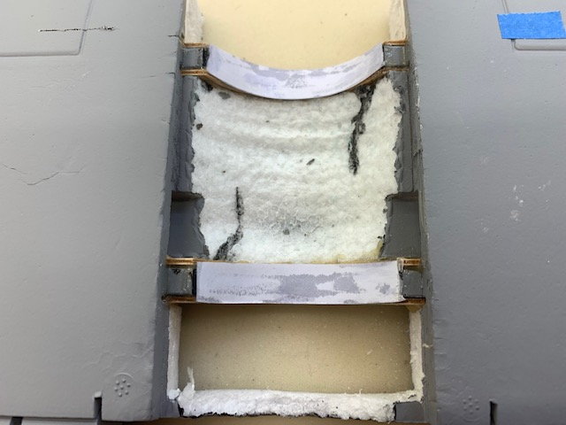
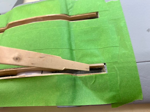
I decided to make some U shaped carry under spars out of carbon fiber. Here the lines for slots on front and back of the carbon spars are marked
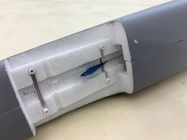
Freehand hot wire slot cuts made. I found hidden plywood stab root ribs embedded in the foam that held the carbon square tube spars
Slots complete and plywood ribs removed
Since the pipe goes right through the stab spars there was no other option except to cut them out. First the Freewing elevator servos were removed. They were glued in and had to be cut out. I hate gluing in servos but here there is no choice.
First the plastic stab mounts were removed exposing the carbon square tube spars
The center of the stab foam was cut out using the hot wire cutter and then the stab spars were cut away using a cutting wheel
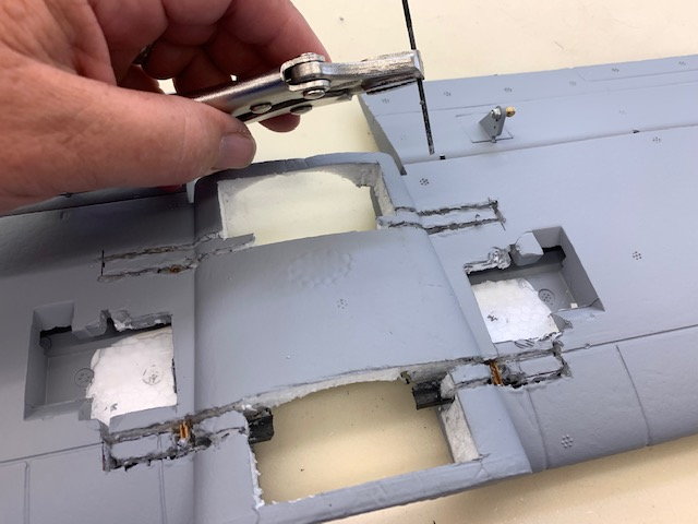
This pic shows the stab spars removed clearing the pipe channel... but you can see the stabs drooping since there is not much foam left to hold them together. This is where I remember thinking that this conversion method is not for the "faint of heart" since I have now gutted all structural integrity for the rear fuse and stab.
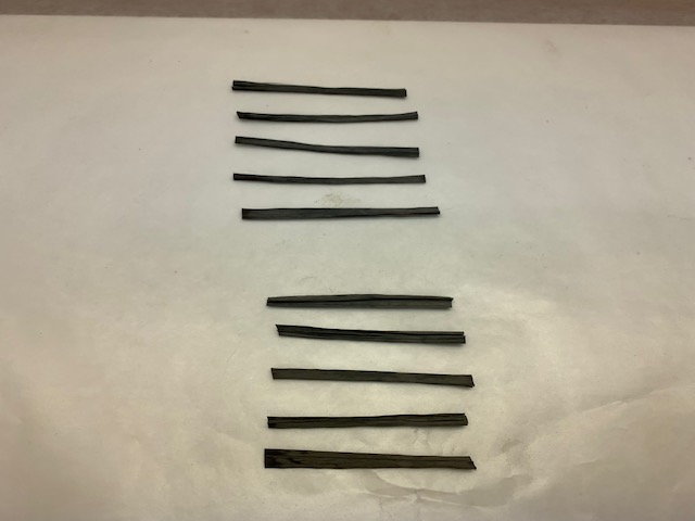
I decided to make some U shaped carry under spars out of carbon fiber. Here the lines for slots on front and back of the carbon spars are marked
Freehand hot wire slot cuts made. I found hidden plywood stab root ribs embedded in the foam that held the carbon square tube spars
Slots complete and plywood ribs removed
07-05-2022, 07:34 AM
#15
Thread Starter
My Feedback: (20)
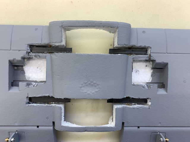
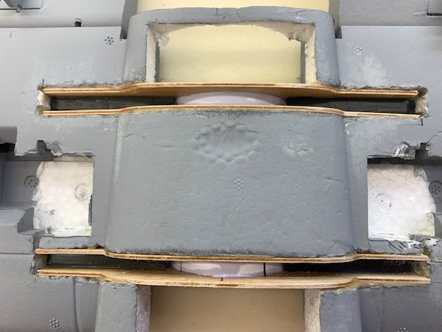
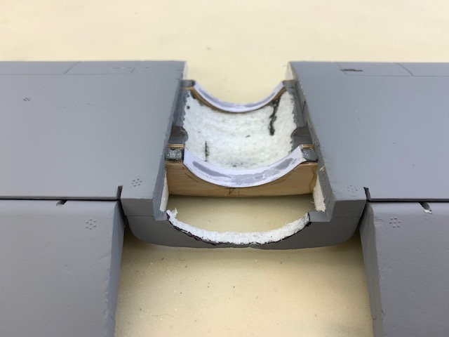
Preparing for carbon tow carry under spars
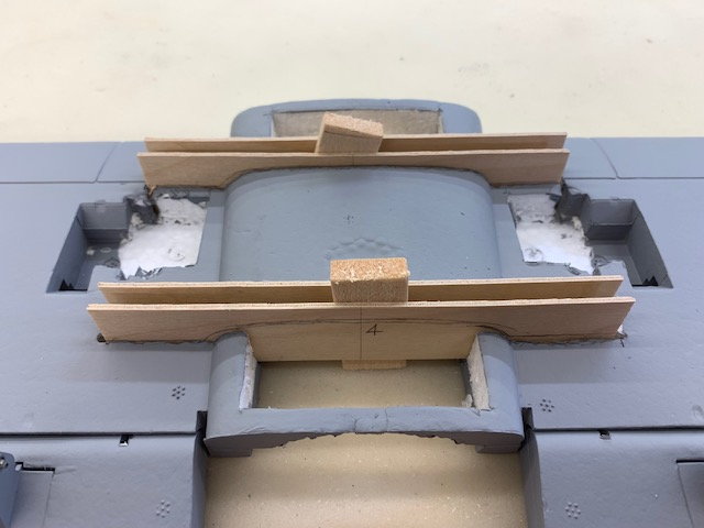
1/16" ply spar formers were fabricated
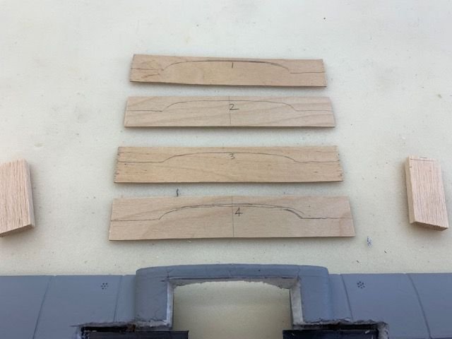
Spar formers marked and ready to cut
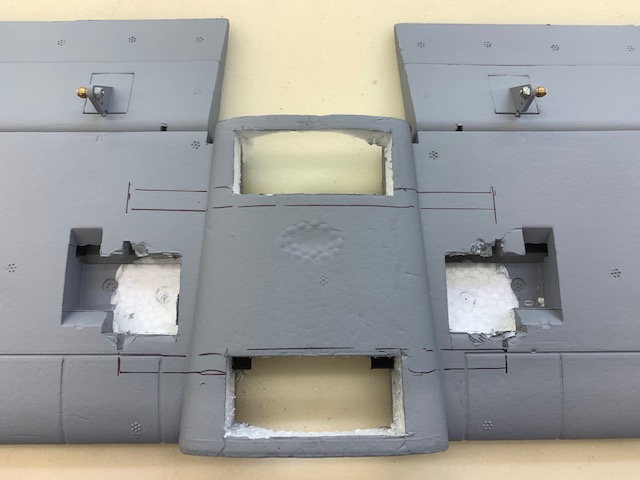
Dry fit of spar formers after cutting
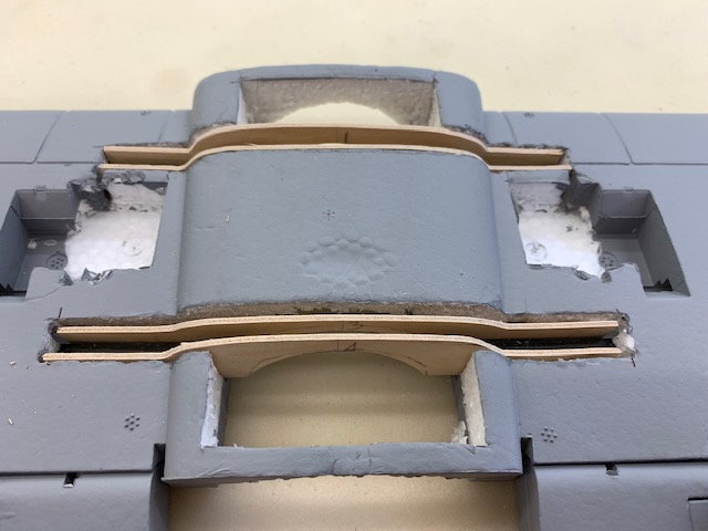
Bottom view of spar formers with pipe channel cut out
Balsa separators dry fit to keep the formers square
Spar formers glued in with thickened epoxy
Epoxy cured
Pipe channel sanded smooth and high spots removed with sanding mandrel and 80 grit paper
Finished spar formers
1/16" ply spar formers were fabricated
Spar formers marked and ready to cut
Dry fit of spar formers after cutting
Bottom view of spar formers with pipe channel cut out
Balsa separators dry fit to keep the formers square
Spar formers glued in with thickened epoxy
Epoxy cured
Pipe channel sanded smooth and high spots removed with sanding mandrel and 80 grit paper
Finished spar formers
07-05-2022, 08:00 AM
#16
Thread Starter
My Feedback: (20)
Carbon tow spars fabricated
Card stock paper glued on top of spar formers with CA to seal the gap between them
Card stock gap seal view from bottom show channel between spar formers to lay in carbon tow
Area taped off to keep epoxy off surfaces
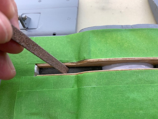
Stab carbon spar tubes scratched and scuffed with Perma Grit file to get good bond of carbon tow
Popsicle stick stuffing tool made to stuff carbon tow down into spar channel
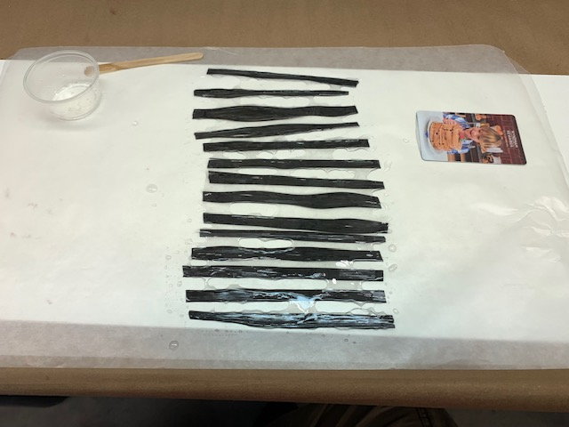
19 long strips of carbon tow wetted out on wax paper and stuffed into each channel of front and rear stab spars. The scientific number of 19 was because that's how many I got laid out on the first strip of wax paper, so I just did it again for the other spar!
Next 4 short strips were wetted out for each spar. Turns out it was a good guess since it filled the channel up in the center
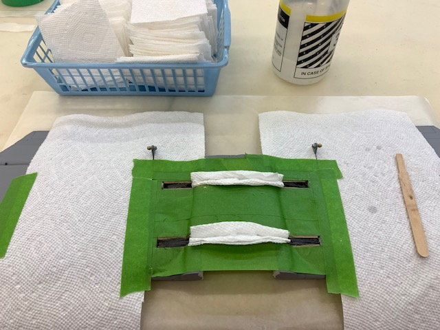
Paper towel squares stuffed in the channels to absorb excess epoxy
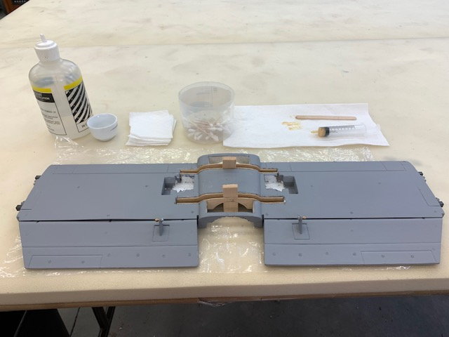
Finished layup of both spars
Peel ply strip placed over the spar layups and tape added to keep it flat
Layup cured and tape removed
View from top after cure
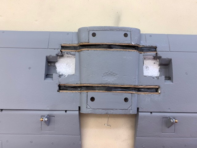
Foam plugs replaced in front and aft of stab
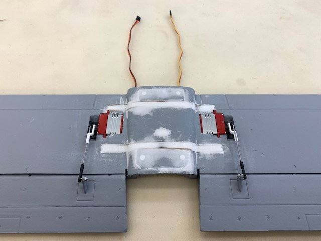
Foam filler applied and sanded and new Promodler HV elevator servos dry fit
Card stock paper glued on top of spar formers with CA to seal the gap between them
Card stock gap seal view from bottom show channel between spar formers to lay in carbon tow
Area taped off to keep epoxy off surfaces
Stab carbon spar tubes scratched and scuffed with Perma Grit file to get good bond of carbon tow
Popsicle stick stuffing tool made to stuff carbon tow down into spar channel
19 long strips of carbon tow wetted out on wax paper and stuffed into each channel of front and rear stab spars. The scientific number of 19 was because that's how many I got laid out on the first strip of wax paper, so I just did it again for the other spar!
Next 4 short strips were wetted out for each spar. Turns out it was a good guess since it filled the channel up in the center
Paper towel squares stuffed in the channels to absorb excess epoxy
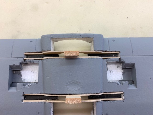
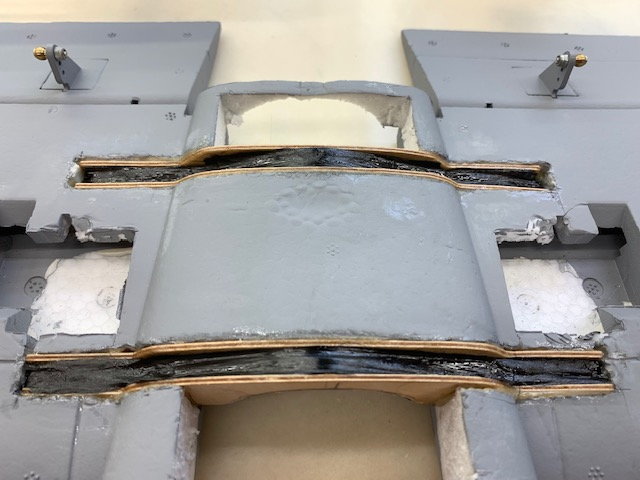
Finished layup of both spars
Peel ply strip placed over the spar layups and tape added to keep it flat
Layup cured and tape removed
View from top after cure
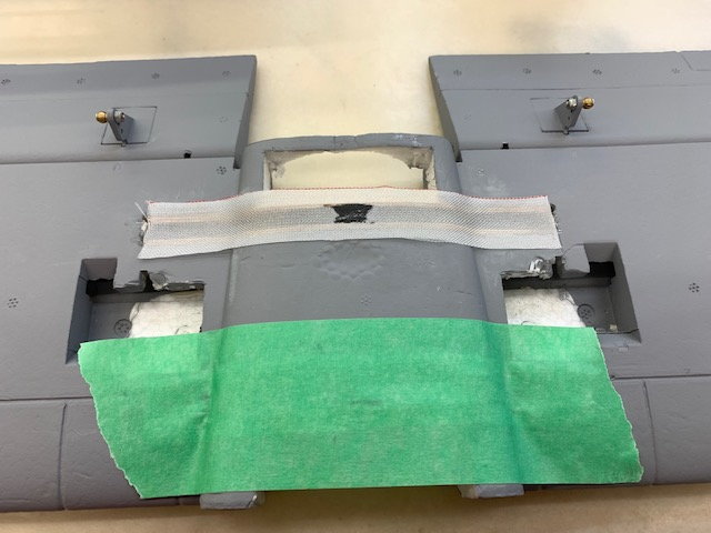
Foam plugs replaced in front and aft of stab
Foam filler applied and sanded and new Promodler HV elevator servos dry fit
Last edited by Viper1GJ; 07-05-2022 at 01:11 PM.
The following users liked this post:
Viper1GJ (07-06-2022)
07-05-2022, 09:29 AM
#18
Thread Starter
My Feedback: (20)
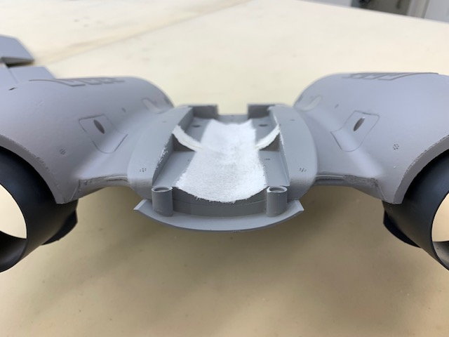
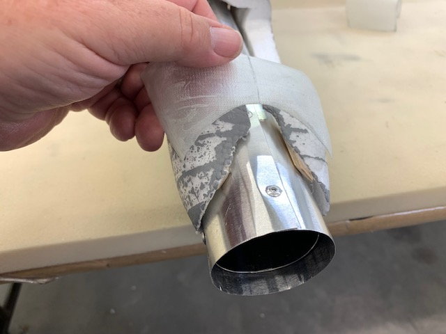
Fabricating and fitting rear pipe exit from fiberglass parts
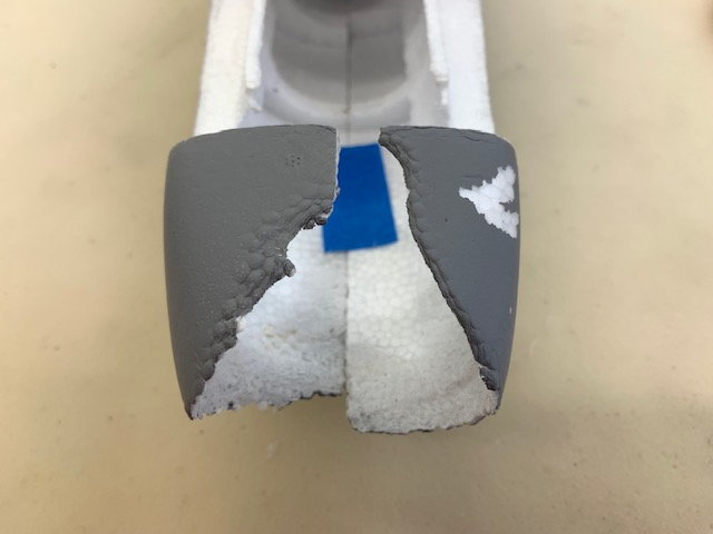
Here is the bottom tail cone after the freehand pipe channel hot wire cuts. Not pretty and I had failed to make the fiberglass part on step one above.
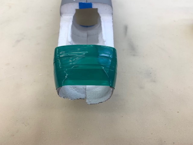
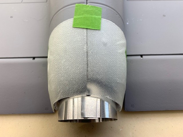
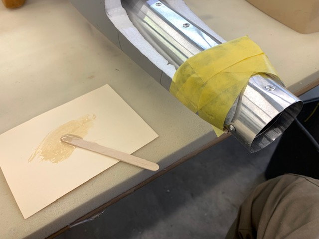
I put a wood spreader between the sides so they would not pull together and used vinyl tape to make the bottom fuse mold shape
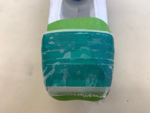
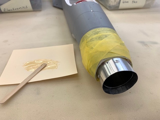
Same steps as described in step one above, wax, 2 layers glass, pattern cut and applied
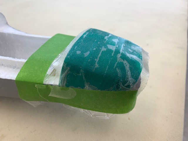
Glass wrapped around mold
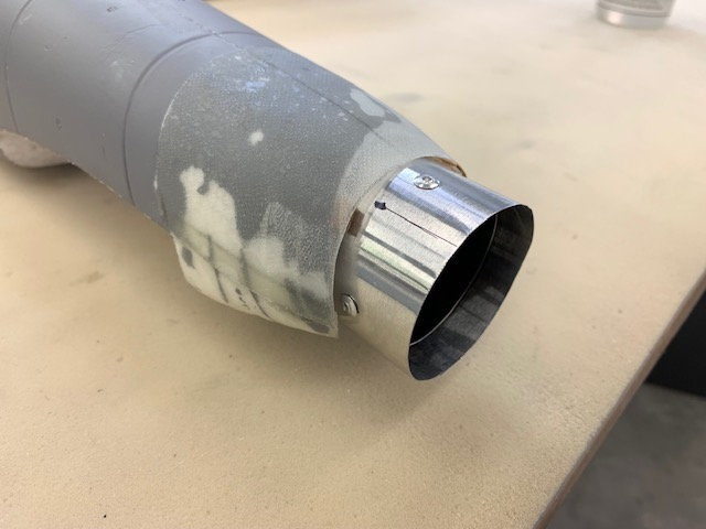
Epoxy cured
Tape removed and parts in place for marking
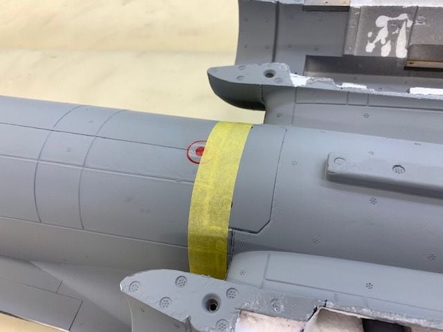
Trim tape used to lay out cut lines
Ready for cutting
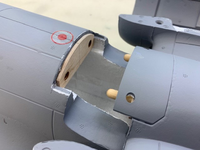
Top piece cut and placed over bottom piece
Pipe exit hole marked
Pipe exit hole on bottom marked
Cutting top piece
Bottom piece marked and ready for cut
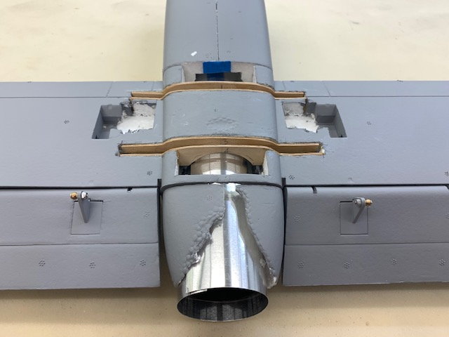
Bottom piece cut and pipe dry fit test
Pipe dry fit test from top
Here is the bottom tail cone after the freehand pipe channel hot wire cuts. Not pretty and I had failed to make the fiberglass part on step one above.
I put a wood spreader between the sides so they would not pull together and used vinyl tape to make the bottom fuse mold shape
Same steps as described in step one above, wax, 2 layers glass, pattern cut and applied
Glass wrapped around mold
Epoxy cured
Tape removed and parts in place for marking
Trim tape used to lay out cut lines
Ready for cutting
Top piece cut and placed over bottom piece
Pipe exit hole marked
Pipe exit hole on bottom marked
Cutting top piece
Bottom piece marked and ready for cut
Bottom piece cut and pipe dry fit test
Pipe dry fit test from top
07-05-2022, 12:36 PM
#19
Thread Starter
My Feedback: (20)
Turbine hatch prep
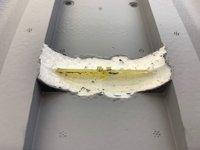
I needed to clear some foam from right above the turbine so I hot wired the foam rib and found a G10 spar imbedded
Switched to sanding drum and made the curved cut out
This provides additional clearance above the turbine for air flow to pipe and cooling
View of hatch above turbine from front
Turbine hatch dry fit
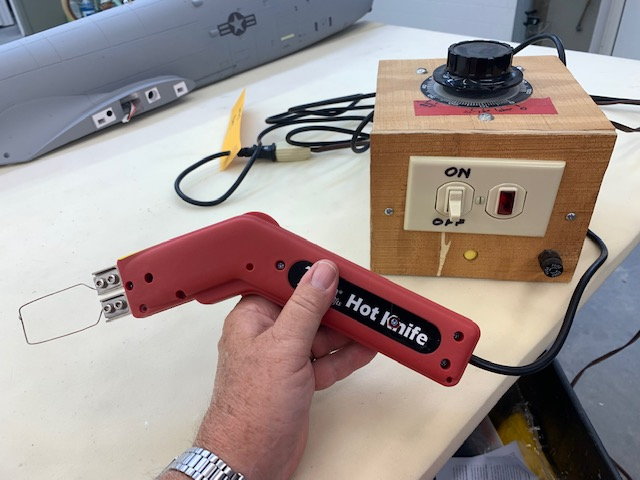
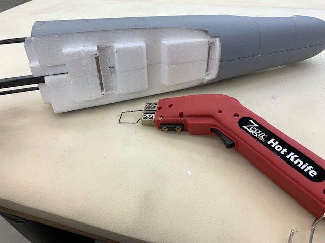
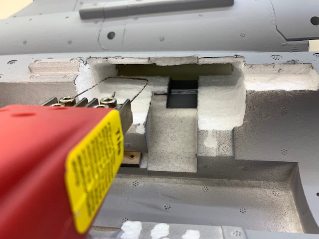
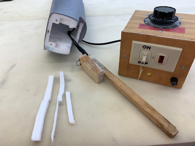
I really needed a longer hot wire cutter so I gutted the insides of the cheap hot knife and threw them away. I connected the heavy duty terminals to a nichrome wire and directly connected the terminals to my foam wing cutting transformer and it worked great.
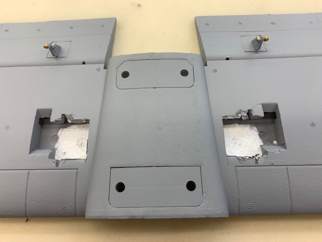
I started nibbling away at the ESC wire channel to make a turbine air intake duct inside the nacelle pylon
Almost complete
Right side
Left side
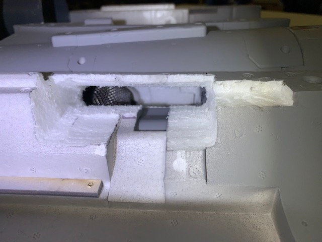
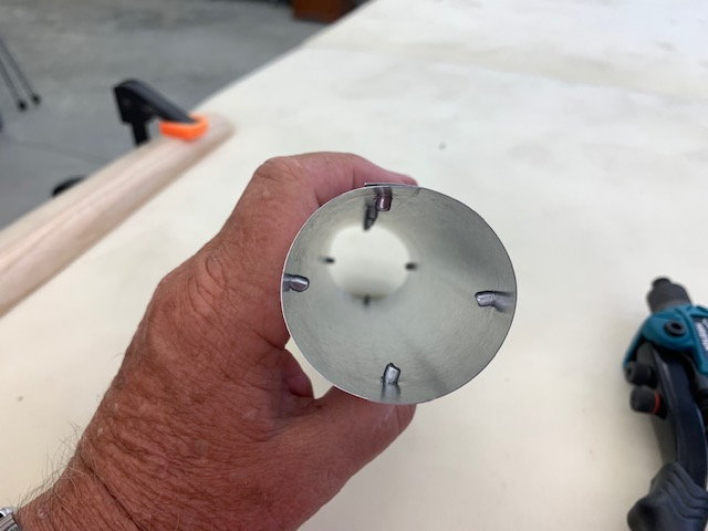
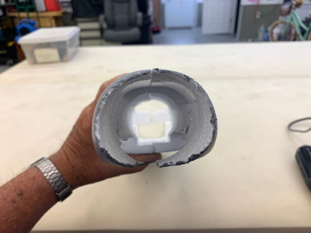
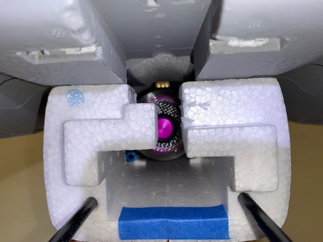
View of turbine FOD screen inside the fuse as seen by an air molecule entering the front of the nacelle.

Painted two coats of Polycrylic on the sanded foam and sanded off foam fuzz. Now I did not have to worry about cutting any cheater holes in the fuse. Plenty of intake area from both sides from the scale intakes high enough to avoid grass FOD from the gear...I hope!
I needed to clear some foam from right above the turbine so I hot wired the foam rib and found a G10 spar imbedded
Switched to sanding drum and made the curved cut out
This provides additional clearance above the turbine for air flow to pipe and cooling
View of hatch above turbine from front
Turbine hatch dry fit
I really needed a longer hot wire cutter so I gutted the insides of the cheap hot knife and threw them away. I connected the heavy duty terminals to a nichrome wire and directly connected the terminals to my foam wing cutting transformer and it worked great.
I started nibbling away at the ESC wire channel to make a turbine air intake duct inside the nacelle pylon
Almost complete
Right side
Left side
View of turbine FOD screen inside the fuse as seen by an air molecule entering the front of the nacelle.
Painted two coats of Polycrylic on the sanded foam and sanded off foam fuzz. Now I did not have to worry about cutting any cheater holes in the fuse. Plenty of intake area from both sides from the scale intakes high enough to avoid grass FOD from the gear...I hope!
Last edited by Viper1GJ; 07-05-2022 at 01:05 PM.
07-05-2022, 12:57 PM
#20
Thread Starter
My Feedback: (20)
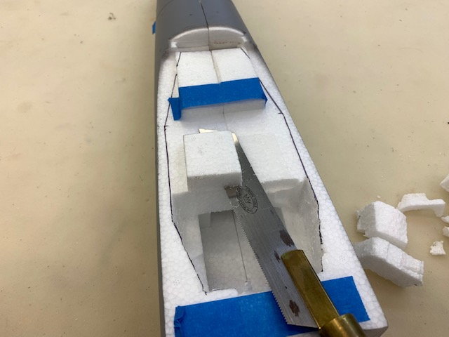
Gutting front fuse
With most of the rear fuse complete the rear fuse halves were glued back together and I turned to the front fuse
Started removing foam for a fuel tank placed on the CG with a hack saw blade

The first cuts were pretty easy
The long center section removed
A Dremel oscillating saw used to remove the plastic front hatch mounts
Next I used an old foam wing spar cutter taped to a stick to hot wire cut the foam from each fuse side
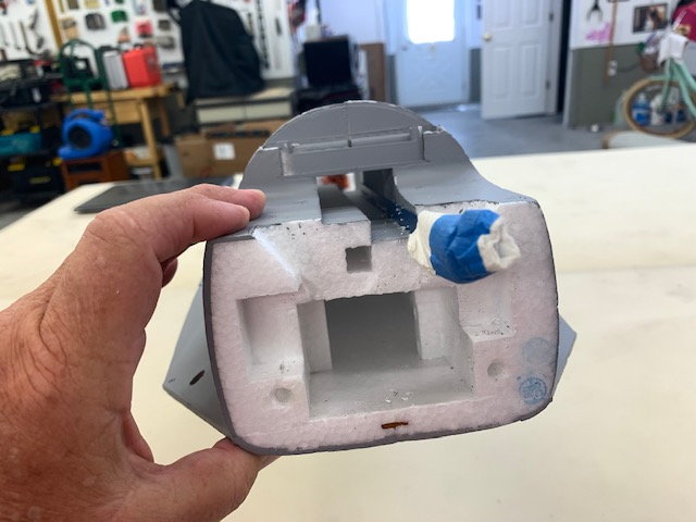
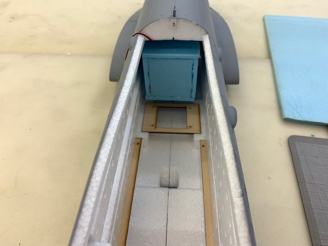
Results came out pretty good. View from the cockpit hatch
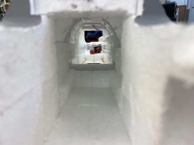
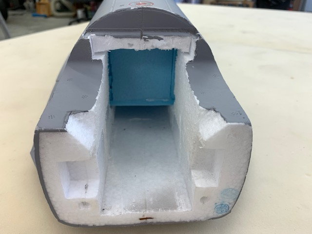
View from the rear of the front fuse section
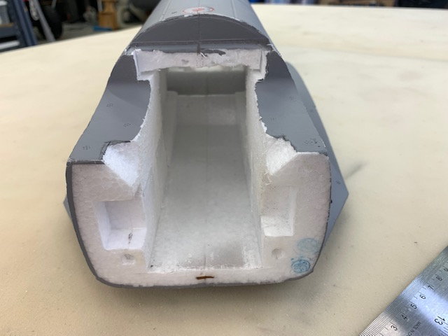
Rear of front fuse. Still some foam left here for good structure
With most of the rear fuse complete the rear fuse halves were glued back together and I turned to the front fuse
Started removing foam for a fuel tank placed on the CG with a hack saw blade
The first cuts were pretty easy
The long center section removed
A Dremel oscillating saw used to remove the plastic front hatch mounts
Next I used an old foam wing spar cutter taped to a stick to hot wire cut the foam from each fuse side
Results came out pretty good. View from the cockpit hatch
View from the rear of the front fuse section
Rear of front fuse. Still some foam left here for good structure
Last edited by Viper1GJ; 07-05-2022 at 05:41 PM.
07-05-2022, 01:26 PM
#21
Thread Starter
My Feedback: (20)
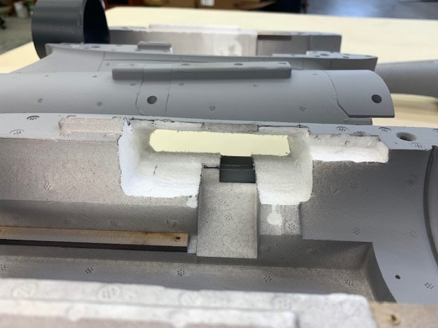
Fuel tank mock up
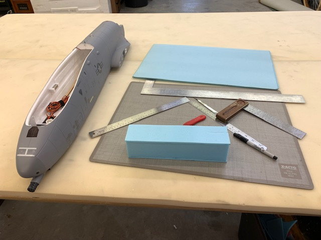
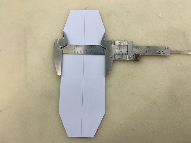
Initial measurements showed a 70mm x 80mm 320mm fuel tank would fit right over the CG. I made one and discovered it would not through the cockpit hatch so made the mock up 70mm x 70mm x 320mm and it worked OK
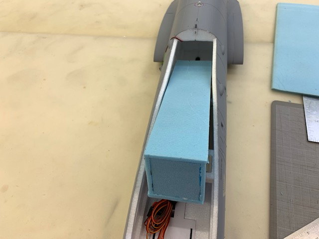
Test fit through cockpit hatch
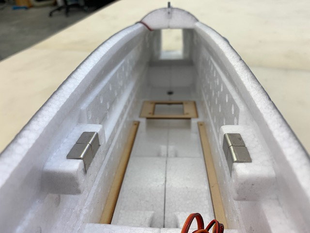
Tank fit right over CG which is basically the front wing spar
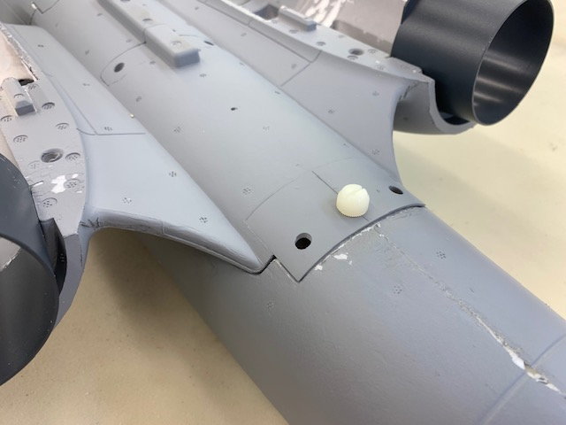
View from aft of front fuse
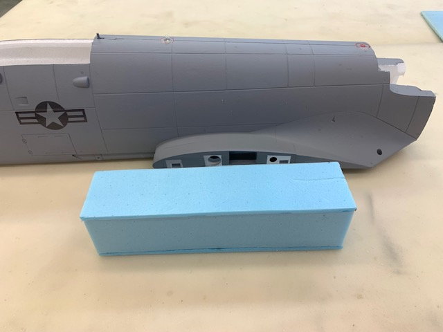
Approximate location beside fuse. Tank is centered on front wing tube. Initial estimate was for approximately 1.4L or about 46 oz which is plenty for the X-45.
Initial measurements showed a 70mm x 80mm 320mm fuel tank would fit right over the CG. I made one and discovered it would not through the cockpit hatch so made the mock up 70mm x 70mm x 320mm and it worked OK
Test fit through cockpit hatch
Tank fit right over CG which is basically the front wing spar
View from aft of front fuse
Approximate location beside fuse. Tank is centered on front wing tube. Initial estimate was for approximately 1.4L or about 46 oz which is plenty for the X-45.
07-05-2022, 01:37 PM
#22
Thread Starter
My Feedback: (20)
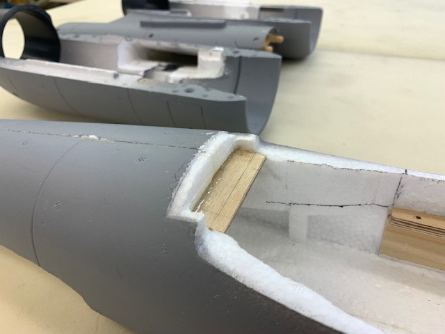
Joining front and rear fuse and front hatch mounts
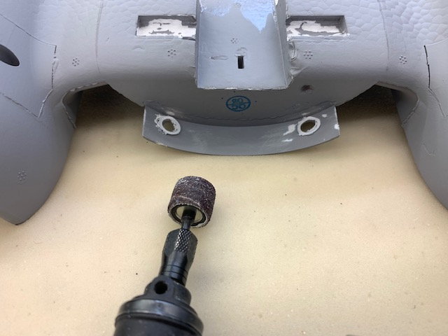
Plastic screw sleves ground away
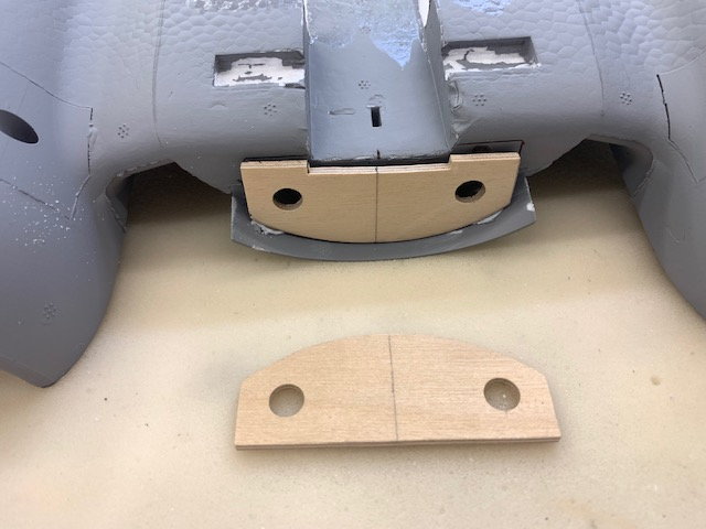
Two plywood templates cut
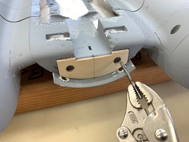
Dowel holes melted with hot wire
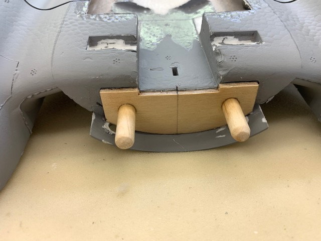
Dowels epoxied in place
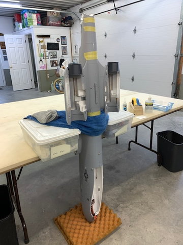
Front and rear fuse sections joined together
Weights used to keep the fuse from falling over during glue cure
Front plate ready for glue and mating to front fuse
Rear of hatch taped down for glue to dry
Front hatch dowels complete
Rear hatch hold down installed
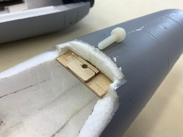
Plywood doubler installed, drilled and threaded for 1/4-20 nylon thumb bolt
Rear hatch hold down complete
Plastic screw sleves ground away
Two plywood templates cut
Dowel holes melted with hot wire
Dowels epoxied in place
Front and rear fuse sections joined together
Weights used to keep the fuse from falling over during glue cure
Front plate ready for glue and mating to front fuse
Rear of hatch taped down for glue to dry
Front hatch dowels complete
Rear hatch hold down installed
Plywood doubler installed, drilled and threaded for 1/4-20 nylon thumb bolt
Rear hatch hold down complete
Last edited by Viper1GJ; 07-05-2022 at 05:33 PM.
07-05-2022, 04:57 PM
#23
Thread Starter
My Feedback: (20)
3D printed fuel and air trap tanks
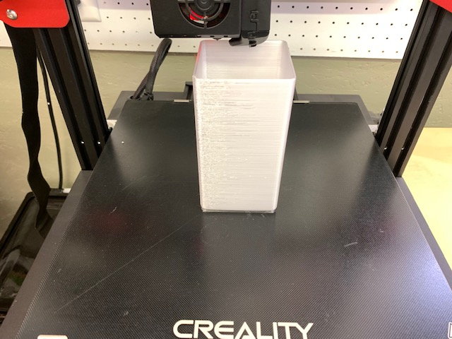
Keith sent me the .stl files for the fuel tank. He calculate 1.3L or 44 oz. Plenty for the X-45. Back end printing here in translucent PETG filament. Keith loaded the fuel tank files up to Thingiverse so anyone could download and use them. Thanks Keith!
https://www.thingiverse.com/thing:5422922
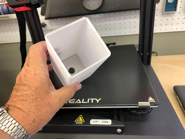
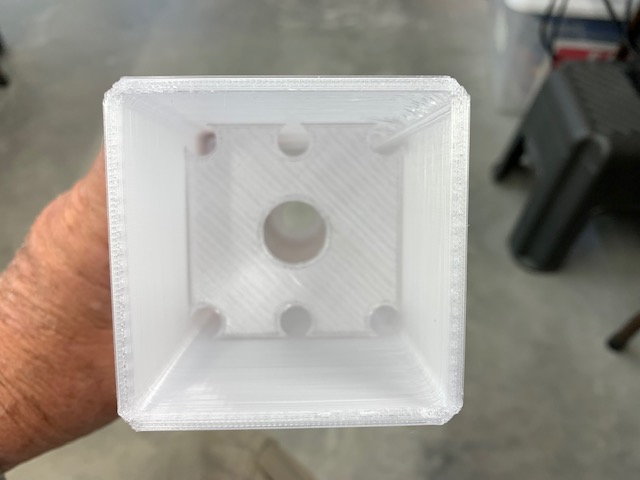
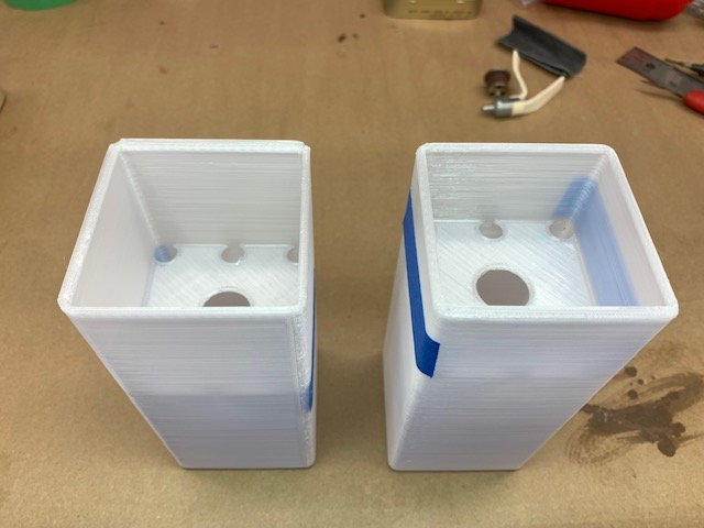
Front end off printer. Designed for a standard Dubro stopper
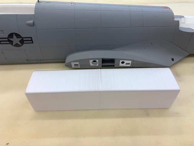
Tank parts staged beside fuse
Two baffles were printed and installed to prevent excess sloshing in the long tank
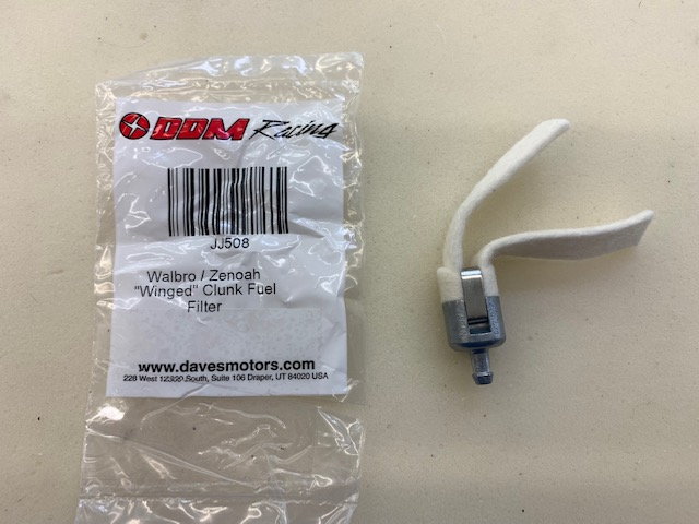
Winged felt clunk used...I've used these in all my foamy conversions and they suck out all of the fuel
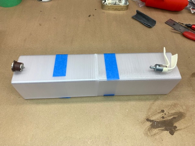
Tank hardware and baffle layout. Baffles were installed on right edge of the blue tape. The rear end has a little more space for the clunk to flop around in
Baffles were tacked in with thin CA
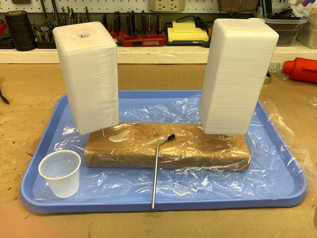
Tanks coated on inside with laminating epoxy. I used West Systems. Bent brush was to make sure the epoxy got everywhere behind the baffles. Sharpened coat hanger wire stands held the tank halves up during cure
After inside cure the tank seam edges were sanded and then bonded together with thickened epoxy and allowed to cure. Then the joint was wrapped with two layers of glass tape and the outside was coated with epoxy and allowed to cure. A single coat hanger wire up the center held the tank up during cure (sorry no pic)
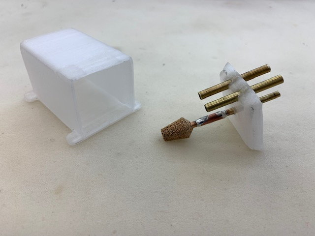
AIr trap tank parts printed and brass tubes and filter pickup installed. Keith also loaded the air trap tank on to Thingiverse. There are two versions, one with pump mounting lugs for the K-45 pump on top and one with no lugs on top. This one is with out the pump lugs:
https://www.thingiverse.com/thing:4305344
AIr trap tank coated with epoxy inside and out. Tank body sitting on a piece of perforated release film with peel ply underneath
Air trap tank bonded together with thick epoxy
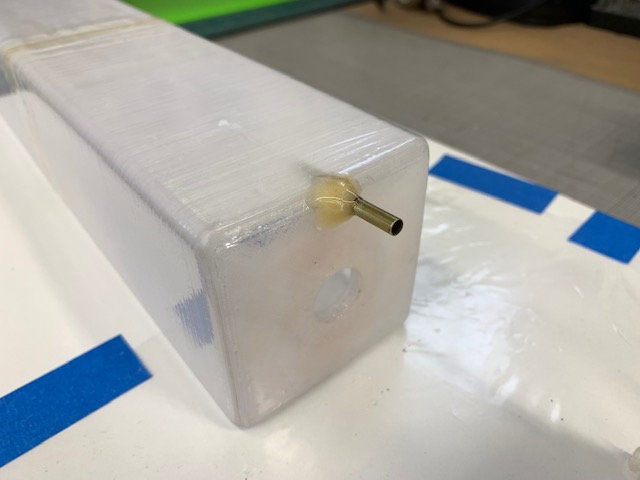
Vent tube bonded to main tank
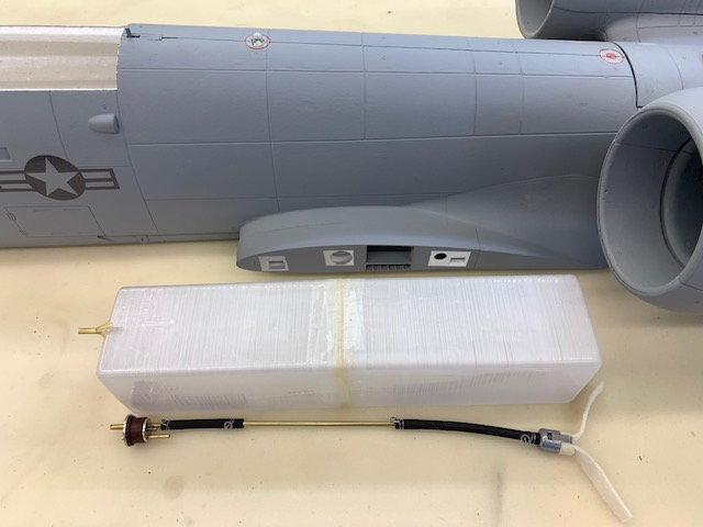
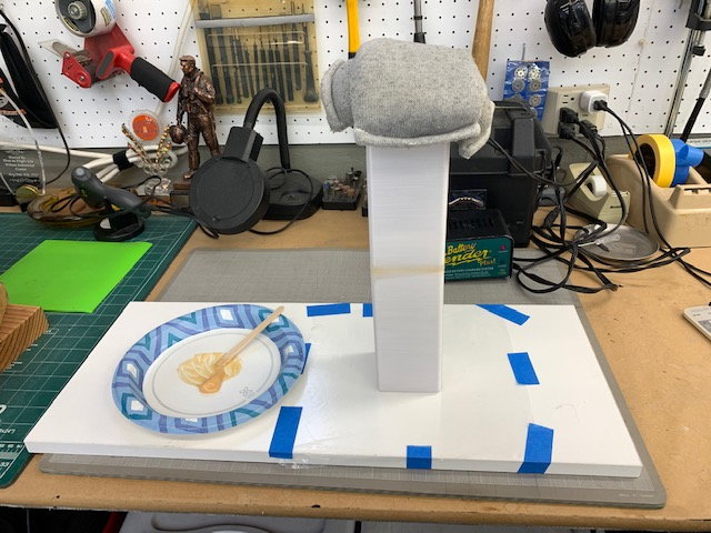
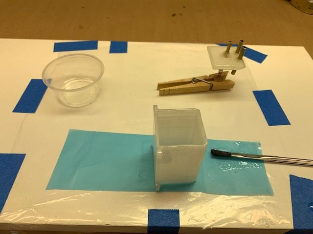
Finished tank staged next to fuse with clunk line and stopper assembled and safety wired. The clunk flops around inside very well
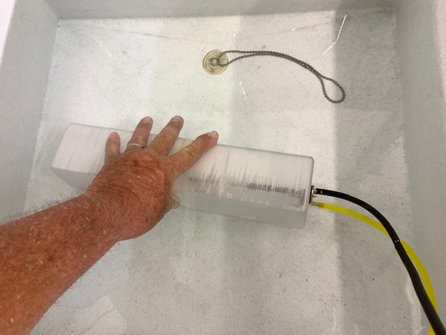
Tank assembled and leak checked under water. No bubbles!
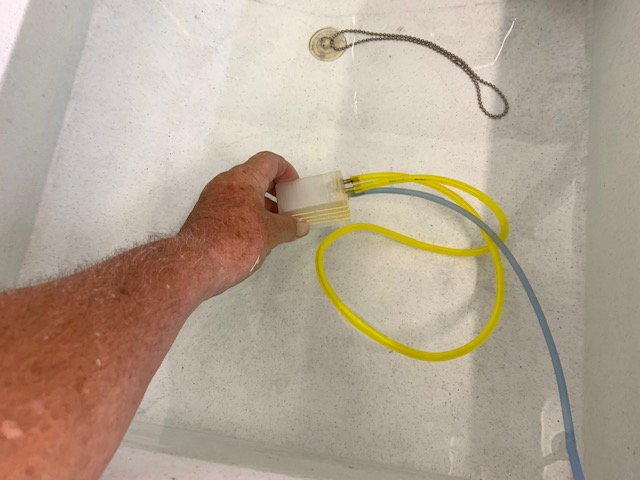
Same for air trap tank
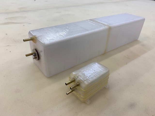
Tanks ready to install. Kevlar thread was wrapped around air trap tank to keep pump pressure from splitting seam. I had one leak and Kevlar thread solved the issue since.
Keith sent me the .stl files for the fuel tank. He calculate 1.3L or 44 oz. Plenty for the X-45. Back end printing here in translucent PETG filament. Keith loaded the fuel tank files up to Thingiverse so anyone could download and use them. Thanks Keith!
https://www.thingiverse.com/thing:5422922
Front end off printer. Designed for a standard Dubro stopper
Tank parts staged beside fuse
Two baffles were printed and installed to prevent excess sloshing in the long tank
Winged felt clunk used...I've used these in all my foamy conversions and they suck out all of the fuel
Tank hardware and baffle layout. Baffles were installed on right edge of the blue tape. The rear end has a little more space for the clunk to flop around in
Baffles were tacked in with thin CA
Tanks coated on inside with laminating epoxy. I used West Systems. Bent brush was to make sure the epoxy got everywhere behind the baffles. Sharpened coat hanger wire stands held the tank halves up during cure
After inside cure the tank seam edges were sanded and then bonded together with thickened epoxy and allowed to cure. Then the joint was wrapped with two layers of glass tape and the outside was coated with epoxy and allowed to cure. A single coat hanger wire up the center held the tank up during cure (sorry no pic)
AIr trap tank parts printed and brass tubes and filter pickup installed. Keith also loaded the air trap tank on to Thingiverse. There are two versions, one with pump mounting lugs for the K-45 pump on top and one with no lugs on top. This one is with out the pump lugs:
https://www.thingiverse.com/thing:4305344
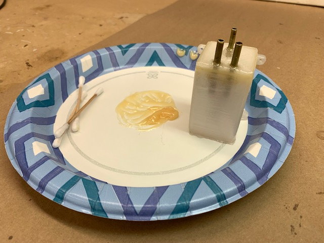
AIr trap tank coated with epoxy inside and out. Tank body sitting on a piece of perforated release film with peel ply underneath
Air trap tank bonded together with thick epoxy
Vent tube bonded to main tank
Finished tank staged next to fuse with clunk line and stopper assembled and safety wired. The clunk flops around inside very well
Tank assembled and leak checked under water. No bubbles!
Same for air trap tank
Tanks ready to install. Kevlar thread was wrapped around air trap tank to keep pump pressure from splitting seam. I had one leak and Kevlar thread solved the issue since.
Last edited by Viper1GJ; 07-06-2022 at 09:34 AM.
07-05-2022, 05:23 PM
#24
Thread Starter
My Feedback: (20)
Pipe mounting
Some final adjustments made with drum sander to allow pipe to be installed from turbine hatch with bell mounted
A small radius needed to allow pipe to slip in the tail
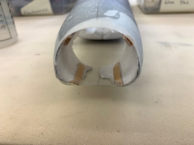
Four plywood pipe standoffs taped in place
Stand off positions marked on top and bottom
Standoff epoxied in place
Front ends beveled to allow pipe to slip in easier
Standoff cured ready for trimming
Standoff marked and trimmed with sanding drum
Bottom fiberglass part dry fit
Bottom fiberglass shell epoxied in place
Top fiberglass shell epoxied in place
Tape removed
The gap between the bottom foam parts was filled with thick epoxy and two layers of fiberglass cloth to give it strength
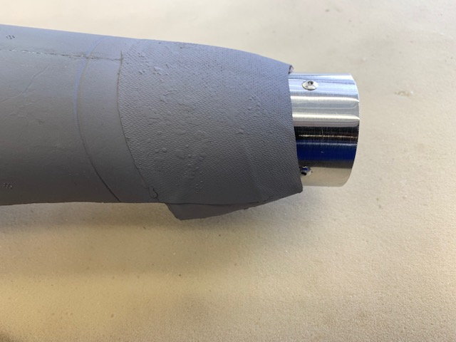
Primer applied
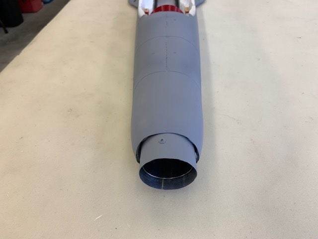
Foam filler applied and sanded. 3 more coats of primer applied and sanded. Primer applied to aft end of pipe.
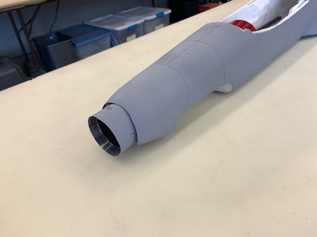
Came out ok
Some final adjustments made with drum sander to allow pipe to be installed from turbine hatch with bell mounted
A small radius needed to allow pipe to slip in the tail
Four plywood pipe standoffs taped in place
Stand off positions marked on top and bottom
Standoff epoxied in place
Front ends beveled to allow pipe to slip in easier
Standoff cured ready for trimming
Standoff marked and trimmed with sanding drum
Bottom fiberglass part dry fit
Bottom fiberglass shell epoxied in place
Top fiberglass shell epoxied in place
Tape removed
The gap between the bottom foam parts was filled with thick epoxy and two layers of fiberglass cloth to give it strength
Primer applied
Foam filler applied and sanded. 3 more coats of primer applied and sanded. Primer applied to aft end of pipe.
Came out ok
07-06-2022, 01:12 AM
#25

QUOTE=Viper1GJ;12734041]3D printed fuel and air trap tanks[/QUOTE]
Great going!! When you find the PETG leaking try woodfil PLA and infuse it with epoxy. The wood filled print turns out porous and soaks up epoxy, becomes sort of a composite part, really neat. I use laminating epoxy heated with a hot air gun to make it even thinner.
Keep it up!
https://colorfabb.com/woodfill-the-original?gclid=Cj0KCQjw5ZSWBhCVARIsALERCvz6SOJ9sO_ gjR1awZrLnE8OmcmxhAA0ffkcN_7rPsJqLyaqSTuzL2waAmXsE ALw_wcB
The following users liked this post:
Viper1GJ (07-06-2022)