


Nick’s TopRC L-39 build thread
 08-08-2022, 05:28 PM
#1
So this will be my first build thread since building my scale 1:6 Scale J-10 Vigorous Dragon Build back in 2012. This thread will take a while to complete, but it will be thorough (see previous build thread - 1:6 Scale J-10 Vigorous Dragon Build ).
Here are the manufacturer specs for the TopRC L-39:
Length: 2555mm / 101"
Wingspan: 1991mm / 78"
Flying Weight: ~16 kg / ~35 lbs
Turbine: 14-18kg /30-39lbs
Min. 11 Servos required
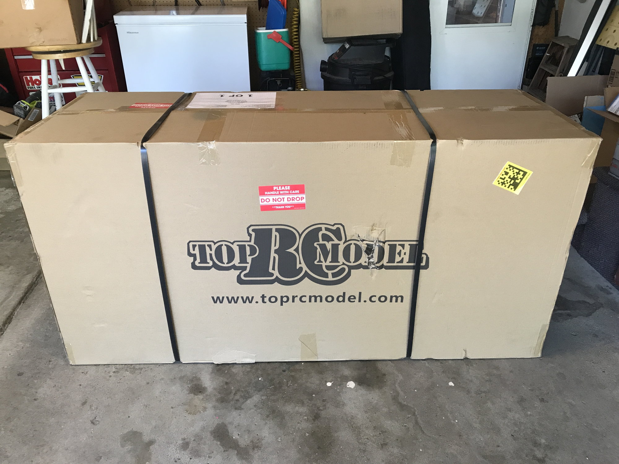
It is distributed by Gator RC and comes with TRCM Electric Retracts. My Albatros arrived on August 5th.
Here are the manufacturer specs for the TopRC L-39:
Length: 2555mm / 101"
Wingspan: 1991mm / 78"
Flying Weight: ~16 kg / ~35 lbs
Turbine: 14-18kg /30-39lbs
Min. 11 Servos required
It is distributed by Gator RC and comes with TRCM Electric Retracts. My Albatros arrived on August 5th.

The following users liked this post:
paulhat (08-27-2022)
08-08-2022, 05:34 PM
#2
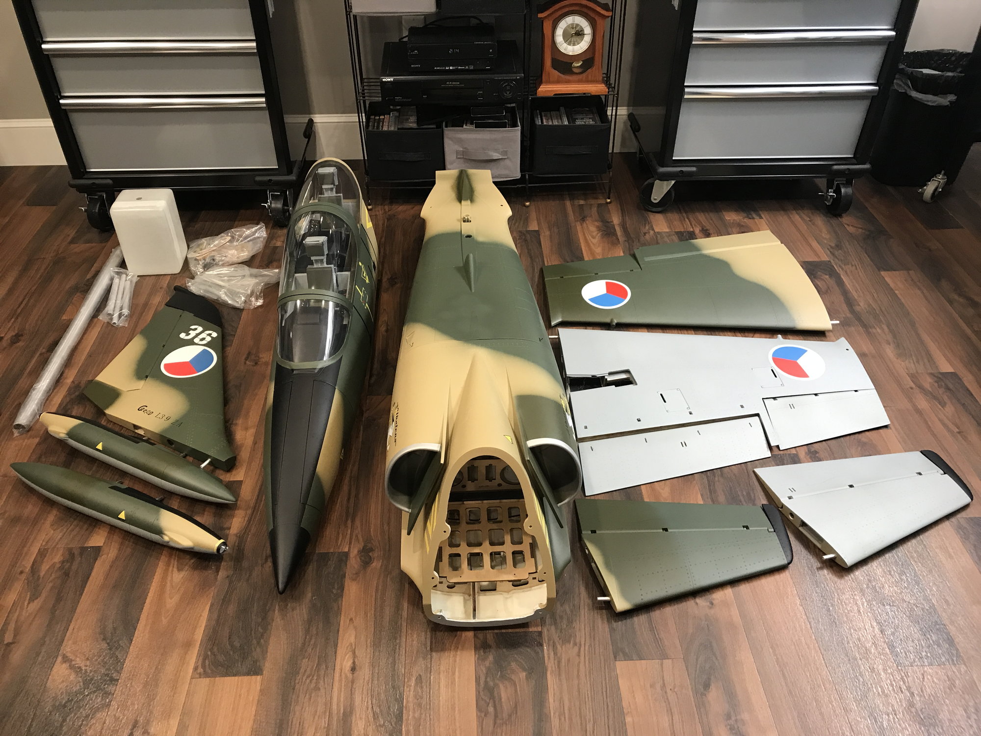
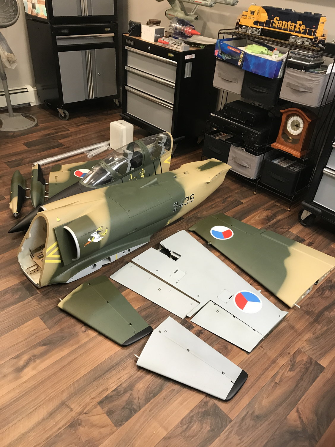
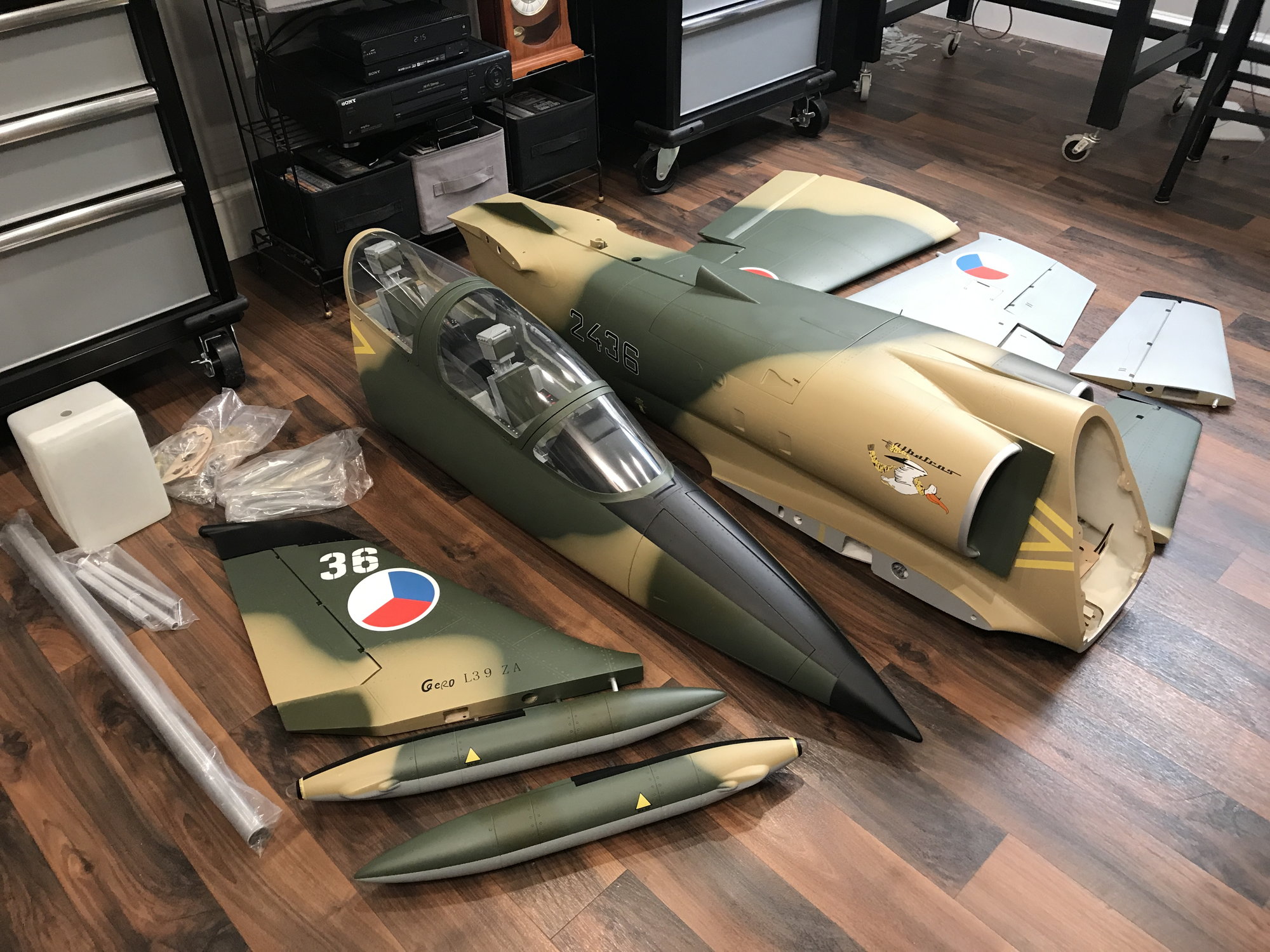
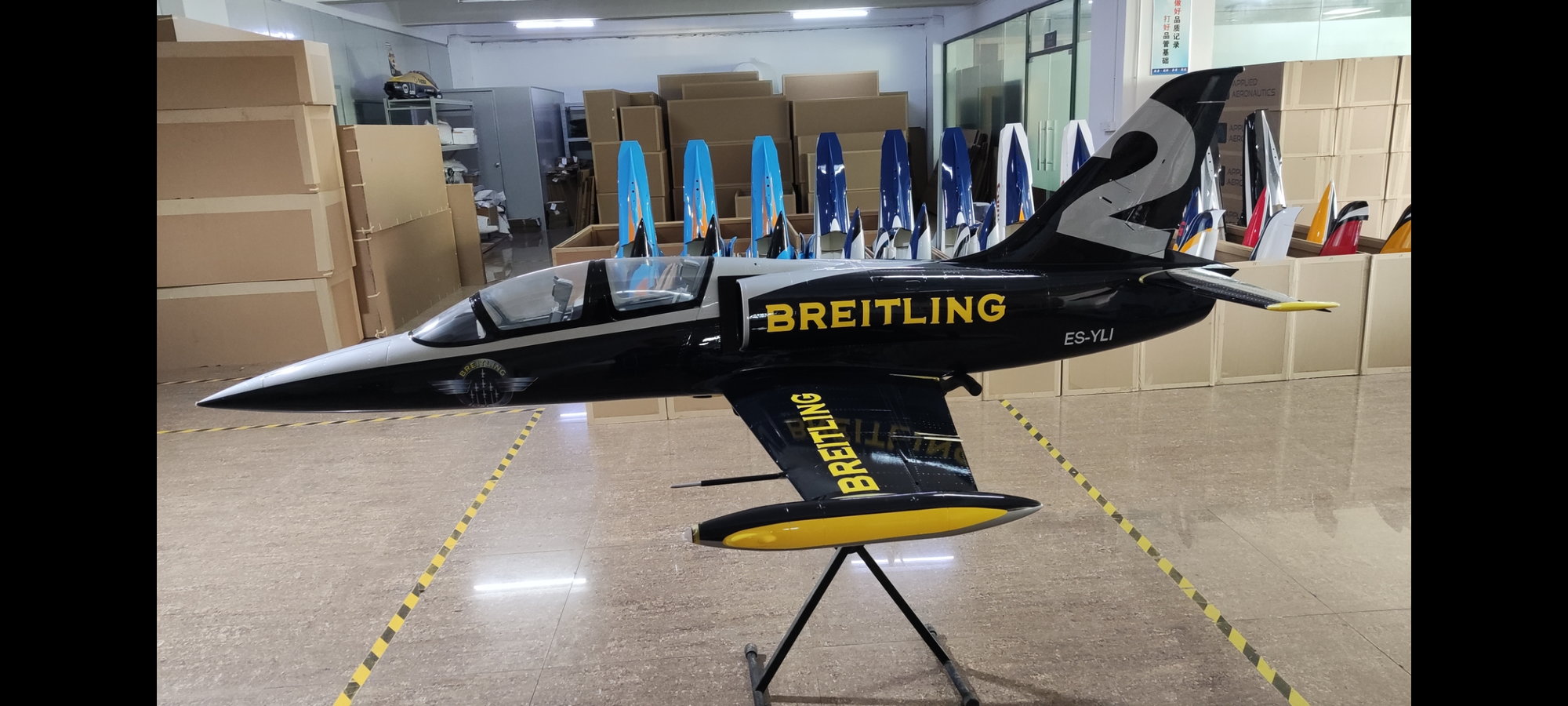
So here are some pictures of the L-39 as delivered. As you might guess, the paint is impeccable.
Here are the weights of the various components:
Hardware & misc parts supplied = 1lb 2oz
Aluminum wing, stab, rudder tubes = 1lb 3oz total
Fiberglass fuel tank = 8.6oz | Capacity = 160oz Jet-A
Cockpits = 1lb total
Nose section = 3lb 11oz
Tail section = 9lb
Rudder = 15.5oz
Stabs / Elevators = 1lb 4oz total
Tip tanks = 1lb 2oz total
Wings = 4lb 8oz total
Retracts, struts, wheels, and brakes = 3lb 15oz total
Grand total as delivered = 28lbs 1oz
Last edited by Nick Yuhasz; 08-08-2022 at 05:37 PM.
The following users liked this post:
Sky Toys (08-13-2022)
08-08-2022, 06:08 PM
#3
One of the first things I inspect on new jets is how the retract plates are secured. As you can see in two photos, the retract mounting ply is very secure including triangle stock used at joints.
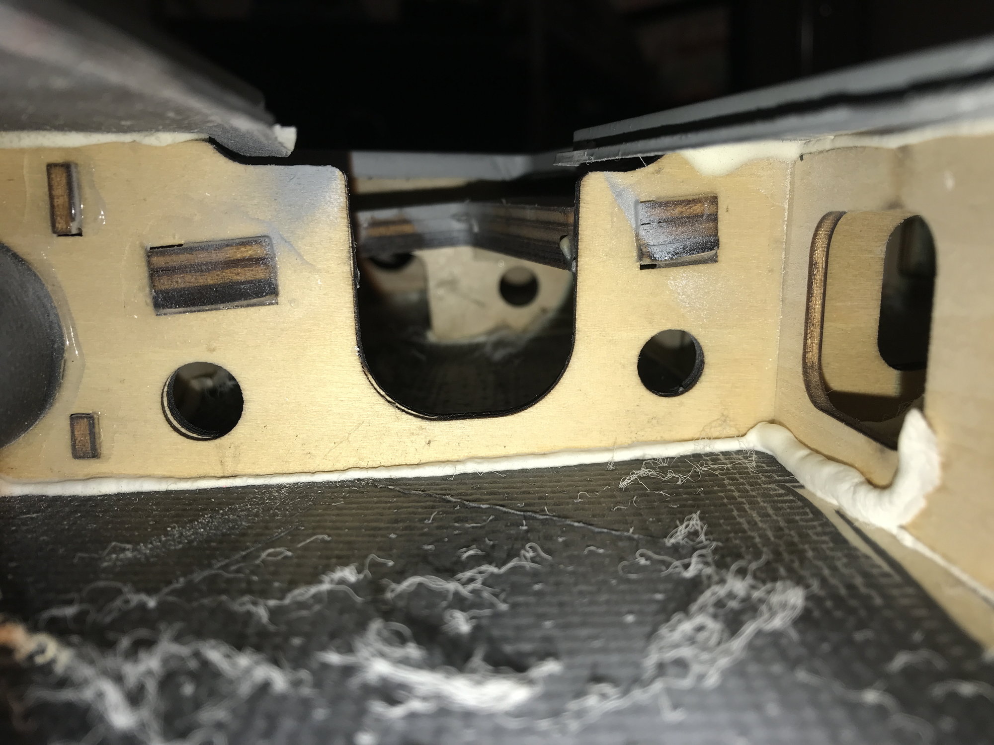
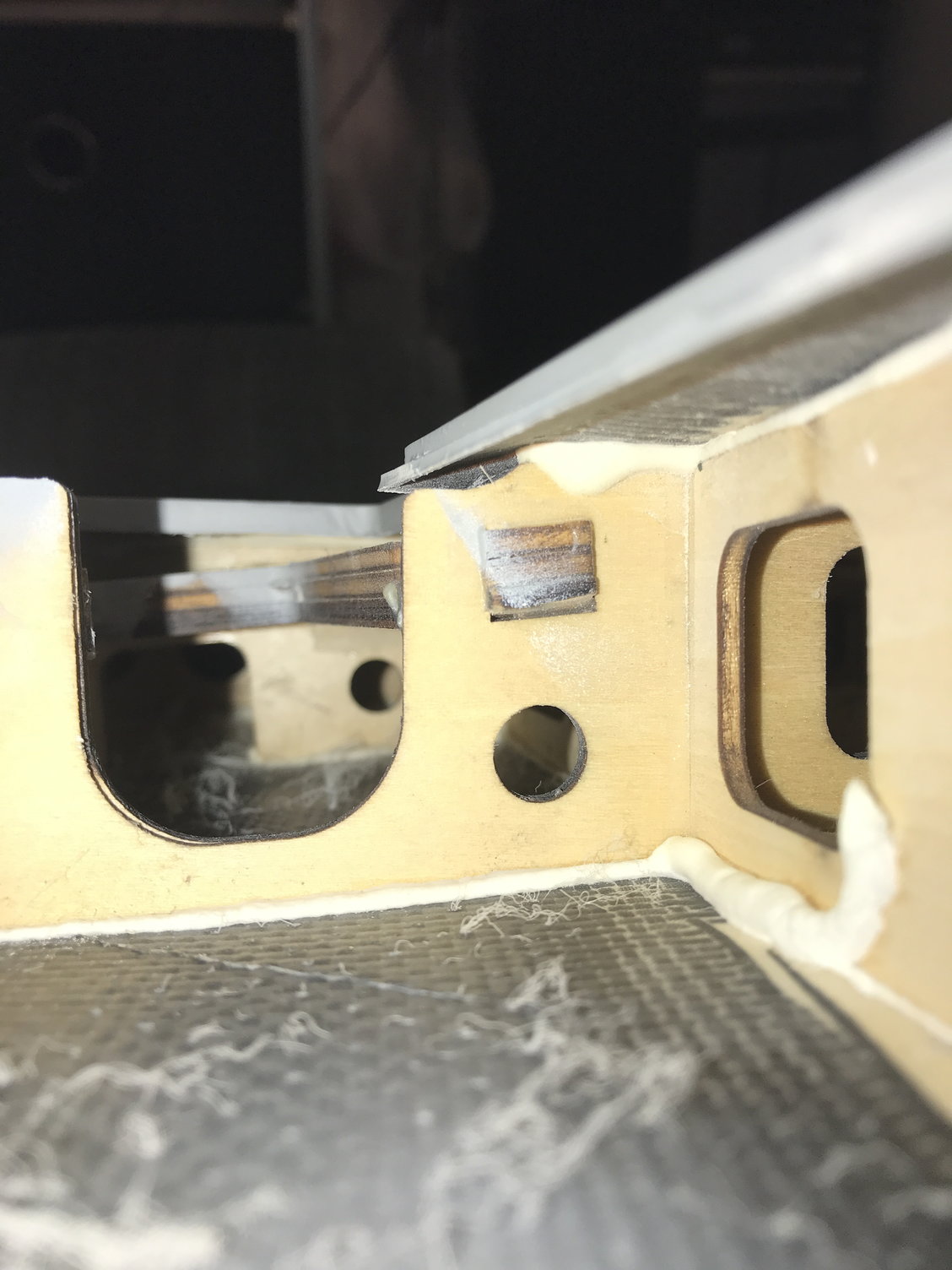
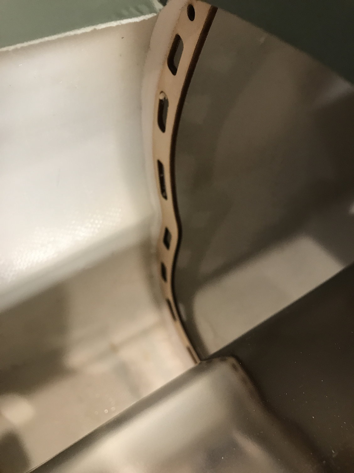
Next is a pic of how one of the bulkheads is glued – adequate glue and very clean joint.
Picture of engine access hatch and supplied thrust pipe.
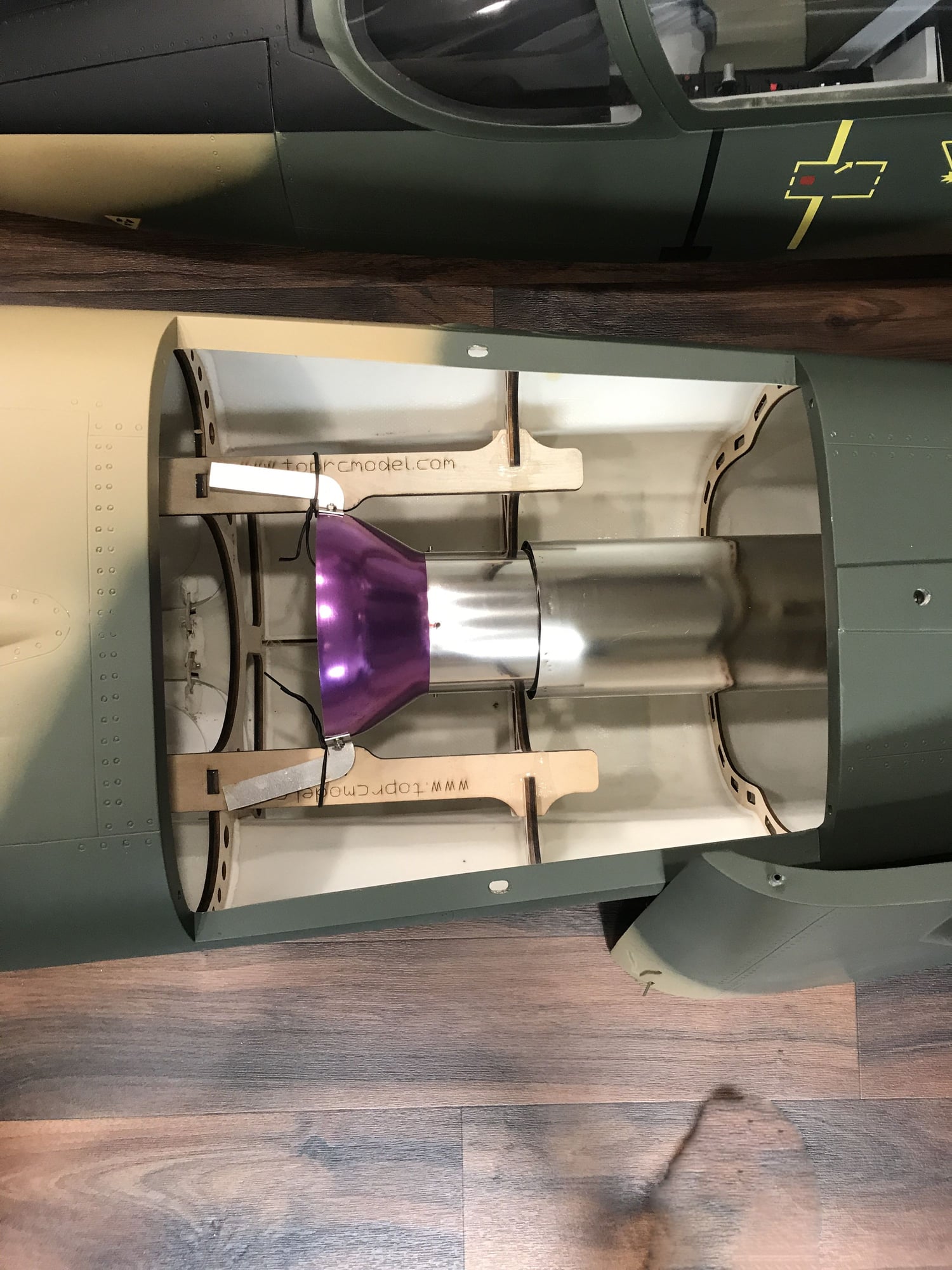
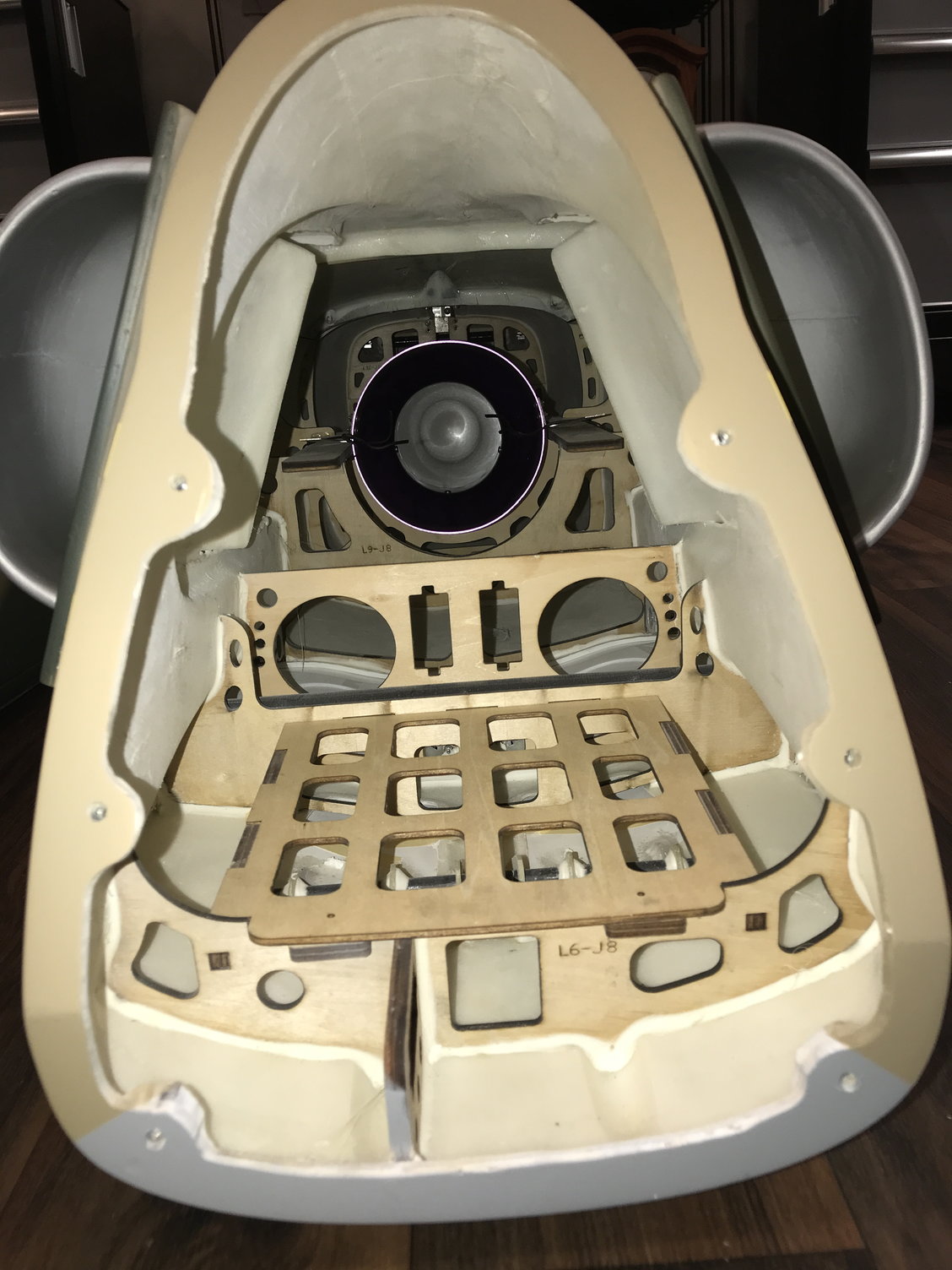
View into the rear section of the fuse.
Pic of air / speed brakes and gear doors.
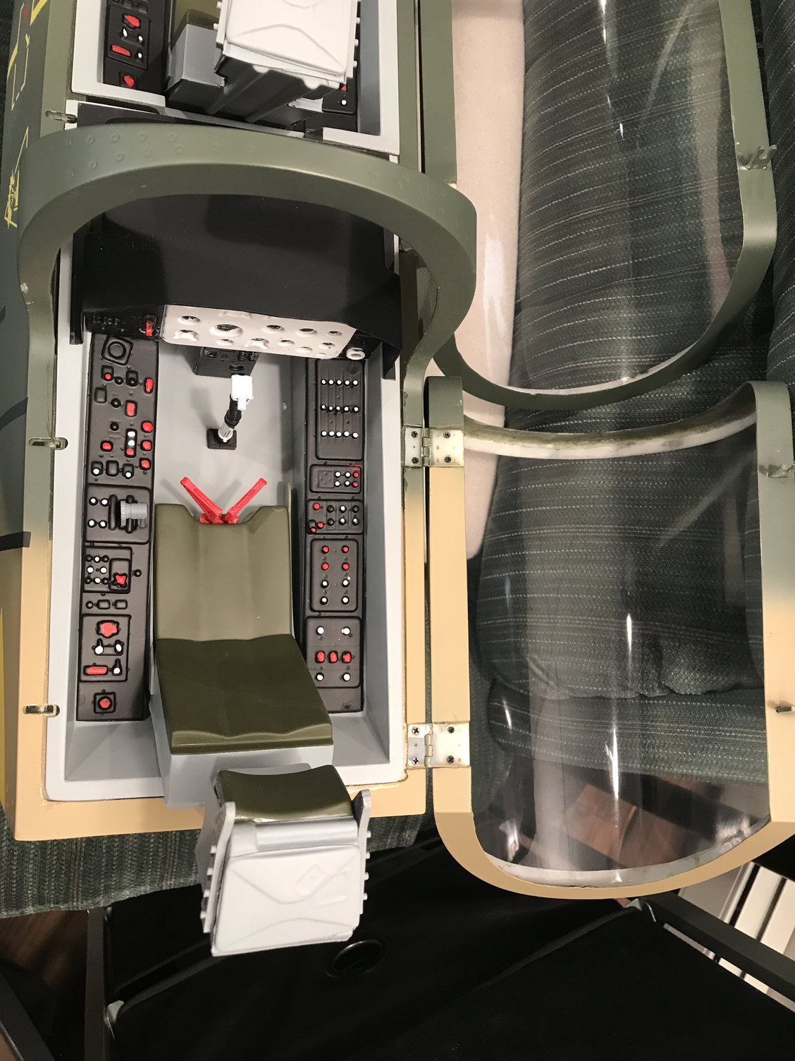
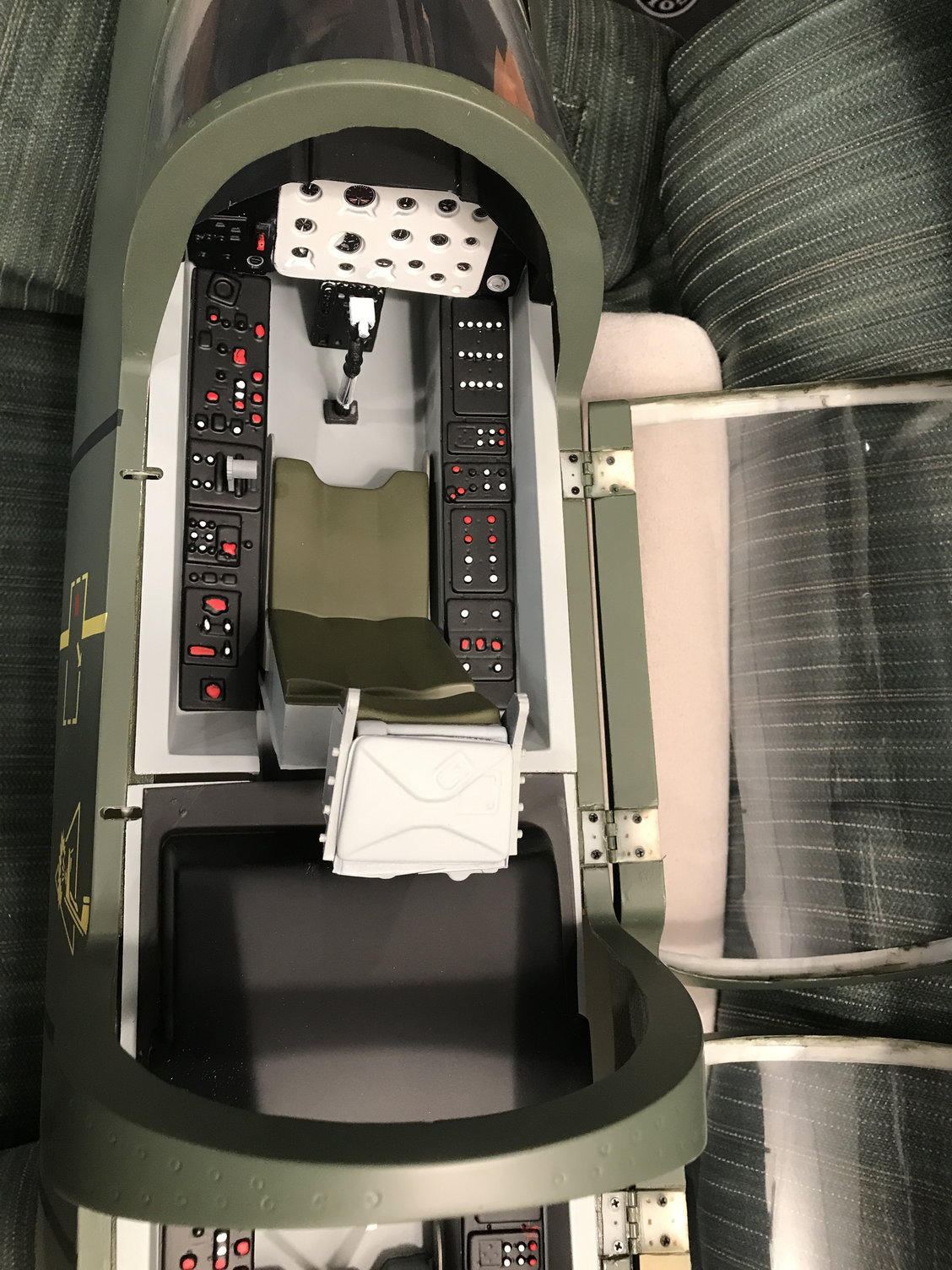
Pictures of the supplied front and rear cockpits – frames are fiberglass and components (seat, panels, etc) seem to be styrene. Acceptable quality and appearance.
More to come………..
Next is a pic of how one of the bulkheads is glued – adequate glue and very clean joint.
Picture of engine access hatch and supplied thrust pipe.
View into the rear section of the fuse.
Pic of air / speed brakes and gear doors.
Pictures of the supplied front and rear cockpits – frames are fiberglass and components (seat, panels, etc) seem to be styrene. Acceptable quality and appearance.
More to come………..
Last edited by Nick Yuhasz; 08-09-2022 at 03:05 AM.
08-09-2022, 03:00 AM
#4
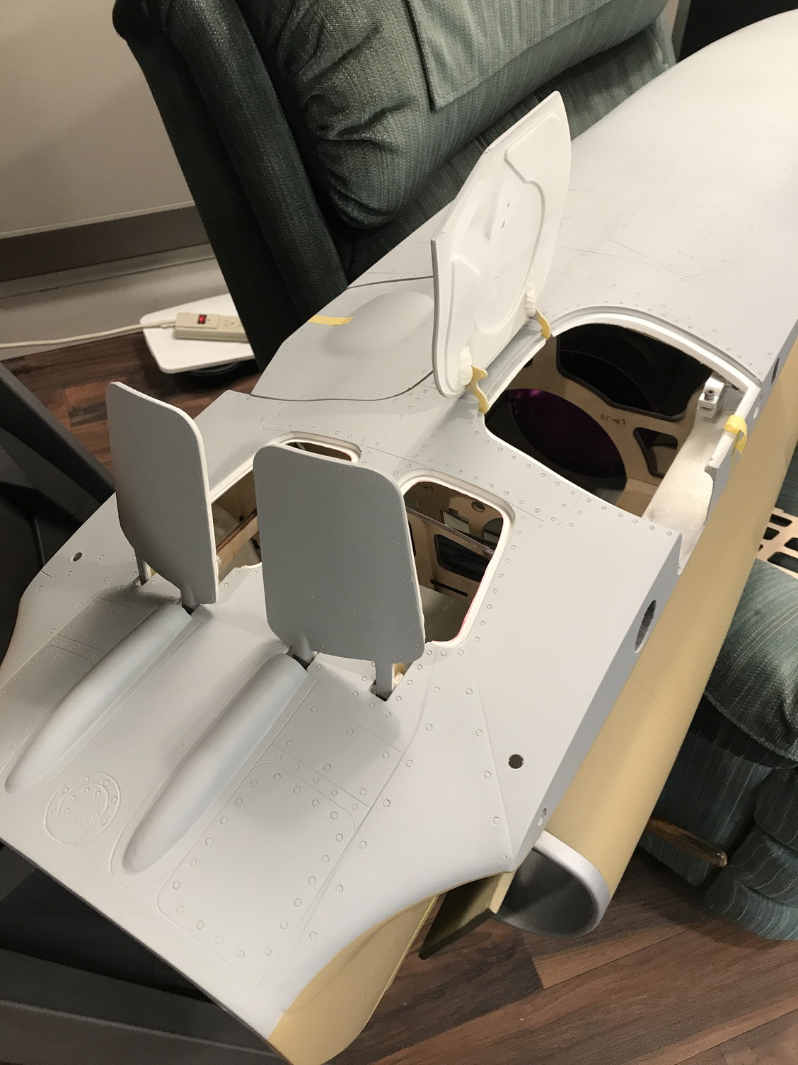
The next picture depicts a clever, hidden canopy latch system. This mechanism is similar to one used in the CARF L-39. The spring loaded, sliding rod secures both canopies. It is activated by pulling a wire loop located in the nose.
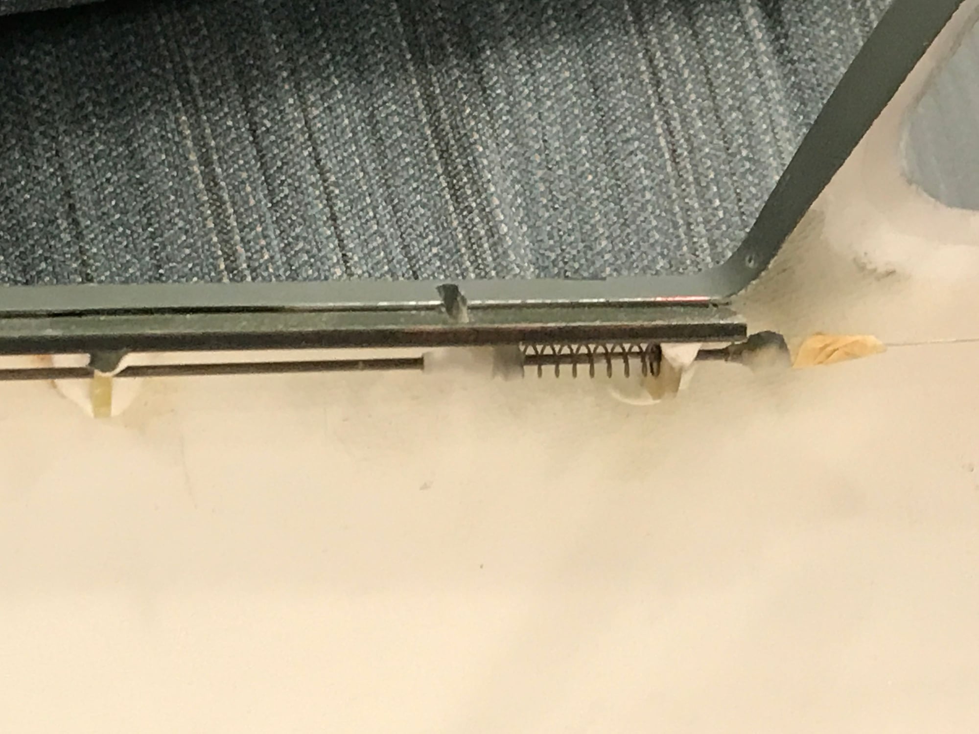
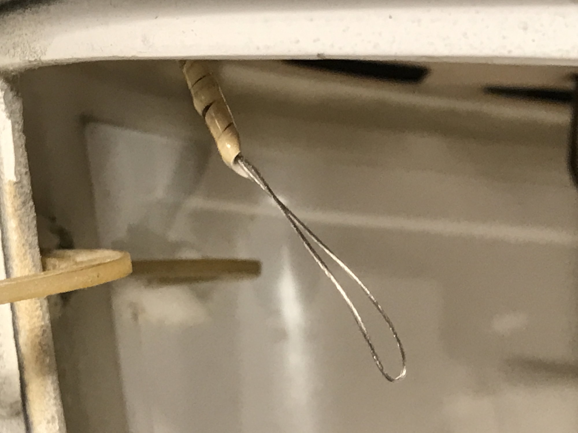
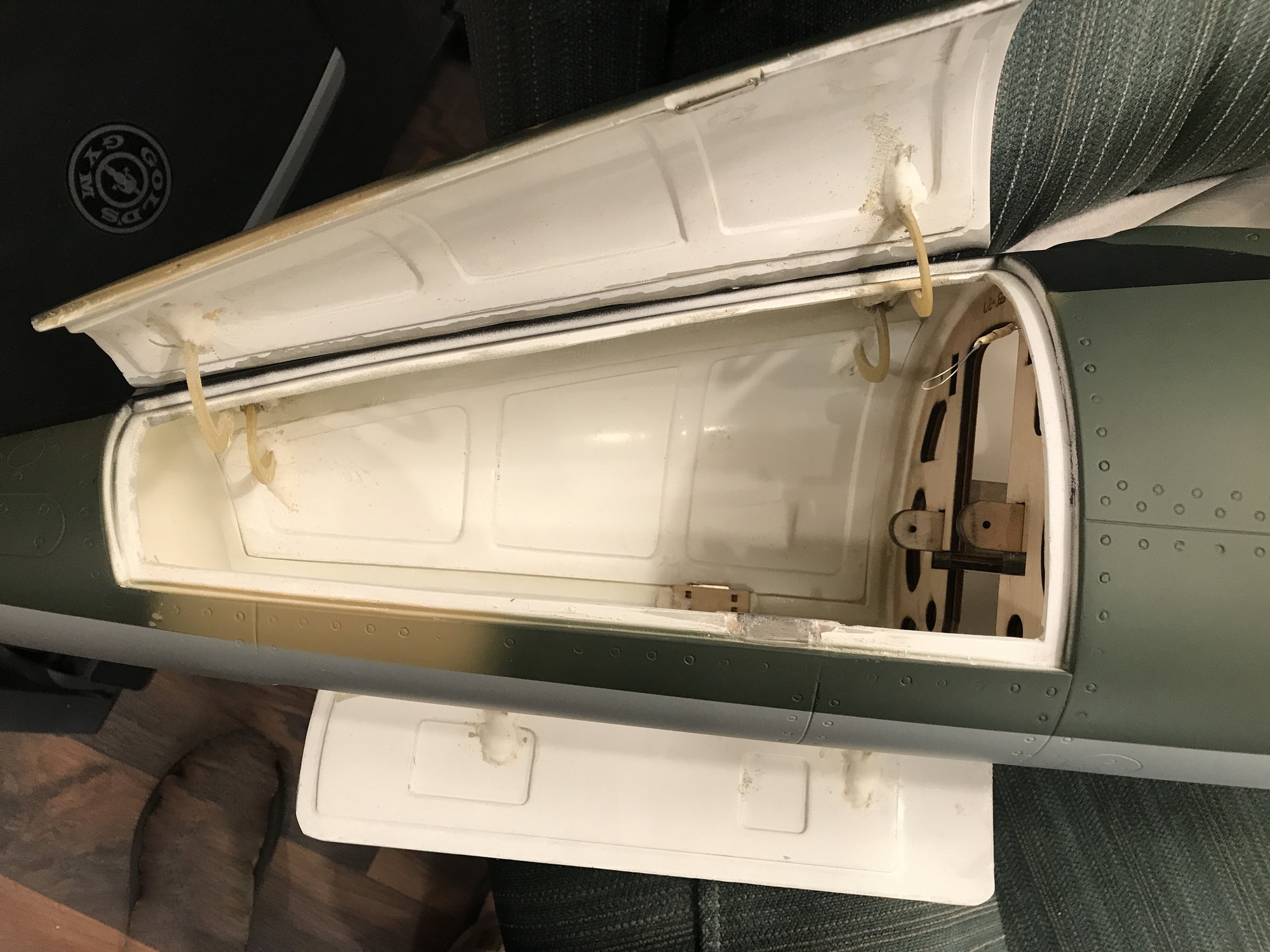
Access to the nose area and the canopy latch release is reached by opening one of two hatches in the nose. The hatches are held closed by magnets, again similar to the CARF L-39.
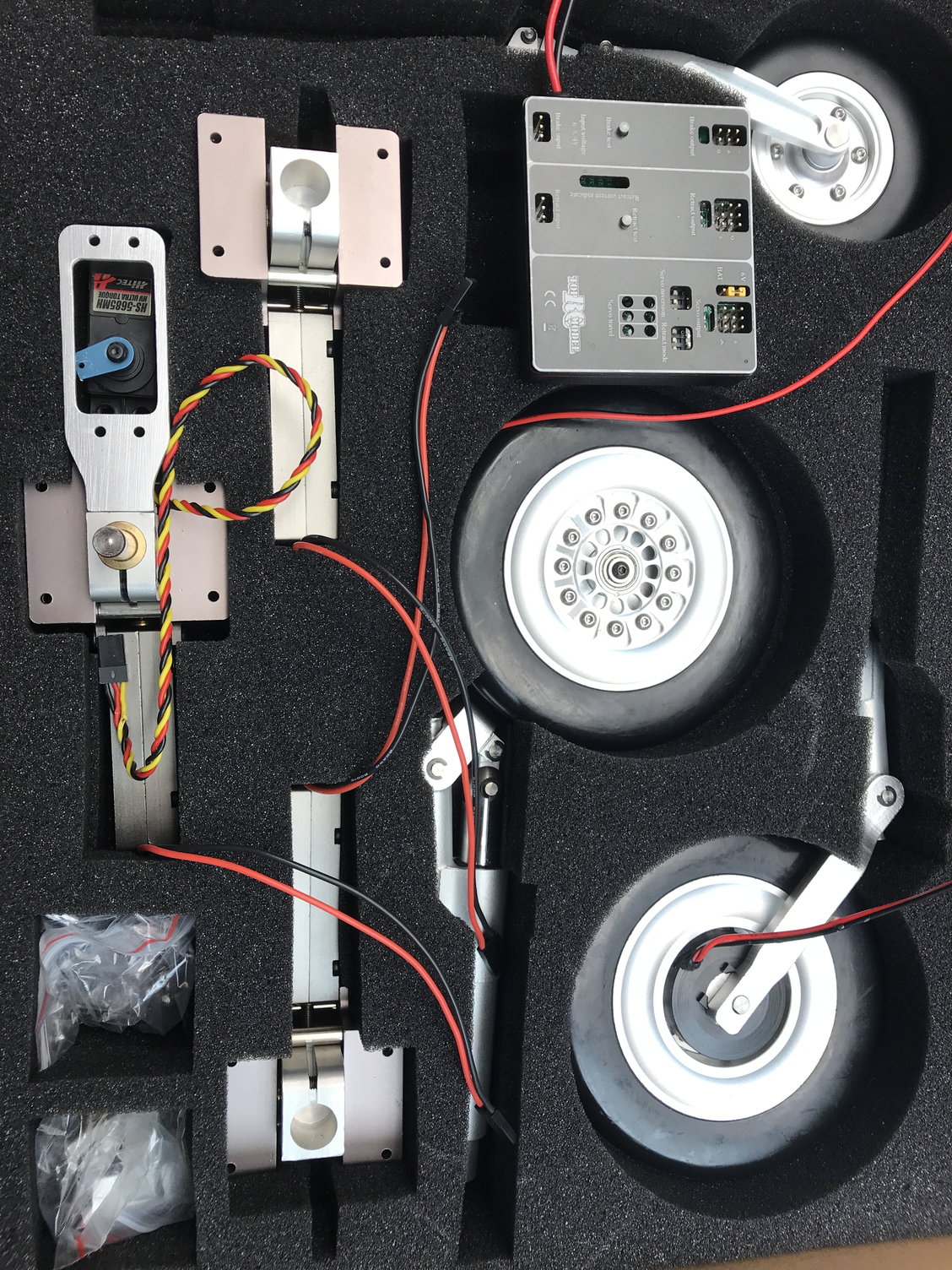
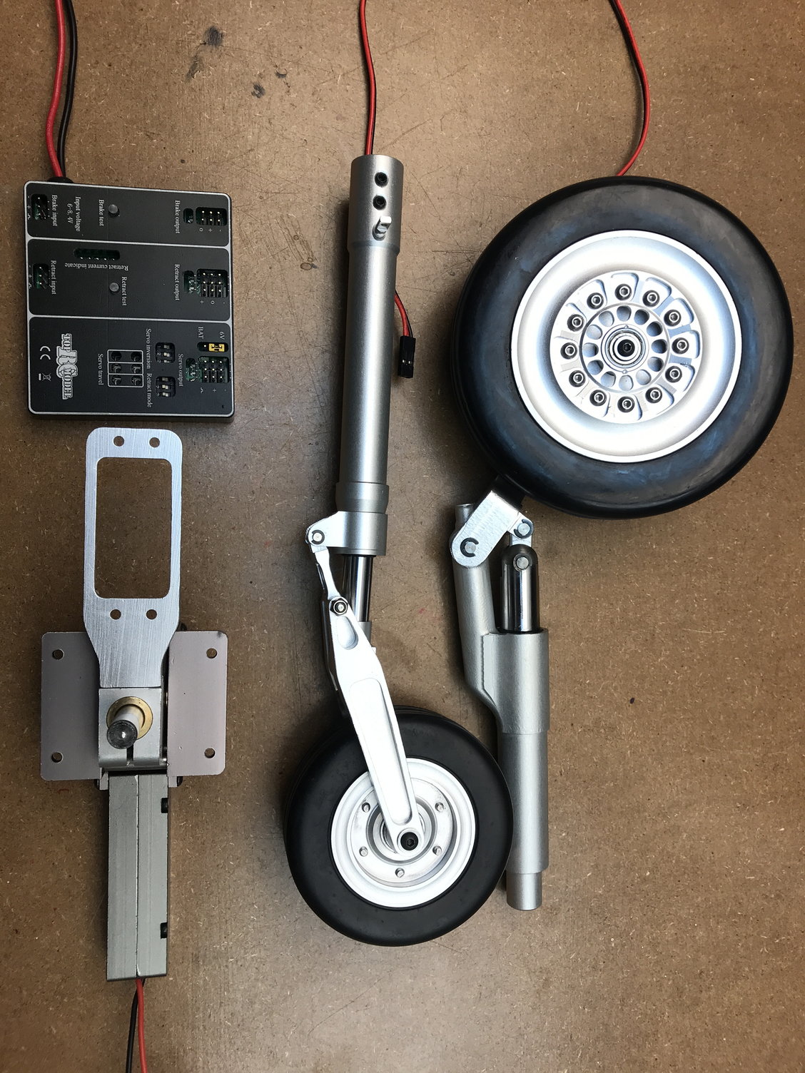
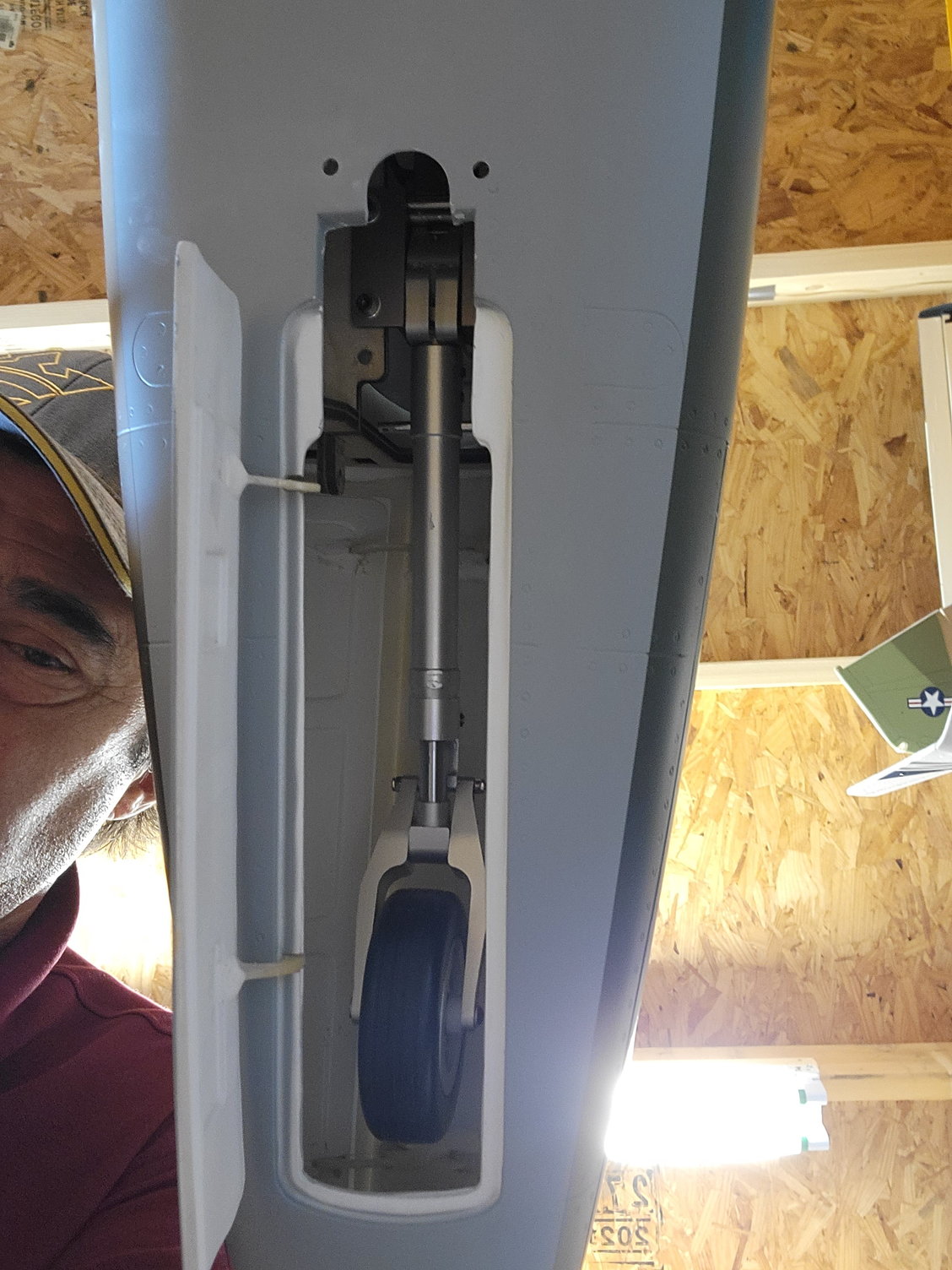
Finally, pics of the included electric retracts, struts, wheels, and brakes. The model is also supplied with a control unit / sequencer for the retracts, servo driven gear doors, and brakes.
I plan on adding lights which are left to the purchaser to supply.
At this point, the cost of the large aircraft with the apparent quality supplied and everything included appears to be a bargain. Only time will tell.
More to come………..
Access to the nose area and the canopy latch release is reached by opening one of two hatches in the nose. The hatches are held closed by magnets, again similar to the CARF L-39.
Finally, pics of the included electric retracts, struts, wheels, and brakes. The model is also supplied with a control unit / sequencer for the retracts, servo driven gear doors, and brakes.
I plan on adding lights which are left to the purchaser to supply.
At this point, the cost of the large aircraft with the apparent quality supplied and everything included appears to be a bargain. Only time will tell.
More to come………..
The following users liked this post:
Sky Toys (08-13-2022)
 08-09-2022, 06:22 AM
#6
One thing I didn’t mention is that you will need to glue / Hysol the Robart style hinges for all the control surfaces. It can be time consuming as I remember. Haven’t had to do that for many years so I will need to relearn that process.
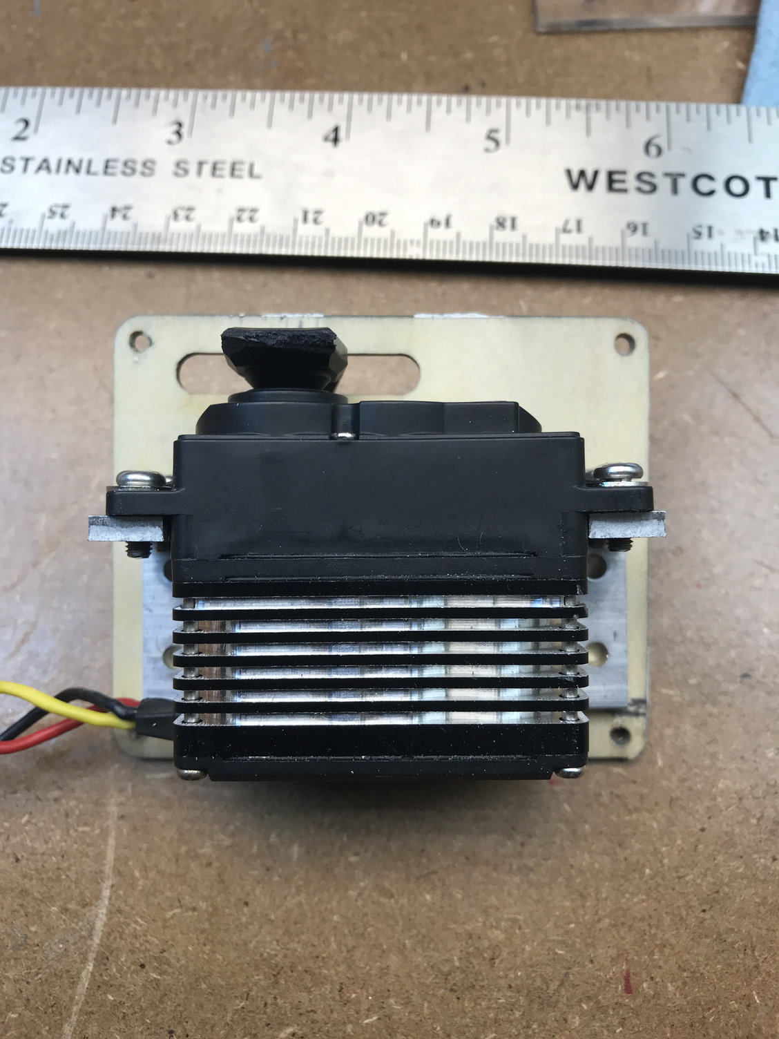
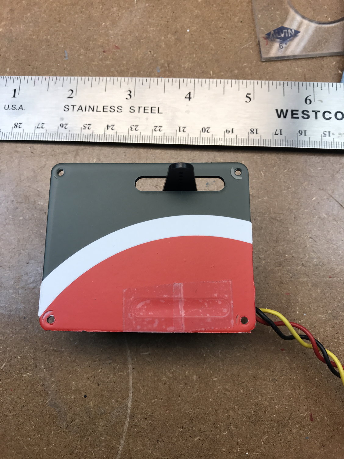
Close-up of hardware supplied – Control rods for all primary control surfaces are 2.78mm or 7/64” diameter.
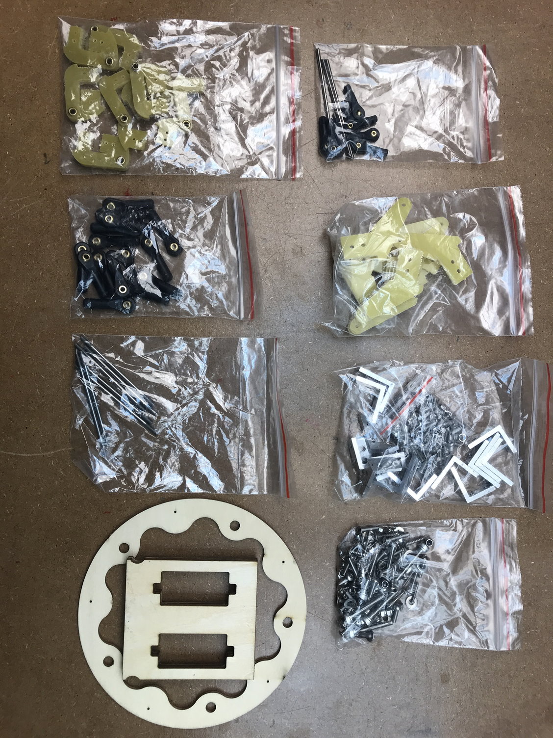
So I am planning on using Hitec HS-7955TG servos (I own a lifetime supply) on all surfaces except a HS-7980TH for the Rudder. iGyro SRS, two Futaba R6208SB Receivers with a Smart-Fly PowerExpander Competition 12 (I have this setup in all my jets). Dual A123 batteries for the receivers / servos plus an A123 ECU battery for a KingTech K-180.
More to come………..
Close-up of hardware supplied – Control rods for all primary control surfaces are 2.78mm or 7/64” diameter.
So I am planning on using Hitec HS-7955TG servos (I own a lifetime supply) on all surfaces except a HS-7980TH for the Rudder. iGyro SRS, two Futaba R6208SB Receivers with a Smart-Fly PowerExpander Competition 12 (I have this setup in all my jets). Dual A123 batteries for the receivers / servos plus an A123 ECU battery for a KingTech K-180.
More to come………..
 08-22-2022, 08:18 AM
#10

My Feedback: (4)
Join Date: Jan 2002
Location: Bartlett, IL
Posts: 41
Likes: 0
Received 0 Likes
on
0 Posts
Ok been two weeks ... any updates? You using the top rc gear and controller? Is the nose gear door a servo mechanism like the mains or is it a mechanical like the odyssey where as the gear leg comes up it closes the door and when the gear extends a spring system opens the door? Wish the hinging was skin hinges... otherwise looks nice
08-23-2022, 05:26 AM
#11
Ok been two weeks ... any updates? You using the top rc gear and controller? Is the nose gear door a servo mechanism like the mains or is it a mechanical like the odyssey where as the gear leg comes up it closes the door and when the gear extends a spring system opens the door? Wish the hinging was skin hinges... otherwise looks nice
That said, yes, I am going to use TopRC gear and controller supplied. I also plan on having a servo-driven nose gear door like the mains (not mechanical like the Odyssey). Not sure where the servo needs to get mounted in the nose yet.
Nick

 08-23-2022, 08:20 AM
#13
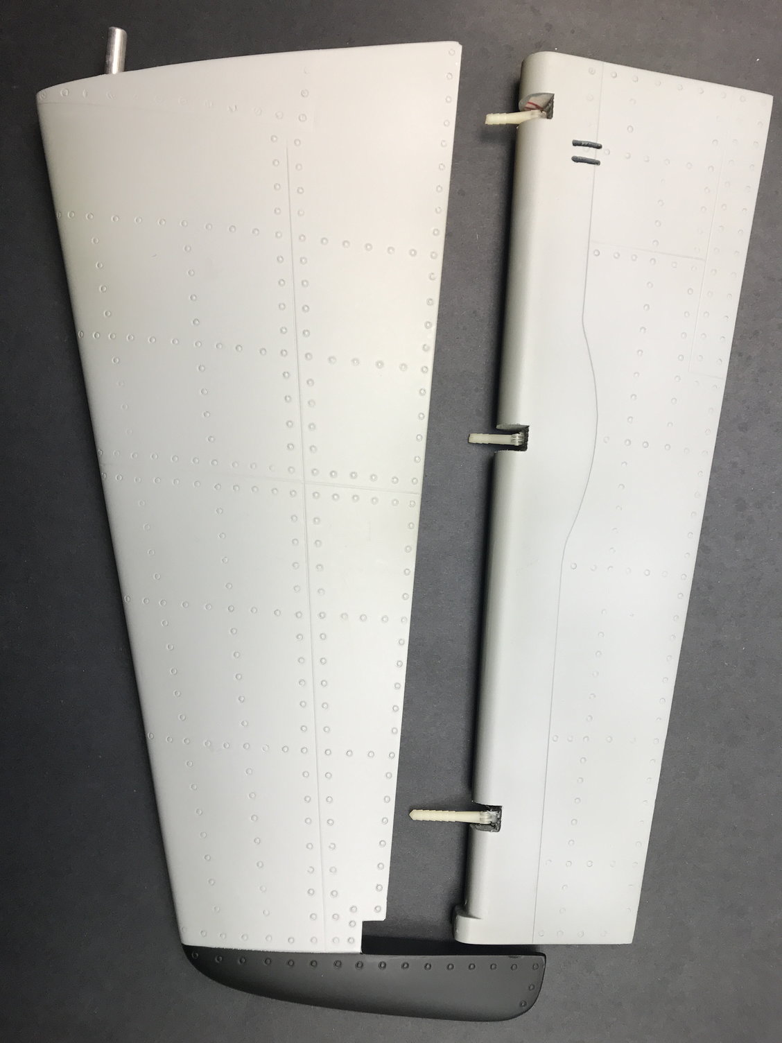
So I decided to work on an easy task to get started on the build - the rudder / fin. Well I thought it would be easy.
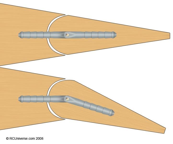
You will need to shorten the control arms that are Hysol'd into the rudder and open the slots in the rudder slightly so they will fit. Next Hysol the Robert style hinges to the rudder; note: the hinge must be tight against the cutout in the rudder so they will operate correctly once attached to the fin (see example drawing). Also, shorten the 3mm control rod by .125" on each end to fit between servo arm and control arms. Use the supplied, aluminum servo mounts to attach the servo to the servo hatch / cover.
Now for the "easy" part: I attempted to "fish" wire from the servo bay to the exit hole near the front bottom of the fin. Due to the location of the tube that accepts the aluminum locating tube that fixes the fin to the fuselage, there is no direct path for the servo wire to exit the bottom of the fin. I tried using spring wire and a small fishing lead weight to run the wire through the fin both from the servo bay and up from the bottom. I was tempted to try to drill up through the bottom of the fin, but again, no direct path to the servo bay. It took trying 1 hour per day for 4 days to successfully navigate the gauntlet! You would have thought I learned from that experience, but NO... I decided to try to fish wire for the navigation light I plan to install on the top rear of the fin. Still struggling - no joy. I will probably need to drill some exploratory holes in the fin vertical wood at the rear of the fin to see what is obstructing the fish line....
More later....
More later....
The following 2 users liked this post by i3dm:
mups53 (08-27-2022),
Nick Yuhasz (08-24-2022)
08-25-2022, 06:09 AM
#15
For those wanting to add lighting, here is what I ordered from Unilight:
Wing tip landing spotlights (2x) - 20mm Ultra-Power-Spotlight, 8Wx2,T-FUSE and lens
Fin (top rear)- 13/15mm PIN Strobe Light, 16x2W, T-Fuse (white)
Top Beacon / Strobe (not on full scale) - 13/15mm PIN Strobe Light, 16x2W, T-Fuse (red)
Wing Nav / ACL (ACL not on full scale) - DUAL11F-160x2-RNWE and DUAL11F-160x2-GNWE
The combo wing Nav / ACL are slightly longer than scale. Scale would be: DUAL9F-110x2-RTWE and DUAL9F-110x2-GTWE. I just wanted to ensure they would be bright enough so I went with the slightly longer version.
Total cost about $300 USD
More later......
The following users liked this post:
gui8 (12-05-2022)
The following users liked this post:
Nick Yuhasz (08-27-2022)
 08-29-2022, 03:42 AM
#18
Clay: Thanks for the tip on the "pull chain"! I will try that for the wing nav / ACL lighting wire.
So for all of my large jets, I perform a servo torque requirement calculation that is contained in the AMA Large Turbine Model program (I don't anticipate that this jet will need to be a LTMA jet).
Based on those calculations for an "unlimited aerobatic" jet traveling > 140 mph, here are the minimum servo torque requirements for the TopRC L-39:
Aileron - 256 oz. / in.
Elevator - 203 oz. / in
Rudder - 206 oz. / in
These calculations are based on the control surface's length, root and tip chord plus the servo arm length and control horn length. At first blush, the rudder torque seems too low for such a large fin, but the actual rudder is small compared to the aileron area. Remember these are minimums.
More later.........
The following users liked this post:
Ron S (08-29-2022)
08-29-2022, 05:52 AM
#19
Senior Member
My Feedback: (2)
Join Date: Aug 2002
Location: Longview TX
Posts: 157
Likes: 0
Received 0 Likes
on
0 Posts
Nick,
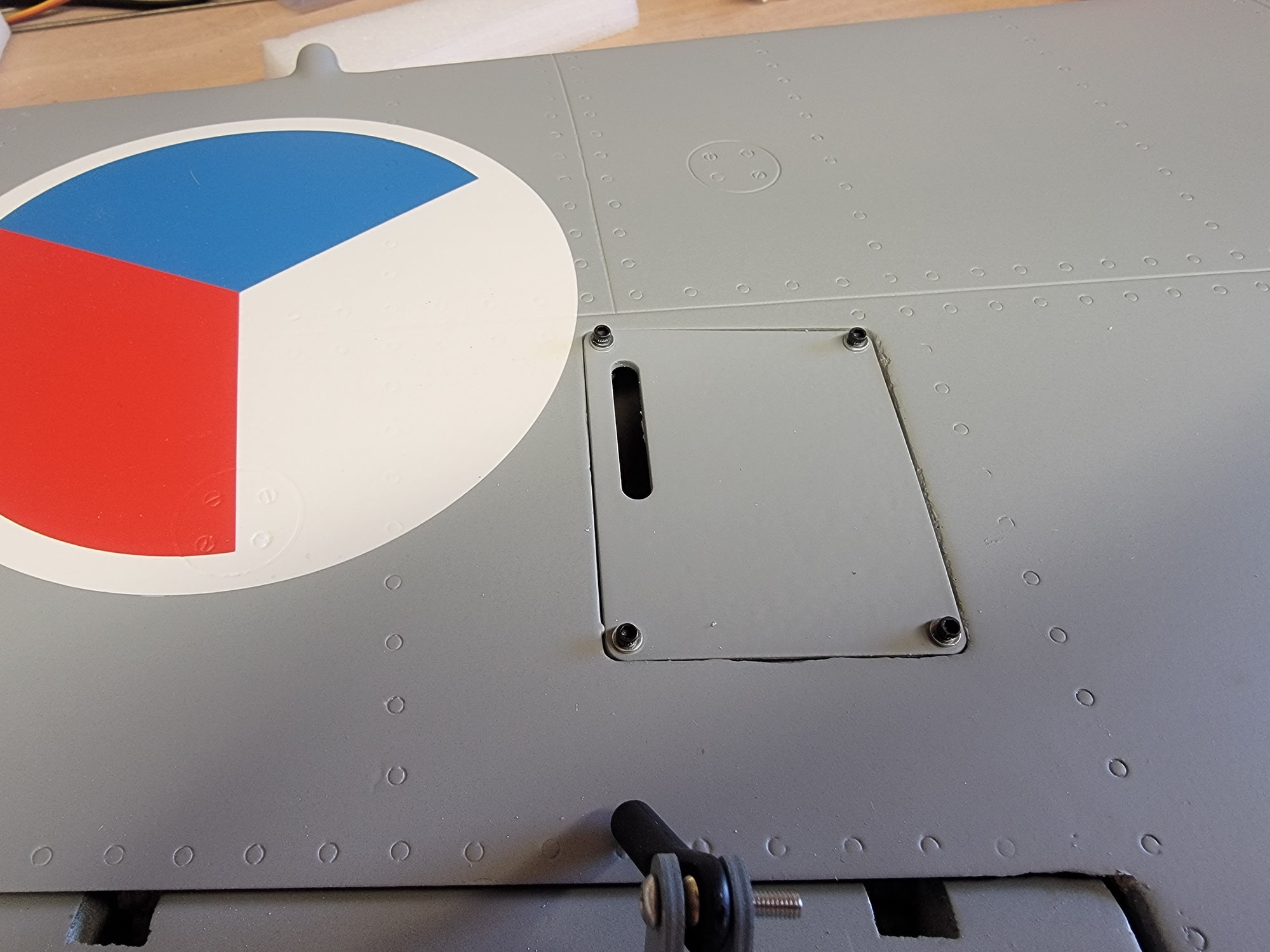
I am also currently assembling the L39, I have all the hinging done and made support struts for the 2 front hatches. I am planning on a SW170 or 190 for this bird. I currently have a Odyssey with the 170. Have you figured if the plywood square with the servo cut outs will be used, I cannot find any place for it.
Eddie
08-29-2022, 06:00 AM
#20
Nick,
I am also currently assembling the L39, I have all the hinging done and made support struts for the 2 front hatches. I am planning on a SW170 or 190 for this bird. I currently have a Odyssey with the 170. Have you figured if the plywood square with the servo cut outs will be used, I cannot find any place for it.
Eddie
Nick
Last edited by Nick Yuhasz; 08-29-2022 at 06:02 AM.
08-29-2022, 06:52 AM
#21
Senior Member
My Feedback: (2)
Join Date: Aug 2002
Location: Longview TX
Posts: 157
Likes: 0
Received 0 Likes
on
0 Posts
Yes, I wonder if was used on a prototype and then left in the package, I will upload some pics tonight. I have the retracts mounted in the wings also. The biggest change so far is that I placed 2-56 socket head screws with blind nut on all the servo hatches, the small wood screws I believe would wear over time. I did the same thing on my Odyssey and Boomerang jets and it has held up great.
Eddie
Eddie
09-01-2022, 07:54 PM
#23
Senior Member
My Feedback: (2)
Join Date: Aug 2002
Location: Longview TX
Posts: 157
Likes: 0
Received 0 Likes
on
0 Posts
Here is where I am at, the nose modification and the wings. They are ready for me to start servo installation.
Had to notch to allow the gear to retract completely.
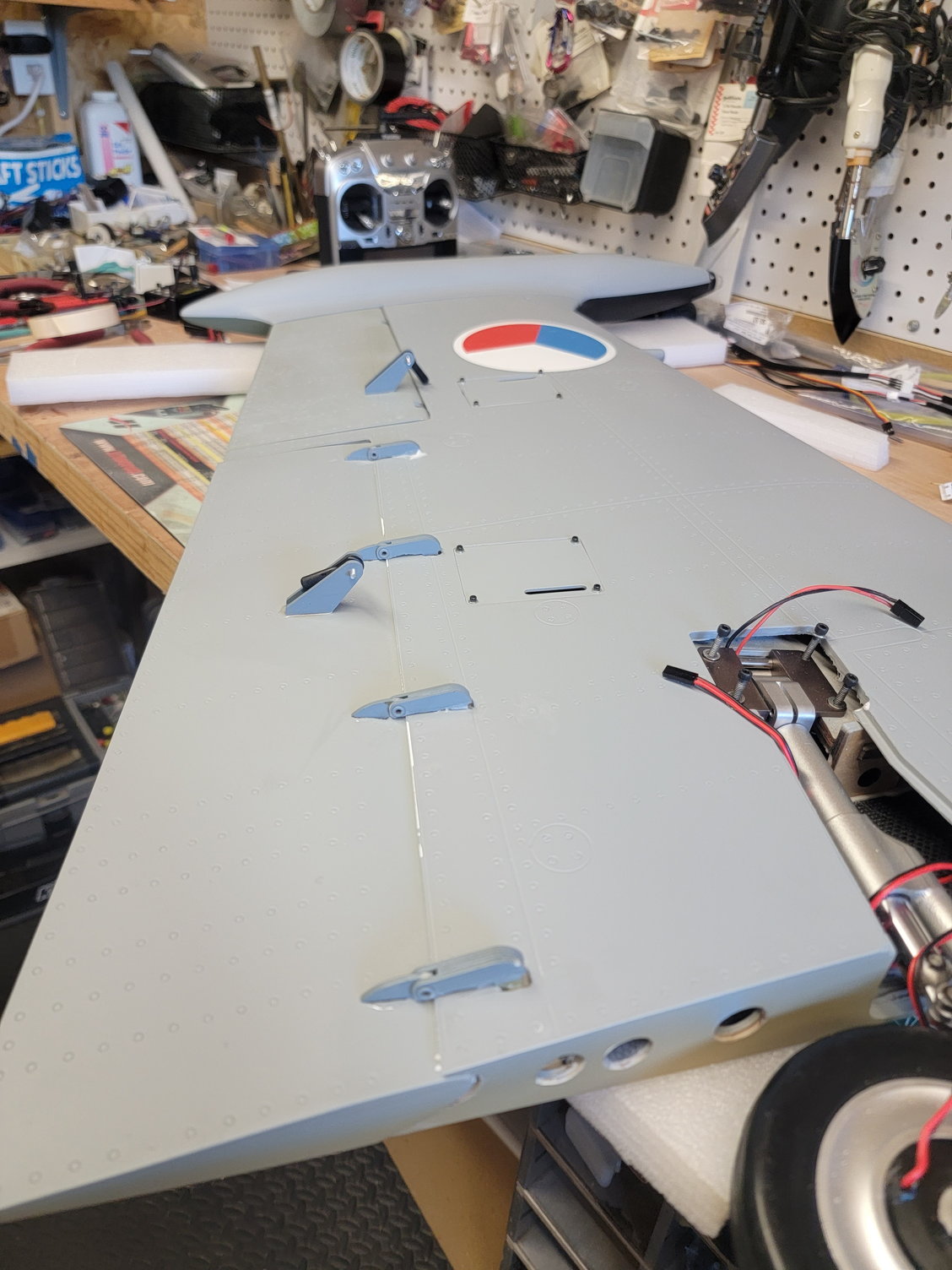
Painted horns.
Had to notch to allow the gear to retract completely.
Painted horns.
09-02-2022, 10:45 AM
#24
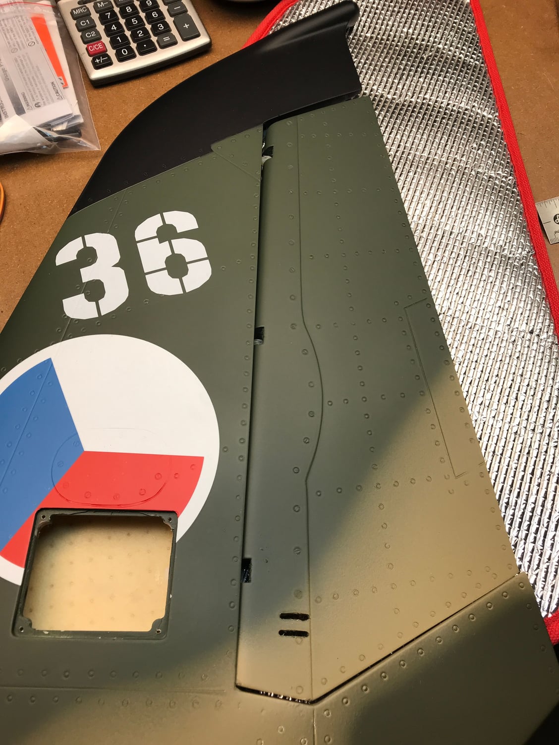
I would like to thank Cap'n Dave Murray and Eddie Bernaldez for contributing to this build thread. They are way ahead of my build and will no doubt maiden their L-39 before me.
That said, I have been busy doing some extraneous things. I decide to differentiate my L-39 from the others by painting the top of the fin, stab ends and nose Hi Vis Yellow. I located a pic of a camo (like mine) scale L-39 with this paint scheme. (Pics show the gloss Yellow that needs to have a flat coat painted soon)
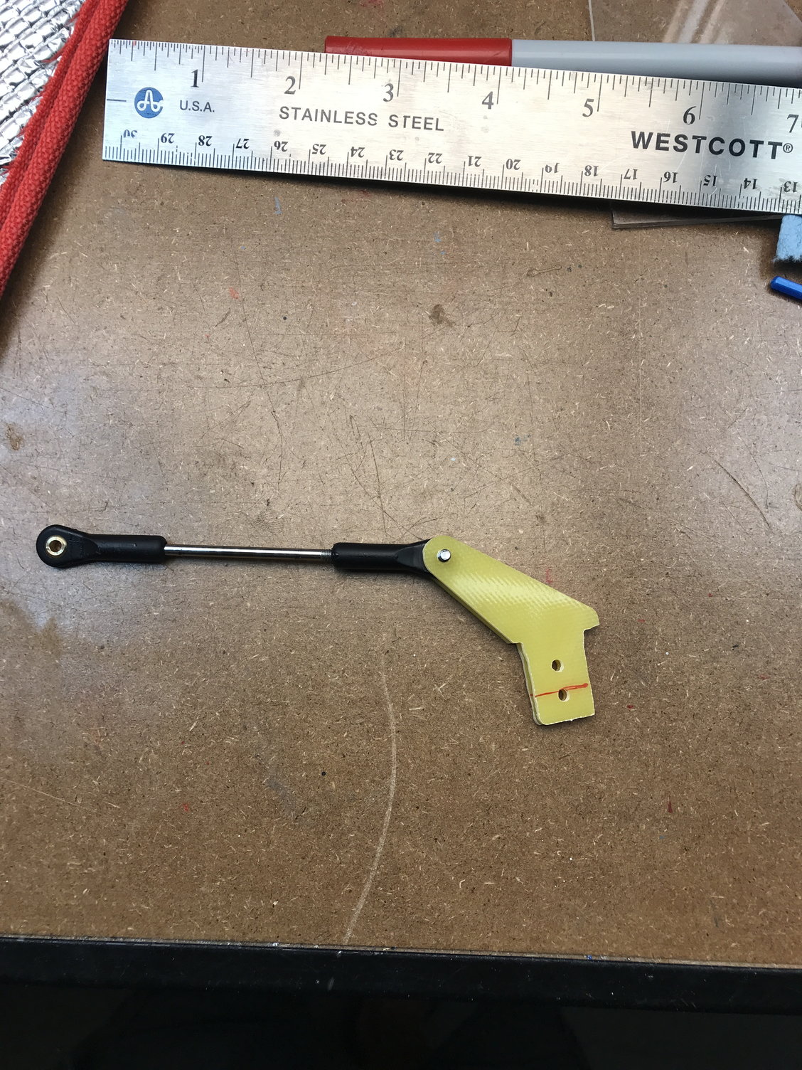
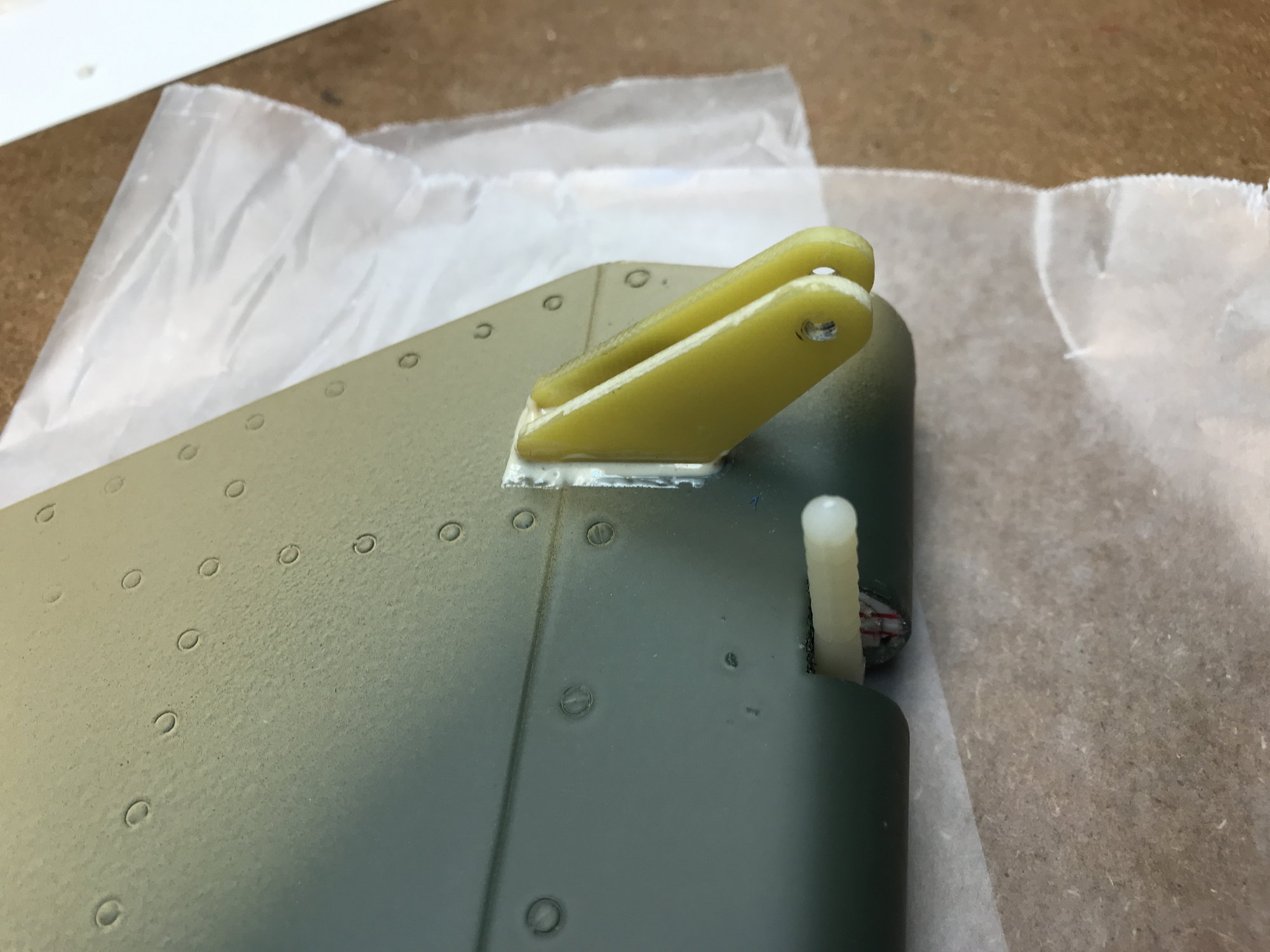
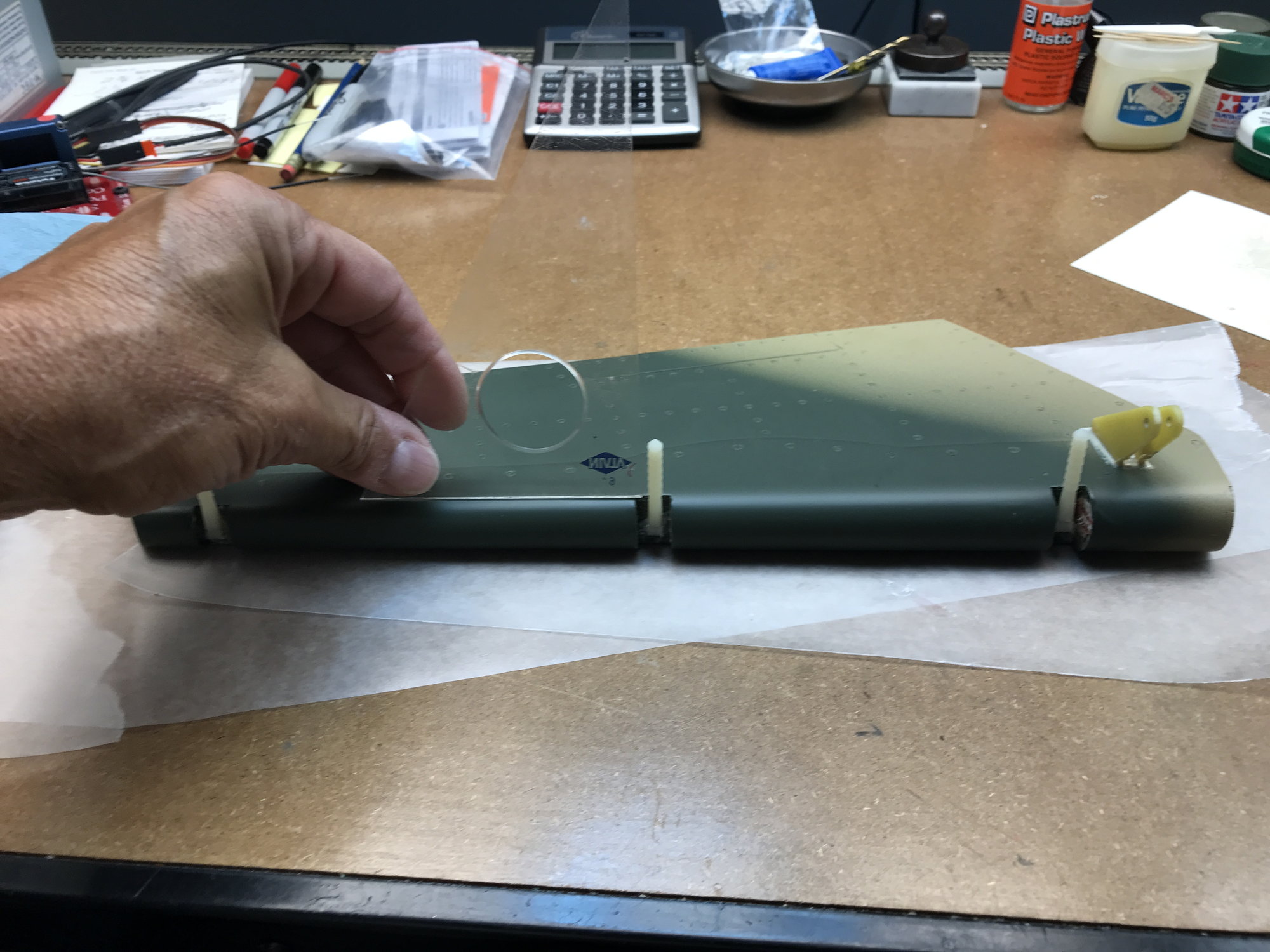
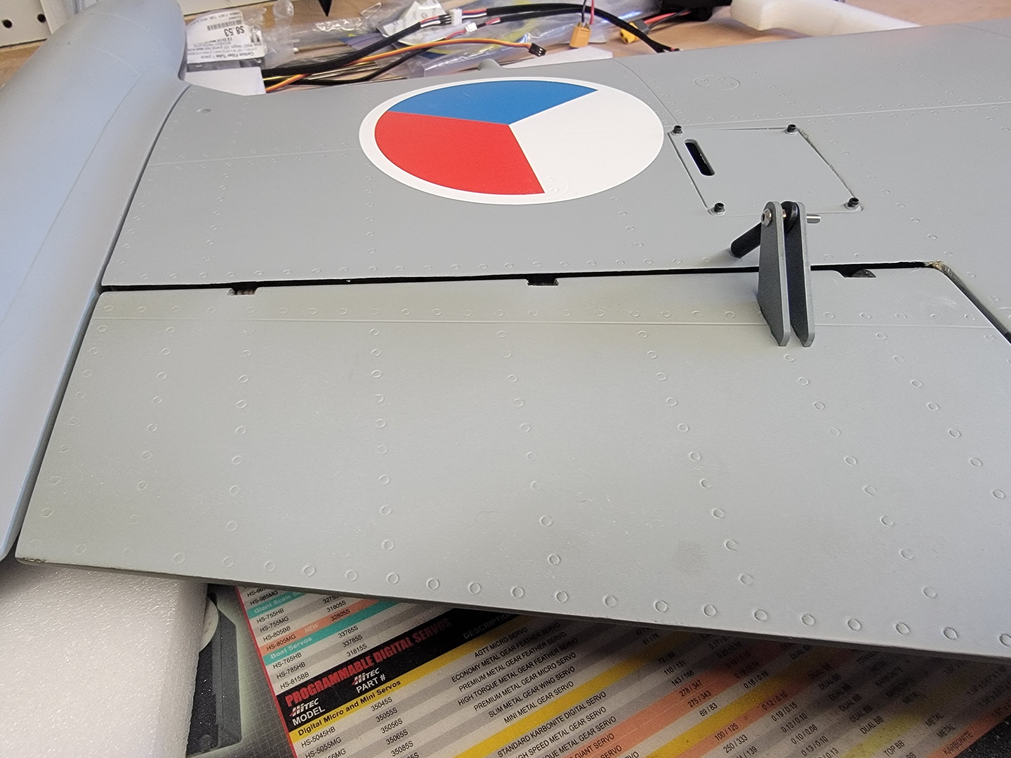
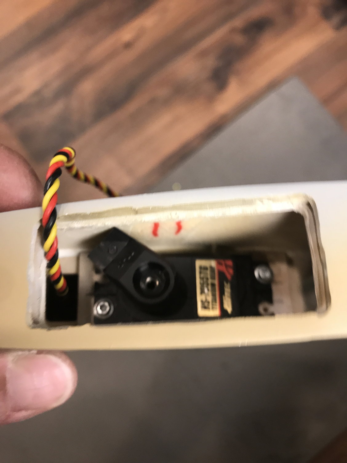
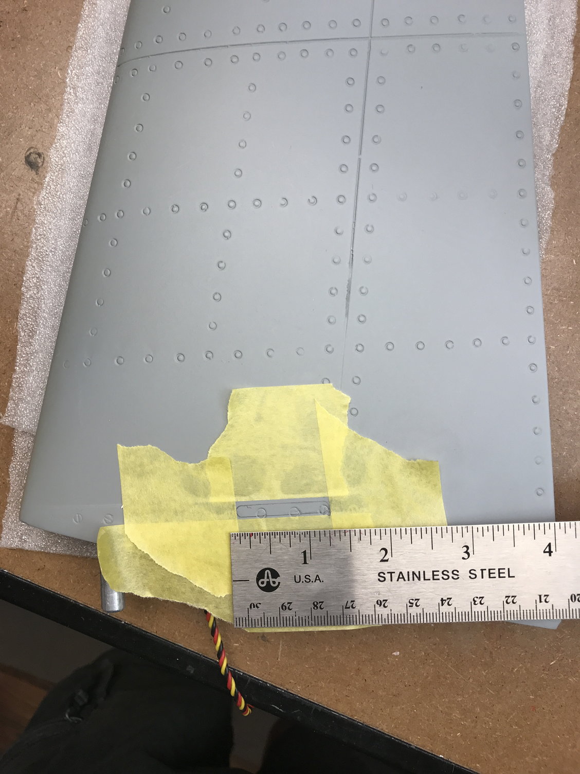
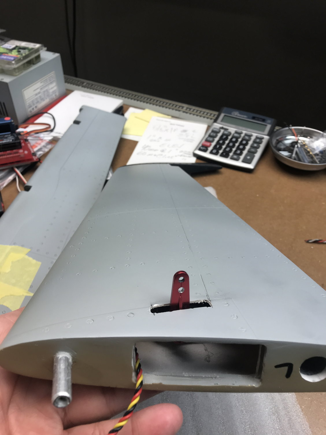
Next, I decided to tackle the elevator stab assembly. Once again, you will need to shorten the control horns so they will attain the correct depth in the control surface. The servo is mounted in the root of the stab with the spindle forward. You will also need to cut the servo arm opening in the bottom of the stab. There are many ways of doing so and I chose to mount a partial nylon horn on the servo temporarily and mark the inside of the stab where it touches. I then measured the distance from the root to the mark and transferred that measurement to the outside bottom of the stab. From there I used a Dremel with a cut-off wheel to make the slot for the servo arm (see pics below).
More later ......
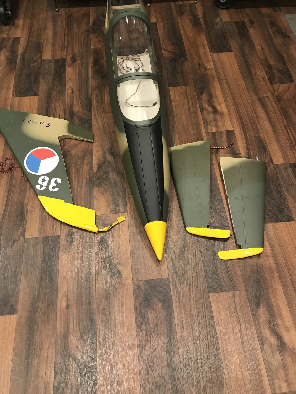
That said, I have been busy doing some extraneous things. I decide to differentiate my L-39 from the others by painting the top of the fin, stab ends and nose Hi Vis Yellow. I located a pic of a camo (like mine) scale L-39 with this paint scheme. (Pics show the gloss Yellow that needs to have a flat coat painted soon)
Next, I decided to tackle the elevator stab assembly. Once again, you will need to shorten the control horns so they will attain the correct depth in the control surface. The servo is mounted in the root of the stab with the spindle forward. You will also need to cut the servo arm opening in the bottom of the stab. There are many ways of doing so and I chose to mount a partial nylon horn on the servo temporarily and mark the inside of the stab where it touches. I then measured the distance from the root to the mark and transferred that measurement to the outside bottom of the stab. From there I used a Dremel with a cut-off wheel to make the slot for the servo arm (see pics below).
More later ......