Yellow F-15 ARF Assembly Thread
#279

My Feedback: (76)
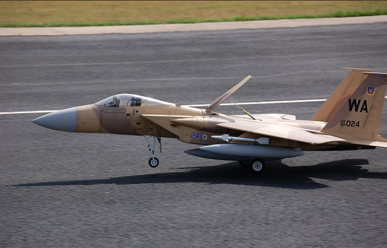
Anyone have pictures of light kit installation in the tail? I am almost done painting mine too, this was a kit build plane, is there more than one screw to remove the fins? I don't know if the original builder glued the vertical fins in. On another note, I have seen Brian's F-15 at best in the West and he flies it awesome. He's came with a CNC made mid brace instead of the typical wood one, not much heavier, but certainly a lot stronger.
Thanks
Ralph
Thanks
Ralph
#280

Could anyone give me any tips or point me in the right direction of how to install the custom cockpit into the airframe? (as pictured on my post on pg. 11 at the bottom) I have trimmed the outside edge quite a bit now and just cant figure out if/which parts of the cockpit mount to the fuselage or canopy ledge either above or below the ledge... do i need to separate the front dash/hud section from the cockpit to remain in the fuse when the canopy is removed?
Thanks
Thanks
#282

My Feedback: (14)
Br,
I used Dan Gill's (details4scale.com) F-16 centerline wet tank. It worked fine, but you will need to use large diameter tubing on the plumbing so you don't get too much pressure drop .. more of a problem when fueling than when flying...
Dave
(Yes, I know, F-16 tank not quite right for an F-15..)
I used Dan Gill's (details4scale.com) F-16 centerline wet tank. It worked fine, but you will need to use large diameter tubing on the plumbing so you don't get too much pressure drop .. more of a problem when fueling than when flying...
Dave
(Yes, I know, F-16 tank not quite right for an F-15..)
#283

My Feedback: (38)
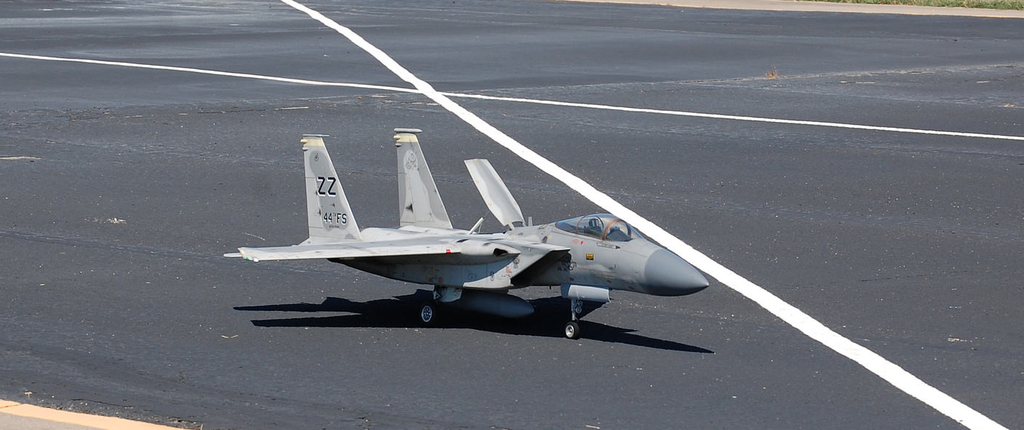
Mine is the gray one in the pics I posted above, I have at least 50 flights on it, the center tank works perfect, and looks great. I used this one, 50oz, complete for under 200$
http://www.details4scale.com/
Look in the fuel tank selection
http://www.details4scale.com/
Look in the fuel tank selection
#286
Senior Member
My Feedback: (1)
Join Date: Oct 2002
Location: Bossier City, LA,
Posts: 543
Likes: 0
Received 0 Likes
on
0 Posts
Hello
I have an extra nose strut, I will hold on to the gear, or sell as a set with the whole kit.
I have extra stabs and fins, hatches, main canopy,doors, main former and a canopy frame.
Thanks
Kevin
I have an extra nose strut, I will hold on to the gear, or sell as a set with the whole kit.
I have extra stabs and fins, hatches, main canopy,doors, main former and a canopy frame.
Thanks
Kevin
#290

Hey does anyone happen to know the exact dimensions of the set screws and all of the bolts that hold the attachment rods for the vertical and horizontal stabilizers? I'm afraid I May have stripped out the set screws for the horizontal stabilizer that hold the attachment rods in to the fuselage. I was using a standard type Hex wrench (5/32 or whatever it was) and think that maybe they were supposed to be 2 mm metric. Also the bolts or whatever screws hold the vertical stabilizers in and the attachment to the fuselage on those then on the fin rods that rotate. The set screws have pointed ends. I do not know the best place to purchase new ones or how to determine the sizes. This is about the only thing keeping me from finishing this model. I just basically need to buy all new screws for all of the attachments for all of the rear stabilizers. Thanks
Last edited by bRandom; 09-24-2016 at 07:15 AM.
#291

My Feedback: (3)
Join Date: Jun 2010
Location: Aldie, VA
Posts: 63
Likes: 0
Received 0 Likes
on
0 Posts
Hey does anyone happen to know the exact dimensions of the set screws and all of the bolts that hold the attachment rods for the vertical and horizontal stabilizers? I'm afraid I May have stripped out the set screws for the horizontal stabilizer that hold the attachment rods in to the fuselage. I was using a standard type Hex wrench (5/32 or whatever it was) and think that maybe they were supposed to be 2 mm metric. Also the bolts or whatever screws hold the vertical stabilizers in and the attachment to the fuselage on those then on the fin rods that rotate. The set screws have pointed ends. I do not know the best place to purchase new ones or how to determine the sizes. This is about the only thing keeping me from finishing this model. I just basically need to buy all new screws for all of the attachments for all of the rear stabilizers. Thanks
For the horizontal stab, I used these:
McMaster Carr - 91210A113
[TABLE="class: SpecTbl"]
[TR="class: AttrDivider NormalAttrRow SpecTblRow"]
[TD="class: SpecTblAttrCell"]Point Style[/TD]
[TD="class: SpecTblValCell"]Cone[/TD]
[/TR]
[TR="class: AttrDivider NormalAttrRow SpecTblRow"]
[TD="class: SpecTblAttrCell"]Material[/TD]
[TD="class: SpecTblValCell"]Alloy Steel[/TD]
[/TR]
[TR="class: AttrDivider NormalAttrRow SpecTblRow"]
[TD="class: SpecTblAttrCell"]Thread Size[/TD]
[TD="class: SpecTblValCell"]M4[/TD]
[/TR]
[TR="class: AttrDivider NormalAttrRow SpecTblRow"]
[TD="class: SpecTblAttrCell"]Pitch[/TD]
[TD="class: SpecTblValCell"]0.7 mm[/TD]
[/TR]
[TR="class: AttrDivider NormalAttrRow SpecTblRow"]
[TD="class: SpecTblAttrCell"]Length[/TD]
[TD="class: SpecTblValCell"]8 mm[/TD]
[/TR]
[TR="class: AttrDivider NormalAttrRow SpecTblRow"]
[TD="class: SpecTblAttrCell"]Drive Style[/TD]
[TD="class: SpecTblValCell"]Hex Socket[/TD]
[/TR]
[TR="class: AttrDivider NormalAttrRow SpecTblRow TblEnd"]
[TD="class: AttrWithBottomPadding SpecTblAttrCell"]Hex Size[/TD]
[TD="class: AttrWithBottomPadding SpecTblValCell"]2 mm
[/TD]
[/TR]
[/TABLE]
For the vertical stab: I drilled and tapped for 6-32 socket head cap screw. Note that you have to be careful, the first surface is drilled for a slip fit of the screw; then you tap the second surface for 6-32 thread. That way the screw head seats against the first surface and the threads allow the second surface to grip the carbon rod that serves as the spar for vertical stab.
Last edited by MachLoop; 09-24-2016 at 10:53 AM.
#293

Ok well the left hor stab set screw was totally stripped and threadlocked, so I tried to drill it out after failing with a stripped screw remover device, and of course there seemed to be no way to keep the drill bit perfectly centered so the hole was too big for the M4... so I tapped it out with M5 and it seems like it will be ok. Placed my order with McMasters for the pointed alloy set screws, and i guess as long as the point fits into the pre-drilled pointed hole in the actual elevator insert rod, it will center up and I can lock it down with the socket cap screw that holds around the elevator rod
Last edited by bRandom; 09-28-2016 at 12:42 PM.
#294

Well I could really use some advice now. I have spent many many hrs. getting the tail surfaces installed and connected to the servos only to be back to square one. I am finding the tail surfaces extremely difficult to get right. I ordered the set screws with the points and had to attach the left rudder with the Robert hinge points. This model was a kit and not an arf but a pro builder built it up to arf status.
1. I hysoled the hinges into the rudder surface and after they dried I installed the surface hinges into the rear of the vert. Stab. However the hinge holes were at about a 15 degree angle downward from the rudder surface in the vert stab and I had the holes full of wet hysoled so I forced them to bend downward to go in the holes anyway hoping they would still travel with little resistance. (Terrible idea... Shoulda waited for the holes to dry and red rill)
2. Got everything hooked up and the arms for the rudder servos bind against the elevator servo arms (they actually barely clear the right side but interfere quite a bit on the left side.
3. I did not like the heavy duty nylon servo arms they used and they were flexing because of the very difficult to move rudder surfaces I poorly glued into the hinges (lots of resistance because I suck at installing them) so I spent hours getting some nice aluminum arms attached to the elevator servos JR8411's and wanted to attach aluminum arms to the rudder servos (ds3421's) also.
4. The back side of the aluminum servo arms have a socket head screw and nut on the other side and extend further out. This made the router connector arm find even more against the back of the elevator servo arm. I also switched the rudder servos to aluminum arms and thought if I used a ball link they would clear to the side of the elevator servo arms rather than being right on top of them. Let's just say this didn't clear either because the aluminum arms sit closer to the top of the servo so I just moved arm closer to the servo top and back to the old position of the nylon arm placement. Then I tried putting the nylon rotor servo arm back on with the ball link but it flexed the arm.
5. I finally went back to the original rudder servo arm heavy duty nylon and I have to do something drastically different. The rudders are so difficult to move on both sides that the servos can barely even budge them if any so I have sent Scott one of the writers back off of the airplane and need to drill the hinges out and redo them.
I love this airplane but the tail surfaces are a complete nightmare. Does anyone have any clue of what I should do? All I could think of is either putting more ply underneath the rudder servo so it sits higher than the elevator servo and clears the arm. The servos cannot move much up or down to space them out more I am at a loss here I have spent easily 15 hours to 25 hours on the surfaces and now I have to redo everything.
Also I really really am having a hard time installing rubber inches without getting blue and the hinges and screwing them up totally I have looked for videos on good installation techniques but nothing.
Here are some pictures that me so what's going on but if anyone has pictures of theirs and I would be interested in seeing them or any advice would be great I can't waste anymore time on this with a baby in the house and very limited time to sneak away and work on my jets.
Thanks!
#296

My Feedback: (24)
As far as hinges, they need to be 90 to surface hinge line, as shown in picture. To remove hinges, you can use a piece of brass tube that will slip over the hinges you used. Sharpen one end, and I've used a drumel to cut teeth into the end end of the tube. Put it in a drill, and slowly drill out old hinges. Can also just cut them flush, and put new hinges in a different location
Good luck
#297

My Feedback: (24)
As far as hinges, they need to be 90 degrees to surface hinge line, as shown in picture. To remove hinges, you can use a piece of brass tube that will slip over the hinges you used. Sharpen one end, and I've used a drumel to cut teeth into the end of the tube. Put it in a drill, and slowly drill out old hinges. Can also just cut them flush, and put new hinges in a different location
Good luck
Last edited by 70 ragtop; 10-03-2016 at 07:36 PM.
#299

Thanks ragtop this will help. I think the servos are already as far up and down in the slots as they can go but I will try removing them and see if I can slide them a little further. It seems like the rod that goes into the rudder surface to move it is pretty hard to move even with no rudder attached. Maybe I can oil them or something. Or I wonder if I got thread lock into the copper tube? Looking at step 228 it looks like they ground the top of the rudder servo horn down so it clears the cover as it is probably moved up slightly higher than mine. Thanks for the assistance!
Last edited by bRandom; 10-04-2016 at 02:36 PM.
#300

Could anyone explain to me how or what page in the manual, the instructions are on, for bolting the wings into the fuselage so they cant slide out during flight. I cannot seem to find it. Thanks
Last edited by bRandom; 10-21-2016 at 03:06 AM.


