


1/7th F-14D Scratch build thread *building started*
 09-26-2013, 09:39 AM
#1201

SQUIRREL!!!!!!!....DID YOU SAY A-10
http://www.ohmagif.com/wp-content/uploads/2012/02/dog-giving-a-surprised-look.gif
Last edited by yeahbaby; 09-26-2013 at 09:43 AM.
 09-26-2013, 01:36 PM
#1202

Not much so far today..
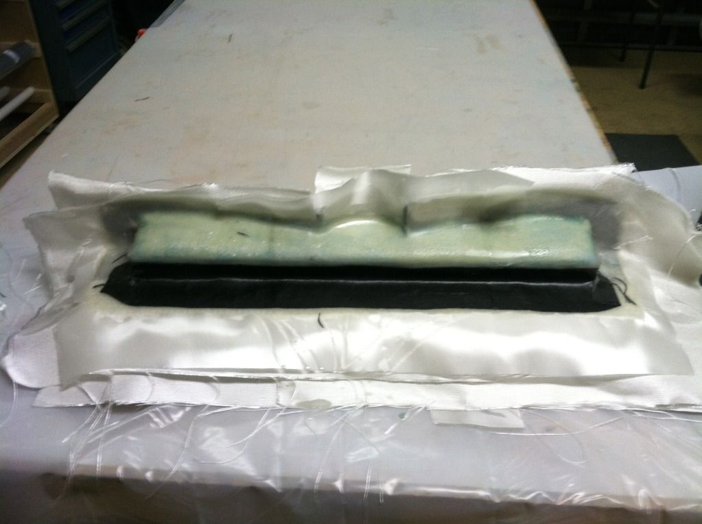
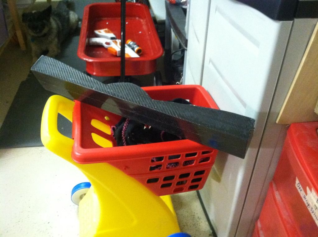
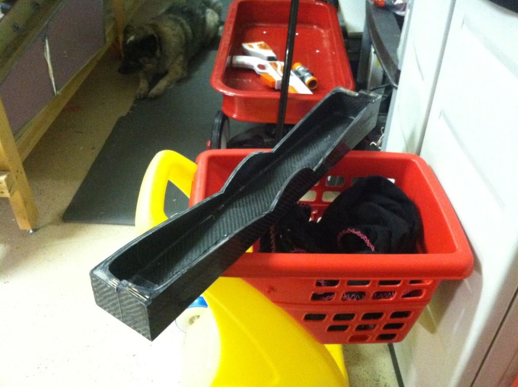
Finished the majority of the construction on the box spar plug and glassed it. The rest of it will be where a parting plane will be, which will get glued on later.
then I made up a Glass/airex/glass panel for some of the internals of the fuselage:
Finished the majority of the construction on the box spar plug and glassed it. The rest of it will be where a parting plane will be, which will get glued on later.

then I made up a Glass/airex/glass panel for some of the internals of the fuselage:


 09-27-2013, 11:49 AM
#1205

My Feedback: (12)

Join Date: Aug 2002
Location: Scottsdale, AZ
Posts: 4,462
Likes: 0
Received 0 Likes
on
0 Posts
Awesome Thomas!!! That tire mold is massive!! I don't even dare ask what all that machine work set you back :-( Lovin it man!! For your glass panel, in the future if you want to forego the board and can flattening system you could always lay it up between 2 peices of tempered glass, that thick kind. Or do the layup then bag it and put it between 2 pieces of glass, should keep it nice and flat. Look good bro!! Making me want to work on the Intruder more.
09-27-2013, 01:05 PM
#1206
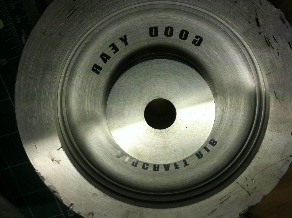
Ian, you'd be surprised on the price.. 
The tire is 5 1/4" and the chunk of aluminum is 7" x 2" each.
I would of done the layup between glass panels, but i didn't have any and didn't want to have to go source it. these panels are completely critical to being absolutely flat anyways. plus i don't do layups of flat panels very often either.
09-27-2013, 07:50 PM
#1207
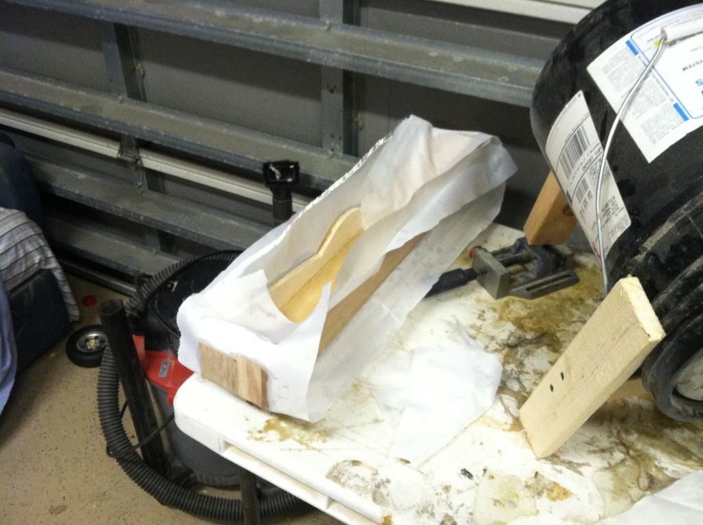
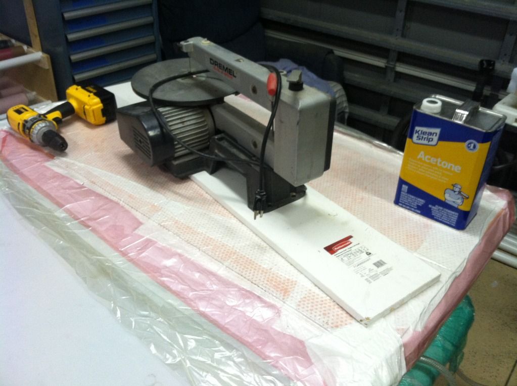
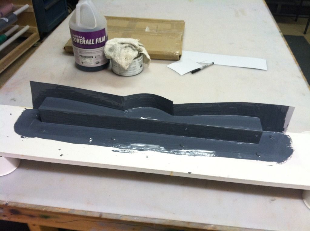
After trimming the glass, putting a coat of primer on, and then filling some pinholes on the box spar plug, i covered it in aluminum duct tape. I'm not concerned about the ridges left from the overlaps on the surface of this part as they are so small you'll probably never notice them. I'm just ready to get this part done and molded, no since dragging it out by doing 20 rounds of paint and sand to make it 100% perfect when its going on the inside of the jet.
Then I made up a parting plane from a piece of melamine shelving board and some .020" plastic. The spar plug is now ready to be molded! I'll start doing this on sunday, because tomorrow i'm going over to my buddies to cut some test internals out on his CNC router. Once I know the internals fit like I want them to, i'll be ordering the actual materials to cut them from.

Then I made up a parting plane from a piece of melamine shelving board and some .020" plastic. The spar plug is now ready to be molded! I'll start doing this on sunday, because tomorrow i'm going over to my buddies to cut some test internals out on his CNC router. Once I know the internals fit like I want them to, i'll be ordering the actual materials to cut them from.
 09-28-2013, 04:07 PM
#1208
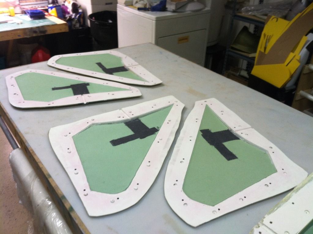
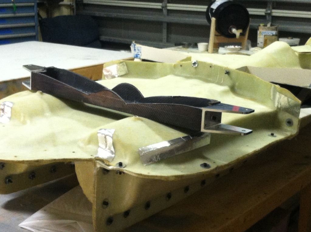
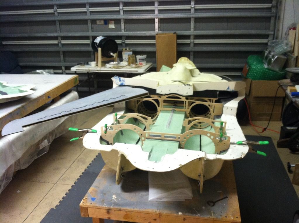
Went to my buddy chris' place early this afternoon to cut out some test pieces for the internal structure of the F14:
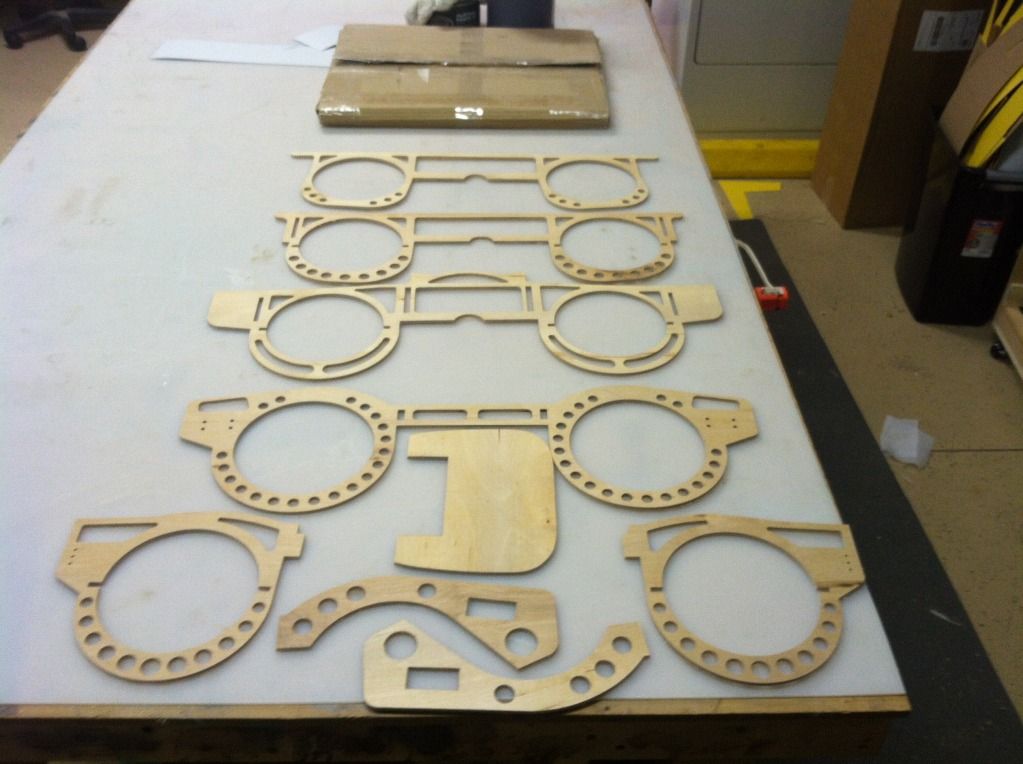
Then popped the tops off the fuselage mold to check their fit. Of all the parts, only one fit nearly perfect. All the rest required some adjustment. So all those have been readjusted in CAD and we will cut some new updated ones out tomorrow to check to be sure the adjustments are correct.
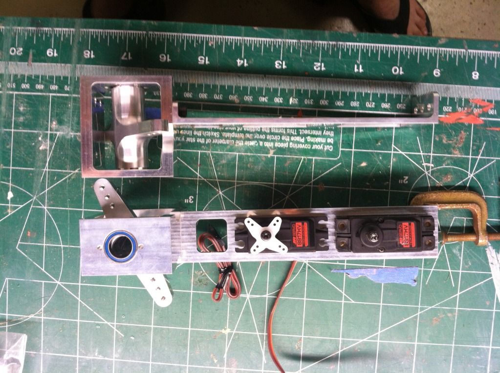
Here is a shot of the prototypes stab mechanism in place with its support bulkheads:
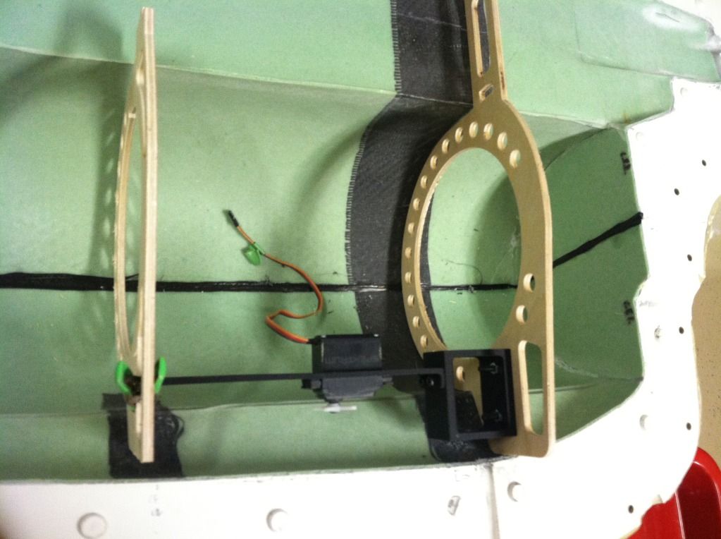
The stab mechanism is reversable, so it can either be mounted like it is now, or rotated 180* so the servo output shafts face towards the center of the airframe.
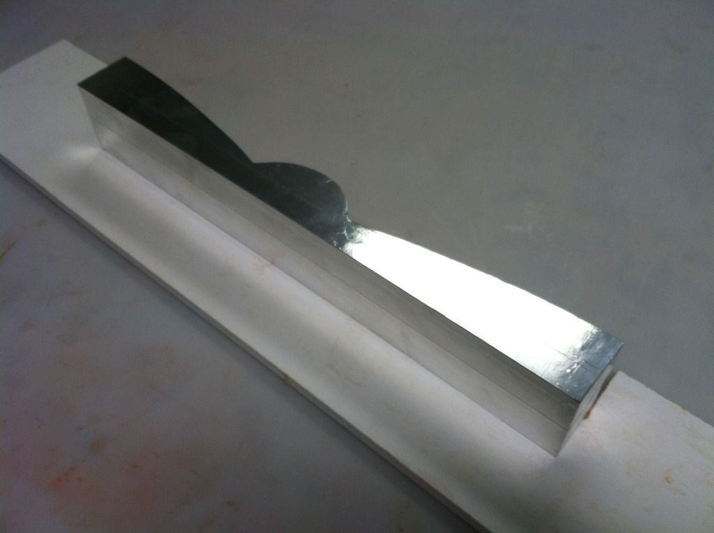
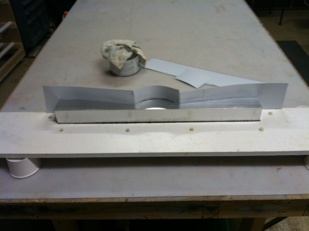
The box spar mold was also started:
Then popped the tops off the fuselage mold to check their fit. Of all the parts, only one fit nearly perfect. All the rest required some adjustment. So all those have been readjusted in CAD and we will cut some new updated ones out tomorrow to check to be sure the adjustments are correct.
Here is a shot of the prototypes stab mechanism in place with its support bulkheads:
The stab mechanism is reversable, so it can either be mounted like it is now, or rotated 180* so the servo output shafts face towards the center of the airframe.
The box spar mold was also started:
 09-29-2013, 04:33 PM
#1210

My Feedback: (6)
Join Date: Oct 2002
Location: St. Catharines,
ON, CANADA
Posts: 193
Likes: 0
Received 1 Like
on
1 Post
I gotta say Thomas....4 years ago when you started this thread I thought PFFTTT!!!, not gonna happen. Boy was I wrong.....I admire your dedication and effort on such a massive project.
 10-05-2013, 07:37 PM
#1213
Finally back home after a long week in Louisiana, and lots of goodies were waiting for me
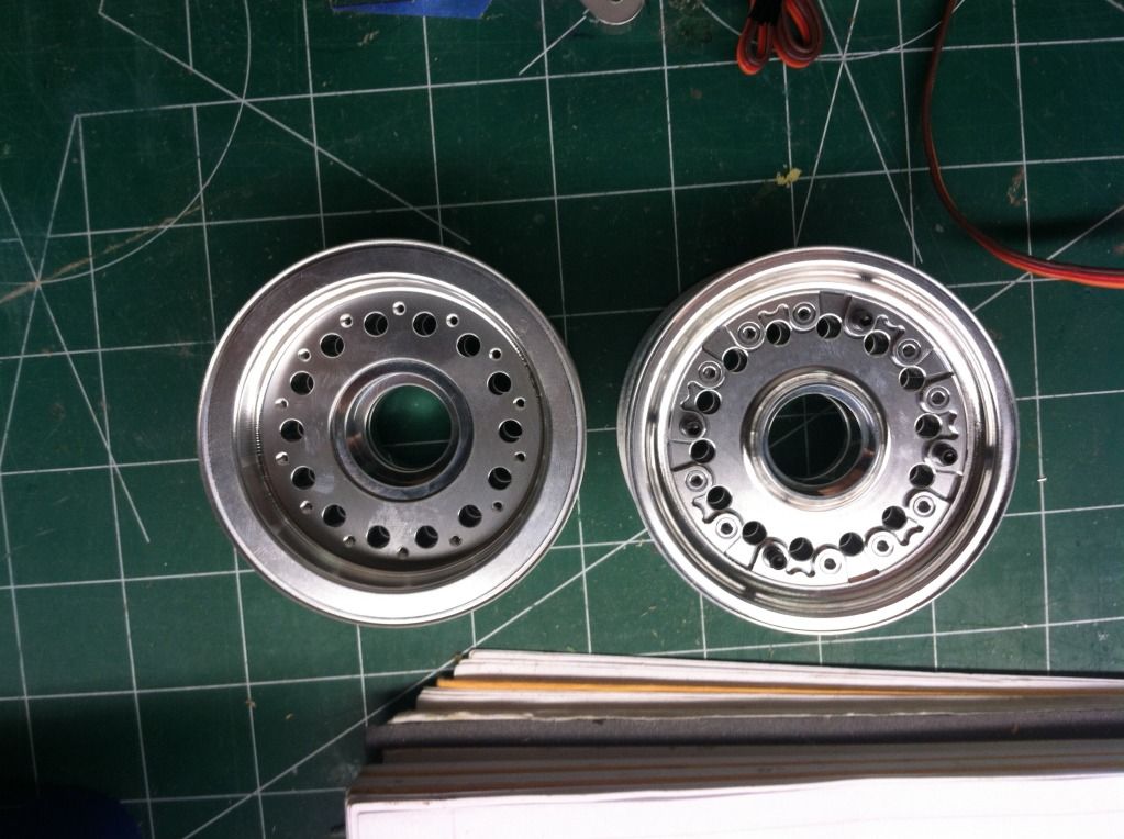
First up.. Main rims were here. I messed up on the alignment flange dimensions on the face rim half so its a press fit. I'll have to chuck this up in the lathe so its a slip fit and adjust the Cad Files..
Detail shot of the tire mold. The center alignment pin had welded itself to the other half due to the two halves being twisted and galling each other.. it was very fun getting the halves apart.. again, my fault as i didn't undersize the alignment pin enough (its only about .003" to large).
Wing pivot brackets, Pivot axle's, and wing pivot bearings:
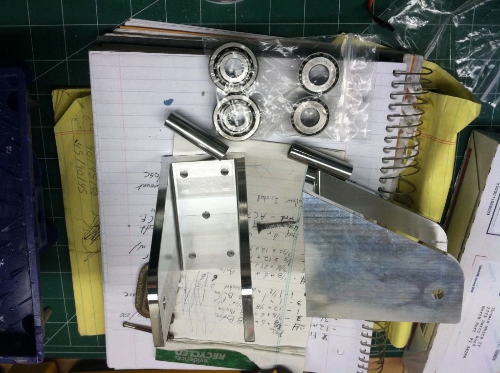
The Stab mechanism assembled. Its designed to hold two DS8711's or equivalent. The stab pivot shaft is supported on twin ABEC-7 twin Shielded ball bearings. You can see the Control arm allows for 1", 1 1/4" and 1 1/2" on center (per half) ball link attachments. The arm is also already tapped for 4-40 ball link attachment bolts, but also possible to be 6-32 or 8-32. I am currently working on a design for solid aluminum servo mount grommets to replace the rubber and brass grommets included with the servo's.
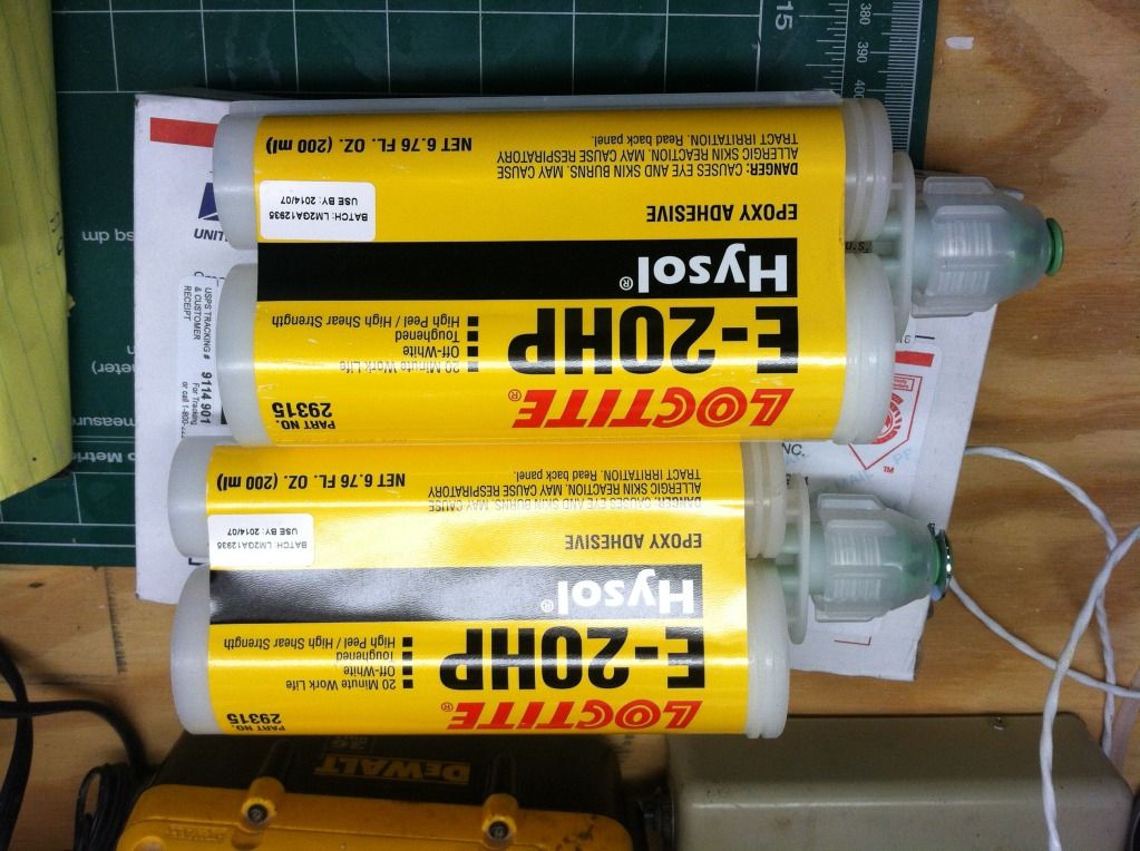
And then two Really big (200ml) tubes of Hysol for fuselage internals install and assembly
First up.. Main rims were here. I messed up on the alignment flange dimensions on the face rim half so its a press fit. I'll have to chuck this up in the lathe so its a slip fit and adjust the Cad Files..

Detail shot of the tire mold. The center alignment pin had welded itself to the other half due to the two halves being twisted and galling each other.. it was very fun getting the halves apart.. again, my fault as i didn't undersize the alignment pin enough (its only about .003" to large).

Wing pivot brackets, Pivot axle's, and wing pivot bearings:

The Stab mechanism assembled. Its designed to hold two DS8711's or equivalent. The stab pivot shaft is supported on twin ABEC-7 twin Shielded ball bearings. You can see the Control arm allows for 1", 1 1/4" and 1 1/2" on center (per half) ball link attachments. The arm is also already tapped for 4-40 ball link attachment bolts, but also possible to be 6-32 or 8-32. I am currently working on a design for solid aluminum servo mount grommets to replace the rubber and brass grommets included with the servo's.

And then two Really big (200ml) tubes of Hysol for fuselage internals install and assembly
 10-11-2013, 05:19 PM
#1214
Progress:
New horizontal stabs layed up. I wasnt happy with the weight of the last ones, or how badly they were joined:
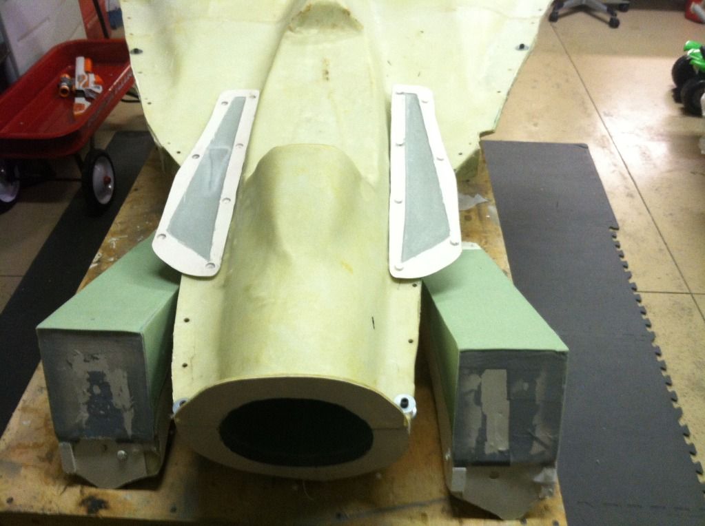
I also layed up a new set of inlet ramps and the second ventral fin:
Then the carbon box spar was removed from the mold and trimmed:
Then the pivot brackets were installed:
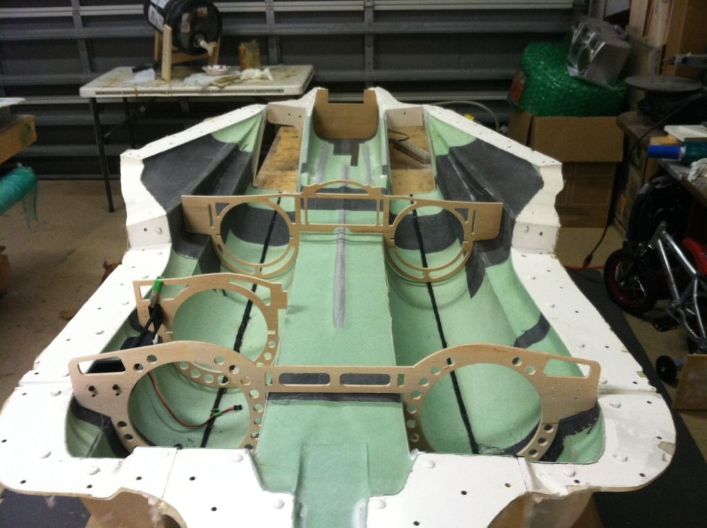
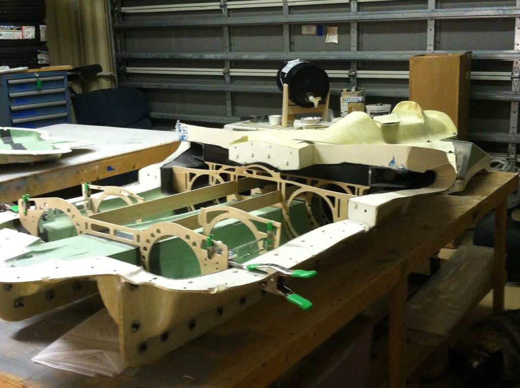
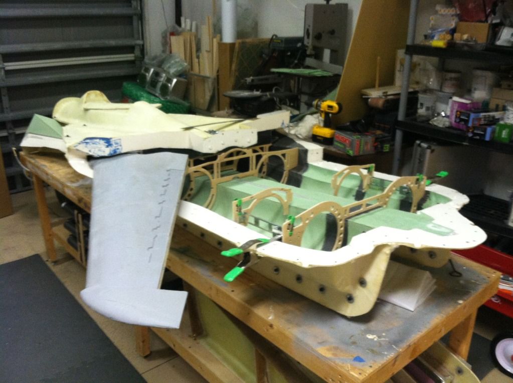
Then i started prepping the internal structure again to test the machined components fit. The two narrow pieces of balsa on the vertical will be two longerons full depth of the fuselage from the stab pivot bulkhead to the carbon box spar support bulkheads:
Then i was bored and decided to see how the wing fit:
New horizontal stabs layed up. I wasnt happy with the weight of the last ones, or how badly they were joined:
I also layed up a new set of inlet ramps and the second ventral fin:
Then the carbon box spar was removed from the mold and trimmed:
Then the pivot brackets were installed:
Then i started prepping the internal structure again to test the machined components fit. The two narrow pieces of balsa on the vertical will be two longerons full depth of the fuselage from the stab pivot bulkhead to the carbon box spar support bulkheads:
Then i was bored and decided to see how the wing fit:

 10-12-2013, 09:23 AM
#1217
LOL jeremy. The landing gear is the hold up right now. If i could get two or three people on board for one of these things and able to pay for the gear for their models, things would progress a wee bit quicker (and i would cut them a hell of a deal on the F14!). Right now im almost at a stand still, till some more materials come in from germany and i get some gear.
 10-12-2013, 01:31 PM
#1221
Wow, what a project!
I don't understand much about composites but can you please explain the box spar?
To me (the layman) it looks all wrong with two weak points near the centre where I
would imagine most of the stress would be. Am I missing something? - John.
I don't understand much about composites but can you please explain the box spar?
To me (the layman) it looks all wrong with two weak points near the centre where I
would imagine most of the stress would be. Am I missing something? - John.
10-12-2013, 01:45 PM
#1222
The box alone without the fuselage top will support 800lbs of force Per bracket attachment point before failure. The thing is extremely overbuilt. It will all come together when i get further invloved in its attachment.
10-12-2013, 06:24 PM
#1223
Member
Join Date: Feb 2002
Location: NorthEast,
NJ
Posts: 76
Likes: 0
Received 0 Likes
on
0 Posts
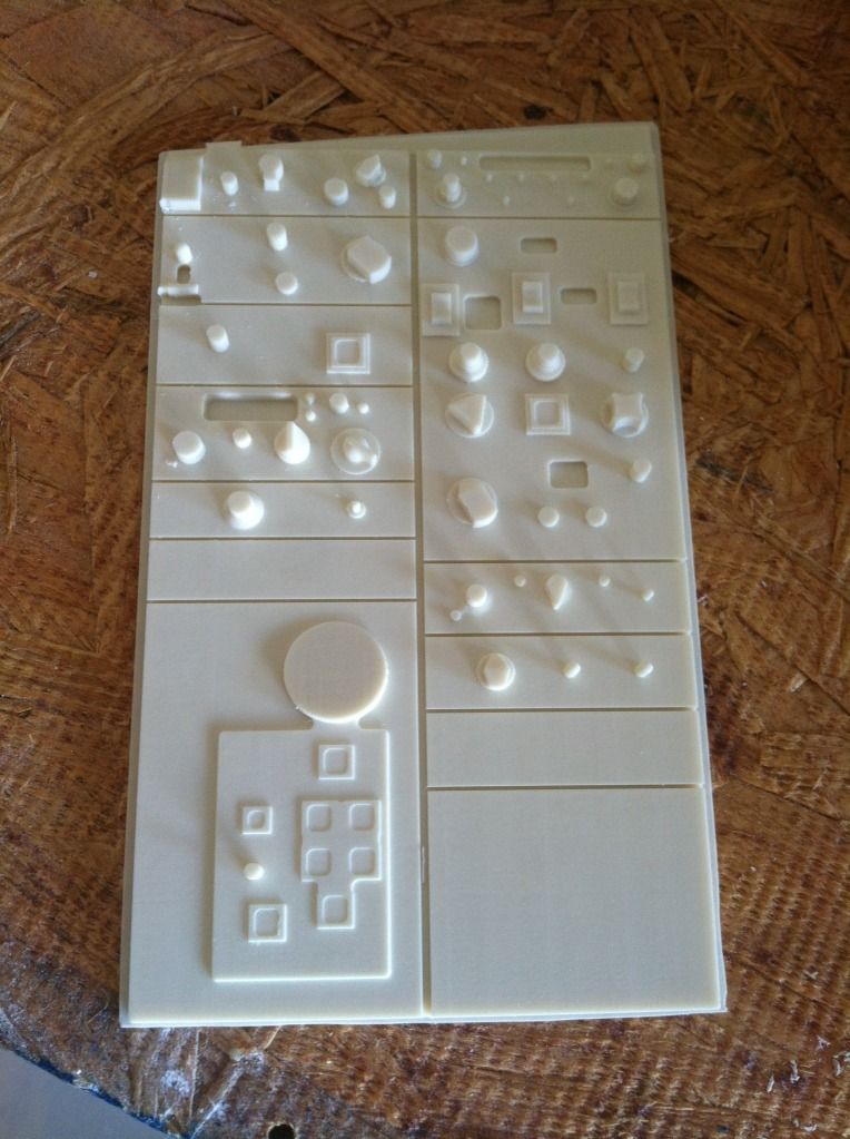
Amazing work Thomas. Sorry I haven't been able to help out with some of the cockpit details, I don't think my machine would produce nearly the quality of what you have there. If there are any other general parts you could use a prototype of please let me know. Can't wait to see her fly. Great work, right up there with Lance's SR-71.
Eric
Eric
10-13-2013, 01:43 PM
#1224


Last edited by Flakbait; 10-13-2013 at 01:44 PM. Reason: spelling