


Ziroli 1/6 Hellcat Build
 11-30-2019, 07:46 PM
#226

Thread Starter
Slow build. Yes, I know. The last six months have been interesting: "Opportunity" to look for new work, surgery and father passed away. He served in Japan at the end of WWII and earned his jump wings there with the 11th Airborne. He became a private pilot after the war and got me started in RC when I was old enough.
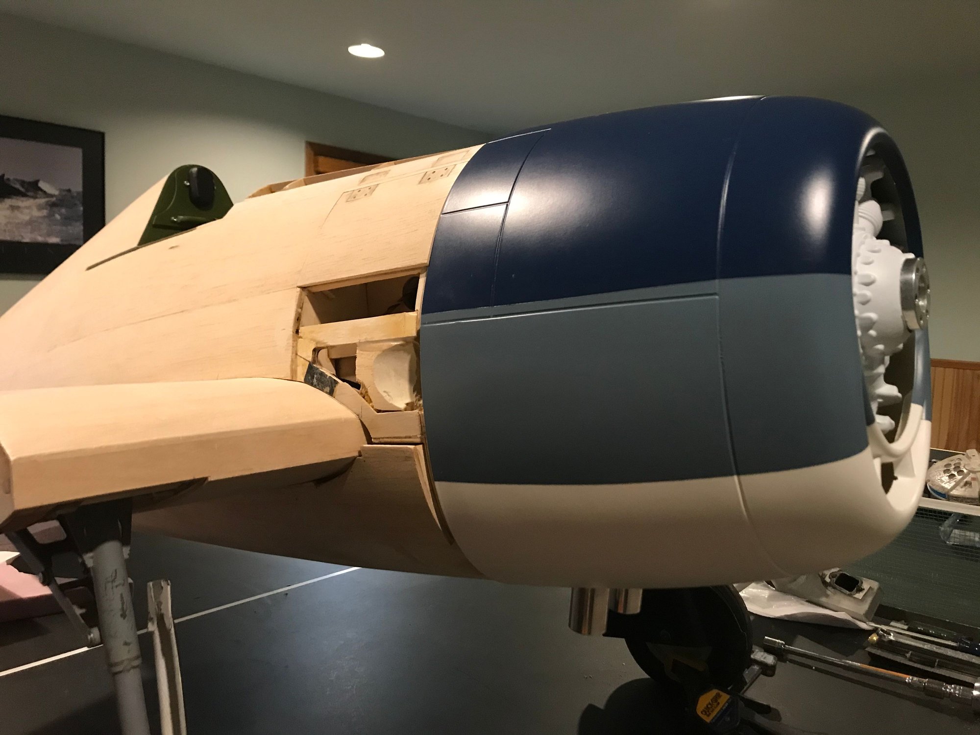
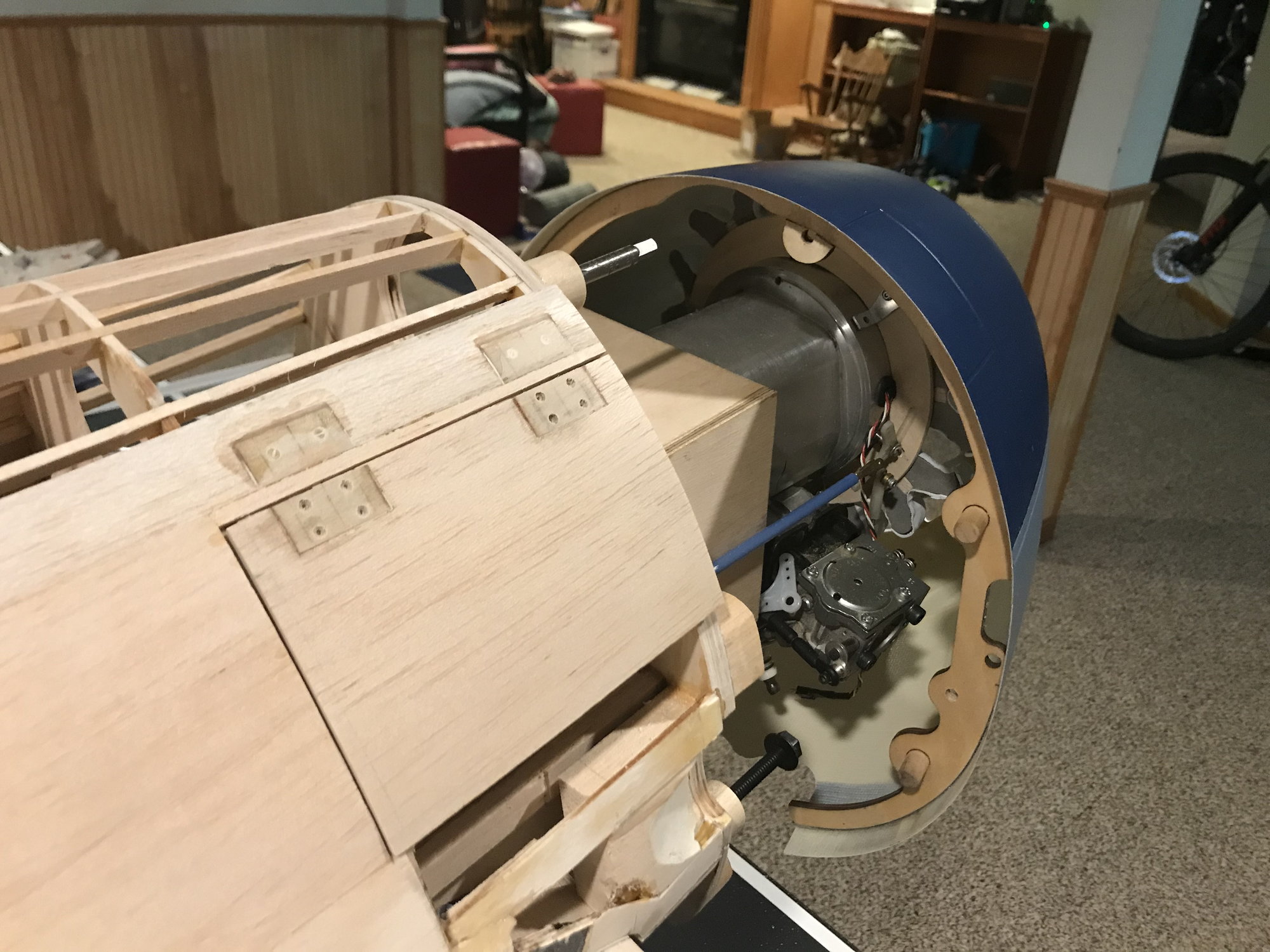
Making some progress fitting the Top-Flite cowling. To finish this portion of the job, I first needed to mount the dummy engine in order to see what site lines exist for the internal cowl mounting bolts.
1. Fill dummy engine backside with Cosplay Creative Clay Compound (C-4) and some balsa. I did this to provide some mounting surfaces and eliminate any vibration of the rather thin vacuum formed plastic. Also, provides some useful nose weight for balance.
2. Make and attach a plywood mounting ring to the back of the dummy engine.
3. Make mounting brackets out of aluminum L-bracket material.
4. Trim cowling chin area to provide clearance
Almost done with these steps - two more L-brackets to make. Will take engine off the plane to make and position these. Already, I can see where I can and cannot access the firewall with a long T-handled screw driver or hex bit. The 'out of the box' mounting bolt tabs on the Top-Flite cowling former won't work at at all, as the carburetor, exhaust and my mounting location for the air cylinder all block access. Next steps will be to finish the L-brackets for the dummy engine mount, install blind-nuts in the firewall for the cowling 1/4-20 nylon mounting bolts, and install mounting tabs to the already installed cowling former. The mounting bolts will pass through these tabs and into the blind nuts.
And then... strip back the already installed fuse sheeting in order to reshape the firewall to fit the cowling!
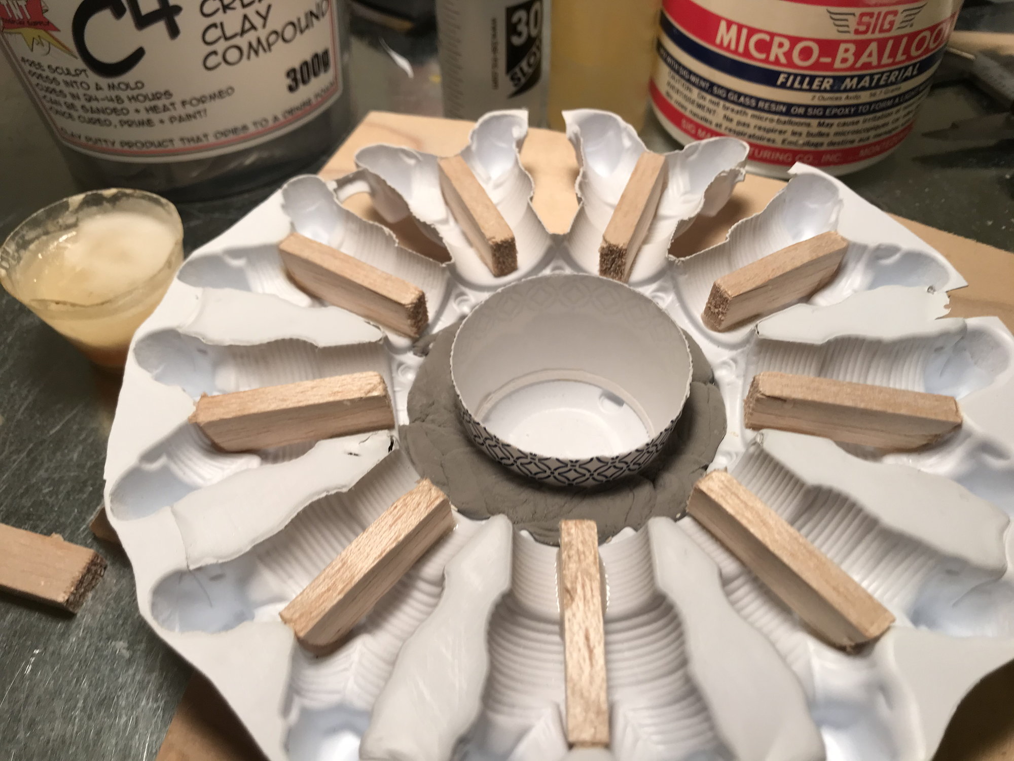
A paper cup in the center; balsa added for epoxy purposes; Cosplay Creative Clay Compound going in (this stuff is very light - it also shrinks a lot so overfill and let it set several days (a week) before sanding to shape; this is actually a foam, not traditional clay).
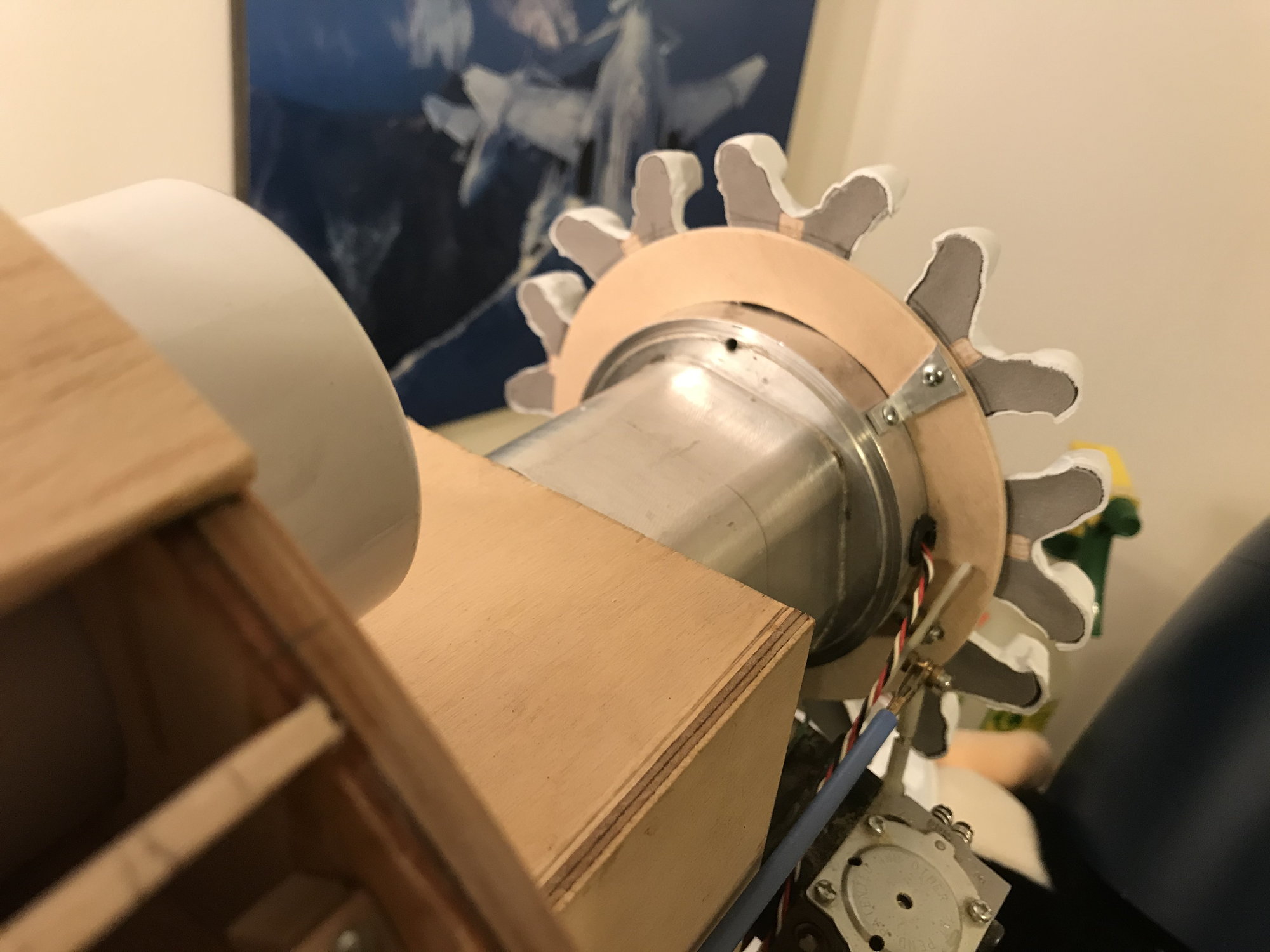
"Clay" filled and sanded with mounting ring attached. My aluminum brackets are a bit odd shaped - yes, I know. I'm having to reuse some pre-existing holes from a Byron dummy engine, where these old holes don't line up well with the new dummy engine's cylinders.
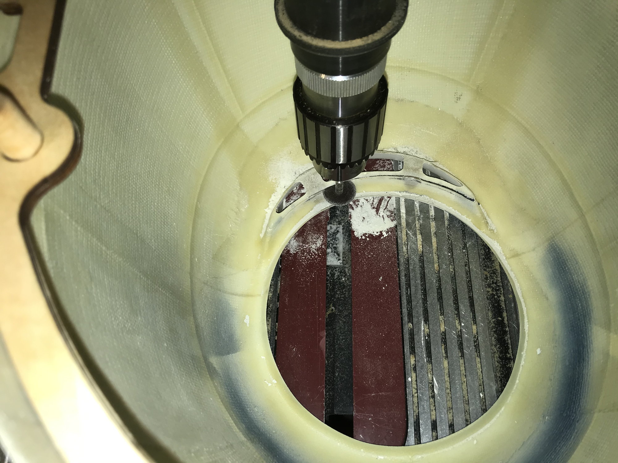
Removing material from the inside the 'chin' area of cowling; using my drill press and Dremel cutting wheel at a fixed depth. Used the same technique on Byron/Iron Bay cowlings, years ago.
With material removed from the backside of the 'chin,' I now have 5/32" clearance between the rocker covers of the dummy engine and the cowling.
That's all, for now.
Making some progress fitting the Top-Flite cowling. To finish this portion of the job, I first needed to mount the dummy engine in order to see what site lines exist for the internal cowl mounting bolts.
1. Fill dummy engine backside with Cosplay Creative Clay Compound (C-4) and some balsa. I did this to provide some mounting surfaces and eliminate any vibration of the rather thin vacuum formed plastic. Also, provides some useful nose weight for balance.
2. Make and attach a plywood mounting ring to the back of the dummy engine.
3. Make mounting brackets out of aluminum L-bracket material.
4. Trim cowling chin area to provide clearance
Almost done with these steps - two more L-brackets to make. Will take engine off the plane to make and position these. Already, I can see where I can and cannot access the firewall with a long T-handled screw driver or hex bit. The 'out of the box' mounting bolt tabs on the Top-Flite cowling former won't work at at all, as the carburetor, exhaust and my mounting location for the air cylinder all block access. Next steps will be to finish the L-brackets for the dummy engine mount, install blind-nuts in the firewall for the cowling 1/4-20 nylon mounting bolts, and install mounting tabs to the already installed cowling former. The mounting bolts will pass through these tabs and into the blind nuts.
And then... strip back the already installed fuse sheeting in order to reshape the firewall to fit the cowling!
A paper cup in the center; balsa added for epoxy purposes; Cosplay Creative Clay Compound going in (this stuff is very light - it also shrinks a lot so overfill and let it set several days (a week) before sanding to shape; this is actually a foam, not traditional clay).
"Clay" filled and sanded with mounting ring attached. My aluminum brackets are a bit odd shaped - yes, I know. I'm having to reuse some pre-existing holes from a Byron dummy engine, where these old holes don't line up well with the new dummy engine's cylinders.
Removing material from the inside the 'chin' area of cowling; using my drill press and Dremel cutting wheel at a fixed depth. Used the same technique on Byron/Iron Bay cowlings, years ago.
With material removed from the backside of the 'chin,' I now have 5/32" clearance between the rocker covers of the dummy engine and the cowling.
That's all, for now.
 12-01-2019, 07:18 AM
#227

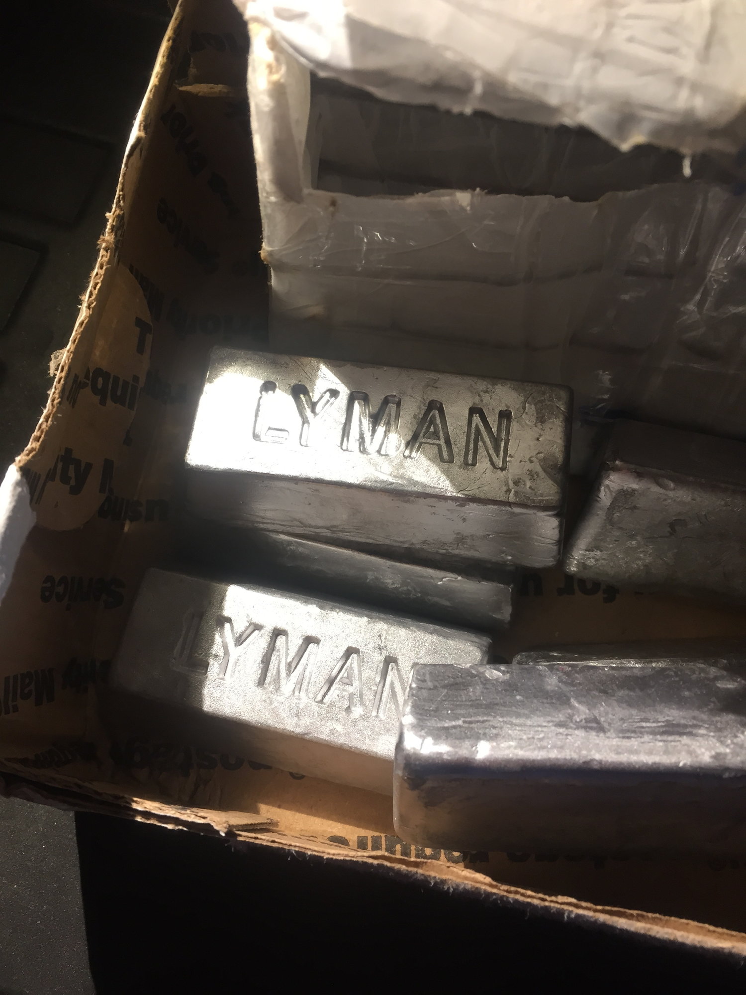
Looking awesome, something to consider when planning that engine box area is your going to need to add alot of weight....your going to need some room for it. I added around 5 pounds of lead bars to my engine box (with a DA100) and cowl so that took some thought and space to mount proper!
12-01-2019, 09:28 AM
#228
Thread Starter
Looking awesome, something to consider when planning that engine box area is your going to need to add alot of weight....your going to need some room for it. I added around 5 pounds of lead bars to my engine box (with a DA100) and cowl so that took some thought and space to mount proper!
I'll need to get creative, mock some dummy weights up and position them in various places in order to ensure access to the cowl mounting bolts.
This is 1/6 scale, same as the Byron. With a 69cc Precision Eagle engine, the Byron needed 2 lbs of lead up front. I'm pushing as much useful weight forward of the CG as possible. Just did a quick check with most components in place (missing: prop/spinner/pilot/muffler/ignition/spark plug/battery/receiver/wing tips), wheels down - it's quite nose heavy. Of course, there will be more fiberglass and paint work aft of the CG than in front, and wheels up, counterbalancing the current nose heavy condition.
Still, better to be nose heavy at this point of the build, than tail heavy.
Question: How do you mount your weights?
For the Byron, I built a box that made it easy to add or remove weight - I don't have the same space available, in this build.
12-01-2019, 10:03 AM
#229
Ha cool, I am actually working on a Byron Hellcat today! There are people on ebay that melt down lead into bars.....you might be able to find different sizes I think my were around 10 oz. they are nice and I just epoxied bars on my box as needed. I added as much weight to the chin of the cowl as I thought it could take without causing problems. I have also build a box like you to hold a pound or so as I adjusted things. during first flights.
LOL I may have some questions for you on that Byron, Im basically re-engineering the entire tail section at the moment!
I "rough" CG'd mine early in the process I calculated the cg spot with wings off and I was able to guesstimate as I finished it up
LOL I may have some questions for you on that Byron, Im basically re-engineering the entire tail section at the moment!
I "rough" CG'd mine early in the process I calculated the cg spot with wings off and I was able to guesstimate as I finished it up
Thanks for the advice! I haven't blocked out space for balance weight, and that could affect access to the cowl mounting bolts.
I'll need to get creative, mock some dummy weights up and position them in various places in order to ensure access to the cowl mounting bolts.
I did not realize its 1/6th lol but awesome thats a great size!
This is 1/6 scale, same as the Byron. With a 69cc Precision Eagle engine, the Byron needed 2 lbs of lead up front. I'm pushing as much useful weight forward of the CG as possible. Just did a quick check with most components in place (missing: prop/spinner/pilot/muffler/ignition/spark plug/battery/receiver/wing tips), wheels down - it's quite nose heavy. Of course, there will be more fiberglass and paint work aft of the CG than in front, and wheels up, counterbalancing the current nose heavy condition.
Still, better to be nose heavy at this point of the build, than tail heavy.
Question: How do you mount your weights?
For the Byron, I built a box that made it easy to add or remove weight - I don't have the same space available, in this build.
Last edited by show871; 12-01-2019 at 10:28 AM.
 04-17-2020, 08:30 PM
#231
Thread Starter
Sheltering in place from Covid-19, here in Michigan. So far, all family, friend, co-workers safe. Haven't been to office or plant in 4 weeks. Will be furloughed for a couple weeks. So, making some progress on the Hellcat.
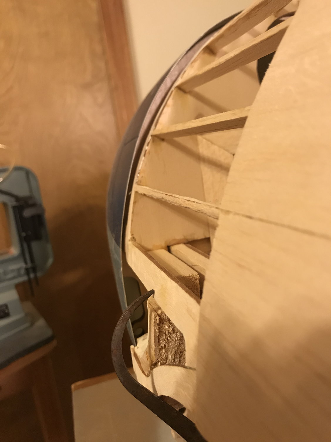
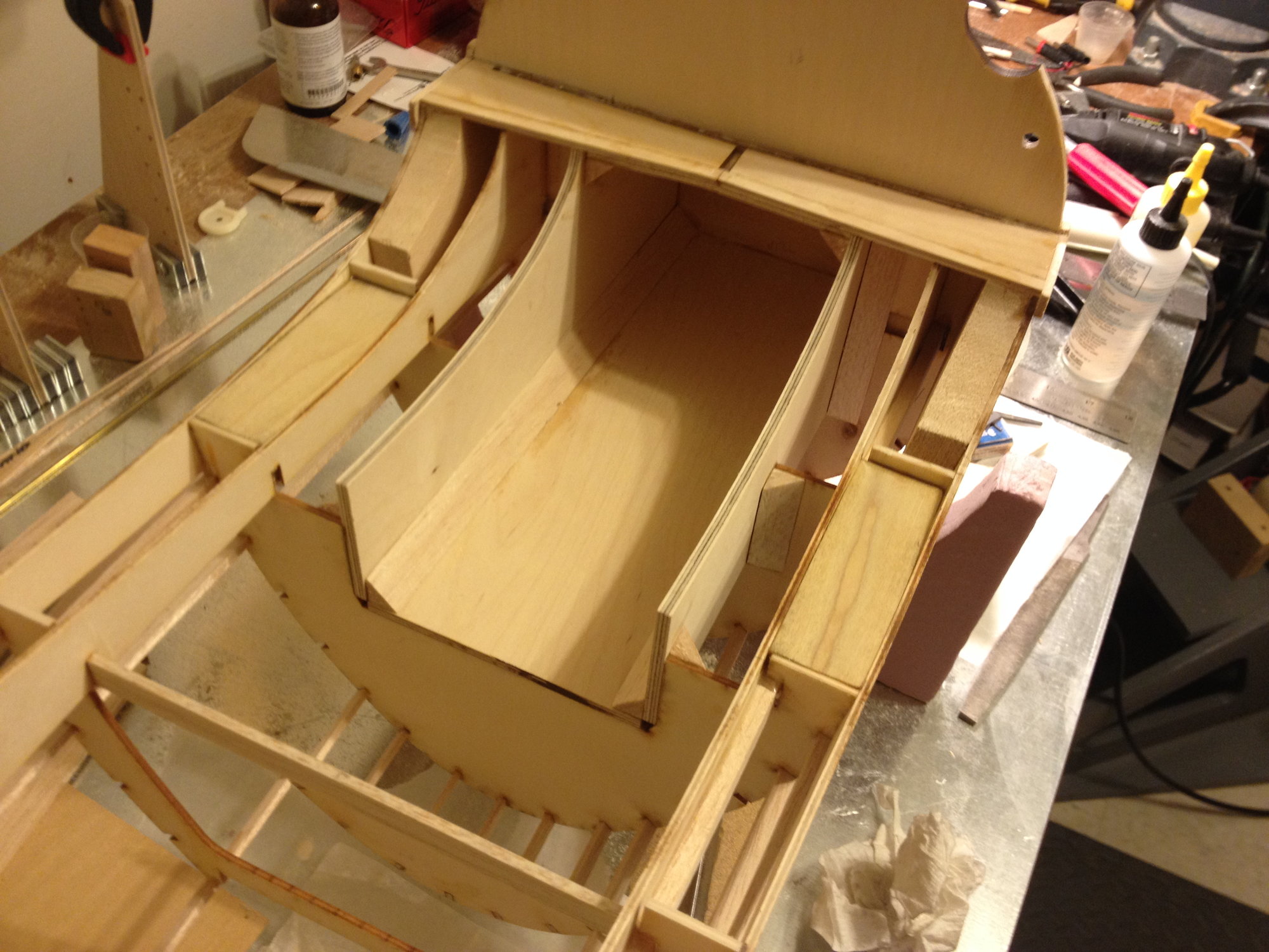
Lesson Learned - have all your parts before beginning one's build! I finally started reshaping the firewall to fit the Top-Flite cowling. Had to remove much of the sheeting forward of the cockpit. Also, several stringers had to be removed and the lite-ply longitudinal bits worked free from the firewall. Mounted the cowling, tracing the inside of it on the firewall, then using a bit of 1/8" sheeting to mark the line I'd have to sand down to. In a couple areas, I had to add material.
Also, I did get the new, custom exhaust from JTEC-RC . I don't have pictures, yet, as I need to finish this firewall task before putting the engine back on. Very nicely built - looks robust. As I will be off work for a couple weeks, soon, I think I'll throw it on my test stand, then, and see how it sounds.
Below, the left side of the fuse, showing a 1/8" gap between the firewall and the cowling. When I re-sheet this section, the sheeting will be a little bit below the cowling, allowing room for fiberglass and paint to bring it flush. What a pain, but it's starting to look like the cowlingn and firewall are meant for each other.
Here, the one can see how the sheeting looks installed on the reshaped firewall. I have the access hatch installed, on offset hinges.
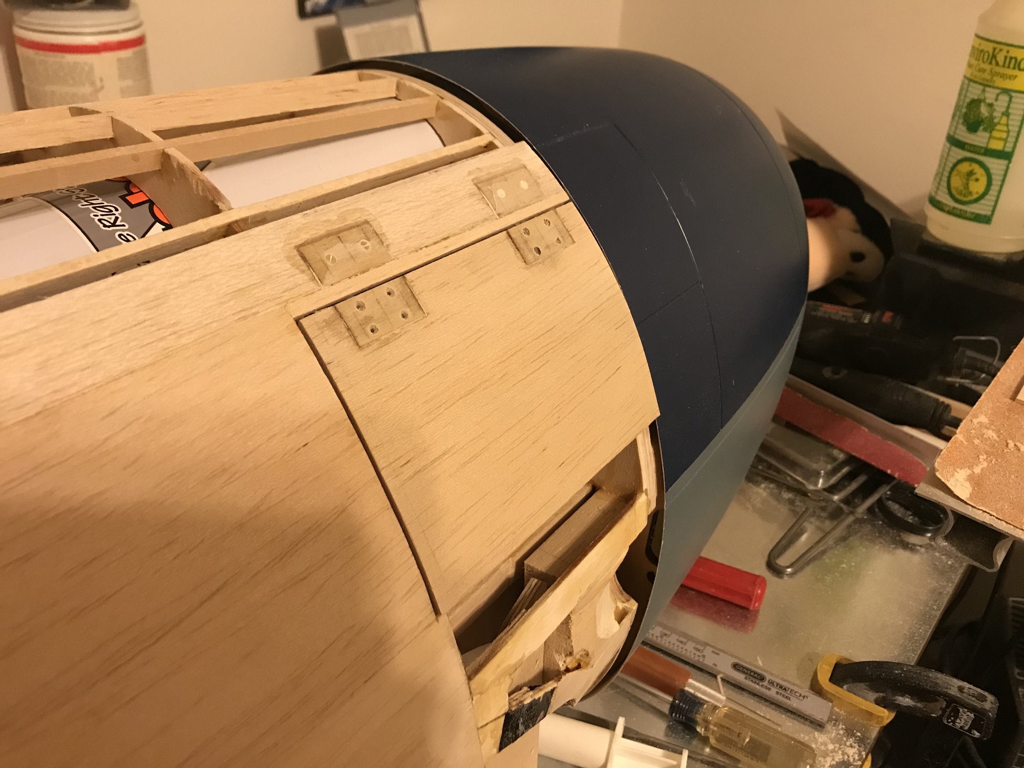
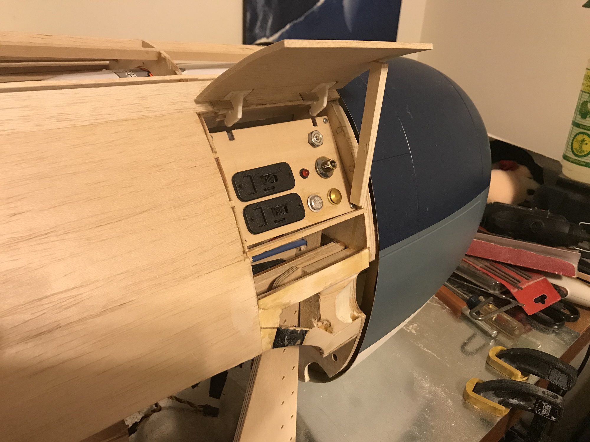
View with access hatch open. The hardest bits of this firewall reshaping task are behind me. Need to complete the re-sheeting, re-do the exhaust cut-outs and then reshape the belly pan/bottom of firewall to fit the cowl. I think that will then the hardest part of this whole build.
Lesson Learned - have all your parts before beginning one's build! I finally started reshaping the firewall to fit the Top-Flite cowling. Had to remove much of the sheeting forward of the cockpit. Also, several stringers had to be removed and the lite-ply longitudinal bits worked free from the firewall. Mounted the cowling, tracing the inside of it on the firewall, then using a bit of 1/8" sheeting to mark the line I'd have to sand down to. In a couple areas, I had to add material.
Also, I did get the new, custom exhaust from JTEC-RC . I don't have pictures, yet, as I need to finish this firewall task before putting the engine back on. Very nicely built - looks robust. As I will be off work for a couple weeks, soon, I think I'll throw it on my test stand, then, and see how it sounds.
Below, the left side of the fuse, showing a 1/8" gap between the firewall and the cowling. When I re-sheet this section, the sheeting will be a little bit below the cowling, allowing room for fiberglass and paint to bring it flush. What a pain, but it's starting to look like the cowlingn and firewall are meant for each other.
Here, the one can see how the sheeting looks installed on the reshaped firewall. I have the access hatch installed, on offset hinges.
View with access hatch open. The hardest bits of this firewall reshaping task are behind me. Need to complete the re-sheeting, re-do the exhaust cut-outs and then reshape the belly pan/bottom of firewall to fit the cowl. I think that will then the hardest part of this whole build.
Last edited by DaleCS; 04-17-2020 at 08:32 PM.
05-02-2020, 02:31 PM
#232
Thread Starter
Progress!
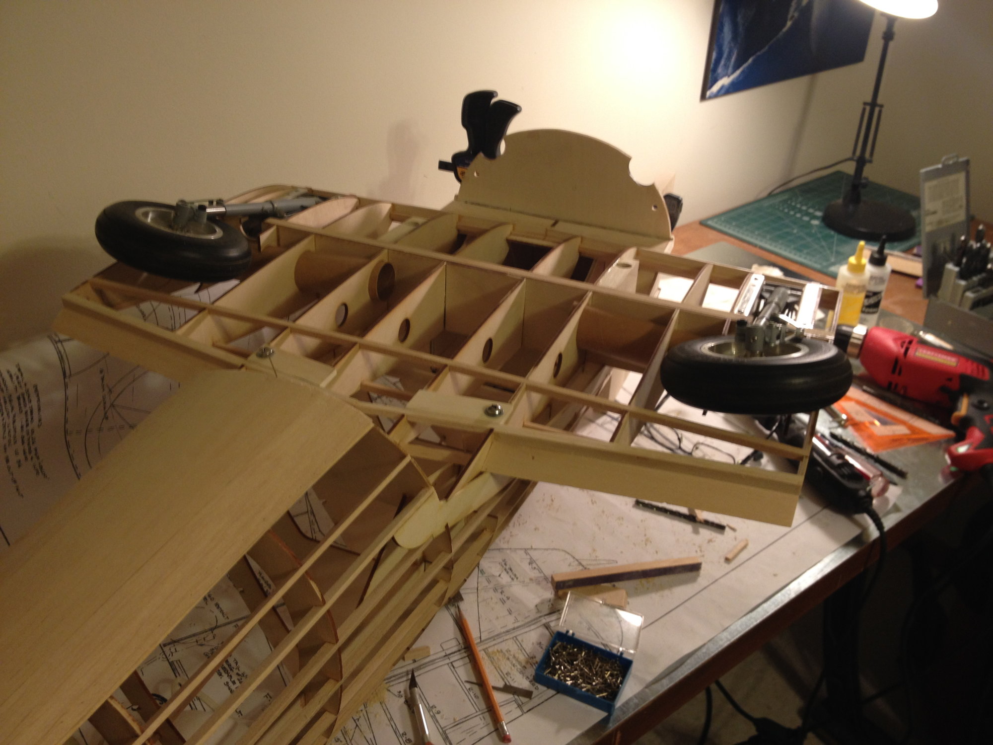
Cowling is mounted! Here, one can see that a bit of reshaping of the belly pan at the firewall is still required. The aircraft I'm planning to model this after had a replacement rudder from an earlier model F6F-3, with the tri-color paint scheme, showing that it had seen battle, been damaged and then repaired. I may carry this effect into the cowling - repainting it to match the rest of the 'deep sea blue' fuselage and wings but let some of the original tri-color scheme bleed through.
I used the 2 original cowling mount locations in the lower half of the Top-Flite Hellcat cowling. The mounting location at the top, noon position, had to be moved to the right a bit, say about 1 o'clock (pilots view) in order to clear the air cylinder that I mounted at the top, through the firewall. I first cut dowel stand-offs, drilling holes in them with a #7 drill. I then mounted these standoffs to the cowl ring, just using the drill bits through the cowl ring and into the stand-offs to hold them in place. Applied epoxy to the firewall side of the standoffs, slid the cowling into position and waited for the epoxy to cure. After removing the cowling, I tapped the standoffs through the firewall. This way, should the epoxy fail and the standoffs become loose, the bolts will still be secured in the firewall. Also, applied CA to the wood threads, to harden them up a bit. In the pic, the tap is shown in the upper, 1 o'clock mounting point, and black nylon bolt in the 4 o'clock position. Yes, the bolts are too long - they'll get cut down!
From the front view, bolts in both the 11 and 8 o'clock positions. Can also see the cut-out for the muffler pipes in the cowling. All this mounting is a lot easier in the Top-Flite kit, as it's all done by someone else!
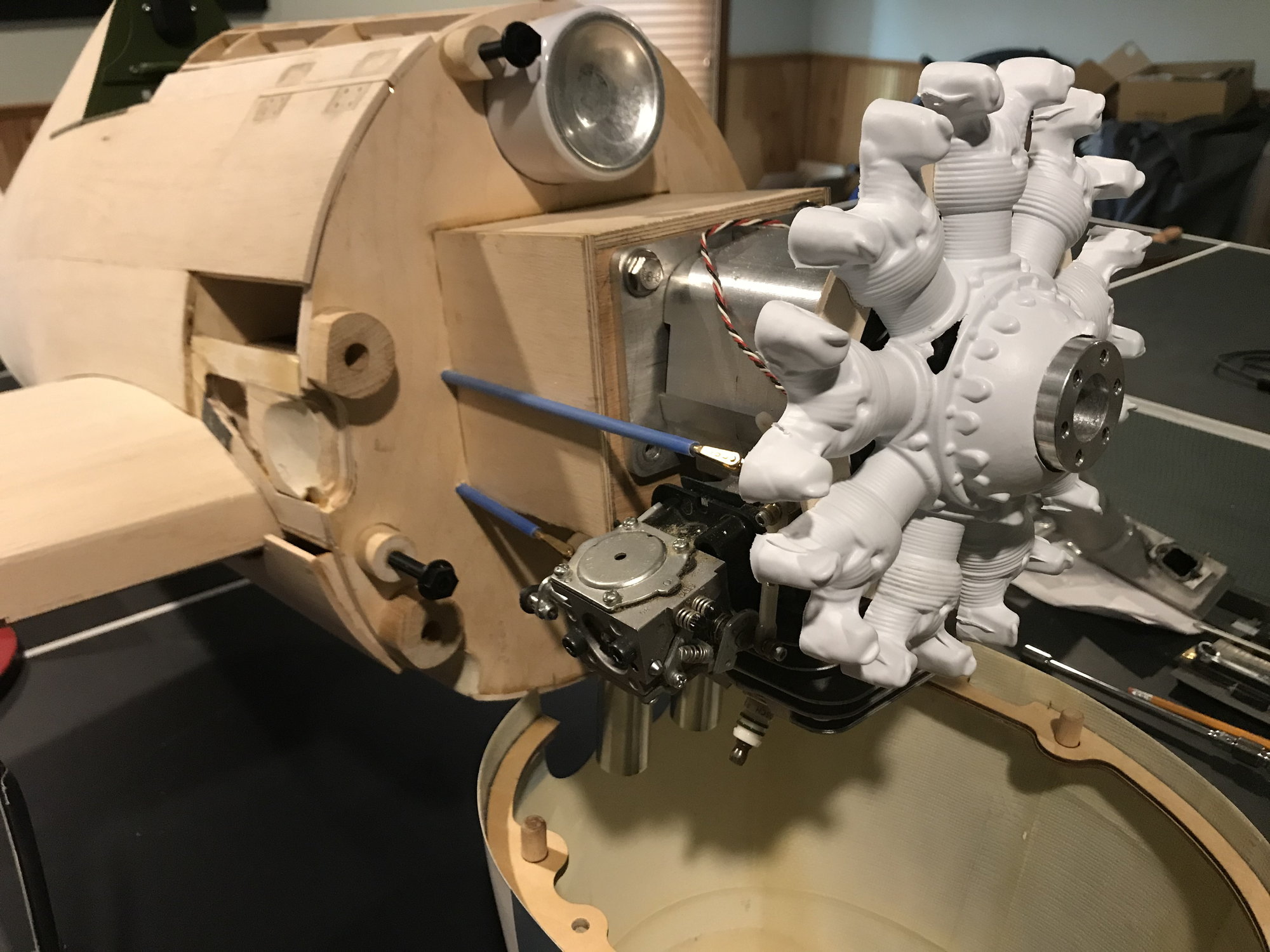
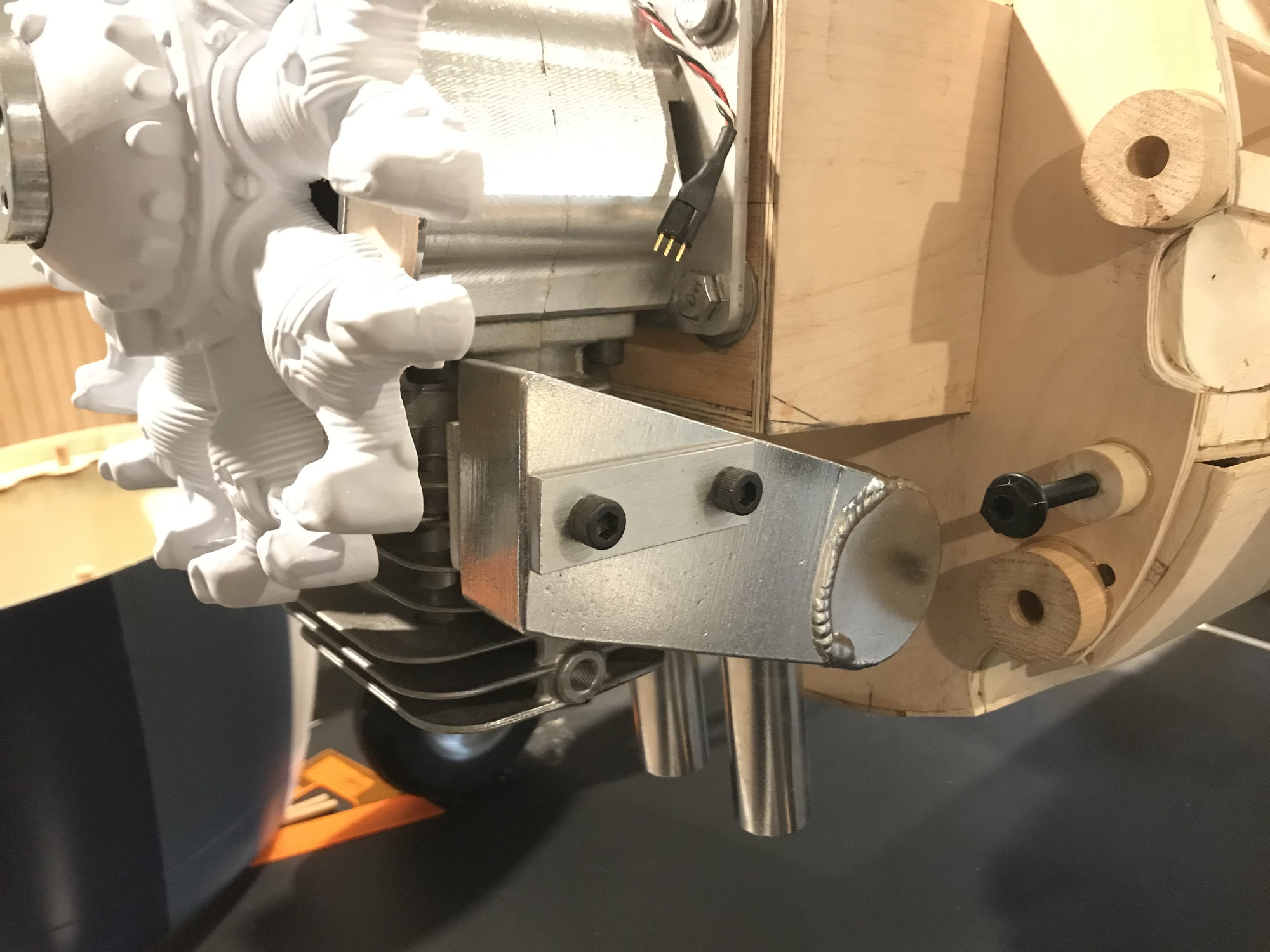
JTEC-RC custom Pitts muffler, attached. Why custom? Another outcome from not having all the parts at the start of the build. Obvious in this picture is that the engine is mounted about as far up on the engine box as it can go. This position gets the center line of the prop shaft centered in the cowling, where it should be. However, a standard Pitts muffler no longer fits, as the bottom of the engine box is in the way. I could have modified the engine box, but JTEC-RC said they could customize their standard design for a good price. I chose the easy route, as reshaping the firewall to fit the cowling is already enough rework! Also, in this pic, to the right of the black nylon cowl mounting bolt, one can see how much material I need to remove from the belly pan to fit the reshaped firewall and cowling.
That's all, for now!
Cowling is mounted! Here, one can see that a bit of reshaping of the belly pan at the firewall is still required. The aircraft I'm planning to model this after had a replacement rudder from an earlier model F6F-3, with the tri-color paint scheme, showing that it had seen battle, been damaged and then repaired. I may carry this effect into the cowling - repainting it to match the rest of the 'deep sea blue' fuselage and wings but let some of the original tri-color scheme bleed through.
I used the 2 original cowling mount locations in the lower half of the Top-Flite Hellcat cowling. The mounting location at the top, noon position, had to be moved to the right a bit, say about 1 o'clock (pilots view) in order to clear the air cylinder that I mounted at the top, through the firewall. I first cut dowel stand-offs, drilling holes in them with a #7 drill. I then mounted these standoffs to the cowl ring, just using the drill bits through the cowl ring and into the stand-offs to hold them in place. Applied epoxy to the firewall side of the standoffs, slid the cowling into position and waited for the epoxy to cure. After removing the cowling, I tapped the standoffs through the firewall. This way, should the epoxy fail and the standoffs become loose, the bolts will still be secured in the firewall. Also, applied CA to the wood threads, to harden them up a bit. In the pic, the tap is shown in the upper, 1 o'clock mounting point, and black nylon bolt in the 4 o'clock position. Yes, the bolts are too long - they'll get cut down!
From the front view, bolts in both the 11 and 8 o'clock positions. Can also see the cut-out for the muffler pipes in the cowling. All this mounting is a lot easier in the Top-Flite kit, as it's all done by someone else!
JTEC-RC custom Pitts muffler, attached. Why custom? Another outcome from not having all the parts at the start of the build. Obvious in this picture is that the engine is mounted about as far up on the engine box as it can go. This position gets the center line of the prop shaft centered in the cowling, where it should be. However, a standard Pitts muffler no longer fits, as the bottom of the engine box is in the way. I could have modified the engine box, but JTEC-RC said they could customize their standard design for a good price. I chose the easy route, as reshaping the firewall to fit the cowling is already enough rework! Also, in this pic, to the right of the black nylon cowl mounting bolt, one can see how much material I need to remove from the belly pan to fit the reshaped firewall and cowling.
That's all, for now!
 05-08-2020, 09:53 AM
#234
Thread Starter
Hello 'ledd4u'!
I built the wing in 3 sections - center with two removable outer panels. I prefer this method for transport reasons, as I can simply set the fuse/center section in my Jeep with the wheels down and go. Mounting blocks are installed per drawings, as shown in pictures, below. Currently using 1/4-20 stainless bolts.
Let me know if this info answered your question well enough.
Front wing mount blocks installed in fuselage.
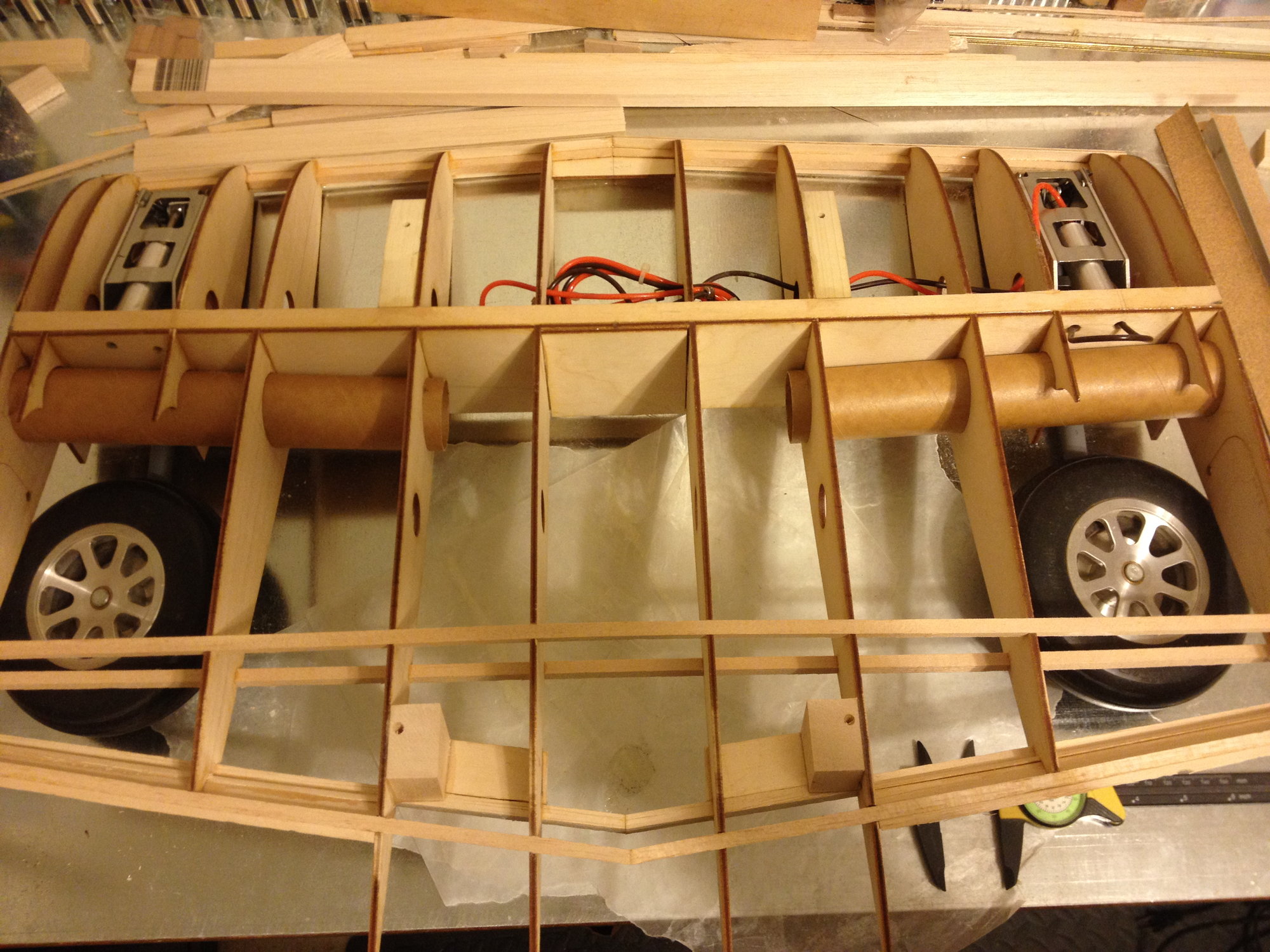
Front and rear wing mount blocks installed in wing.
Center wing section mounted to fuse. Can see head of 1/4-20 bolts in rear mount positions.
Front and rear wing mounts in fuse, drilled. Blind 1/4-20 nuts (not visible) on top sides of mounting blocks.
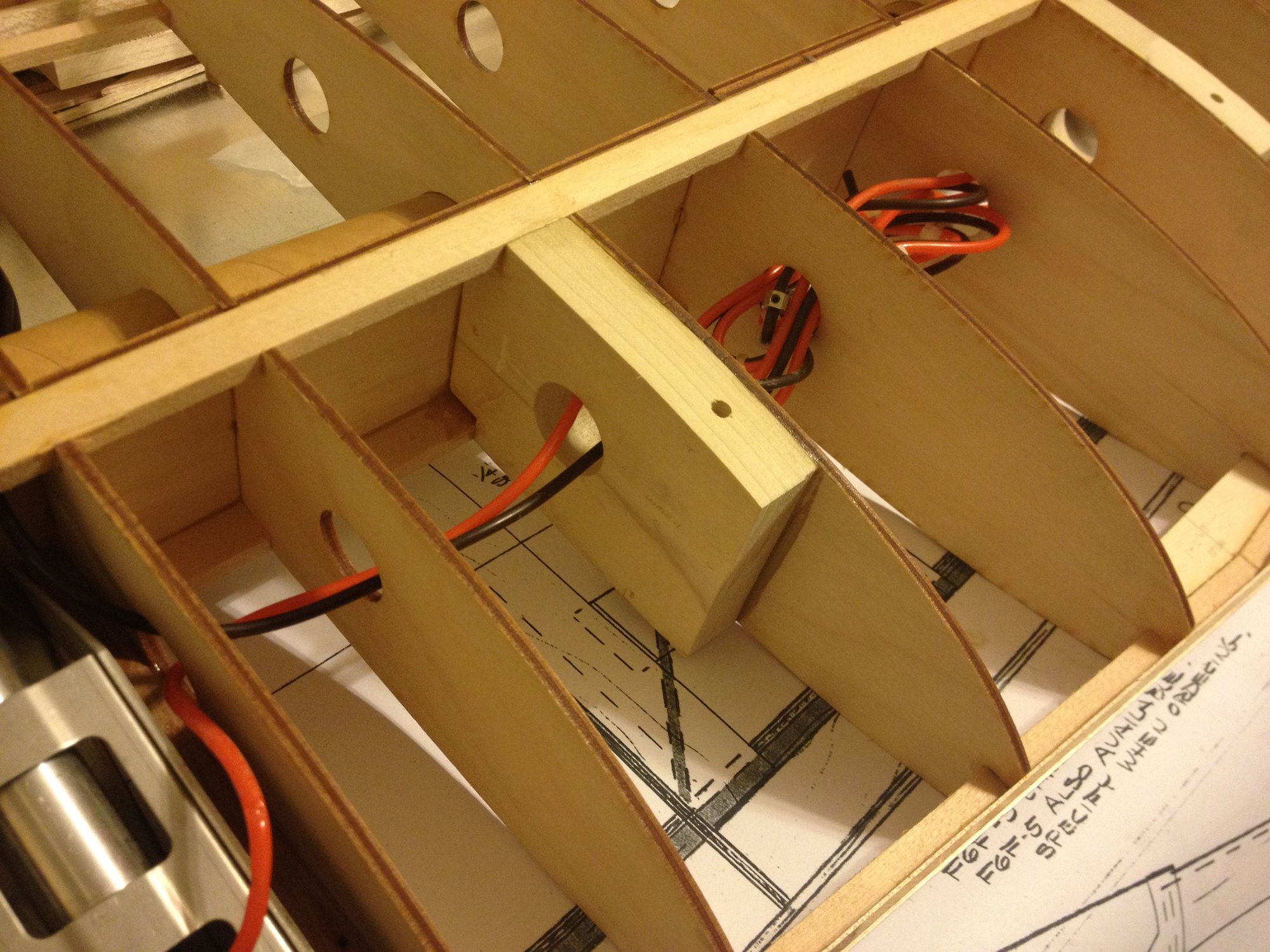
Top view showing the left wing front mount block - notches to fit between wing spars, cable/hose through hole and bolt hole. Bolt hole is counter bored from bottom.
Bottom view, left wing front mount showing counter bore.
I built the wing in 3 sections - center with two removable outer panels. I prefer this method for transport reasons, as I can simply set the fuse/center section in my Jeep with the wheels down and go. Mounting blocks are installed per drawings, as shown in pictures, below. Currently using 1/4-20 stainless bolts.
Let me know if this info answered your question well enough.
Front wing mount blocks installed in fuselage.
Front and rear wing mount blocks installed in wing.
Center wing section mounted to fuse. Can see head of 1/4-20 bolts in rear mount positions.
Front and rear wing mounts in fuse, drilled. Blind 1/4-20 nuts (not visible) on top sides of mounting blocks.
Top view showing the left wing front mount block - notches to fit between wing spars, cable/hose through hole and bolt hole. Bolt hole is counter bored from bottom.
Bottom view, left wing front mount showing counter bore.
 05-09-2020, 04:58 PM
#236
Thread Starter
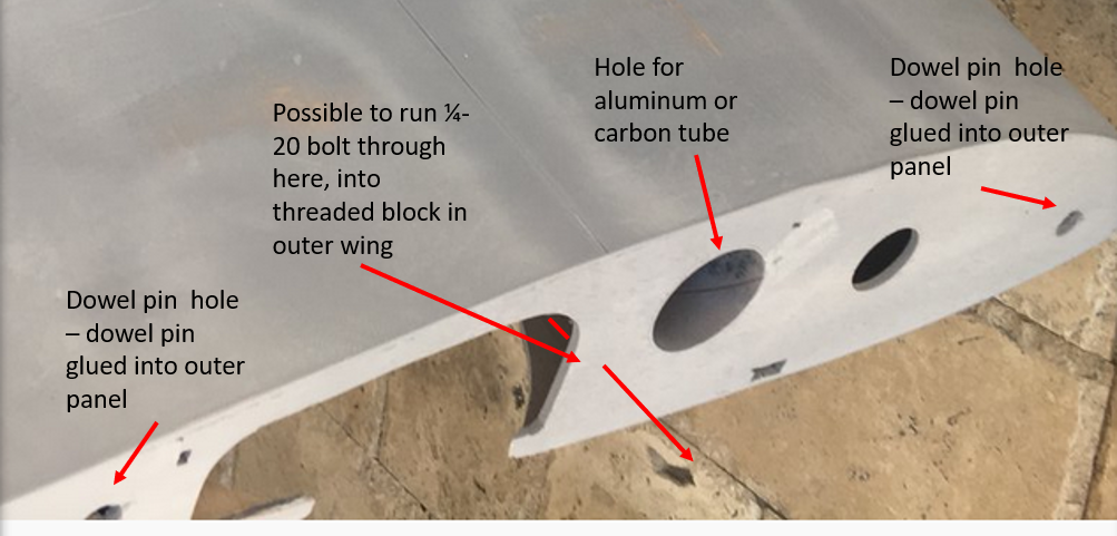
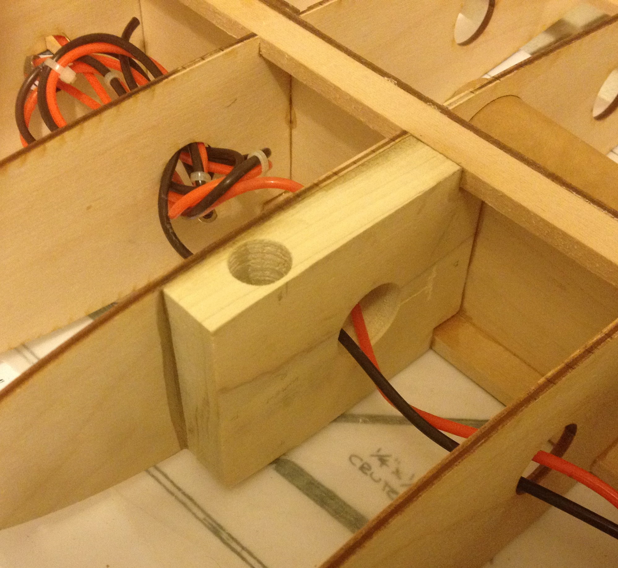
If using an aluminum tube, one can fit a wood block into each end of the tube, drill a hole through the cardboard tube holder, through the aluminum tube and into the block. Then tap the block for your fastener. Not sure on carbon fiber tubes, which I have - have read concerns about the drilled hole creating a weak spot in the carbon that can propagate cracks. Don't quote me on this. I need to do so more research, and if true, figure out another way to secure the carbon tube or switch to aluminum. I don't want to glue tube into the outer panels - if damaged in any way, removal/replacement could get rather destructive.
On my Byron, I installed a secondary attachment, indicated in the picture, above. I installed a ply plate on the inboard portion of the wing and a wood block on the outboard panel. I then drilled a hole through the two, tapping the block in the outer panel. The 1/4-20 bolt could be inserted and tightened/loosened through the wheel well. I don't consider this to be a primary method to secure the wing panels - just a backup. I like my wings attached - a bit of redundancy is comforting.
I'll look through some old pics to see if I have an example of it.
In the meantime, if others have ideas, please add to this discussion!
Last edited by DaleCS; 05-09-2020 at 05:57 PM.
05-14-2020, 04:45 PM
#238
Thread Starter
Sorry - went through all my pictures from my Byron and didn't find anything regarding the 'bolt through the ribs' method for securing wing. I've also not finished this step on my Hellcat, yet. Probably will do this after I've mounted the belly pan to the wing center section and finished re-sheeting the front of the fuse (i.e. "it will be awhile"). However, I think I may beef up this wing attachment method over what I used on the Byron, and consider it my primary attachment. I don't expect to be doing snap-rolls, so it shouldn't take much to keep 'em on.
 05-15-2020, 03:46 AM
#241
My Feedback: (23)
Perfect! Screw the dowel crap! Thanks man I appreciate it and saves me a trip to The Home Depot aka �COVID19 Home Center�!
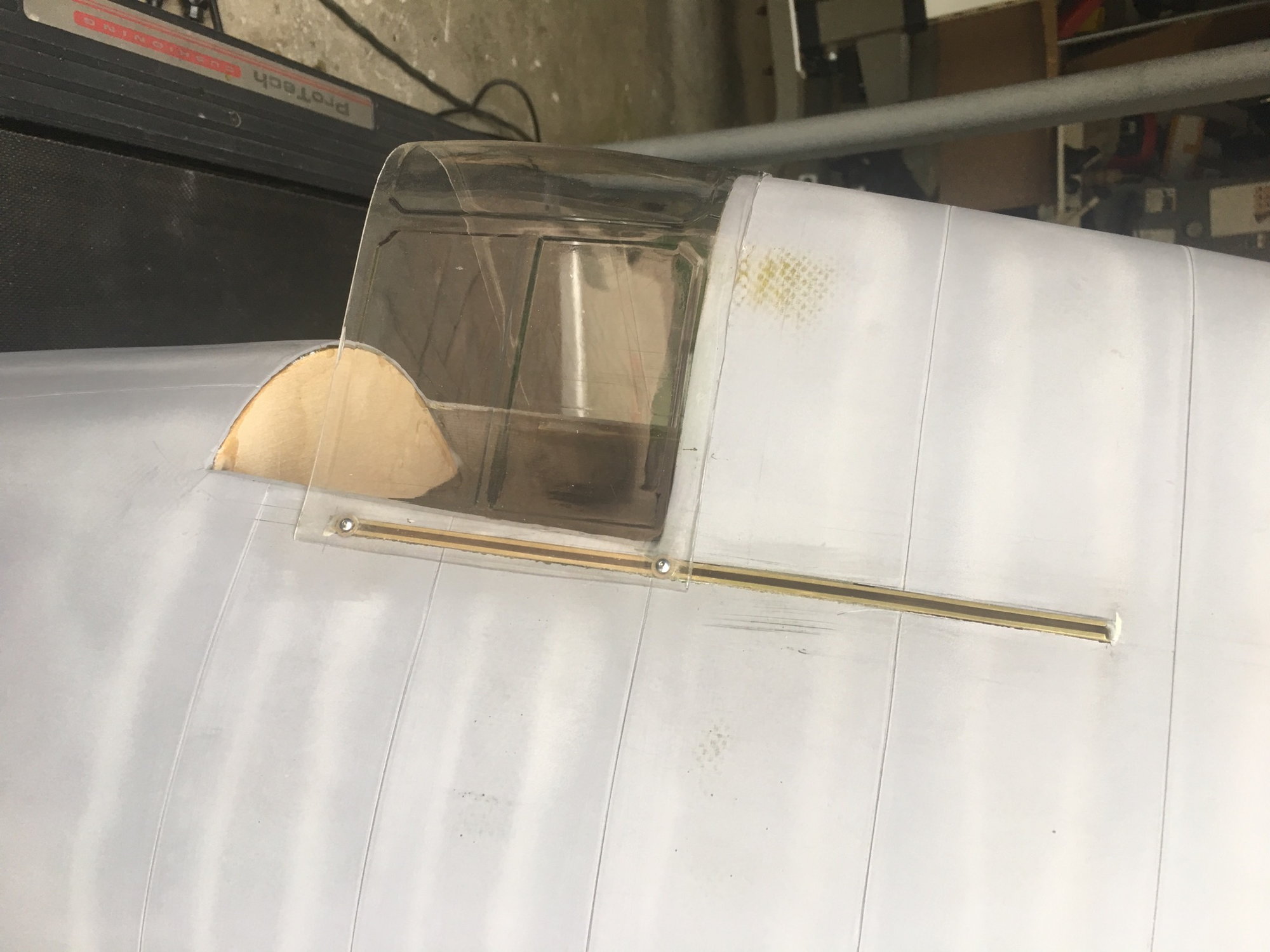
preliminary completion of sliding canopy. Ordered the NZ modeler detail kit awaiting arrival. Doing odds and ends. Panel lines all completed. Canopy will have to be reinforced with carbon fiber tape so that it�s more rigid. I used 3/16 square stock and cut my own slit with a jig.
preliminary completion of sliding canopy. Ordered the NZ modeler detail kit awaiting arrival. Doing odds and ends. Panel lines all completed. Canopy will have to be reinforced with carbon fiber tape so that it�s more rigid. I used 3/16 square stock and cut my own slit with a jig.
Last edited by ledd4u; 05-15-2020 at 04:50 AM.
05-24-2020, 07:34 AM
#242
Thread Starter
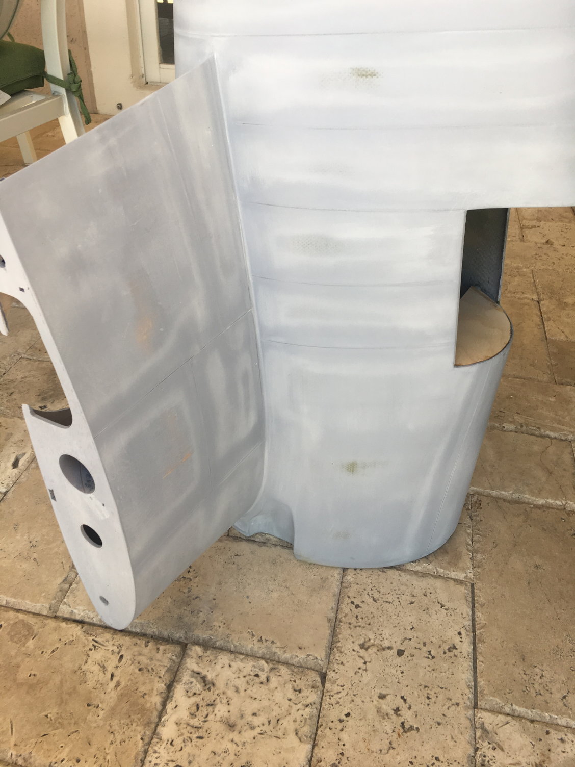
Exactly - that's the way to do it. My only difference is that I have a phenolic sleeve glued into the wing, that the carbon fiber tube then slides into - with 'stops' glued into the end of the phenolic sleeve. That way, if I ever crack/damage the carbon tube, I won't have to disassemble the wing. Will post a new pic when I've got the wing attachment nut/bolt installed. Currently, I think I've resolved my belly pan mounting dilemma solved - at least the concept is my head and appears to be the simplest approach, for me. Will post a picture of that, when implemented.
05-24-2020, 07:44 AM
#243
Thread Starter
Perfect! Screw the dowel crap! Thanks man I appreciate it and saves me a trip to The Home Depot aka �COVID19 Home Center�!
preliminary completion of sliding canopy. Ordered the NZ modeler detail kit awaiting arrival. Doing odds and ends. Panel lines all completed. Canopy will have to be reinforced with carbon fiber tape so that it�s more rigid. I used 3/16 square stock and cut my own slit with a jig.
preliminary completion of sliding canopy. Ordered the NZ modeler detail kit awaiting arrival. Doing odds and ends. Panel lines all completed. Canopy will have to be reinforced with carbon fiber tape so that it�s more rigid. I used 3/16 square stock and cut my own slit with a jig.
05-24-2020, 09:43 AM
#244
Thread Starter
So, my dilemma - how to design/fit mounting blocks to the center wing section, that conform to the belly pan's shape, it's formers/stringers....after the wing and belly pan are built! The thought of cut/sanding/shaping these mounting blocks, and then mounting them to the center section perfectly so that the belly pan lines up perfectly with the fuse - this was all driving me nuts.
Remembering Achim's razor ("entities should not be multiplied without necessity"), I kept searching for the simplest answer. What's the easiest way to get something to conform to such a space? Use a conformable material! What do I have on hand? Comi-con modeling foam? Yes, but not resilient enough. Epoxy and micro-balloons? YES!
I don't know if this is an original idea or not, but I did what I thought was an exhaustive search on belly pan mounting options, finding none helpful to my "after everything built" situation. (I did find magnets, but had concerns confirmed by another Hellcat builder/pilot, regarding separation in flight - perhaps due to airframe flex causing air gap increases between the magnets.)
Hope others find this useful.
Another good point, I think, about this solution is that I'll be able to counter sink the attachment screws for a flush fit. Paint the head of the attachment screws and they will "disappear."
Solution:
Here's the box I created on the rear, left hand portion of the belly pan, filled with epoxy/micro-balloon mixture, with the box top ready to go on, off to the right.
Rear, left box covered (bottom right of picture) and the front right also covered, with a scrap block of wood sitting on it. Basically, all I have to do is draw a line on the block, cut it and it's ready to be glued to the center-wing section. How easy is that?!
Remembering Achim's razor ("entities should not be multiplied without necessity"), I kept searching for the simplest answer. What's the easiest way to get something to conform to such a space? Use a conformable material! What do I have on hand? Comi-con modeling foam? Yes, but not resilient enough. Epoxy and micro-balloons? YES!
I don't know if this is an original idea or not, but I did what I thought was an exhaustive search on belly pan mounting options, finding none helpful to my "after everything built" situation. (I did find magnets, but had concerns confirmed by another Hellcat builder/pilot, regarding separation in flight - perhaps due to airframe flex causing air gap increases between the magnets.)
Hope others find this useful.
Another good point, I think, about this solution is that I'll be able to counter sink the attachment screws for a flush fit. Paint the head of the attachment screws and they will "disappear."
Solution:
- Fit/glue a bit of filler wood between the stringers to create 4 boxes in the belly pan
- Make a top for each box
- Support the belly pan so that the top of the box is perpendicular to gravity (one side at a time)
- Fill two boxes with a mixture of epoxy/micro-baloons
- Put the box tops in place, cleaning up any excess filler that oozes out
- Repeat 2-5 for the other side
- Rough cut a block of hardwood and place on top of the box
- Mark it, cut it
- Temp glue/tape the block in place
- Drill through the belly pan, the center of the box and into the hardwood block
- Insert the screw that will be used to hold the belly pan in place
- Remove the temp/glue
- Apply epoxy to the top the hardwood blocks
- Position the belly pan over the center section, aligning it with the fuse
- Let the epoxy set
- Remove the screws and drop the belly pan
- Repeat 7-16 for the other 3 attachment points.
- Want 6 attachment points? Go for it - just repeat the steps as necessary.
Here's the box I created on the rear, left hand portion of the belly pan, filled with epoxy/micro-balloon mixture, with the box top ready to go on, off to the right.
Rear, left box covered (bottom right of picture) and the front right also covered, with a scrap block of wood sitting on it. Basically, all I have to do is draw a line on the block, cut it and it's ready to be glued to the center-wing section. How easy is that?!
Last edited by DaleCS; 05-24-2020 at 09:56 AM.
06-06-2020, 10:10 AM
#245
Thread Starter
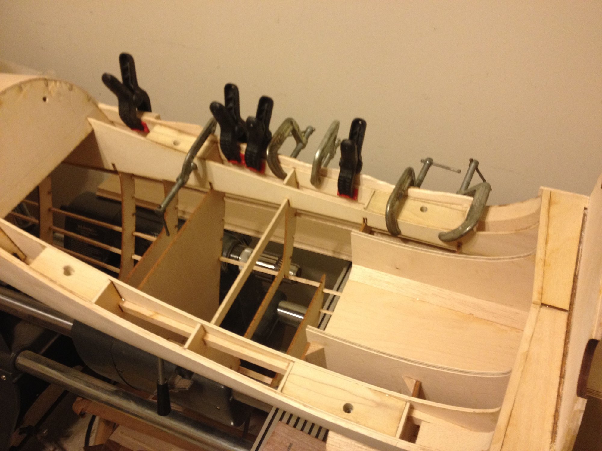
Belly pan mounting blocks made - basically, completed steps 1-8 of my plan:
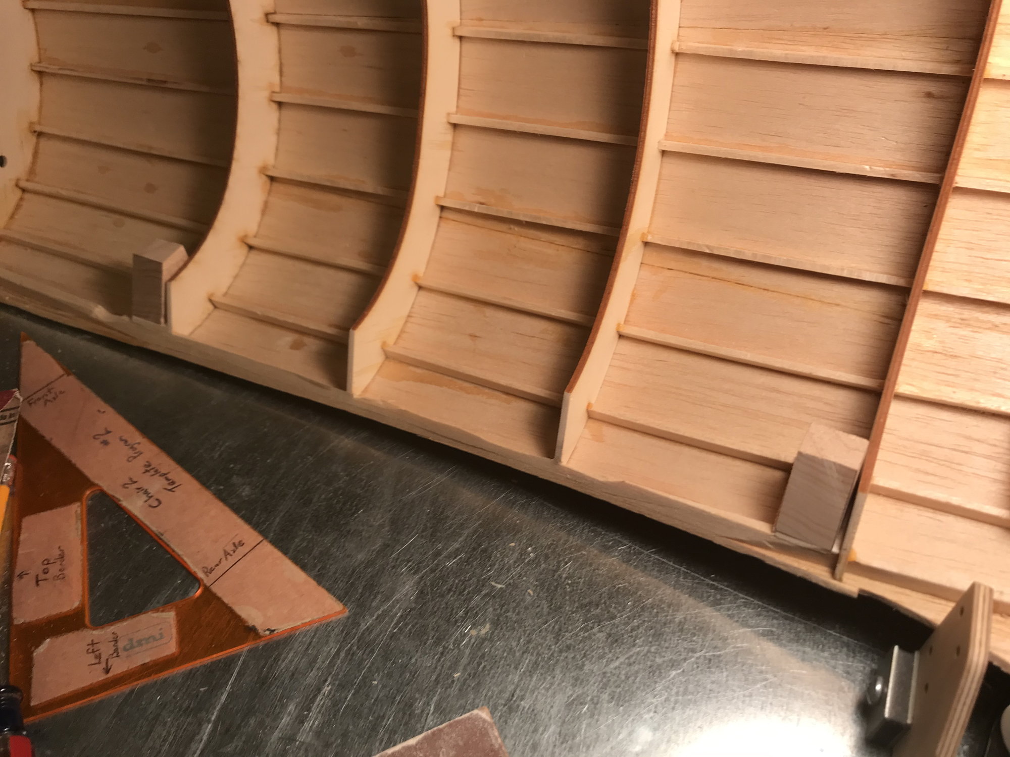
By laying a flat edge across the curved edge that meets the wing, I can turn the blocks to match the wings curvature.
By laying a flat edge across the curved edge that meets the wing, I can turn the blocks to match the wings curvature.
06-23-2020, 03:00 PM
#246
Thread Starter
Belly pan is mounted! Hooray! Steps 9-17 in my 'belly pan' attachment list completed, today. Actually, rather than epoxying each block in place, one at a time (just in case I screwed up, I'd have less undo/redoing to do), I just went for it and did all 4 blocks at the same time. However, I added a check step to my list.
I used some modeling foam, thinning it out and placing on the top of each block. Then, put the belly pan in place, pressing down to squeeze it out as much as possible (I had the fuse upside down, supported by the carbon wing tubes). Removing the pan, I could then see how much of the front blocks were hitting the balsa sheet vs. hanging in air, and I was able to check the thickness of the squeezed foam - did my method leave an air gap, or did the blocks sit on the wing sheeting? All good.
I also strategically placed wax paper at points where the epoxy might squeeze out, to ensure I didn't glue the pan itself to the center wing section. One the epoxy set, I pulled the screws and the pan lifted off perfectly.
This was the last of my big, show stopper challenges.
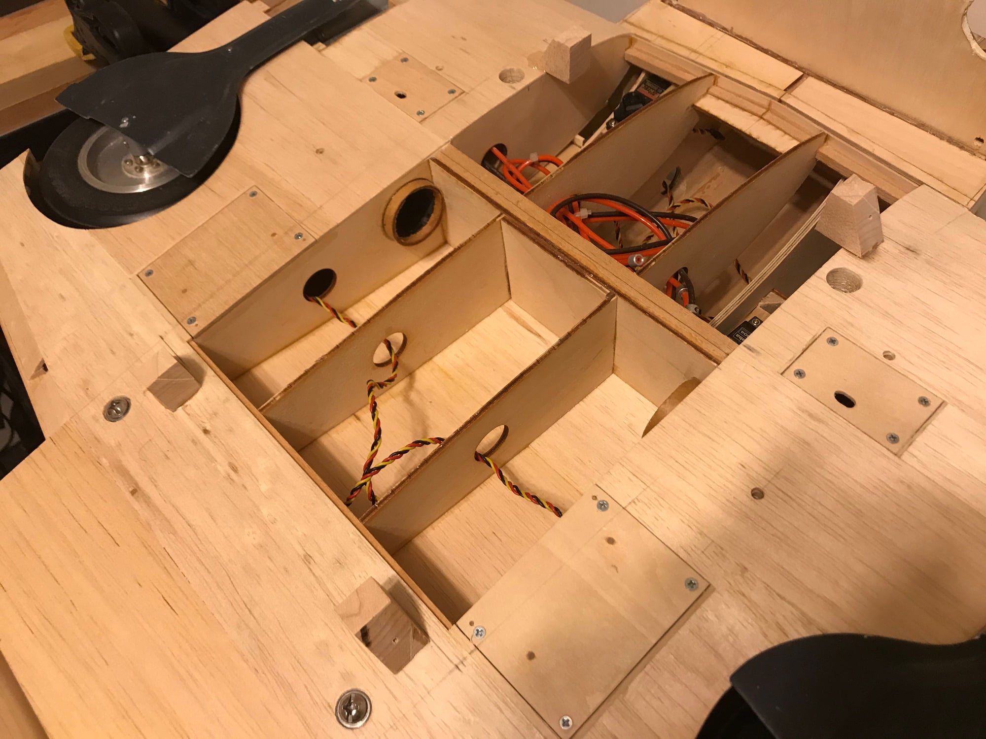
Yes, the front mounting blocks are a bit precarious. I wanted to leave the center section as open as possible, for passing wires, hoses, possibly (later) installing a smoke pump and tank...open leaves options. I have some 1/8" bass wood sheeting - will make strips of sheeting that go across ribs 1 ad 2, under the mounting blocks, or one strip that goes from left rib 2 t right rib 2. I think I'll also run a screw through this strip into each block and add some reinforcing triangular stock.
I also need to get some longer screws - the 3/4" screws I'm using, now, may be fine to hold the pan in place, but I'm planning to mount an external, drop-able tank - another 1/4" longer would put a full 1/2" of screw into both epoxy filler in the pan sidewalls and the hardwood mounts.
4 screws, flush. Happy-happy!
I used some modeling foam, thinning it out and placing on the top of each block. Then, put the belly pan in place, pressing down to squeeze it out as much as possible (I had the fuse upside down, supported by the carbon wing tubes). Removing the pan, I could then see how much of the front blocks were hitting the balsa sheet vs. hanging in air, and I was able to check the thickness of the squeezed foam - did my method leave an air gap, or did the blocks sit on the wing sheeting? All good.
I also strategically placed wax paper at points where the epoxy might squeeze out, to ensure I didn't glue the pan itself to the center wing section. One the epoxy set, I pulled the screws and the pan lifted off perfectly.
This was the last of my big, show stopper challenges.
Yes, the front mounting blocks are a bit precarious. I wanted to leave the center section as open as possible, for passing wires, hoses, possibly (later) installing a smoke pump and tank...open leaves options. I have some 1/8" bass wood sheeting - will make strips of sheeting that go across ribs 1 ad 2, under the mounting blocks, or one strip that goes from left rib 2 t right rib 2. I think I'll also run a screw through this strip into each block and add some reinforcing triangular stock.
I also need to get some longer screws - the 3/4" screws I'm using, now, may be fine to hold the pan in place, but I'm planning to mount an external, drop-able tank - another 1/4" longer would put a full 1/2" of screw into both epoxy filler in the pan sidewalls and the hardwood mounts.
4 screws, flush. Happy-happy!
06-27-2020, 02:54 PM
#247
Thread Starter
Right wing barrels rough mounted, aimed and tested.
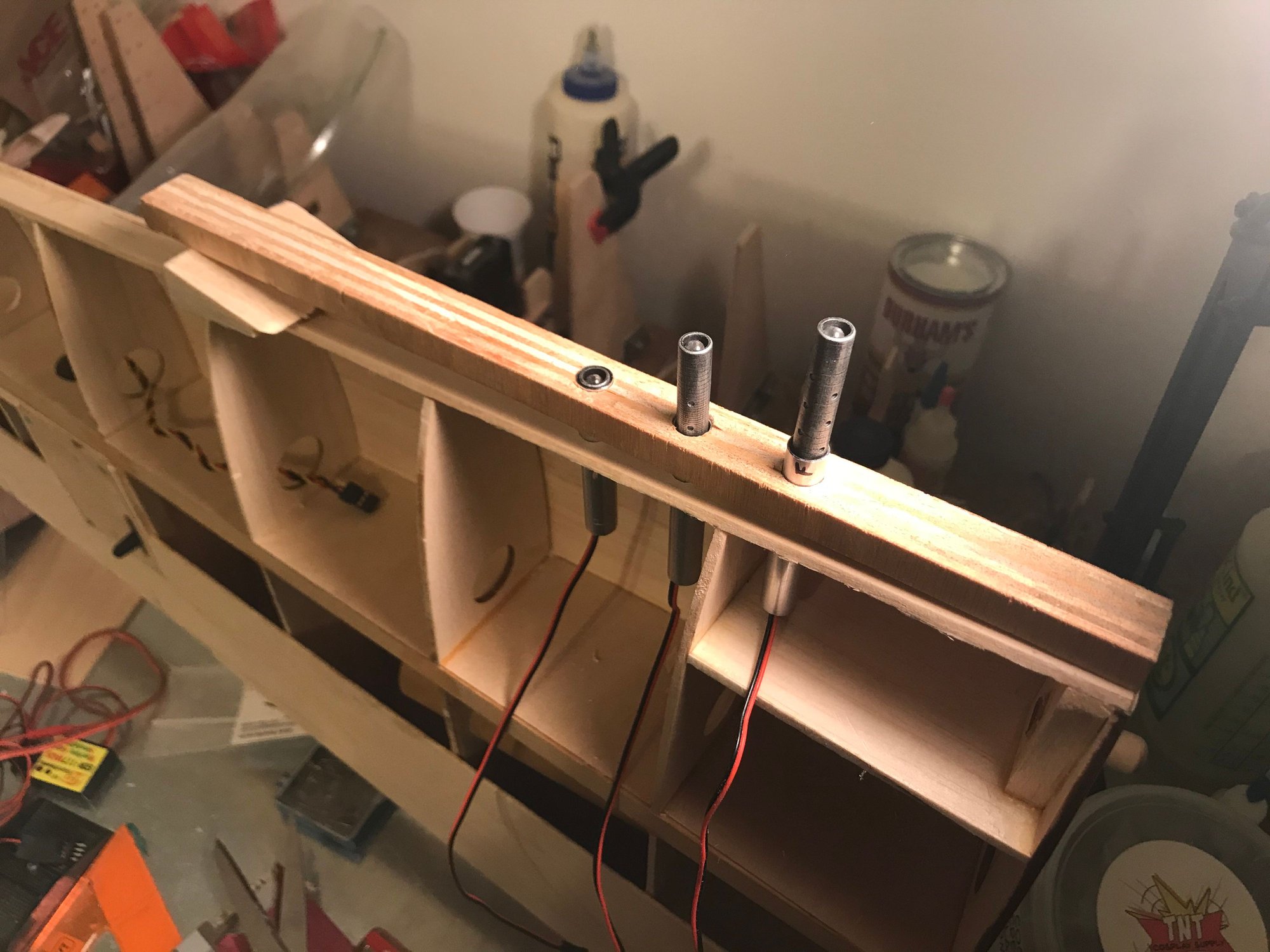
Used a scrap piece of wood to make a template for drilling the holes. By lifting the outer end of the template, I can set the convergence angle (roughly!). Used the later WWII setting of 1000'. How close are my settings? Good enough! Barrels are from IFlyTailies. I went with the premium (painted) set and had them custom drilled to accept the LEDs.
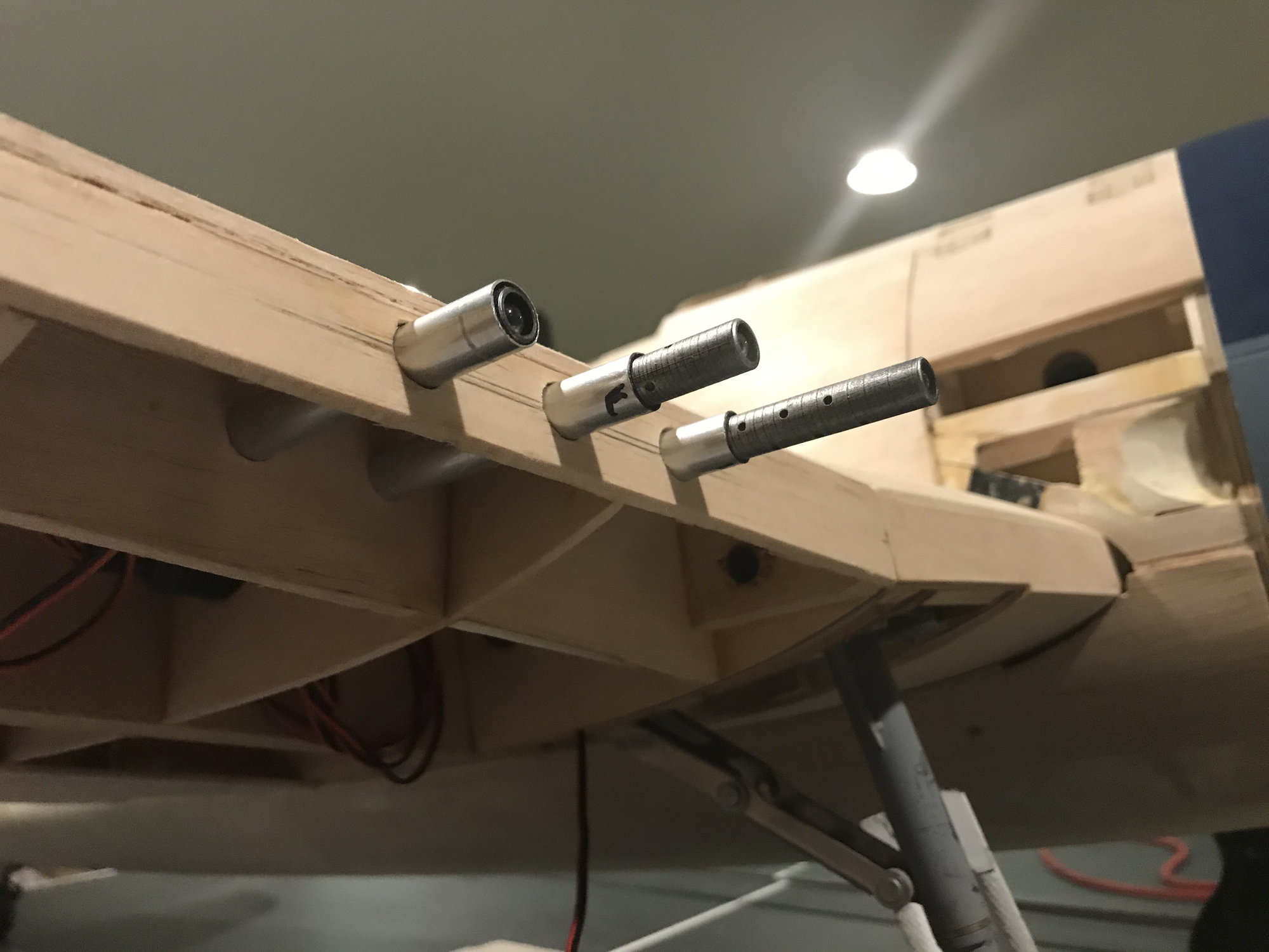
I still have to sheet the bottom of the wing, make an access cover and install/shape the leading edge. Note that I have the barrels inside an aluminum sleeve. I thought this would give me a crisper looking hole for the barrel to come through, vs. balsa. Also, the ID of the aluminum tube is a bit bigger than the barrel. I wrap the barrels with some tape to get an interference fit, and the barrel is then centered in the tube. I think this will look very good when all is done.
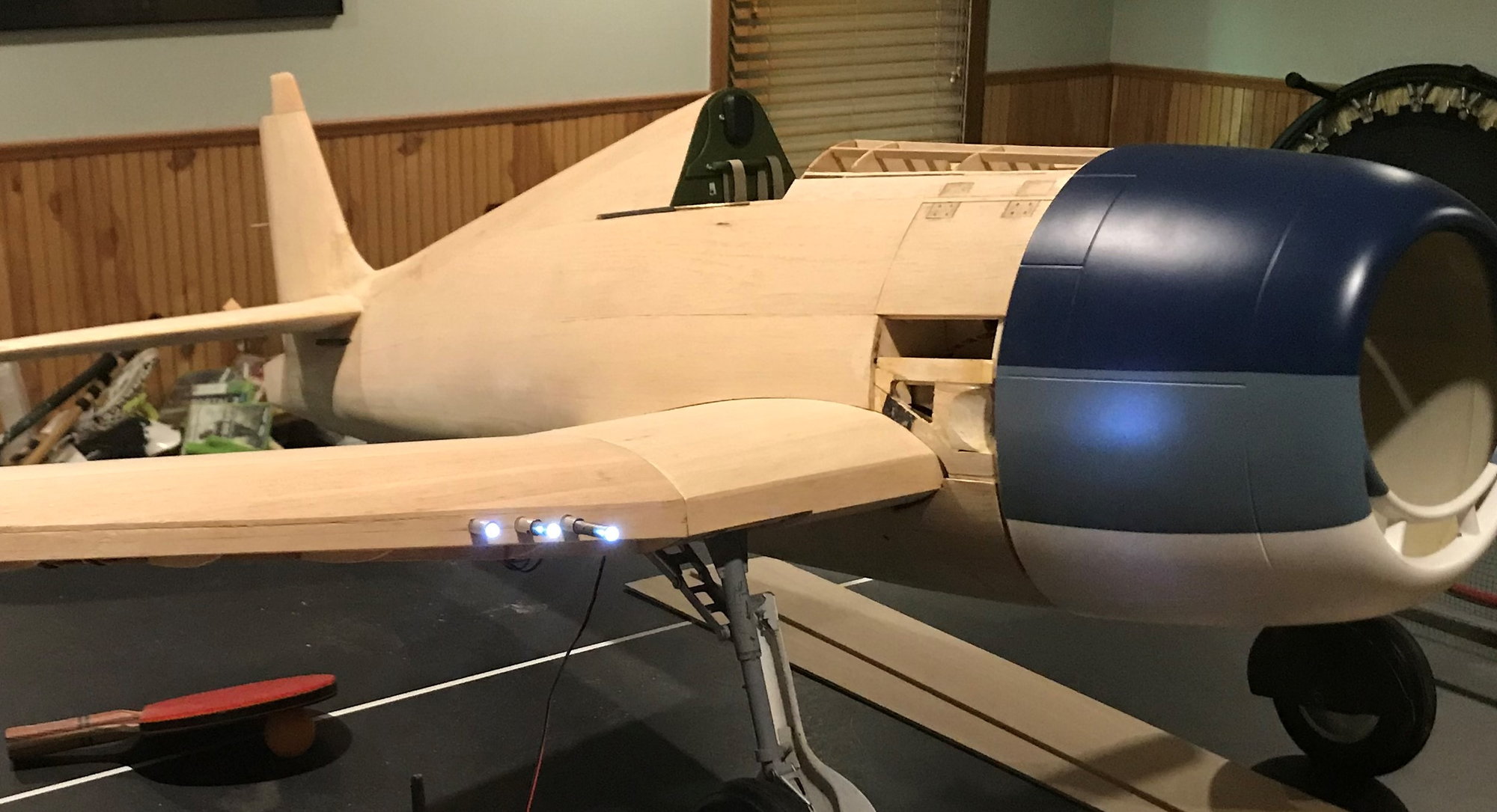
Testing on the range!
Very bright when straight on - should have no trouble seeing these during flight. Thanks to the LEDs and controller from ElectroDynamics! Super Chipmunk is serving as an APU for this test.
Used a scrap piece of wood to make a template for drilling the holes. By lifting the outer end of the template, I can set the convergence angle (roughly!). Used the later WWII setting of 1000'. How close are my settings? Good enough! Barrels are from IFlyTailies. I went with the premium (painted) set and had them custom drilled to accept the LEDs.
I still have to sheet the bottom of the wing, make an access cover and install/shape the leading edge. Note that I have the barrels inside an aluminum sleeve. I thought this would give me a crisper looking hole for the barrel to come through, vs. balsa. Also, the ID of the aluminum tube is a bit bigger than the barrel. I wrap the barrels with some tape to get an interference fit, and the barrel is then centered in the tube. I think this will look very good when all is done.
Testing on the range!
Very bright when straight on - should have no trouble seeing these during flight. Thanks to the LEDs and controller from ElectroDynamics! Super Chipmunk is serving as an APU for this test.
Last edited by DaleCS; 06-28-2020 at 10:17 AM.
06-28-2020, 03:15 PM
#248
Thread Starter
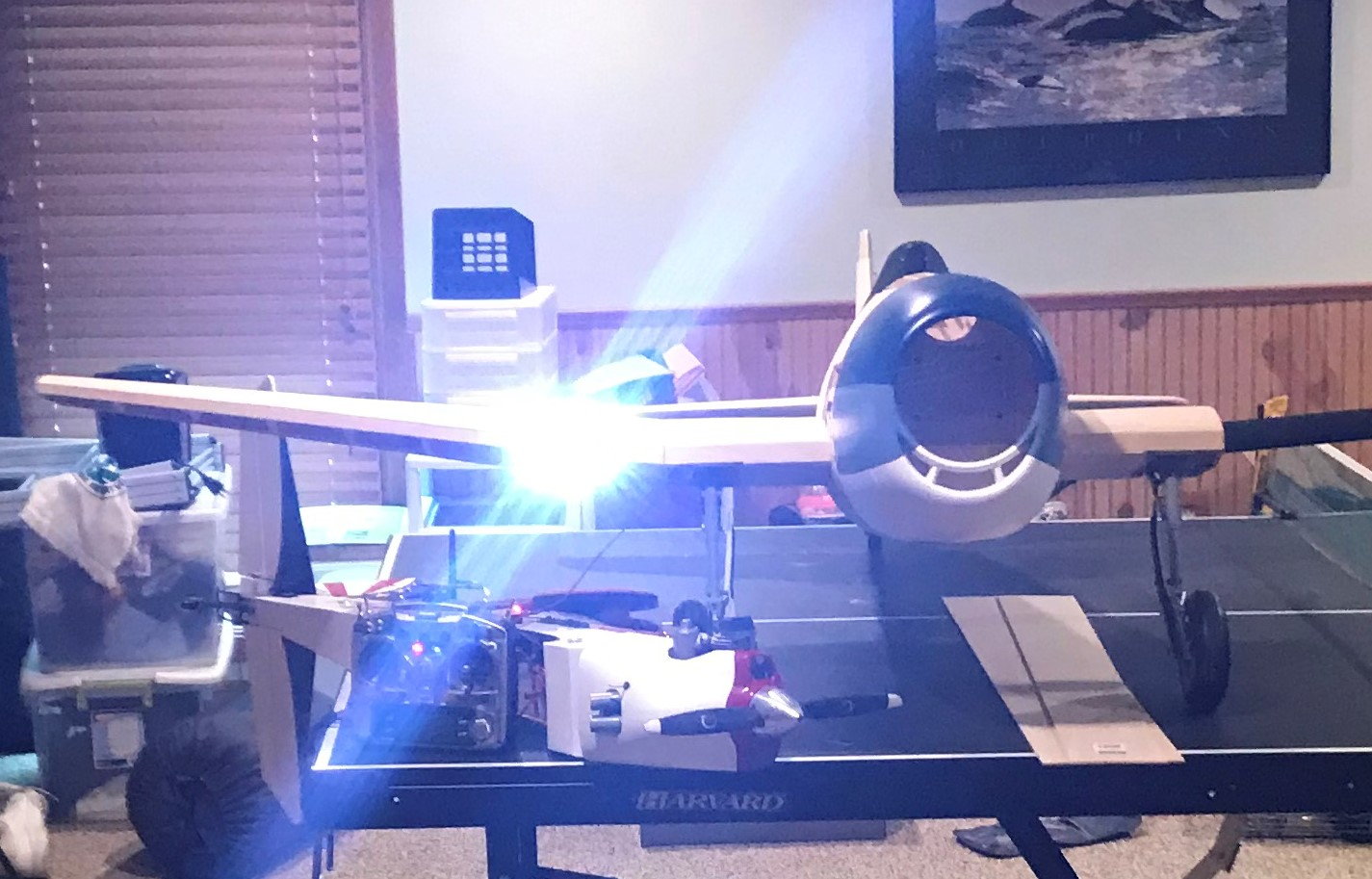
Barrels mounted on both wings!
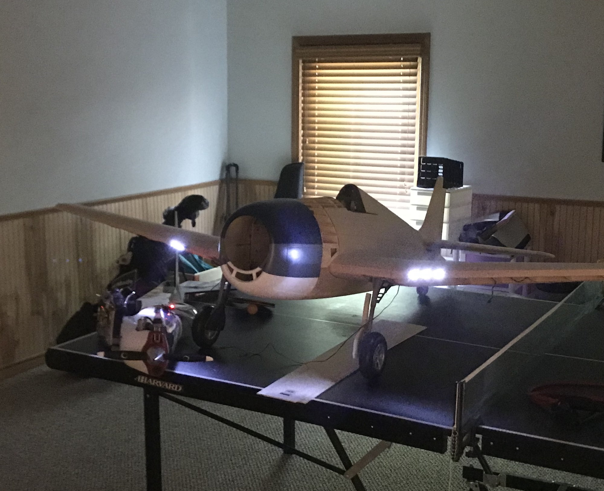
Aimed at a wall, the grouping looks good - may have been fitting by hand and using some rough measures and a homemade jig, but the results are more than good enough. Happy-happy!
The LEDs are quite bright white. Have been told that the 50-cal had a rather bright, white muzzle flash. I've only found a couple pictures of 50-cal firing, where the muzzle flash was clearly visible - at least in those pics, the flashes were bright and white.
Local hobby shop in Farmington, MI, Nankin, recently re-opened after the COVID-19 shutdown. I was able to get the aluminum tubing for the barrel mounts, there, and some 1/8" balsa sheeting to recover the fuselage front. After recovering the front fuse and getting the exhaust features reformed, oh, and finish the installation of the front belly-pan mounting blocks, I need to come to a final decision on navigation, landing and formation lights. If I go for these, I need to leave the underside of the wing open a bit longer, and probably set an appointment with Electro-Dynamics.

