


Warbird Racer Trinity-build


 02-22-2015, 01:28 PM
#502

Eric, in a nutshell the washout in theory will help make the inside of the wing stall before the tips stall. This is a sort of stability mechanism and the result is that when a stall occurs the nose drops straight ahead. Contributing factors are also wing loading, CG and airfoil loading. The first two are fairly easy as one should be building as light as the strength required will allow. For our warbirds 6.5 to 7.5 lbs is a reasonable window. If the CG is too far forward the additional elevator travel needed to compensate may create snapiness of the stall. The third one is less understood and that is as you pull hard around a turn the airfoil being used needs to maintain effiecientcy while being loaded with 25-30 G. If you have a light model with the CG placed correctly and have chosen a good airfoil you can eliminate the need for any washout. Everything is a compramise so the safest route is to add 2 degrees of washout and keep the airplane light.
 12-21-2016, 05:54 PM
#503

Thread Starter

It’s finally time to wrap-up the construction of the last part of this build. Previously, the P-39 and P-51 were completed, but the P-47 remained, awaiting completion. In the last year, life has settled enough, allowing me to find enough time to return to building my own design projects, again.
Other than building a new P-47 cowl mold and laying-up a replacement cowl, I believe main construction of the P-47 left off all the way back on page 8 of this thread. But, with building all three models simultaneously for part of the process, then focusing mainly on one for awhile, etc., I can’t remember exactly where I left off. So, if I accidentally repeat (or skip) a step, please understand.
Picking-up where I believe I left off . . .
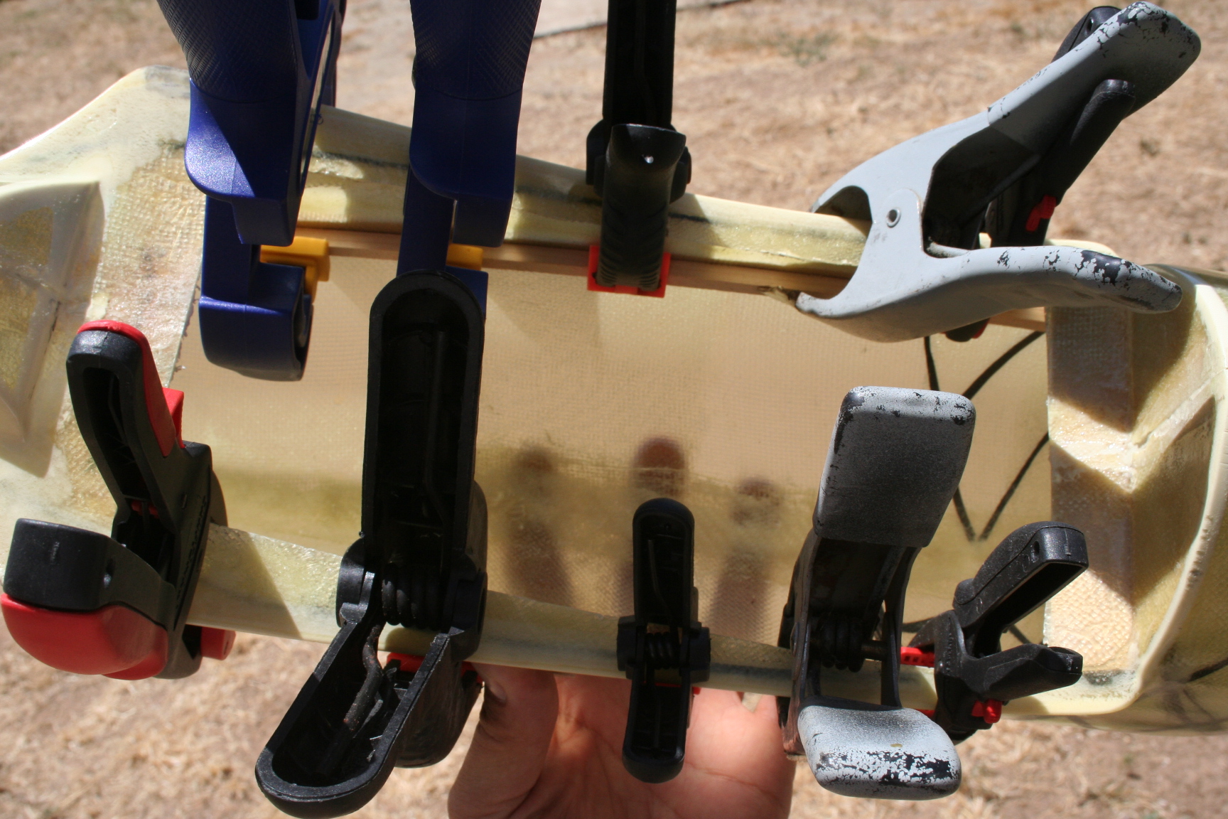
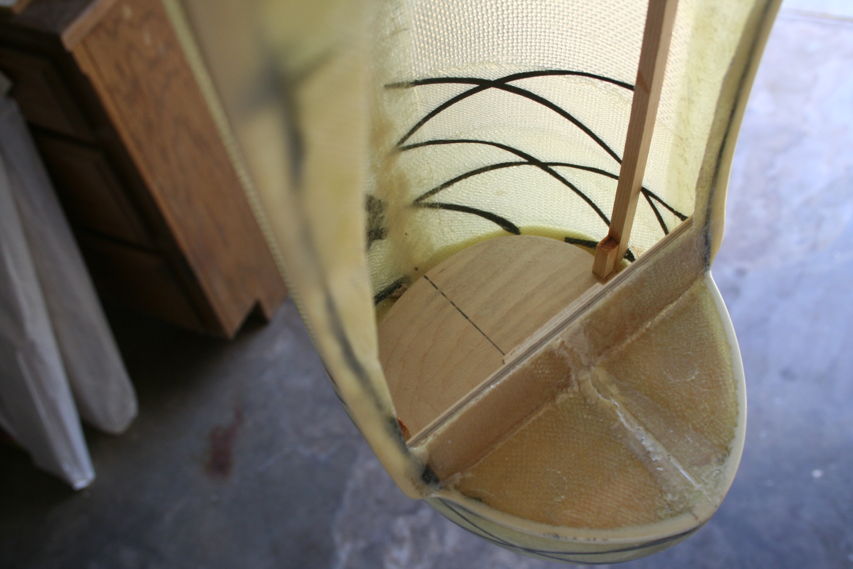
I glued the 1/8” aircraft plywood bottom former just in front of the wing saddle, in case I want to use wing dowels, instead of (or in combination with) the front wing bolts. When dry, I used OmniStick to adhere the 3/8” plywood front and rear wing mount blocks to the flat sections on the bottom of the fuse (visible on the right and left sides of the wing saddle opening in the picture below); and CA’d the clamped them, overnight. I also glued a shorter length of 1/8” as a doubler for the wing bolts to thread into.
Next, I used OmniStick to adhere the 1/4” firewall to the front of the fiberglass fuse. I stood the fuse on its nose, so the firewall laid flat against the floor of my shop, and placed one of my 5-pound scuba weight bags inside the fuse to weight it down, flat, until the glue dried.
Last in this step, I used OmniStick, again, to adhere the 1/4 x 1/4” spruce sticks that run the length of the fuse. Because the fuse is tapered at each end, clamping the spruce at the widest part of the fuse (from within the wing saddle opening) pulls it tight along its entire length.
Other than building a new P-47 cowl mold and laying-up a replacement cowl, I believe main construction of the P-47 left off all the way back on page 8 of this thread. But, with building all three models simultaneously for part of the process, then focusing mainly on one for awhile, etc., I can’t remember exactly where I left off. So, if I accidentally repeat (or skip) a step, please understand.
Picking-up where I believe I left off . . .
I glued the 1/8” aircraft plywood bottom former just in front of the wing saddle, in case I want to use wing dowels, instead of (or in combination with) the front wing bolts. When dry, I used OmniStick to adhere the 3/8” plywood front and rear wing mount blocks to the flat sections on the bottom of the fuse (visible on the right and left sides of the wing saddle opening in the picture below); and CA’d the clamped them, overnight. I also glued a shorter length of 1/8” as a doubler for the wing bolts to thread into.
Next, I used OmniStick to adhere the 1/4” firewall to the front of the fiberglass fuse. I stood the fuse on its nose, so the firewall laid flat against the floor of my shop, and placed one of my 5-pound scuba weight bags inside the fuse to weight it down, flat, until the glue dried.
Last in this step, I used OmniStick, again, to adhere the 1/4 x 1/4” spruce sticks that run the length of the fuse. Because the fuse is tapered at each end, clamping the spruce at the widest part of the fuse (from within the wing saddle opening) pulls it tight along its entire length.
12-21-2016, 06:00 PM
#504
Thread Starter
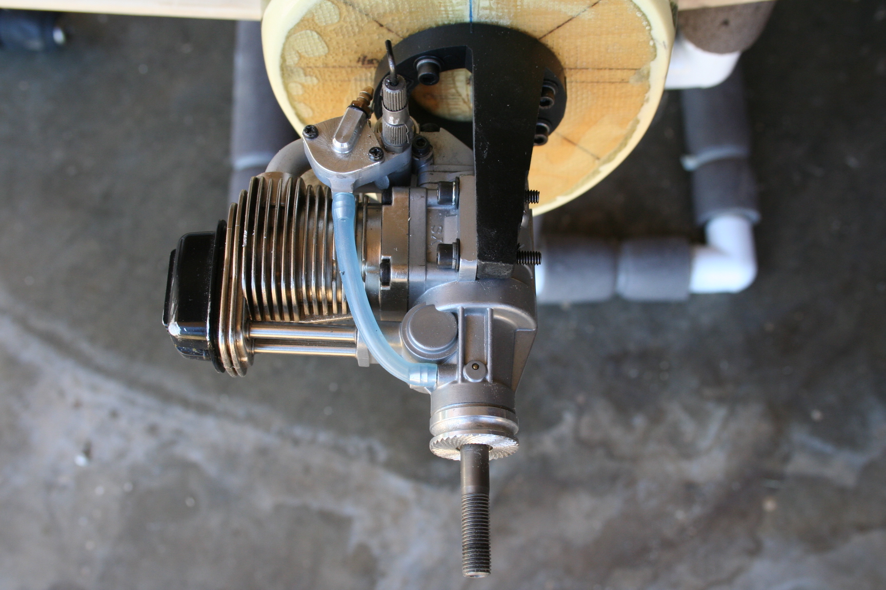
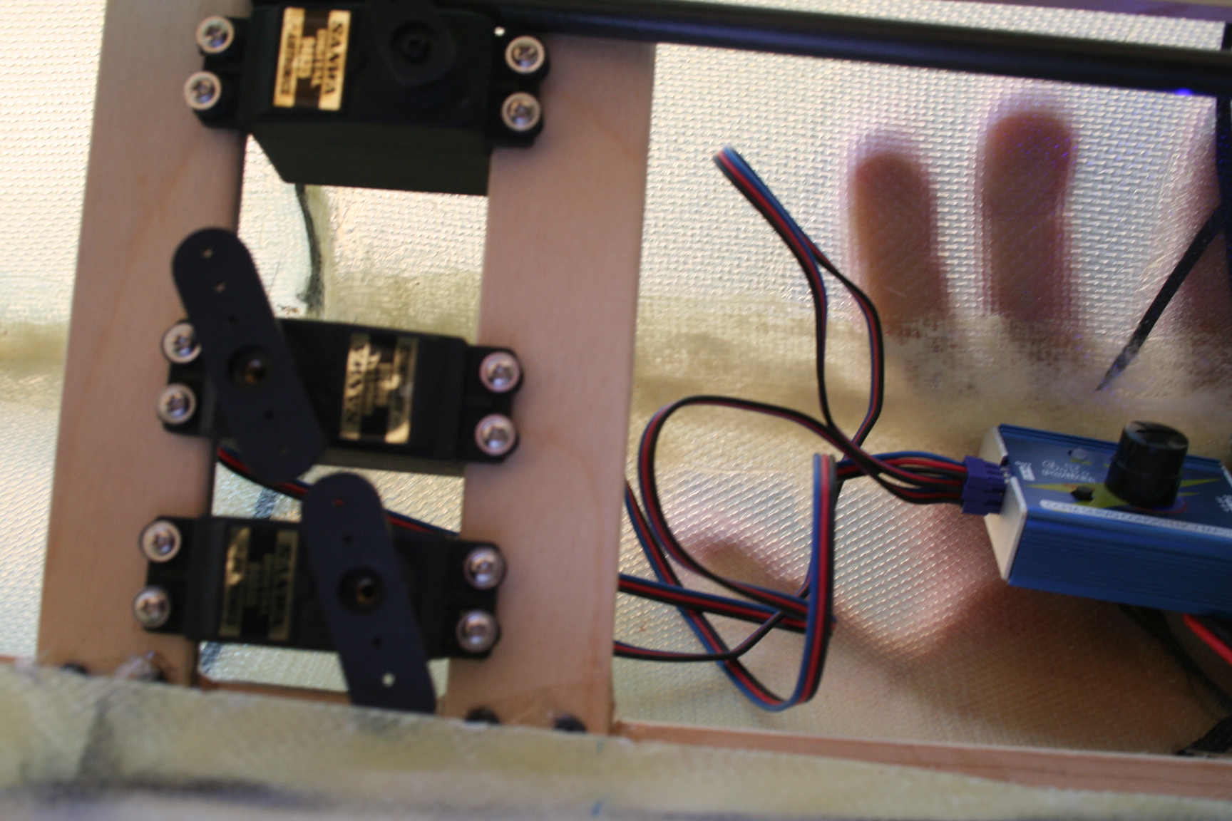
Two pieces of 3/8� ply were cut and sanded to the width of the fuse at the rear of the wing saddle opening. They were installed to the width of the servos used, and were both glued and screwed to the 1/4" square spruce sticks that run the length of the fuse.
The engine mount and YS .70 were installed. Servos were installed and the throttle pushrod was installed. I chose to enclose this pushrod in a piece of scrap 1/4" hollow carbon fiber rod so that any friction with foam that later insulates the tank, battery, and receiver will be eliminated.
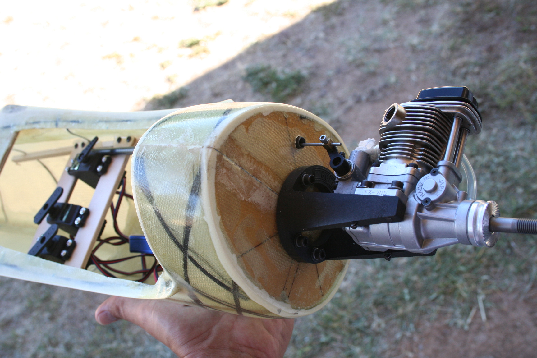
The engine mount and YS .70 were installed. Servos were installed and the throttle pushrod was installed. I chose to enclose this pushrod in a piece of scrap 1/4" hollow carbon fiber rod so that any friction with foam that later insulates the tank, battery, and receiver will be eliminated.
Last edited by Iron Dog; 12-21-2016 at 06:27 PM.
12-21-2016, 06:54 PM
#505
Thread Starter
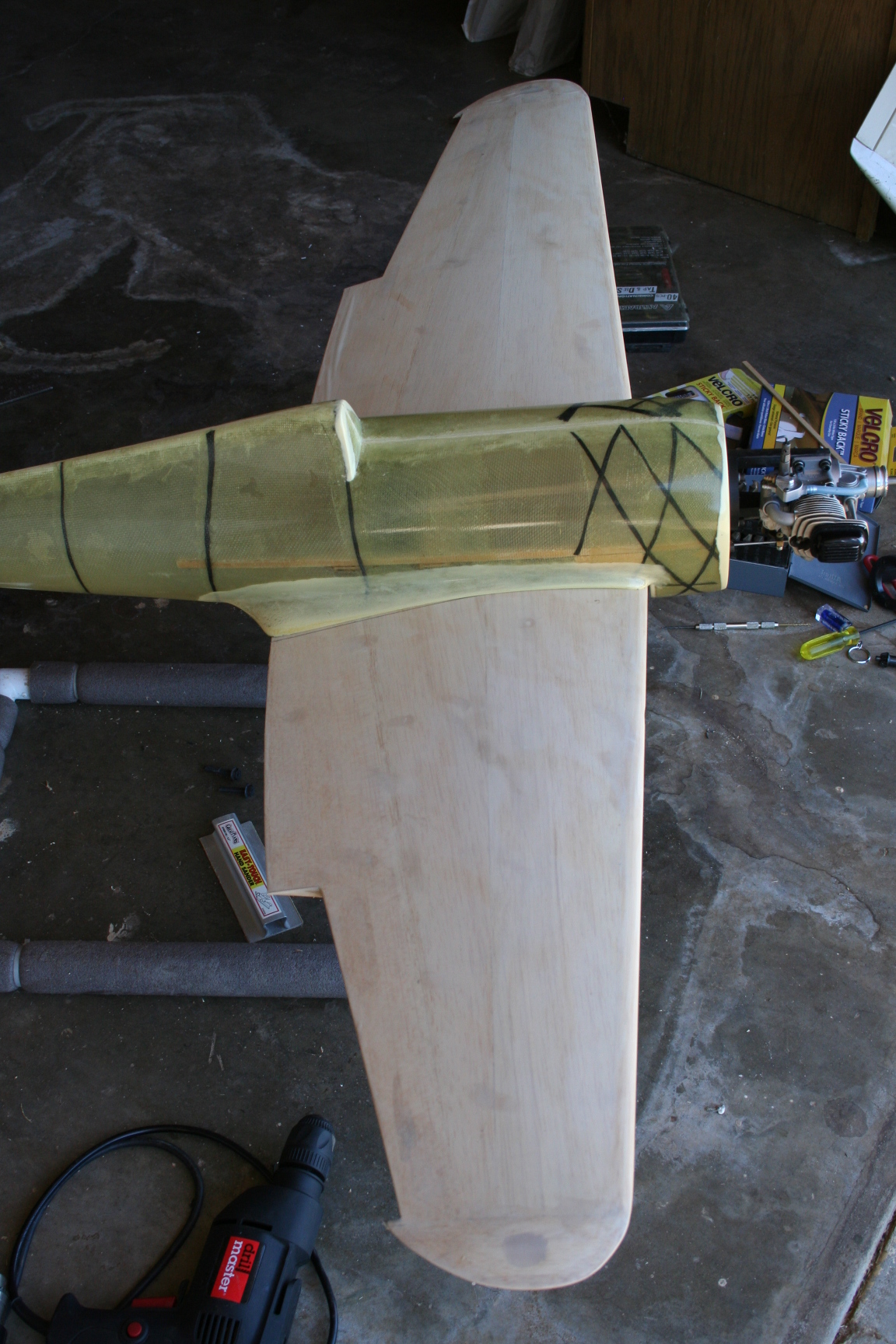
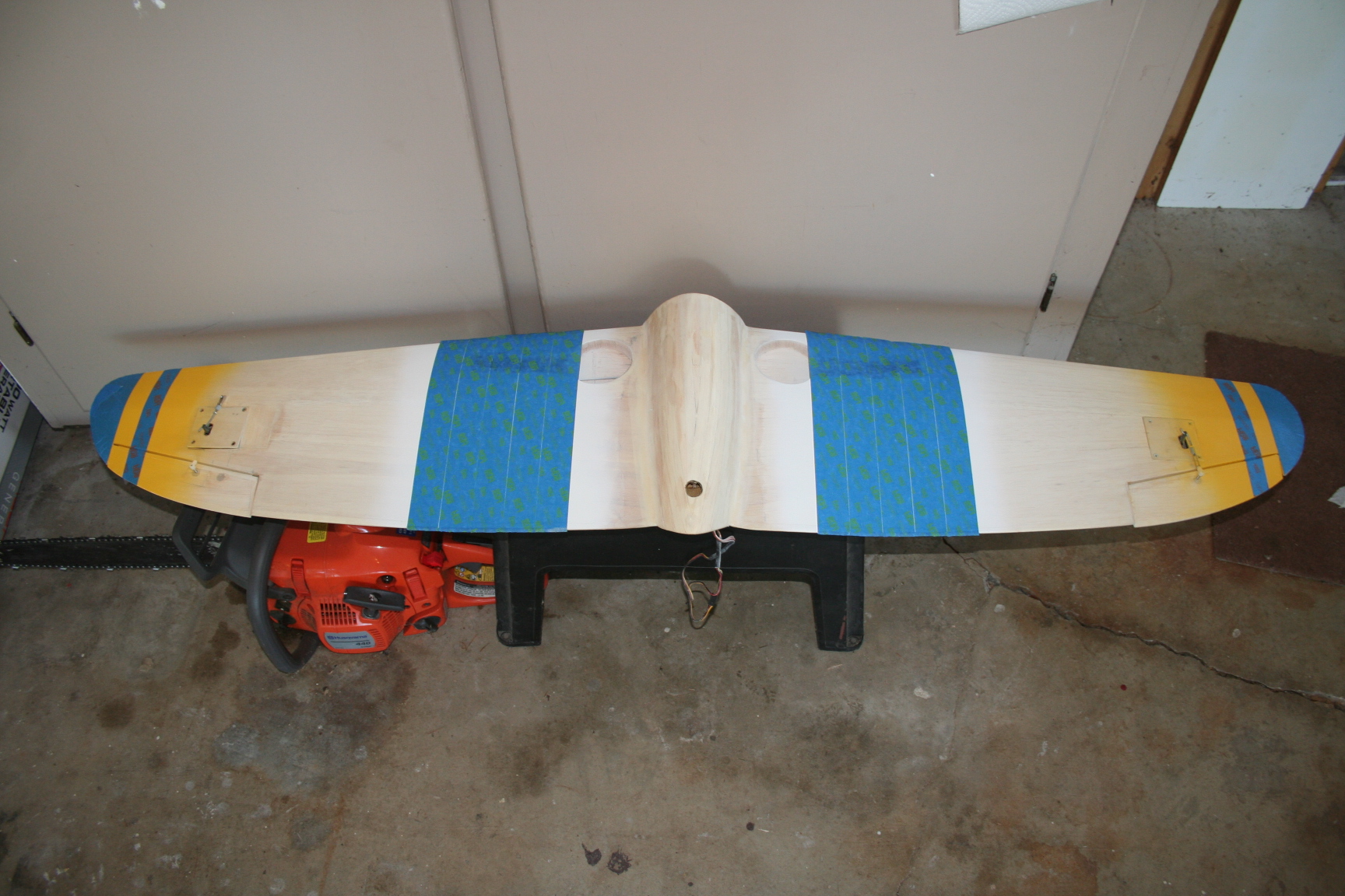
The wing was set on the fuse and carefully aligned with the rear of the fuse. Bolt holes were drilled through the wing, and through the wing mount blocks in the fuse.
12-21-2016, 06:55 PM
#506
Thread Starter
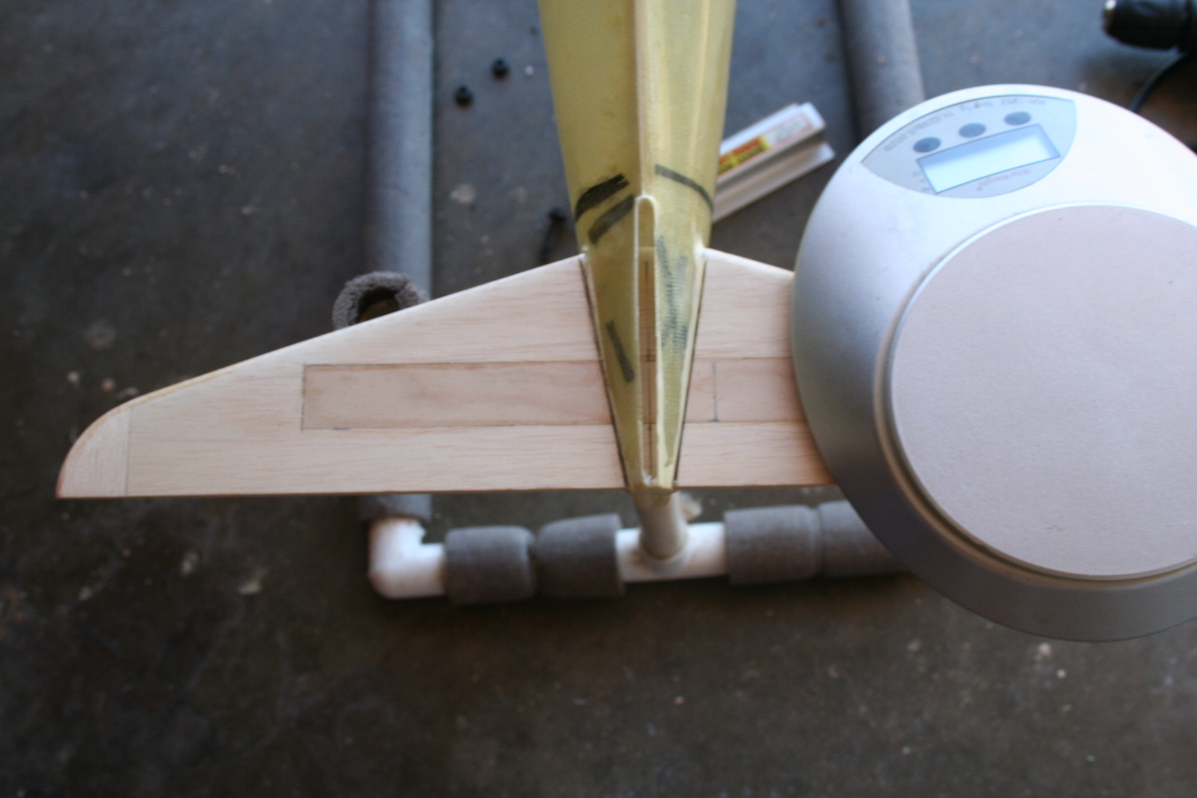
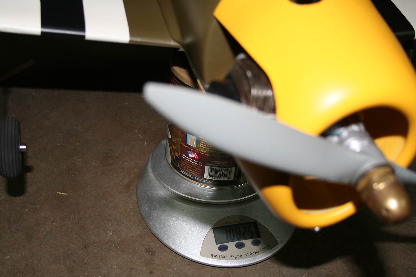
The horizontal stab was aligned with the wing and then glued with OmniStick. I had to use my digital scale to add weight to the right side so that the stab would be parallel to the wing.
12-21-2016, 06:59 PM
#507
Thread Starter
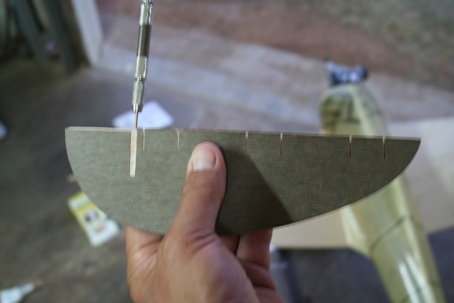
I used my Formica cutting template to guide the alignment of my hand-drill, when drilling the hole into the 1/8” balsa pieces that were glued around the slotted 1/64[SUP]th[/SUP] ply center section. The slots in this rudder assembly are for the steering-arm of the music wire tail-wheel assembly.
12-21-2016, 07:02 PM
#508
Thread Starter
Returning to the wing, it is time to install the composite-molded belly pan.
To do so, I cut 1/8” balsa formers to the contour of the front and rear of the fuselage – each braced with a plywood triangle. I used a 1/16” piece of sheeting as a spacer when gluing the formers into place, parallel to the fuse.
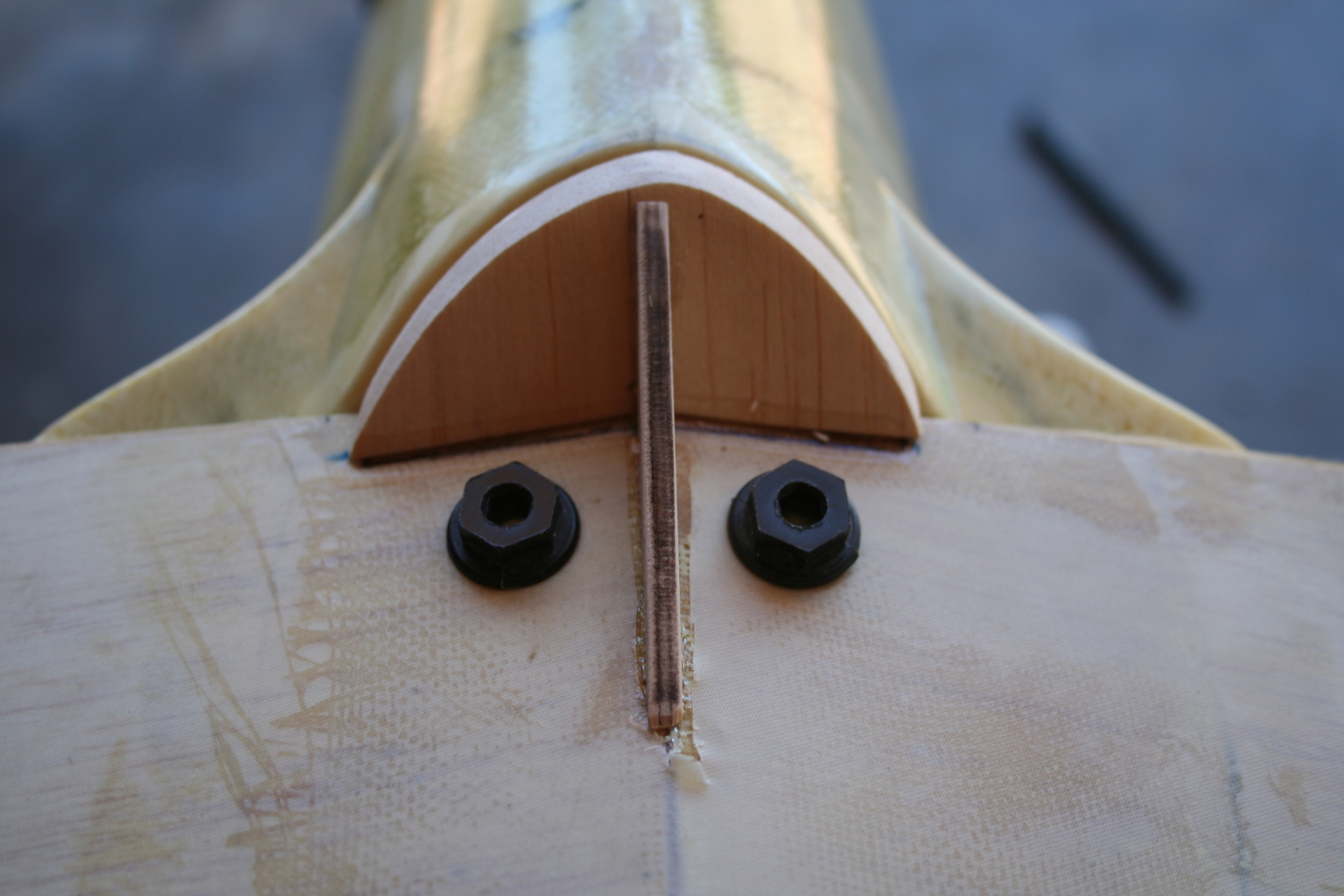
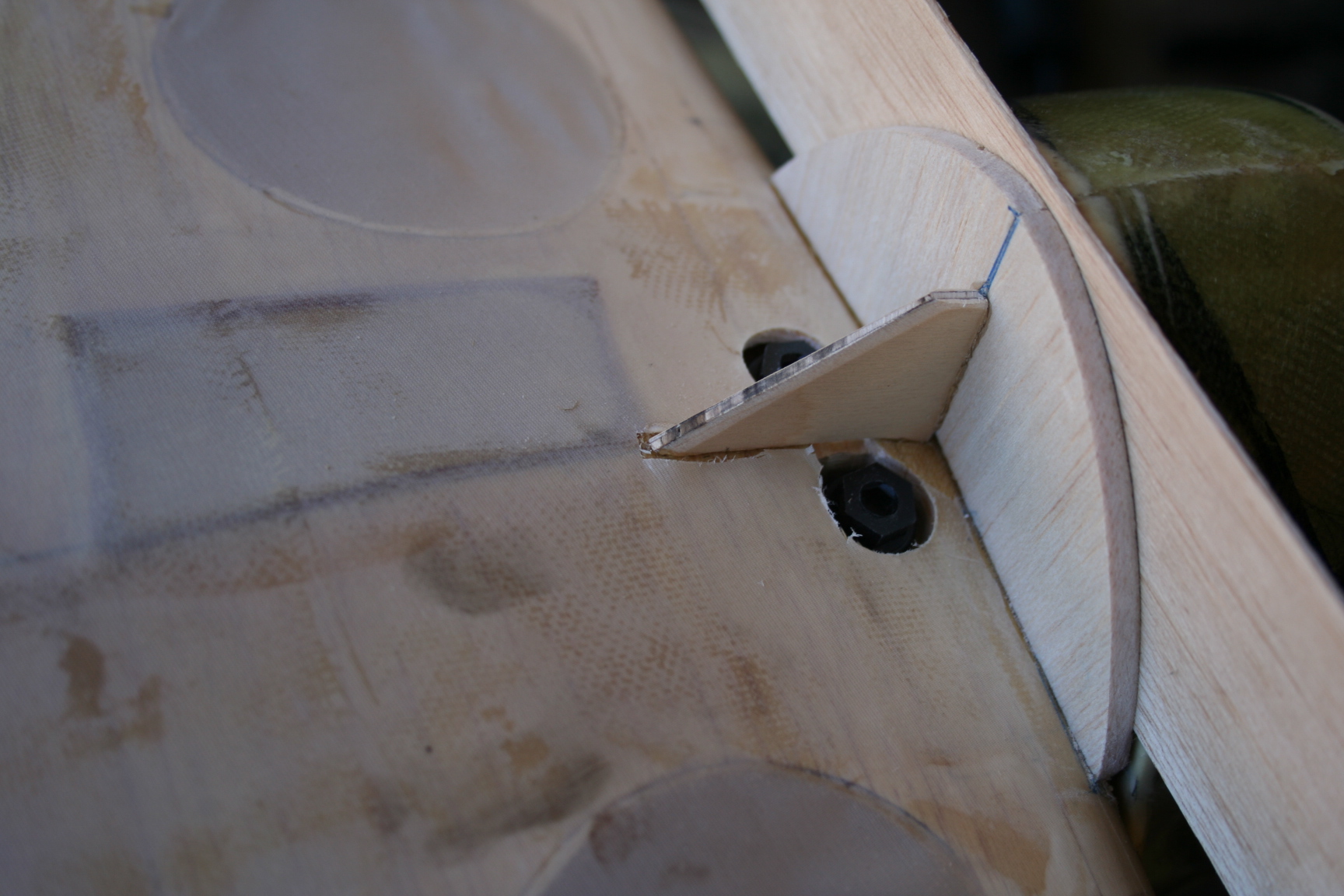
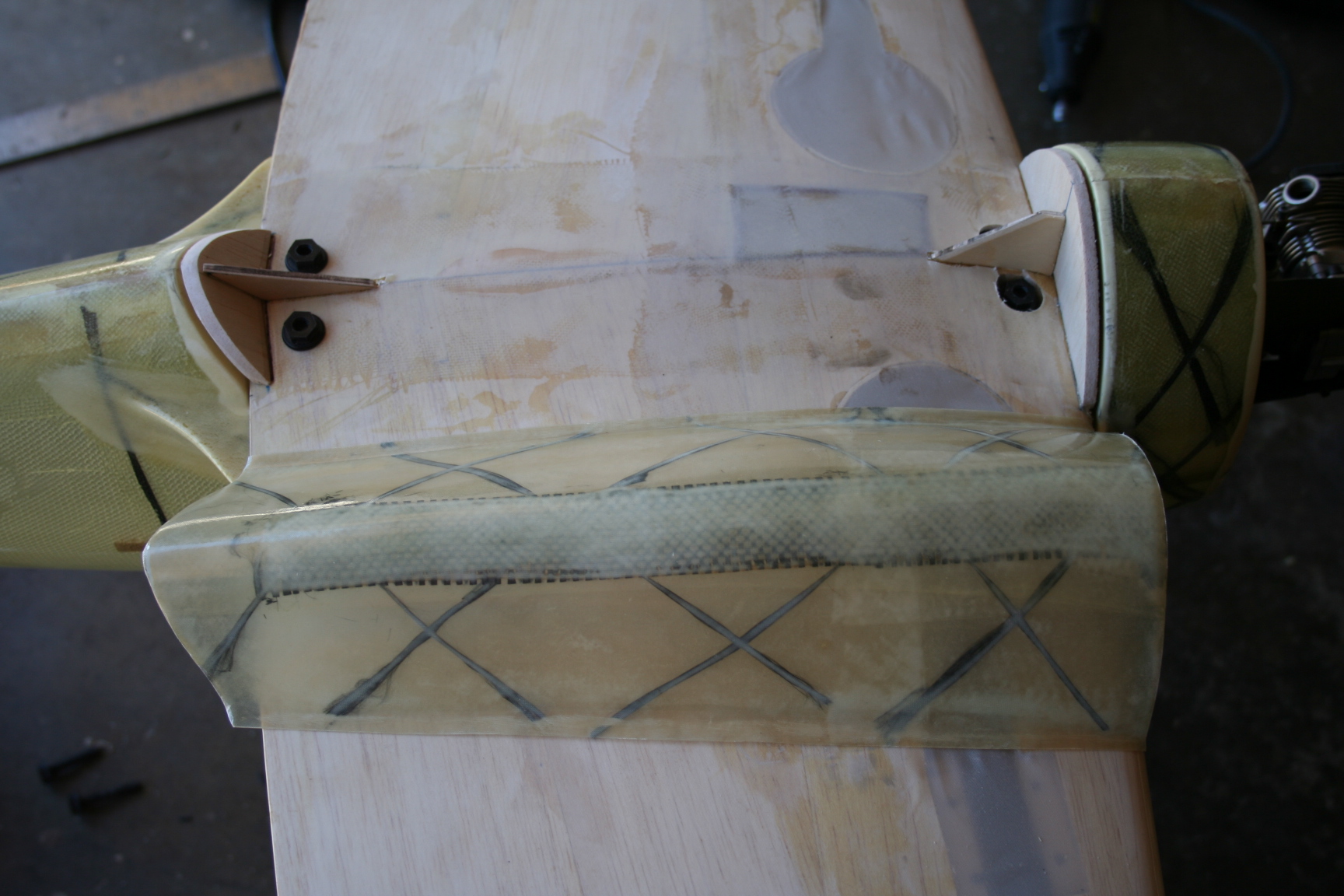
To do so, I cut 1/8” balsa formers to the contour of the front and rear of the fuselage – each braced with a plywood triangle. I used a 1/16” piece of sheeting as a spacer when gluing the formers into place, parallel to the fuse.
12-21-2016, 07:05 PM
#509
Thread Starter
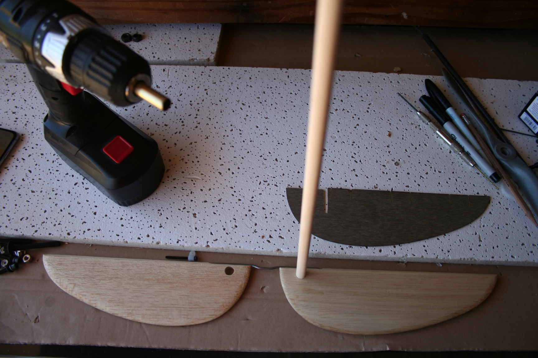
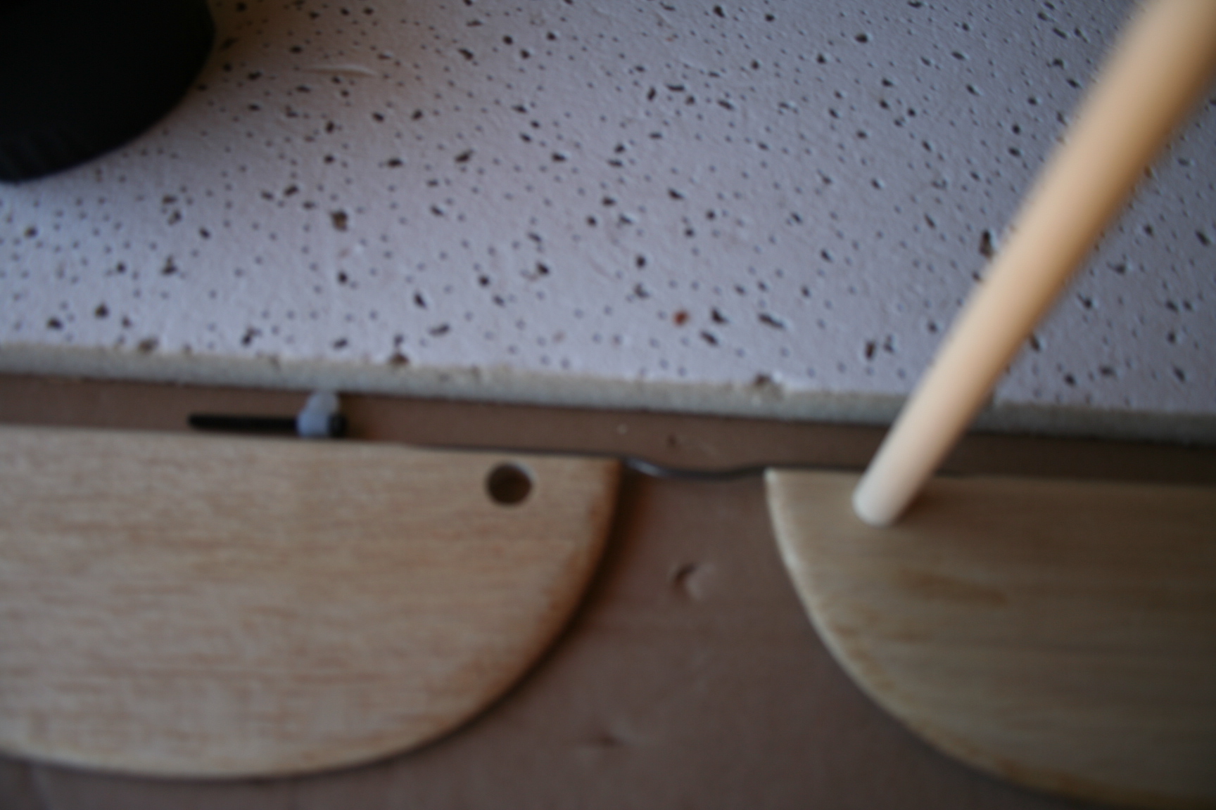
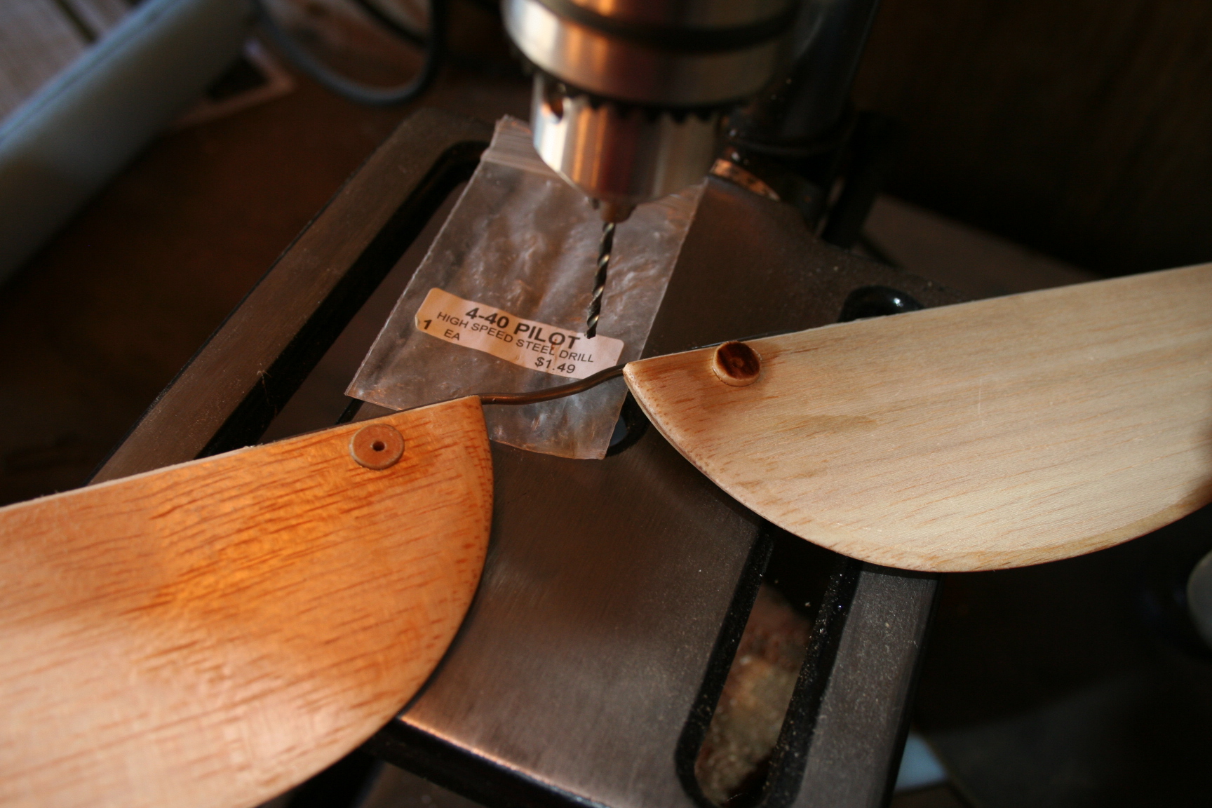
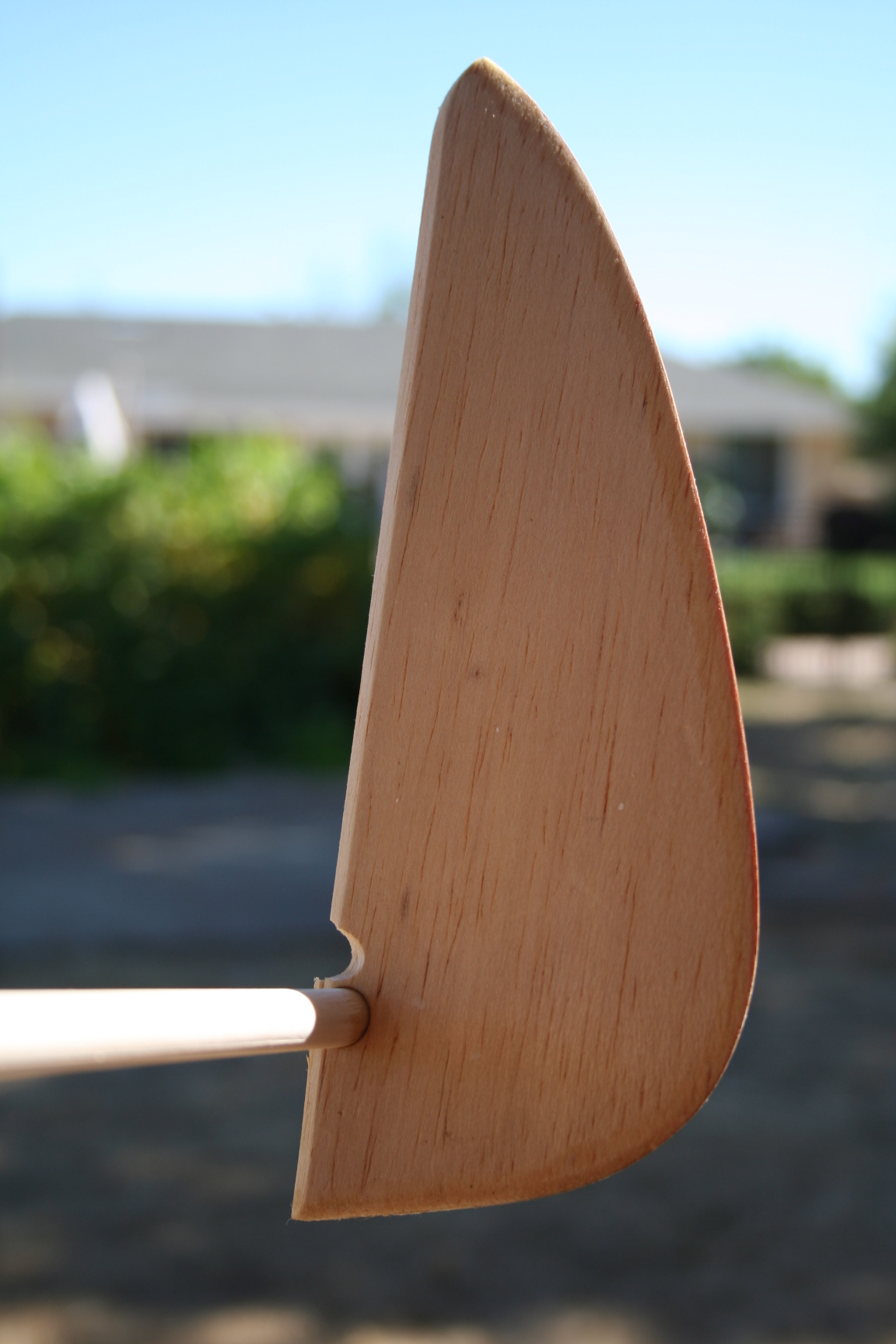
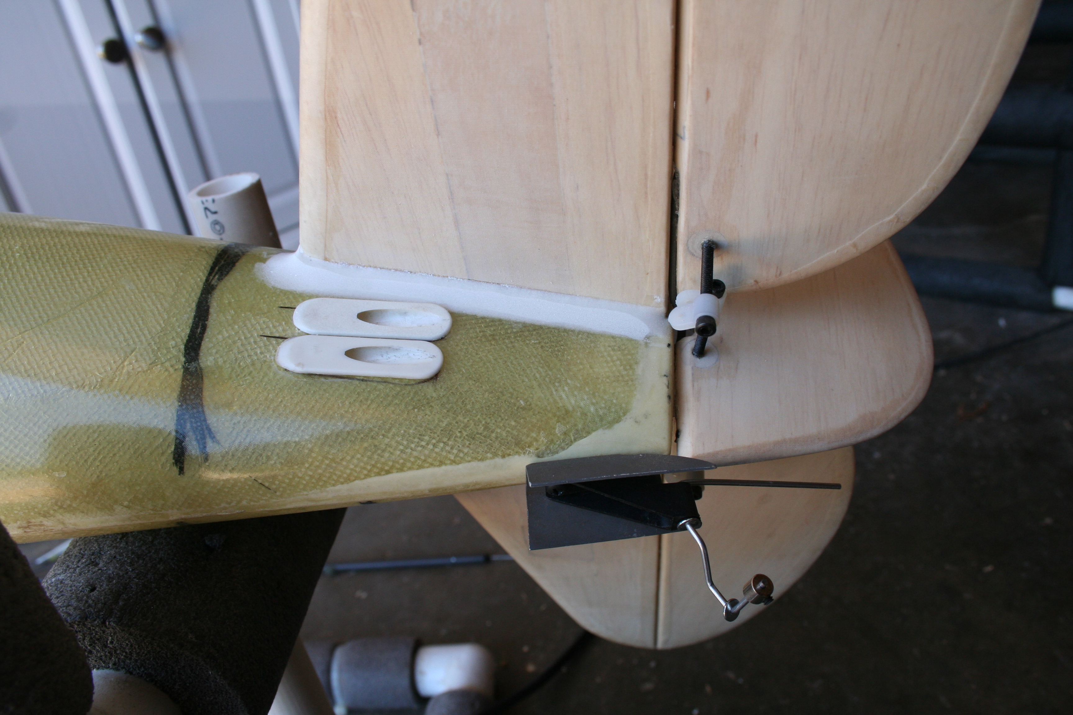
Using a sharpened piece of brass tubing inserted into a cordless drill, holes were cut through both elevator halves and the rudder, matching the diameter of the hardwood dowel that was inserted and glued in-place. I use as large a diameter dowel as I can find at the time needed (usually 3/8 or larger). The dowel is cut and sanded flush with each control surface. An ice-pick was used to make an indent in the center of the dowel, prior to the 4-40 pilot hole being drilled and tapped. A 1 1/4” 4-40 bolt and Dubro nylon horn were epoxied into the dowel, forming each control horn.
12-21-2016, 07:09 PM
#510
Thread Starter
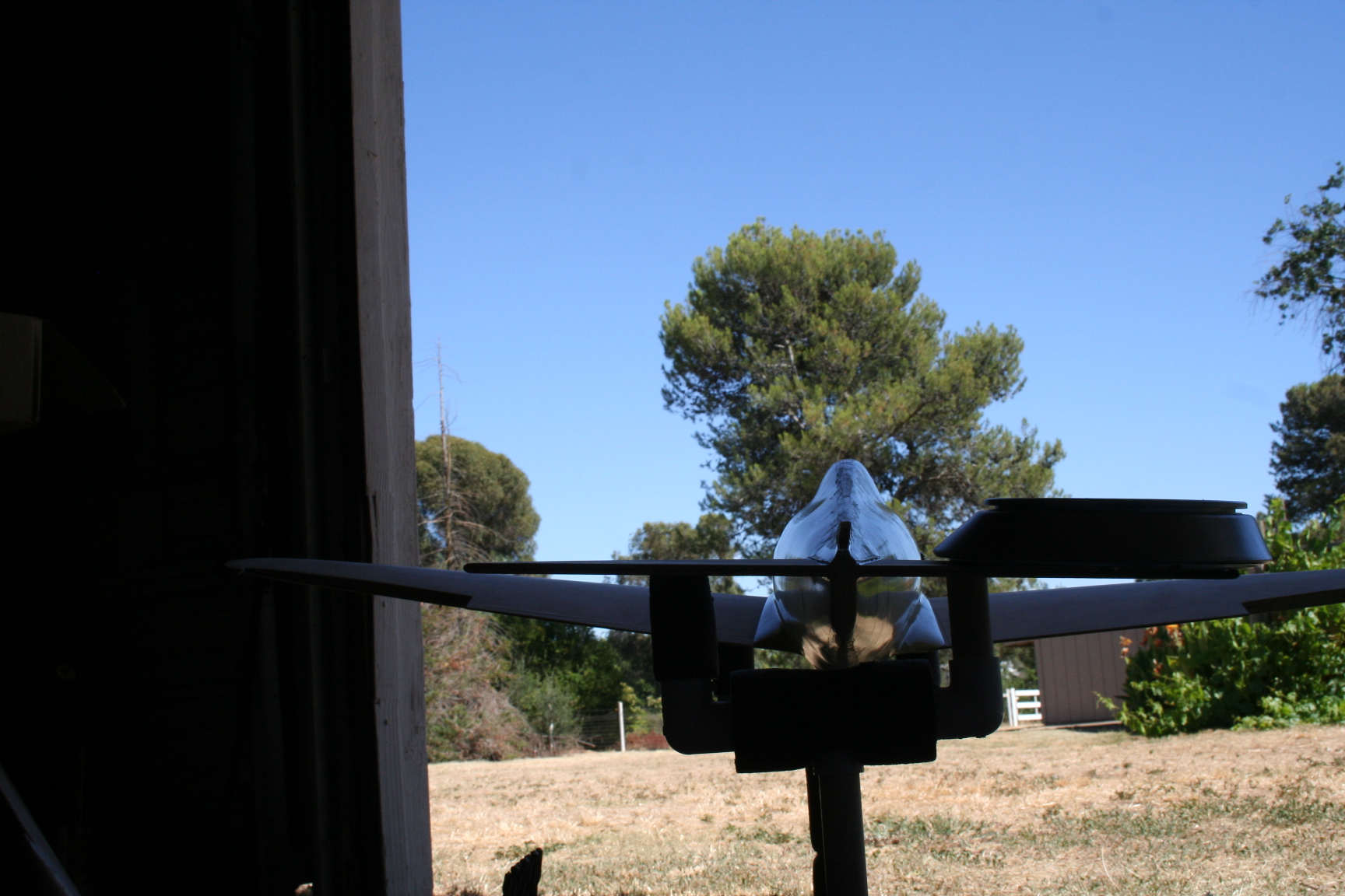
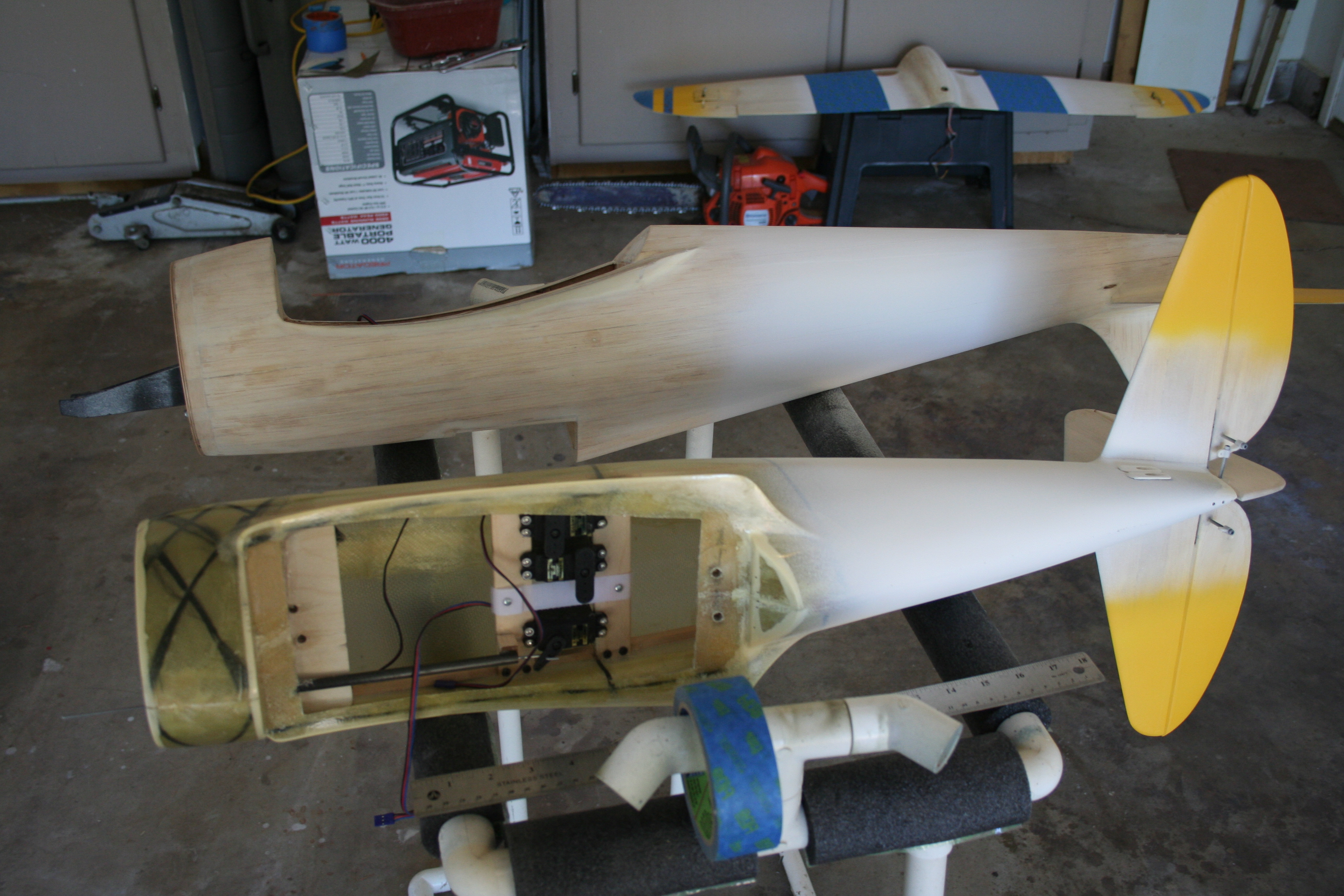
With the glue holding the stab in-place now cured, I inserted the vertical fin. The bottom of the fin was epoxied to the stab, and the sides were glued to the fiberglass fuse with OmniStick.
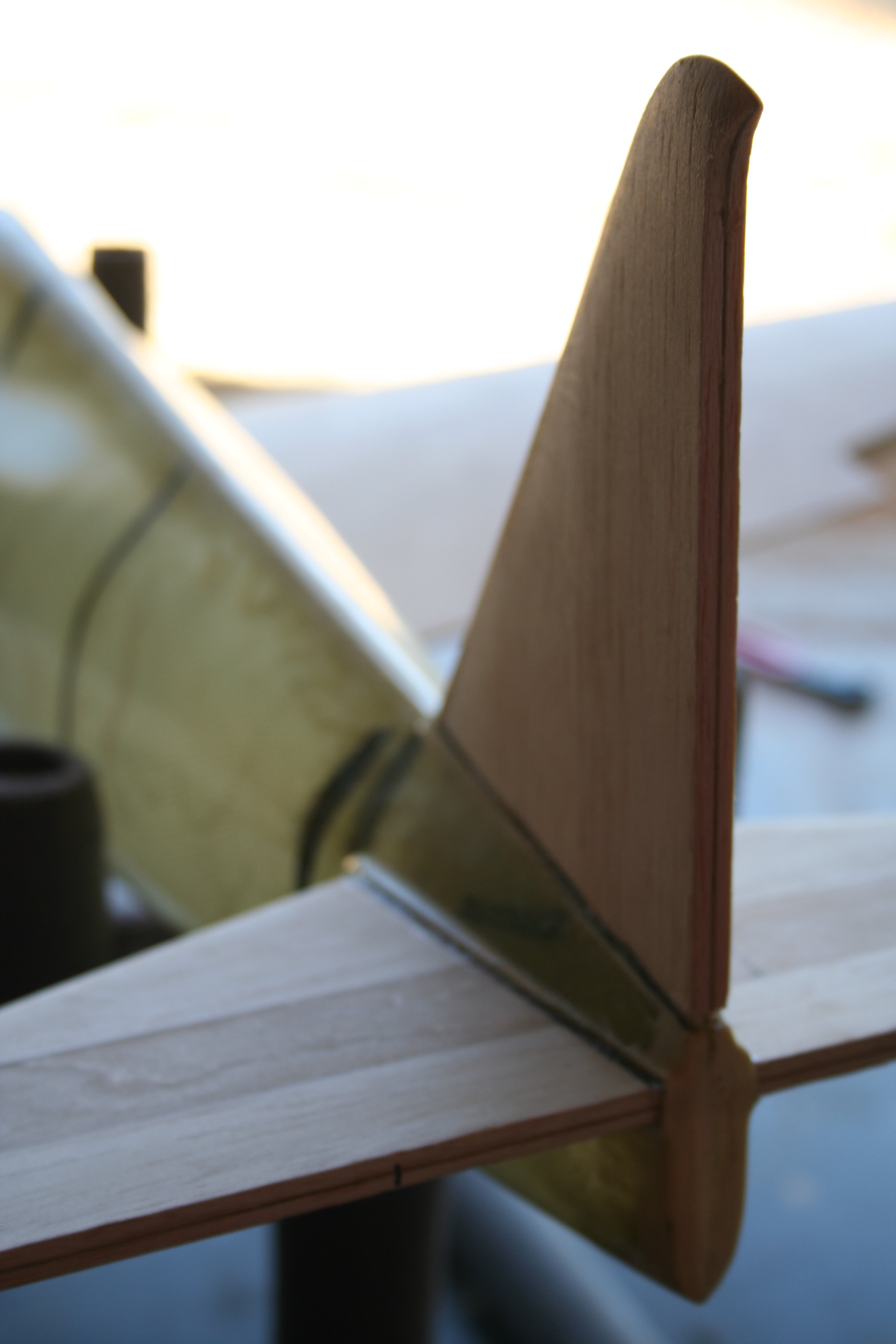
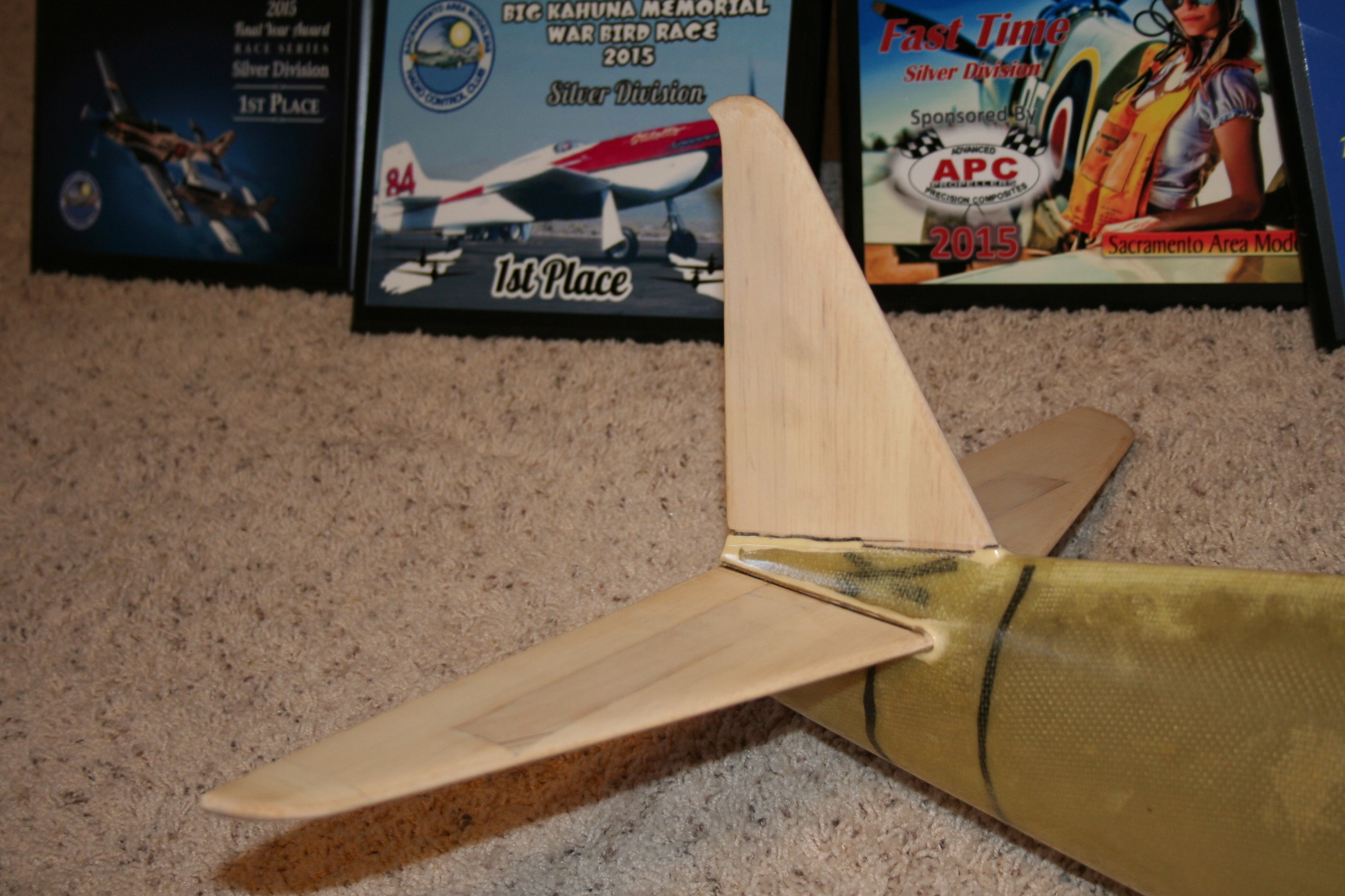
Here is the P-47 fuse next to my repaired Trinity-build P-39.
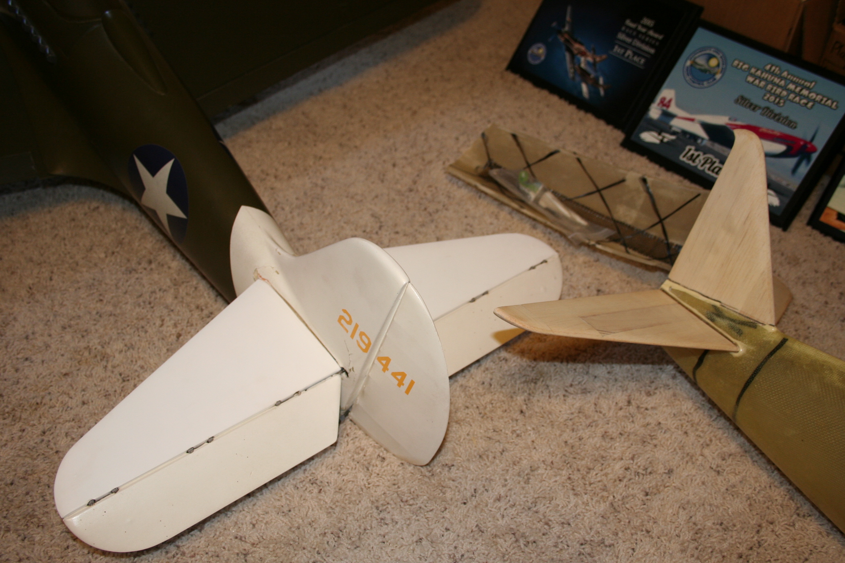
Here is the P-47 fuse next to my repaired Trinity-build P-39.
12-21-2016, 07:26 PM
#511
Thread Starter
The next day, I covered the exposed stab and vertical fin with white Solartex – taking the Solartex right up to the edge of the fuse. I taped-off these surfaces just outside of the edge of the covering material, and applied resin mixed with microballoons. After the microballoons start to gel, the tape is peeled-back. I then used narrow-diameter sanding sleeves to sand the contours of the fillets.
01-14-2017, 06:13 PM
#512
Thread Starter
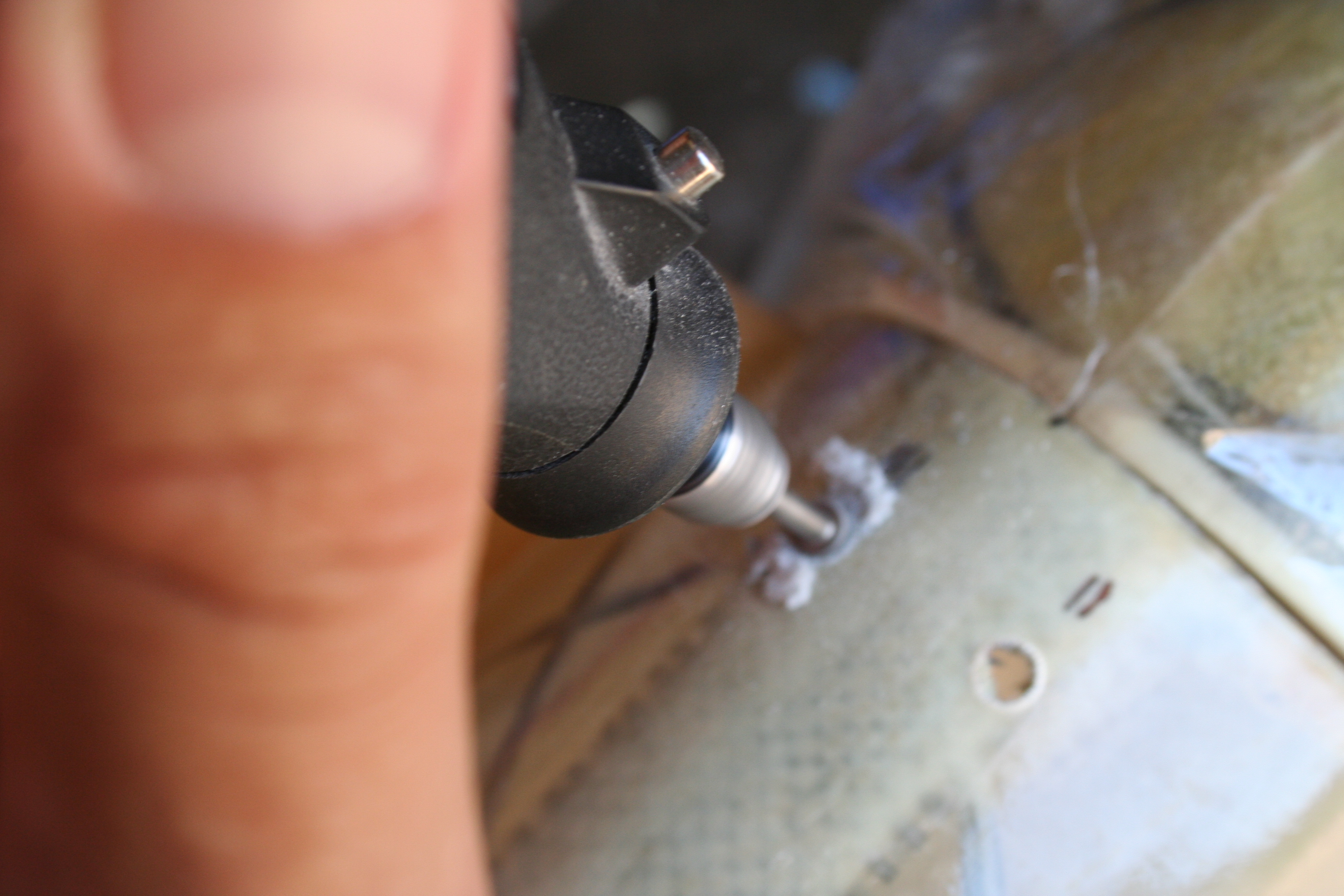
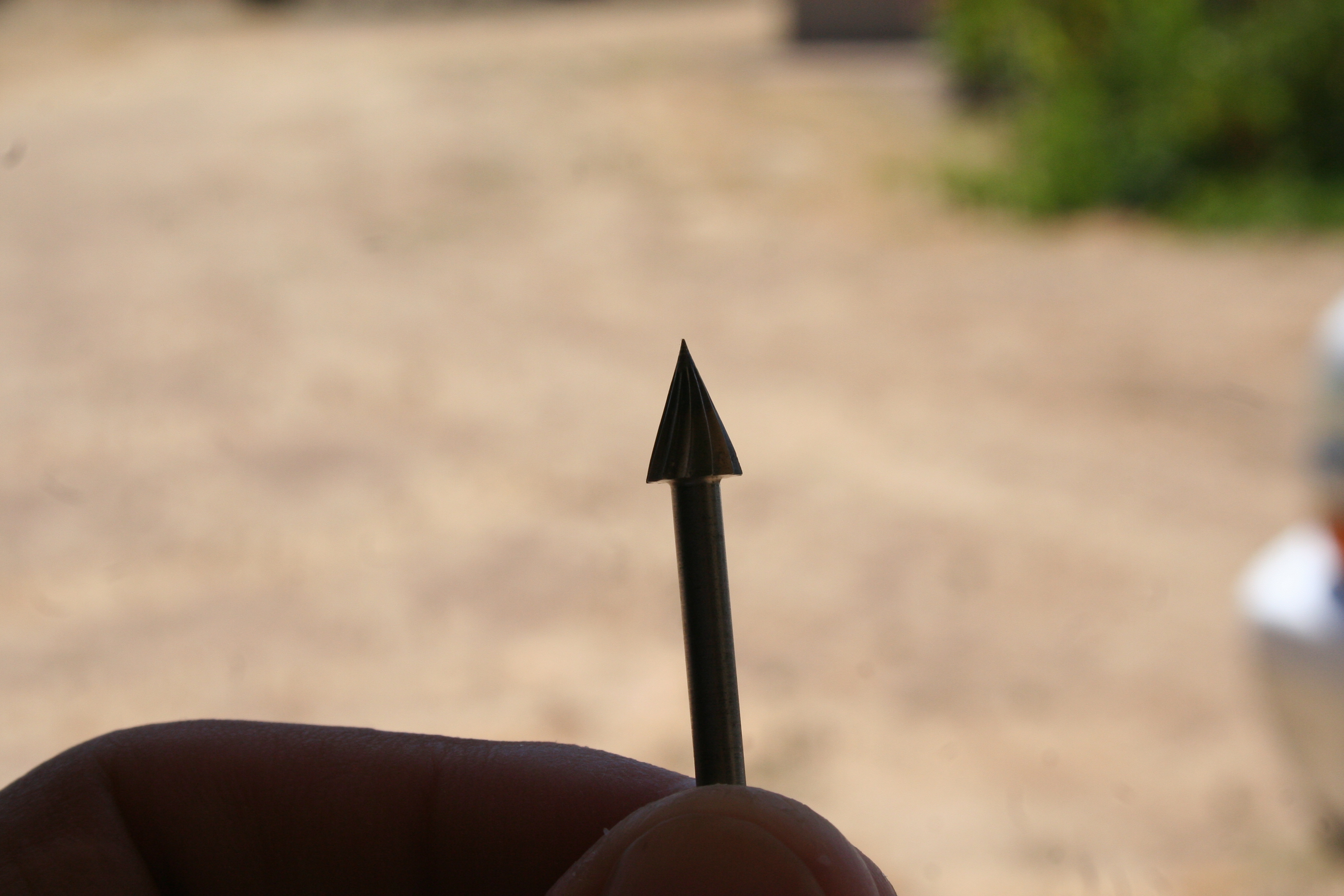
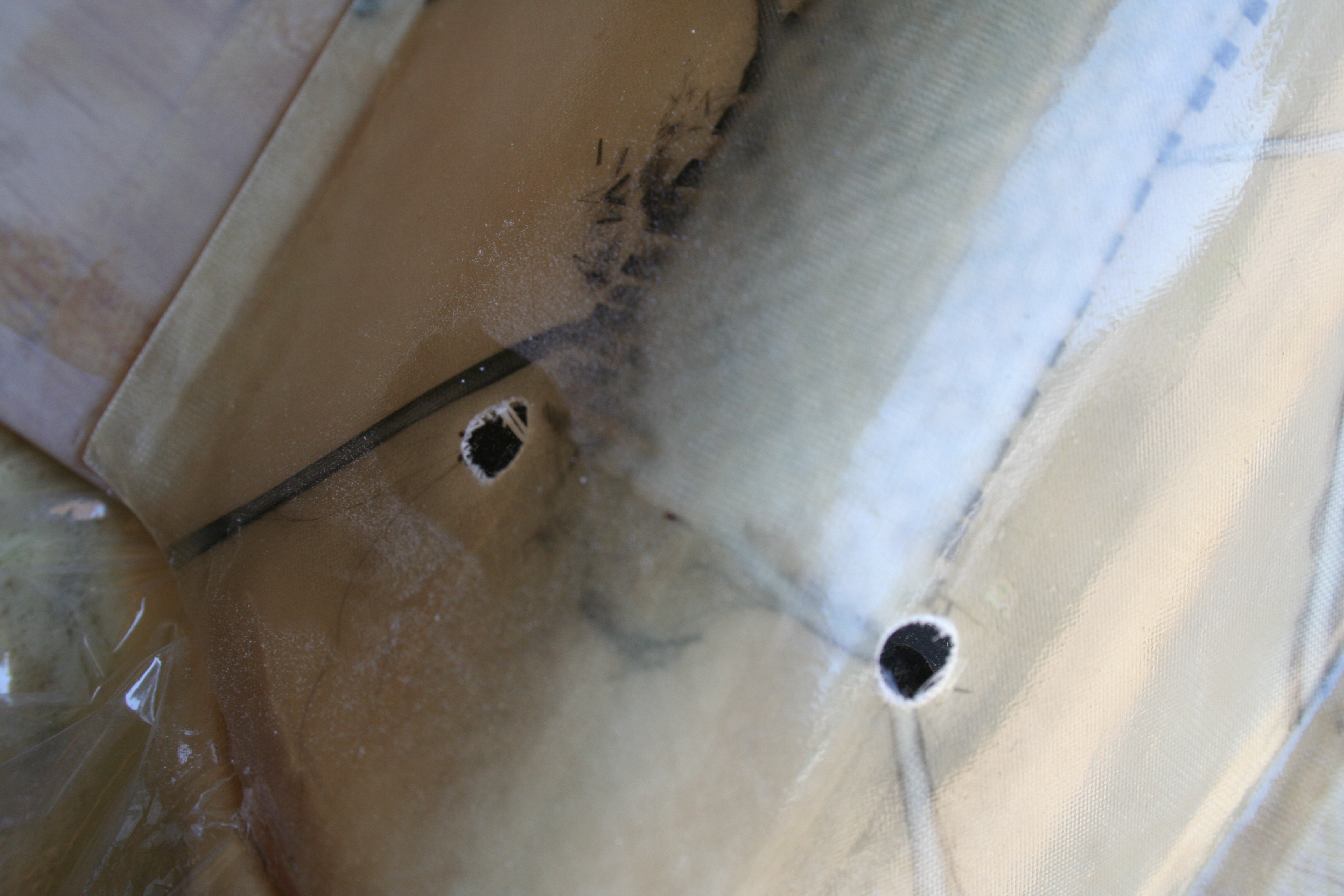
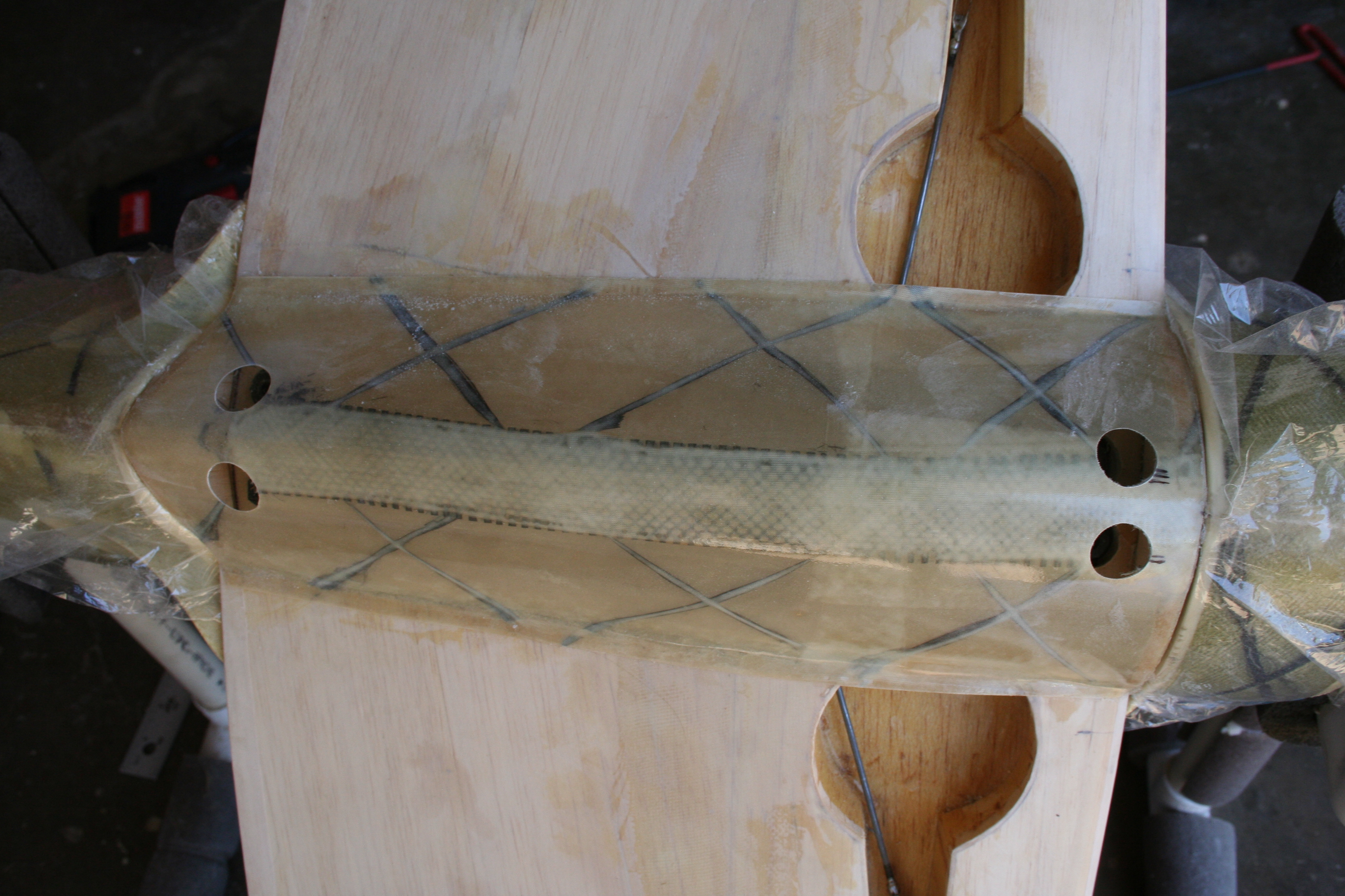
Now that the bellypan's glue is dry, I return to working on it. Small diameter holes are drilled over the position of the wing bolts, using a sharp conical shaped Dremel cutting bit. The holes are expanded and more accurately centered directly over the bold heads.
01-14-2017, 06:35 PM
#513
Thread Starter
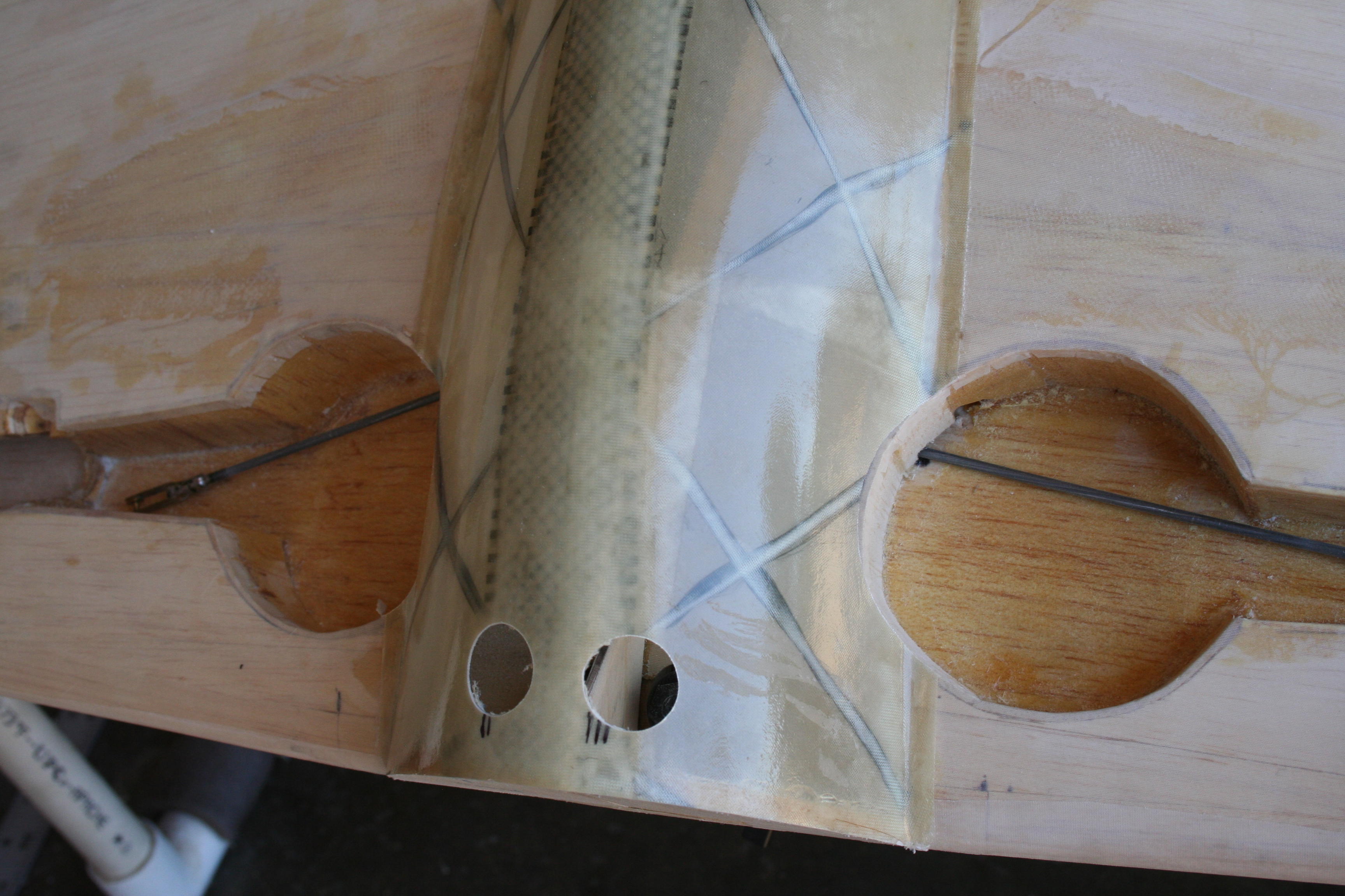
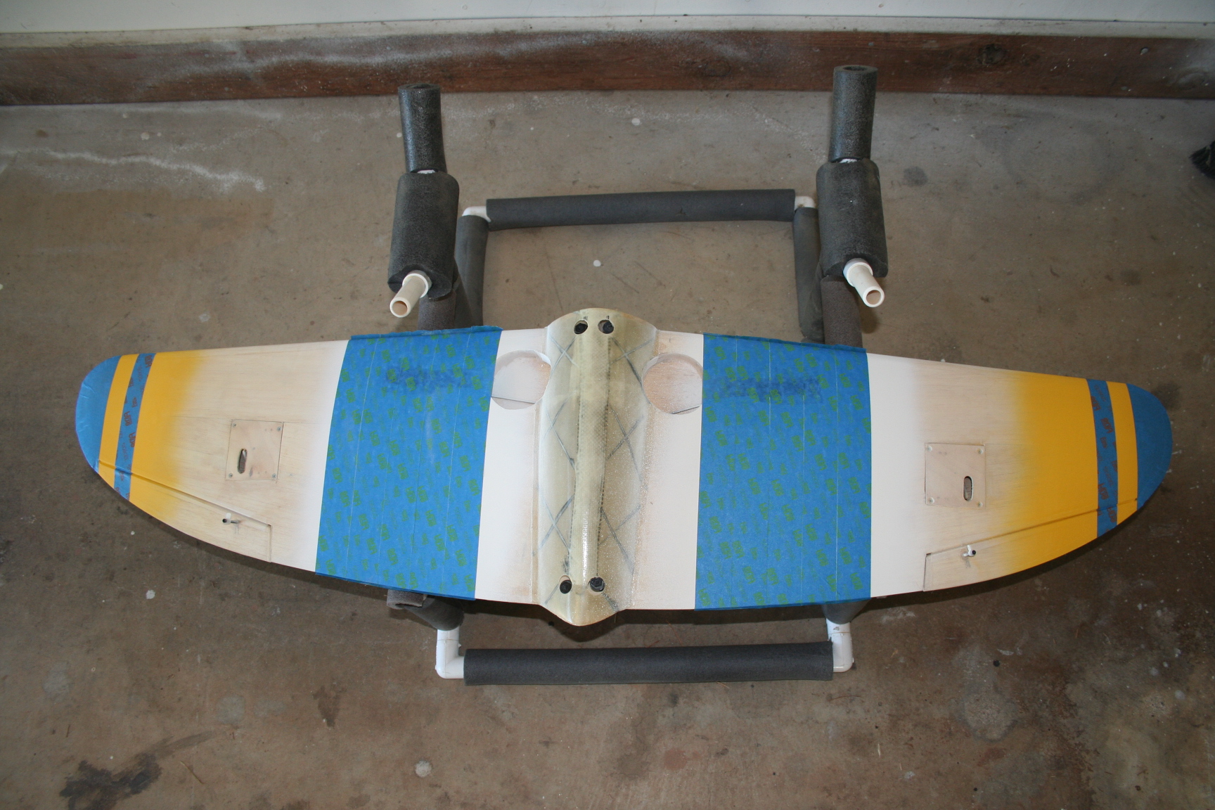
I am extremely grateful for the time my father-in-law invested in helping me with this build. More specifically, he was kind enough to build the wing for me, being I was having trouble finding time to build, myself. (Very evident by how long this build ended up taking.) I told him I wanted to use larger diameter and more scale wheels than he usually uses. Unfortunately, this made the wheel wells a little larger of a diameter, and until I installed the belly pan, neither of us realized that the belly pan would now cut-into each wheel well.
It's another "make it work" moment!
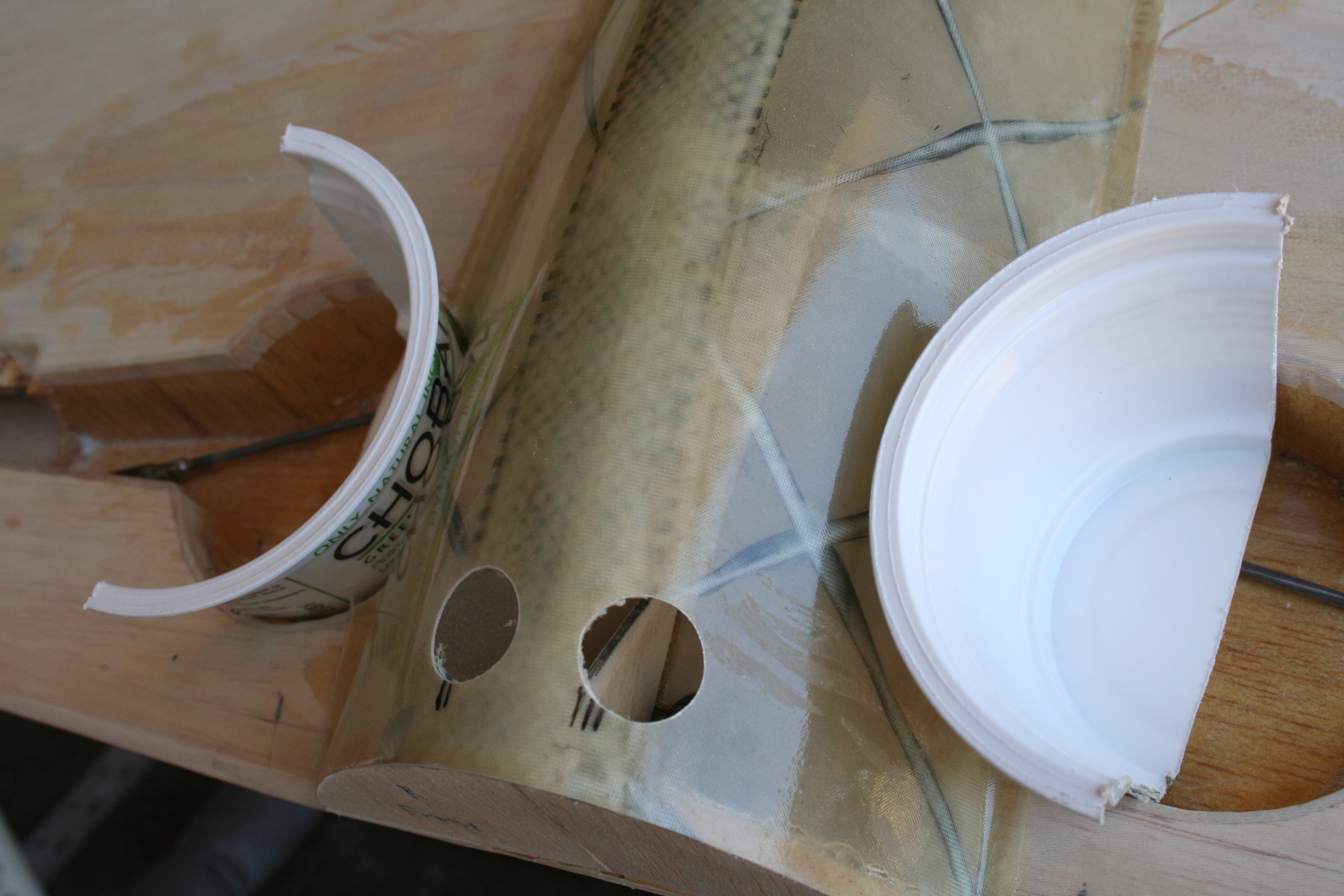
I see little choice but to cut into the composite belly pan, sanding it to the contour of the inside of both wheel wells. Unfortunately, the more the belly pan's slope, as I sand further into it towards the middle of the well, the larger the gap between the bottom of the wing, and the edge of the belly pan. Now it is necessary to find something to fill this gap.
I decide to use a the sides of a Chobani yogurt container, as its diameter and contour matches the curvature of the existing wheel well almost precisely.
It's another "make it work" moment!
I see little choice but to cut into the composite belly pan, sanding it to the contour of the inside of both wheel wells. Unfortunately, the more the belly pan's slope, as I sand further into it towards the middle of the well, the larger the gap between the bottom of the wing, and the edge of the belly pan. Now it is necessary to find something to fill this gap.
I decide to use a the sides of a Chobani yogurt container, as its diameter and contour matches the curvature of the existing wheel well almost precisely.
01-14-2017, 06:51 PM
#514
Thread Starter
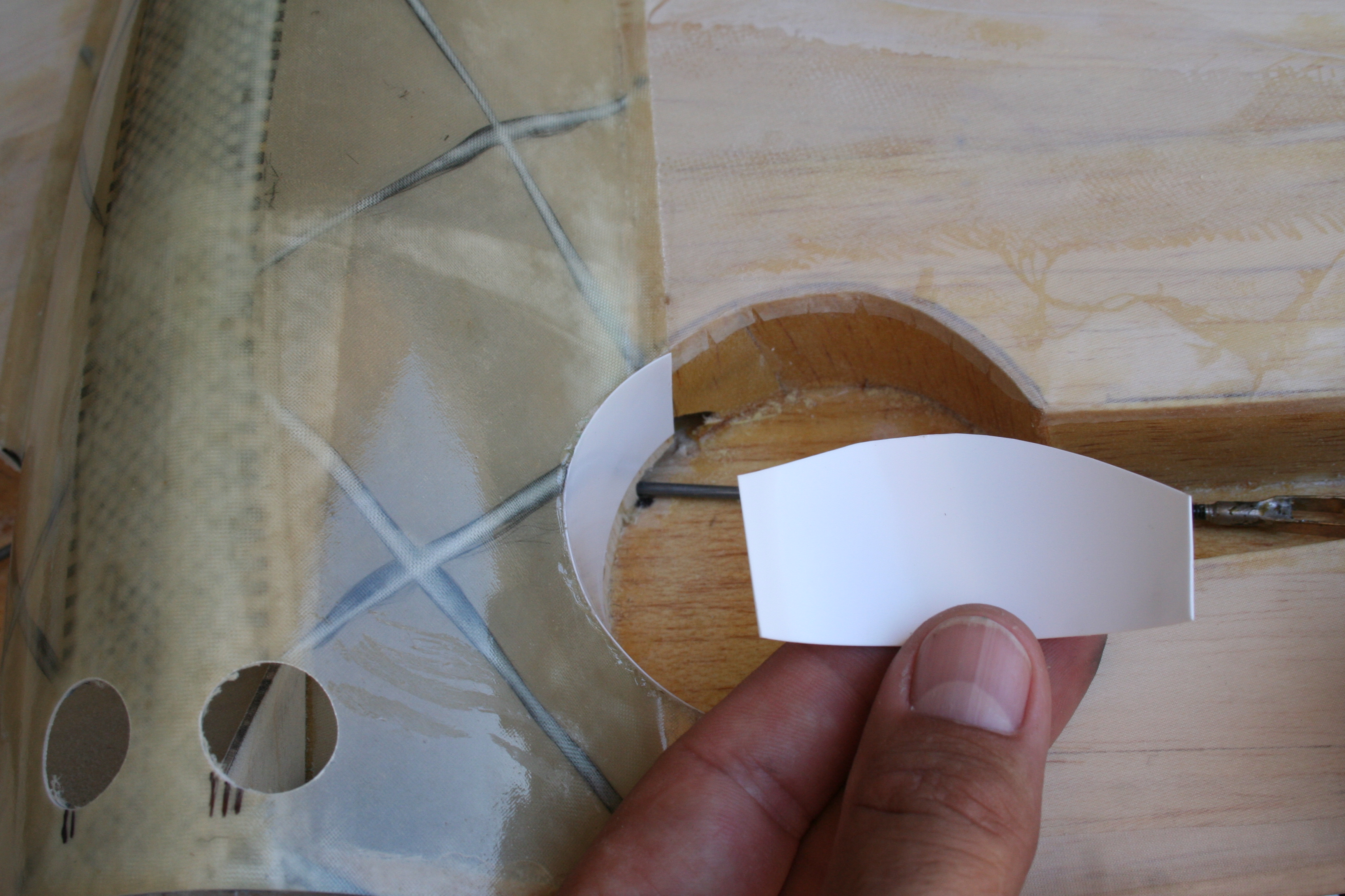
I cut pieces from the sides of the container that I could glue from the bottom (or top, depending on your perspective) of the well, and would extend just beyond the surface of the belly pan.
01-14-2017, 07:41 PM
#515
Thread Starter
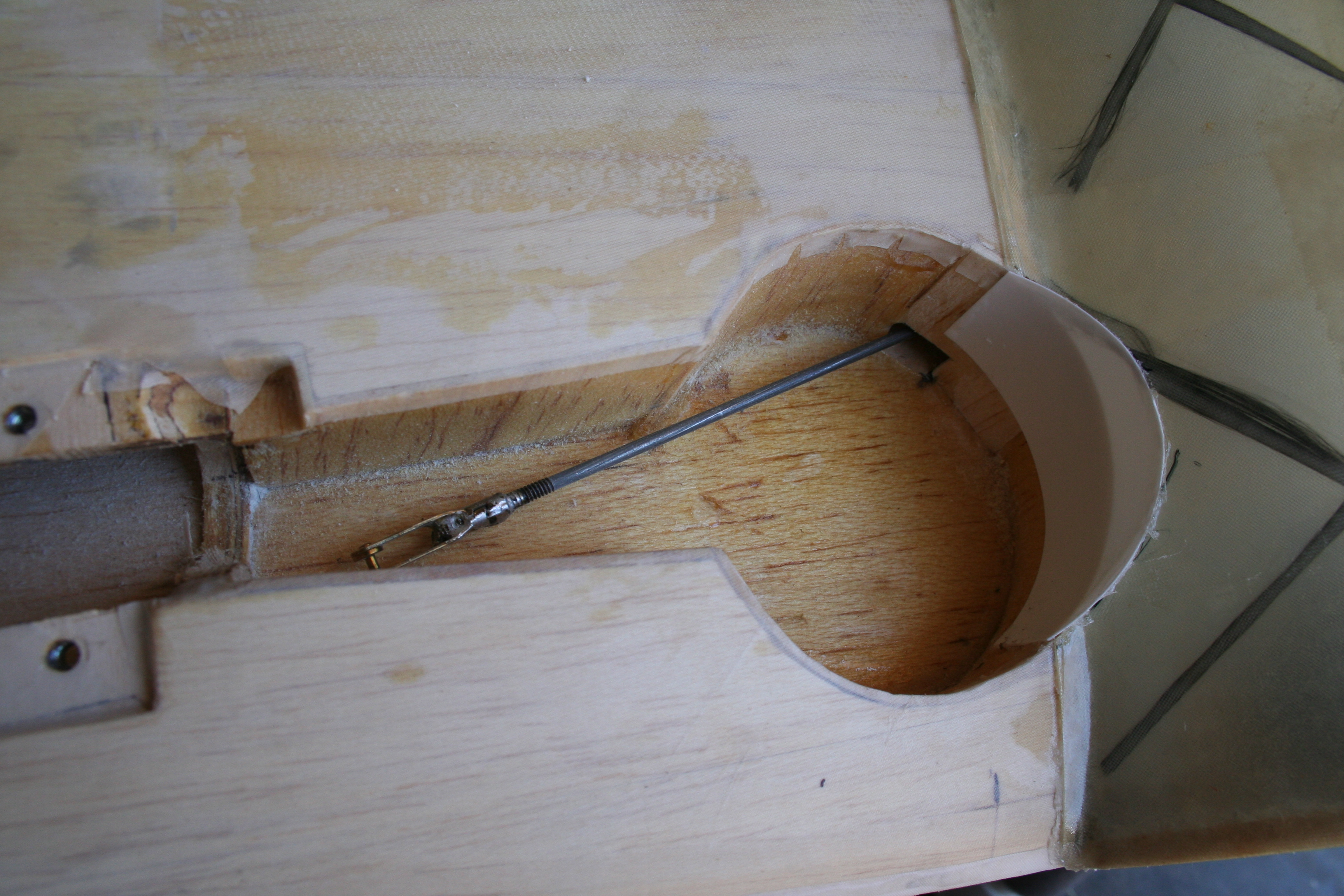
While the Omnistick glue is drying on the wheel wells, it is back to the fuse. I installed two Dubro Laser-Rod pushrod exits for the elevator, and one for the rudder. I also fabricated some sheet metal to form the tailwheel doors, which serve to hide the Dubro 40-sized tailwheel bracket in a more scale manner. Also visible in the picture are the installed 4-40 bolts that serve as elevator and rudder control rods.
01-14-2017, 07:52 PM
#516
Thread Starter
Time to paint!
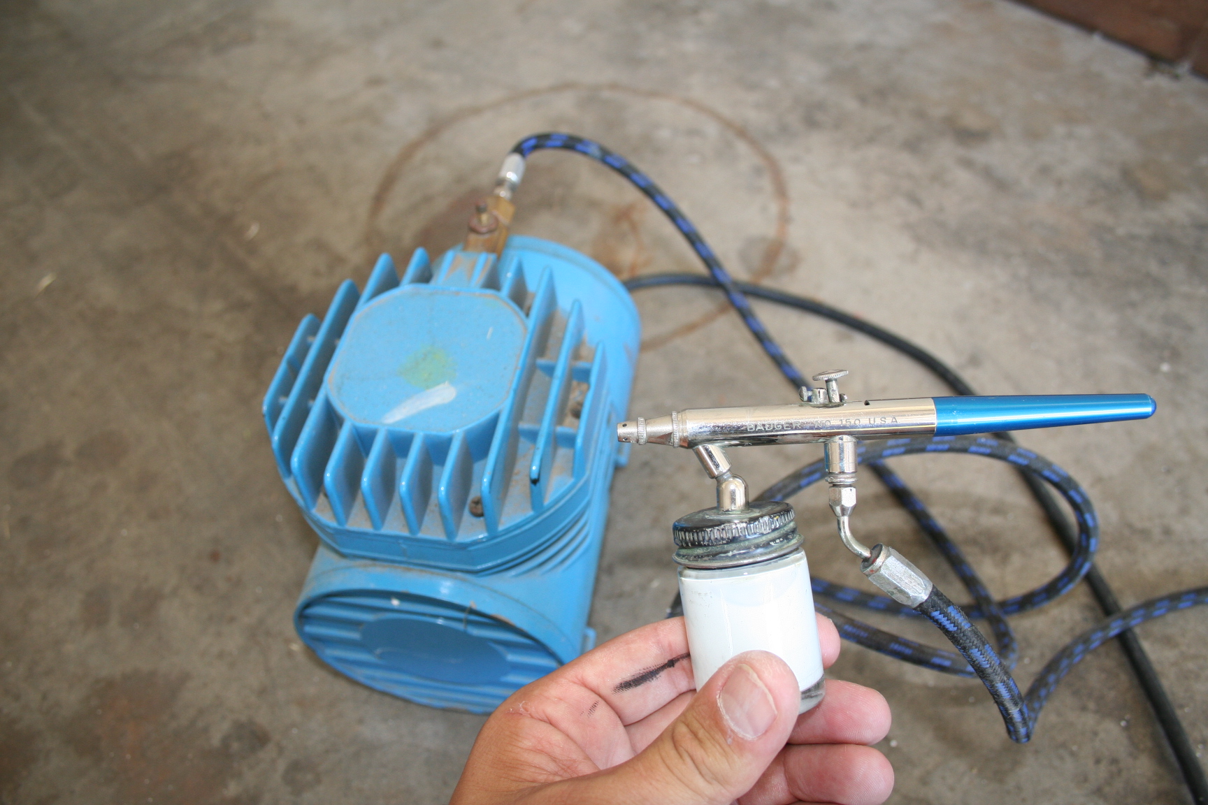
I pulled the cars out of the garage; began masking off, mixed the Klasskote paint, and started the compressor.
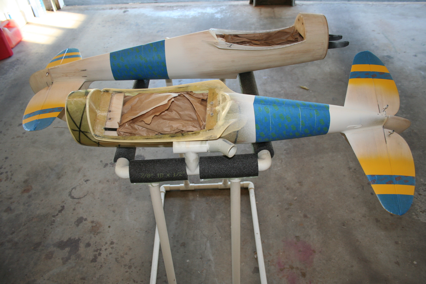
I actually have a second, all-wood, larger but "skinnified" (sorry Tommygun) version of the P-47 that my father-in-law also built for me, that I am painting at the same time. Here are the two planes, after white primer and yellow have been applied:
I pulled the cars out of the garage; began masking off, mixed the Klasskote paint, and started the compressor.
I actually have a second, all-wood, larger but "skinnified" (sorry Tommygun) version of the P-47 that my father-in-law also built for me, that I am painting at the same time. Here are the two planes, after white primer and yellow have been applied:
01-14-2017, 08:01 PM
#517
Thread Starter
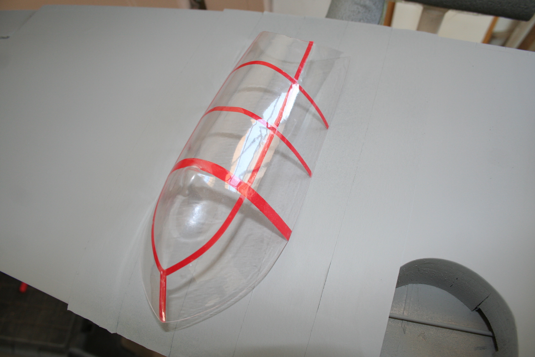
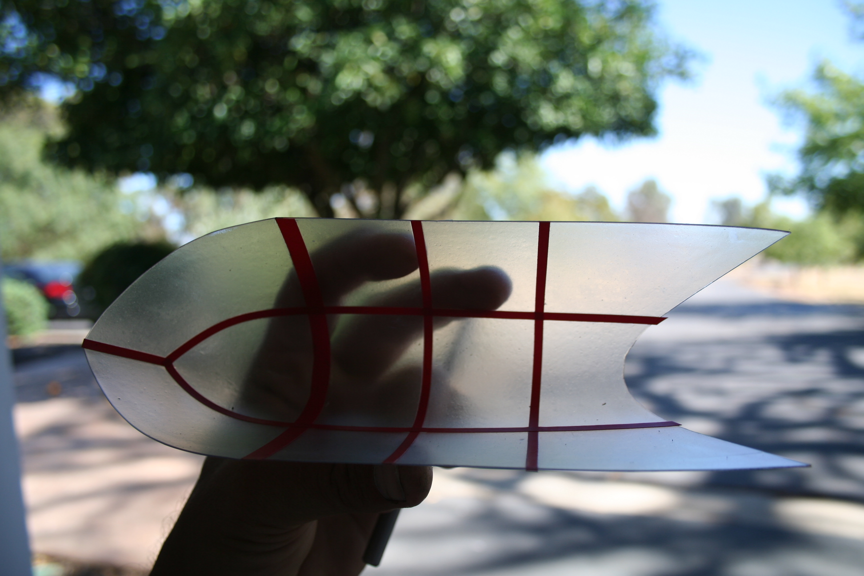
Next, I masked off the framework of both canopies and applied liquid frisket masking film with my airbrush. (Unfortunately, on the second canopy, pictured below, I forgot to mask off the bottom frame, so will have to partially respray this one, again. "Rookie" move!)
01-14-2017, 08:11 PM
#519
Thread Starter
With decals and clear coat, and everything installed, ready to fly, I weighed the P-47 detailed in this build. It came out to 6 3/4 pounds, finished weight.
Last edited by Iron Dog; 01-14-2017 at 08:13 PM.
