


Hobbistar 60 - from one aileron servo to two
 11-27-2013, 06:29 AM
#1
Senior Member
Thread Starter

This is one of several modifications to my trusty Hobbistar 60 planned for this winter... see also Stuffing a DLE 20 into a Hobbistar 60. In addition, I'll be converting the wing from rubber bands to bolt-on. That'll be documented in a future thread.
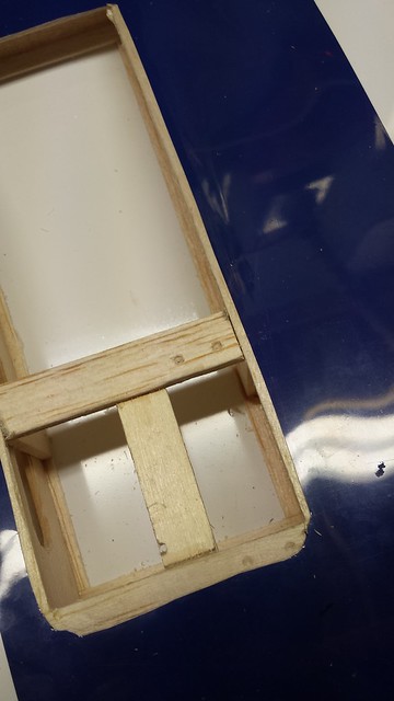
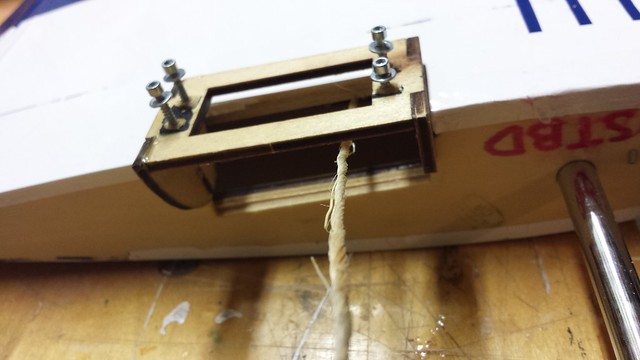
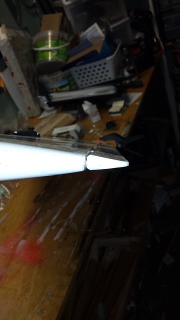
Here's the stock arrangement with the Hobbistar ailerons.
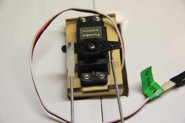
As you can see in the first picture, one of the L-bends slipped out of the servo arm. At the time I modified the linkages but stuck with the single servo.
Here's the stock arrangement with the Hobbistar ailerons.
As you can see in the first picture, one of the L-bends slipped out of the servo arm. At the time I modified the linkages but stuck with the single servo.
 11-27-2013, 06:50 AM
#2
Senior Member
Thread Starter
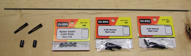
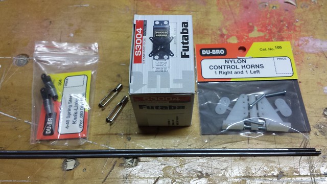
It was suggested to me that the plane would benefit from dual aileron servos. That seems reasonable to me - more strength, plus the ability to mix in flaperons and aileron differential. The other day I checked my own stock and made a trip to my LHS to pick up the remaining stuff I needed.
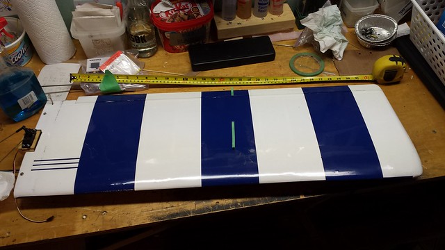
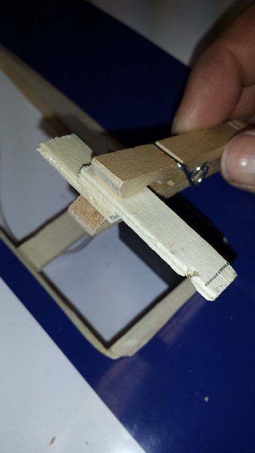
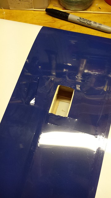
Next step was to find a location for the servo as close to the centre of the aileron as possible.
Take a deep breath, and... cut.
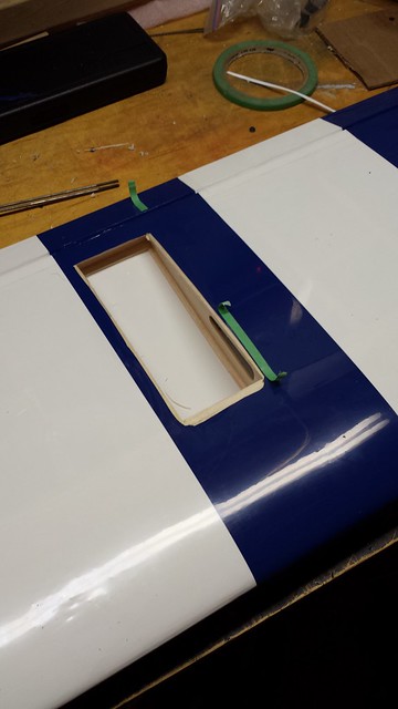
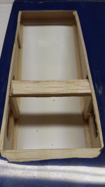
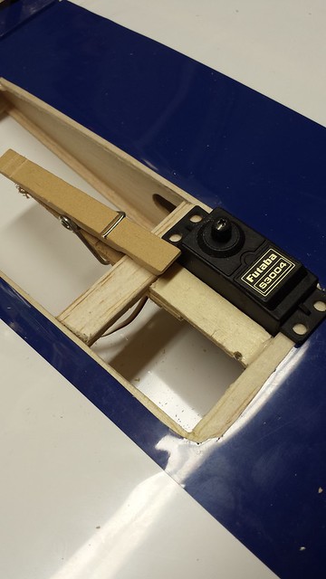
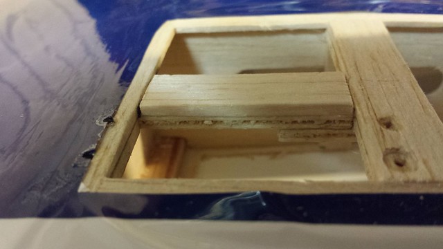
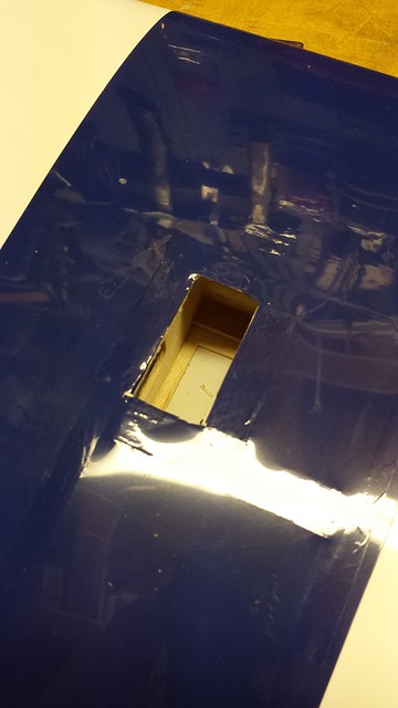
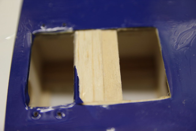
Framing for the servo is a fairly simple affair with plywood (salvaged from an orange crate) and basswood. I did some measuring and cut my pieces to length. Here's the first section complete.
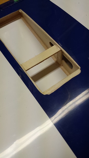
Next, I will add a longitudinal brace and cover the lateral one with sheeting so that the servo will sit level. I will have to splice some extra length into the servo wires but I've done that before:
http://www.grosbeakrc.ca/tutorials/splice.html
Next step was to find a location for the servo as close to the centre of the aileron as possible.
Take a deep breath, and... cut.
Framing for the servo is a fairly simple affair with plywood (salvaged from an orange crate) and basswood. I did some measuring and cut my pieces to length. Here's the first section complete.
Next, I will add a longitudinal brace and cover the lateral one with sheeting so that the servo will sit level. I will have to splice some extra length into the servo wires but I've done that before:
http://www.grosbeakrc.ca/tutorials/splice.html
 11-27-2013, 06:33 PM
#4
Senior Member
Thread Starter
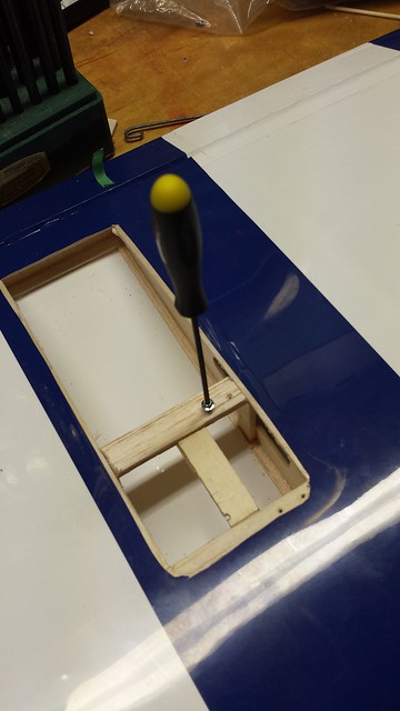
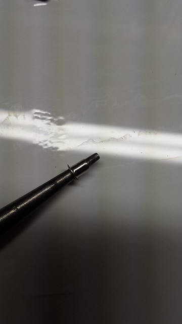
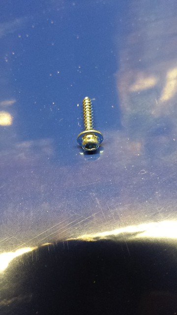
Marking the servo screw holes.
Holes all marked.
Time for my trusty pin vise.
Holes drilled, threading with servo screw. Some thin CA was drizzled in afterwards.
Holes all marked.
Time for my trusty pin vise.
Holes drilled, threading with servo screw. Some thin CA was drizzled in afterwards.
11-28-2013, 02:56 AM
#5
Senior Member
My Feedback: (1)

Join Date: Jan 2008
Location: MINSK, BELARUS
Posts: 205
Likes: 0
Received 0 Likes
on
0 Posts
Hi,
I also put dual ailerons servos and bolts tohold the wing on my Hobbistar because I didn't like like the way it was. (i followed the instructions from this website to do it http://www.modelaircraft.org/mag/ftg...22/22main.html ).
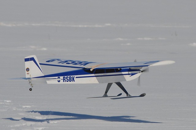
Then later, I converted it as a taildragger and used the "Dubro Super Strength Landing Gear" which gave me more space between the propeller and the ground.
I still enjoy to flying it from time to time, especially during winter with skis on it. It's a very nice and stable trainer.
Good luck!
I also put dual ailerons servos and bolts tohold the wing on my Hobbistar because I didn't like like the way it was. (i followed the instructions from this website to do it http://www.modelaircraft.org/mag/ftg...22/22main.html ).
Then later, I converted it as a taildragger and used the "Dubro Super Strength Landing Gear" which gave me more space between the propeller and the ground.
I still enjoy to flying it from time to time, especially during winter with skis on it. It's a very nice and stable trainer.
Good luck!
11-28-2013, 03:06 AM
#6
Senior Member
Thread Starter
Hi,
I also put dual ailerons servos and bolts tohold the wing on my Hobbistar because I didn't like like the way it was. (i followed the instructions from this website to do it http://www.modelaircraft.org/mag/ftg...22/22main.html ).
Then later, I converted it as a taildragger and used the "Dubro Super Strength Landing Gear" which gave me more space between the propeller and the ground.
I still enjoy to flying it from time to time, especially during winter with skis on it. It's a very nice and stable trainer.
Good luck!
Nice to know someone else enjoys this plane. Thanks for the link - I'll be saving that!
This one has also been converted to a tail dragger, and has had an extensive wing rebuild after I stuffed it in tree early in 2012. I too enjoy my Hobbistar on skis.
 11-28-2013, 03:18 AM
#7
Senior Member
Thread Starter
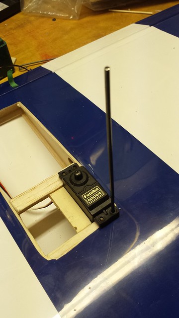
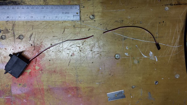
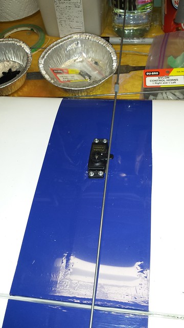
Now that the servo framing is complete it's time to determine the required servo lead lengths. I prefer spliced extensions to connectors where possible, so I starting by tying some string to the stock lead and fishing it through the wing.
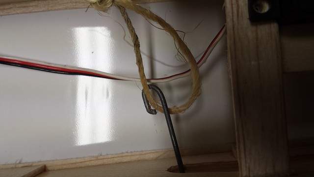
Propping the wing on the saddle, I could determine what length was needed. I will plug short extensions into the receiver and connect the aileron servos to those rather than plugging and unplugging directly to / from the receiver every time I go flying.
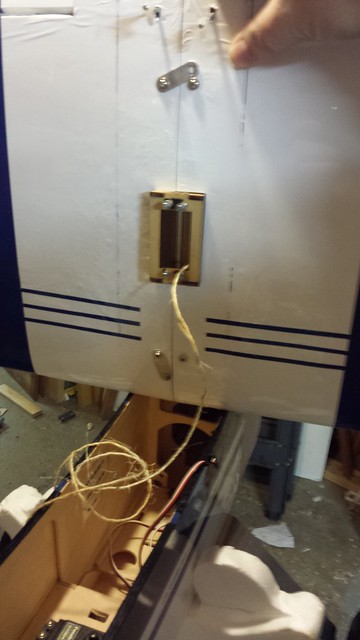
A mark on the string to show the required length.
Propping the wing on the saddle, I could determine what length was needed. I will plug short extensions into the receiver and connect the aileron servos to those rather than plugging and unplugging directly to / from the receiver every time I go flying.
A mark on the string to show the required length.
11-28-2013, 03:24 AM
#8
Senior Member
Thread Starter
Next, I gathered my splicing tools and supplies.
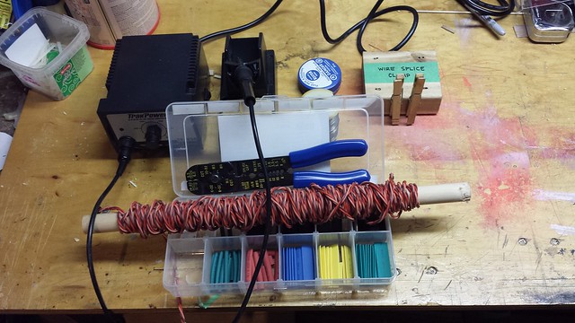
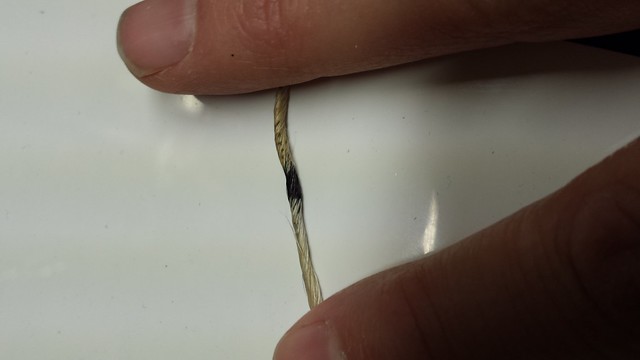
I measured and cut a 16" length of bulk servo wire.
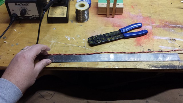
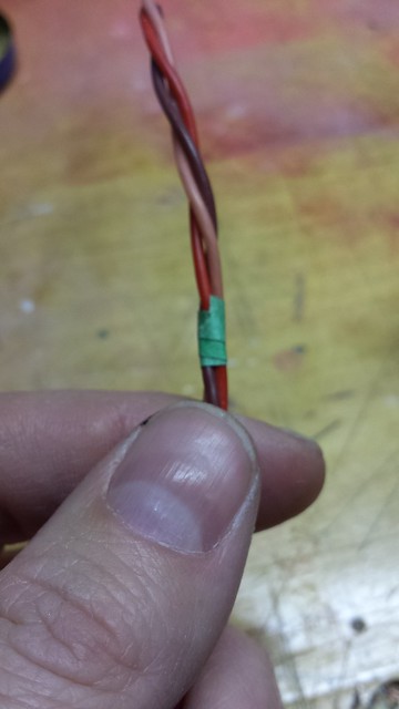
This bulk wire is braided - it just occurred to me to put a little tape on the wire a few inches from the ends to keep it from unraveling too much.
I measured and cut a 16" length of bulk servo wire.
This bulk wire is braided - it just occurred to me to put a little tape on the wire a few inches from the ends to keep it from unraveling too much.
11-28-2013, 03:29 AM
#9
Senior Member
Thread Starter
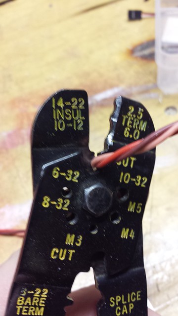
Next step is to separate the conductors...
... strip about 5mm (3/16") off the ends...
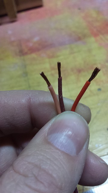
...twist the loose strands together...
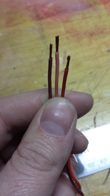
...and dip them in flux.
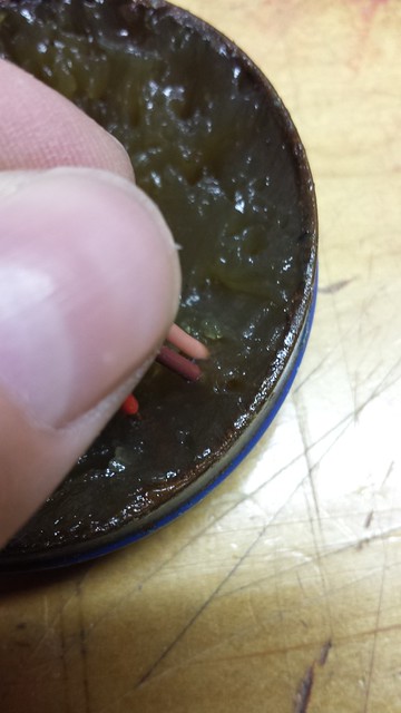
... strip about 5mm (3/16") off the ends...
...twist the loose strands together...
...and dip them in flux.
11-28-2013, 03:34 AM
#10
Senior Member
Thread Starter
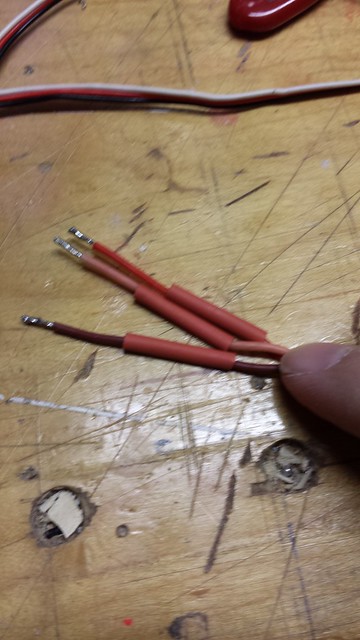
I follow that up by tinning the ends, 12 in all (3 conductors on each end of both extensions).
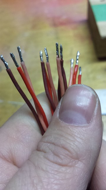
Both extensions are now complete.
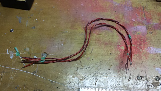
Next step... splicing the extensions into the servo leads.
Both extensions are now complete.
Next step... splicing the extensions into the servo leads.
11-28-2013, 07:32 PM
#12
Senior Member
Thread Starter
11-28-2013, 07:32 PM
#13
Senior Member
Thread Starter
A little more time on the project tonight.
My first task was to cut the servo wire. I like to cut in the middle just in case there are any problems - lots of wire left to work with on both sides.
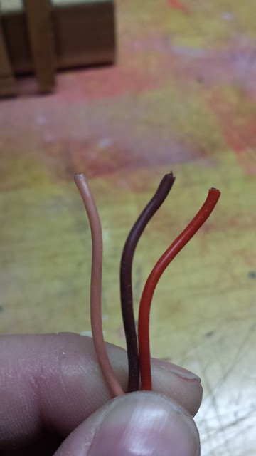
Next step was to separate the individual servo wires. I use my fingernails - less chance of nicking the wire.
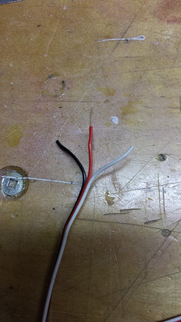
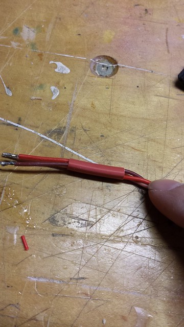
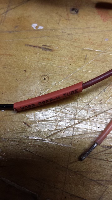
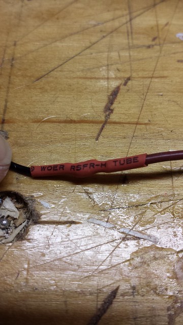
Sliding some heat shrink onto the splice. A big one to bundle all of the wires, and a small one for each splice.
My first task was to cut the servo wire. I like to cut in the middle just in case there are any problems - lots of wire left to work with on both sides.
Next step was to separate the individual servo wires. I use my fingernails - less chance of nicking the wire.
Sliding some heat shrink onto the splice. A big one to bundle all of the wires, and a small one for each splice.
11-28-2013, 07:41 PM
#14
Senior Member
Thread Starter
The colours of the splice match JR and the servos are Futaba - the colours are as follows.
Futaba
White - signal
Red - positive
Black - negative
JR
Orange - signal
Red - positive
Brown - negative
I follow the colour scheme when I'm splicing - makes for less confusion.
Next step - pick a wire from the splice braid and pin it in my shop-made splicing clamp with its corresponding servo wire. It's my habit to start with the negative.
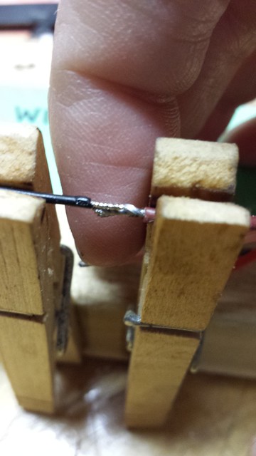
With the wires touching and my soldering station set to 700� F, all it takes is a bit of solder on the tip and a brief contact with the wires to get a nice splice.
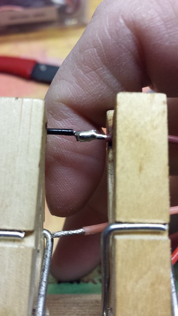
That done, I slid the heat shrink over the splice and shrunk it with the heat gun.
Futaba
White - signal
Red - positive
Black - negative
JR
Orange - signal
Red - positive
Brown - negative
I follow the colour scheme when I'm splicing - makes for less confusion.
Next step - pick a wire from the splice braid and pin it in my shop-made splicing clamp with its corresponding servo wire. It's my habit to start with the negative.
With the wires touching and my soldering station set to 700� F, all it takes is a bit of solder on the tip and a brief contact with the wires to get a nice splice.
That done, I slid the heat shrink over the splice and shrunk it with the heat gun.
11-28-2013, 07:47 PM
#15
Senior Member
Thread Starter
I followed that with the positive and the signal wires, then shrunk the large tube over the bundle of splices. Nice and neat. One set down, three to go.
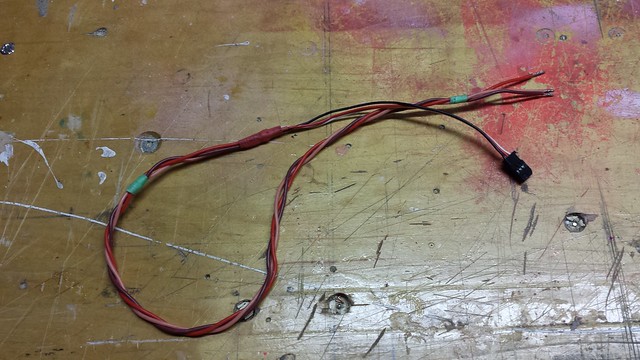
The servo end followed in the same manner. Once that was done I hooked it to my servo tester and verified the connections. All good.
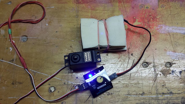
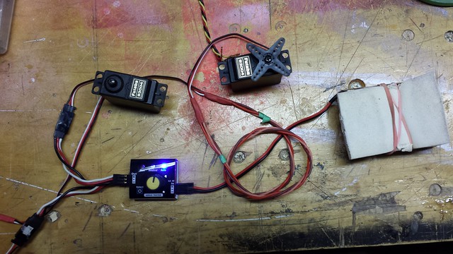
Next, I unboxed the new servo and tested it out before cutting the wire. Same procedure as the first, followed by a test of both with the extensions I'll be using. All good to go.
The servo end followed in the same manner. Once that was done I hooked it to my servo tester and verified the connections. All good.
Next, I unboxed the new servo and tested it out before cutting the wire. Same procedure as the first, followed by a test of both with the extensions I'll be using. All good to go.
11-28-2013, 07:54 PM
#16
Senior Member
Thread Starter
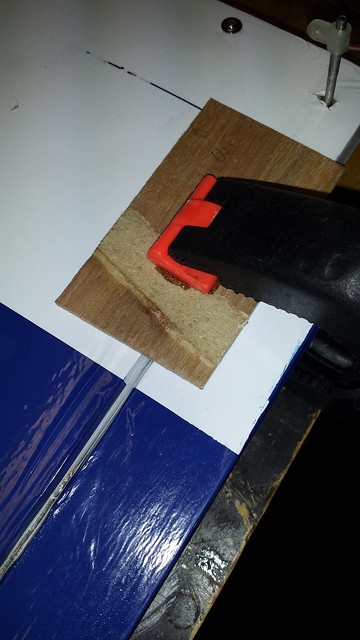
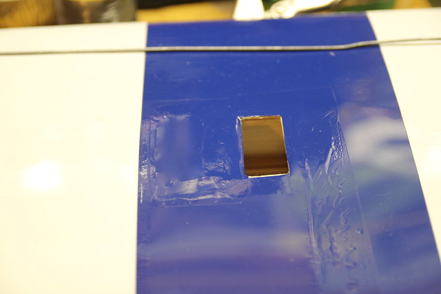
Servos complete and set aside, I turned my attention to the wings. First thing that occurred to me was that the longitudinal brace would need a piece of sheeting on top to bring it flush with the surrounding area for covering.
After the glued cured, I grabbed my covering iron and made sure the covering around the patch was all ironed down.
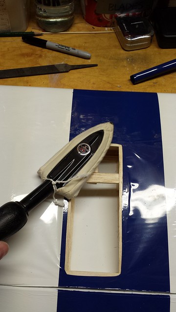
A little heat followed to tighten everything up.
Next step was to cut a patch. I had a piece just about the right size to do both wings.

After the glued cured, I grabbed my covering iron and made sure the covering around the patch was all ironed down.
A little heat followed to tighten everything up.
Next step was to cut a patch. I had a piece just about the right size to do both wings.
11-28-2013, 07:58 PM
#17
Senior Member
Thread Starter
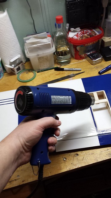
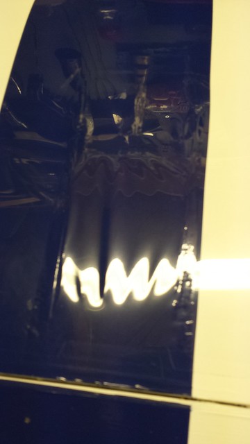
I started by ironing it on. I used too big a patch and some bubbles resulted.
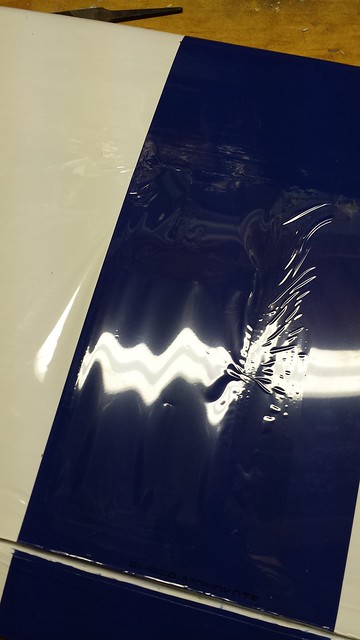
No worries - I resolved to use a smaller piece on the other wing and *****ed the bubbles with a T-pin.
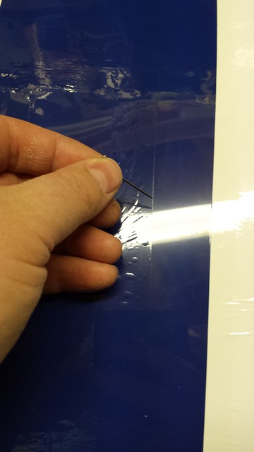
Afterwards I took the heat gun to the patch to shrink it tight. Much better.
No worries - I resolved to use a smaller piece on the other wing and *****ed the bubbles with a T-pin.
Afterwards I took the heat gun to the patch to shrink it tight. Much better.
11-28-2013, 08:02 PM
#18
Senior Member
Thread Starter
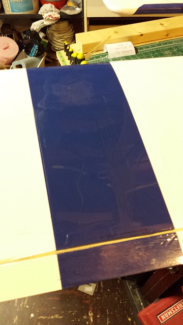
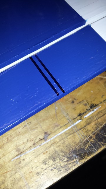
Now for the other wing. I cut the patch - smaller this time.
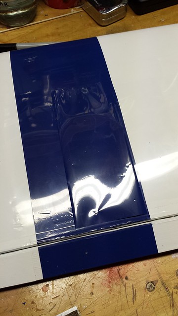
Ironed it on...
... and shrunk it tight. Then I cut the opening for the servo. Ruh roh... I cut too much.
No problem - a couple of little patches saved the day.
Next step... installing the servos.
Ironed it on...
... and shrunk it tight. Then I cut the opening for the servo. Ruh roh... I cut too much.
No problem - a couple of little patches saved the day.
Next step... installing the servos.
11-30-2013, 03:39 AM
#19
Senior Member
Thread Starter
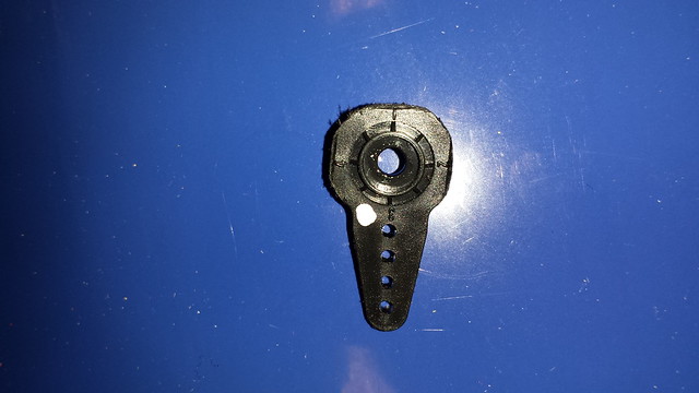
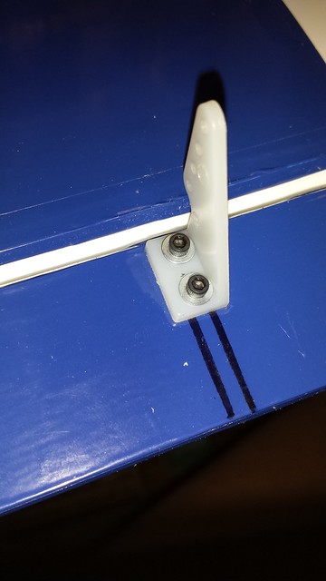
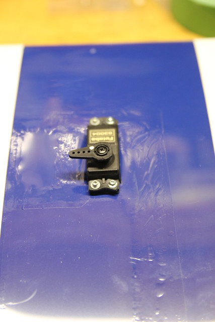
I use a punch to slide the grommets into the servo mounts.
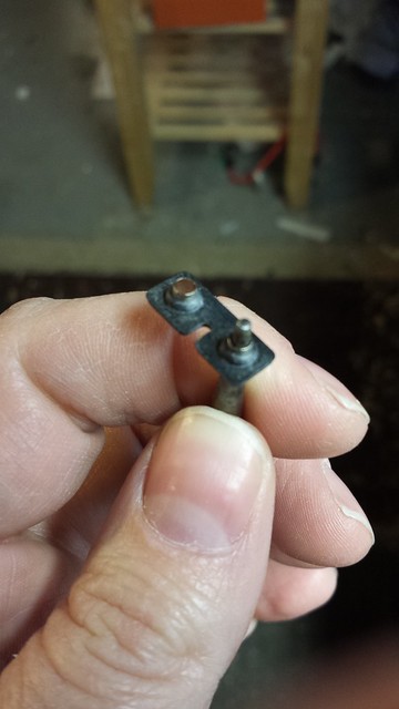
And I ditch the stock Phillips mounting screws in favour of socket head cap screws.
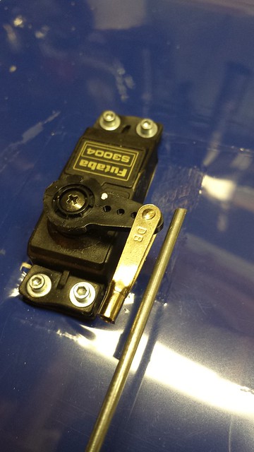
Next, I marked the arm I wanted to keep and cut the rest off, then cleaned up the cuts with a rotary tool.
And I ditch the stock Phillips mounting screws in favour of socket head cap screws.
Next, I marked the arm I wanted to keep and cut the rest off, then cleaned up the cuts with a rotary tool.

 11-30-2013, 03:48 AM
#22
Senior Member
Thread Starter
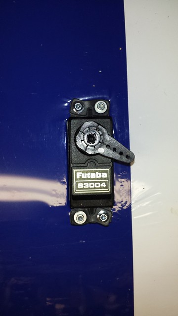
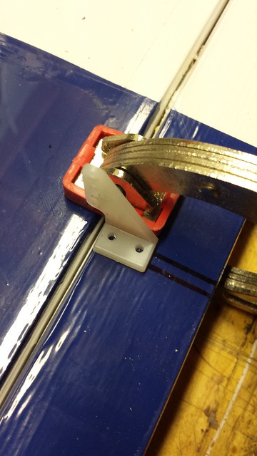
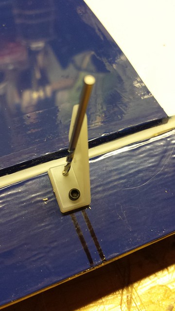
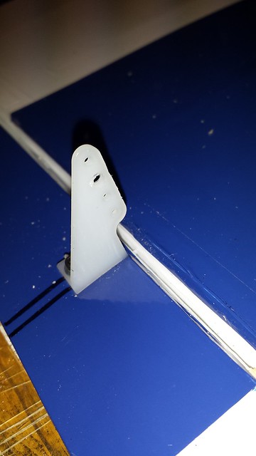
Horn mounted.
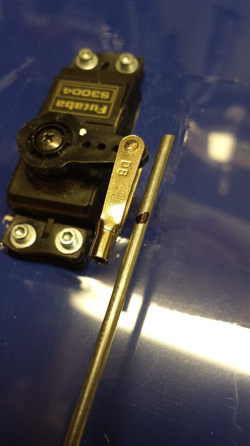
Hole enlarged for 4-40 ball link.
Ball link on.
Determining final push rod length - aileron is still locked at neutral and servo is held at neutral by servo tester.
Hole enlarged for 4-40 ball link.
Ball link on.
Determining final push rod length - aileron is still locked at neutral and servo is held at neutral by servo tester.
11-30-2013, 03:55 AM
#23
Senior Member
Thread Starter
Final length marked.
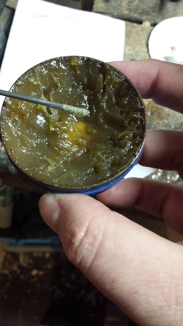
I used a solder-on clevis for the servo arm linkage. I removed the pushrod from the ball link and clamped it in a vise between soft jaws, then scuffed the mating surface with 320 grit sandpaper. That was followed by a wipe with 99% IPA and flux.
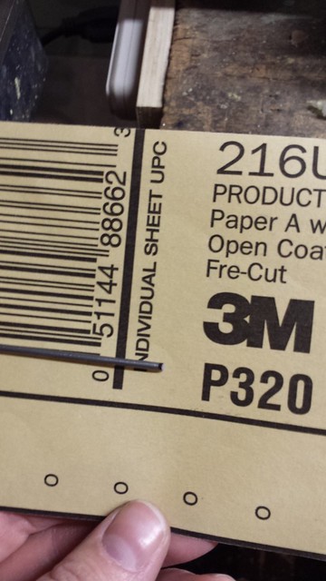
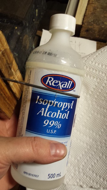
I used a solder-on clevis for the servo arm linkage. I removed the pushrod from the ball link and clamped it in a vise between soft jaws, then scuffed the mating surface with 320 grit sandpaper. That was followed by a wipe with 99% IPA and flux.
11-30-2013, 04:02 AM
#24
Senior Member
Thread Starter
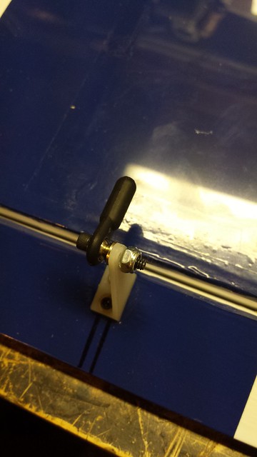
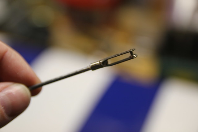
Slide on the clevis and we're go for solder.
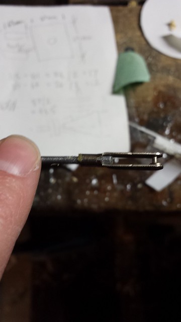
Soldering takes two hands so I didn't get any photos of the process, but here's the narrative. I turned my soldering station up to eleven (900� F) and held the tip to the push rod behind the clevis. When the flux started to sizzle I applied the solder to the portion of rod inside the clevis and let it flow into the clevis. Makes a good solid joint.
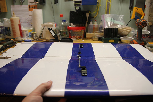
I connected the push rod. At this point I had another ruh roh moment - are we seeing a pattern here? I held up the two wings, ailerons together. Looks like I put the servo bays against different ribs!
Soldering takes two hands so I didn't get any photos of the process, but here's the narrative. I turned my soldering station up to eleven (900� F) and held the tip to the push rod behind the clevis. When the flux started to sizzle I applied the solder to the portion of rod inside the clevis and let it flow into the clevis. Makes a good solid joint.
I connected the push rod. At this point I had another ruh roh moment - are we seeing a pattern here? I held up the two wings, ailerons together. Looks like I put the servo bays against different ribs!
11-30-2013, 04:07 AM
#25
Senior Member
Thread Starter
Luckily, this was a quick and easy fix. I opened up some of the covering and worked a piece of basswood to rest against the longitudinal brace.
Cover the old bay and we're back on track.
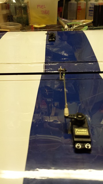
Servo in.
Linkage complete. That's more like it!
Cover the old bay and we're back on track.
Servo in.
Linkage complete. That's more like it!