Stuffing a DLE 20 into a Hobbistar 60
 11-23-2013, 07:09 PM
#1
Senior Member
Thread Starter

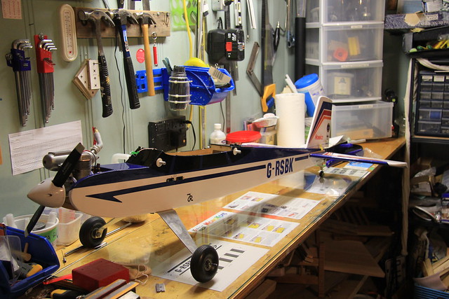
The time has come for my trusty Hobbsitar 60 trainer to say goodbye to glow and hello to gas. A little history:
Bought it as a shiny new RTF in the spring of 2011 for training at my club's flight school. Here it is all fresh, new and ready.

It was a great trainer and served me well. In the spring of 2012 I stuffed it in a tree and over the winter of 2012/2013 I rebuilt the badly damaged wing and converted it to a tail dragger. It last flew, on skis, early in 2013.

The last flight was a great success, but I decided I wouldn't fly it again until the slimer was gone and a gasser had taken its place. In the early summer of 2013 I bought an RCGF 32 to put in my Pulse 125, from which the DLE 20 would come for the Hobbistar.
I started the transformation this summer by removing the OS 65 LA engine and selling it along with all of my glow-related equipment. The installation of the RCGF 32 into the Pulse 125 is almost complete, and it's time to get started on this project.
Bought it as a shiny new RTF in the spring of 2011 for training at my club's flight school. Here it is all fresh, new and ready.
It was a great trainer and served me well. In the spring of 2012 I stuffed it in a tree and over the winter of 2012/2013 I rebuilt the badly damaged wing and converted it to a tail dragger. It last flew, on skis, early in 2013.
The last flight was a great success, but I decided I wouldn't fly it again until the slimer was gone and a gasser had taken its place. In the early summer of 2013 I bought an RCGF 32 to put in my Pulse 125, from which the DLE 20 would come for the Hobbistar.
I started the transformation this summer by removing the OS 65 LA engine and selling it along with all of my glow-related equipment. The installation of the RCGF 32 into the Pulse 125 is almost complete, and it's time to get started on this project.
 11-23-2013, 07:16 PM
#2
Senior Member
Thread Starter
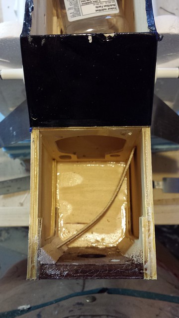
As shown in the previous photos, the OS 65 LA lived between two cowl cheeks. The DLE wouldn't fit so after a thorough cleaning of the entire airplane, they were the first things to go.
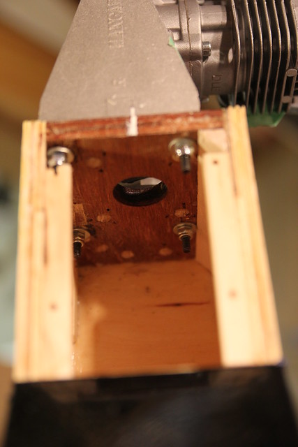
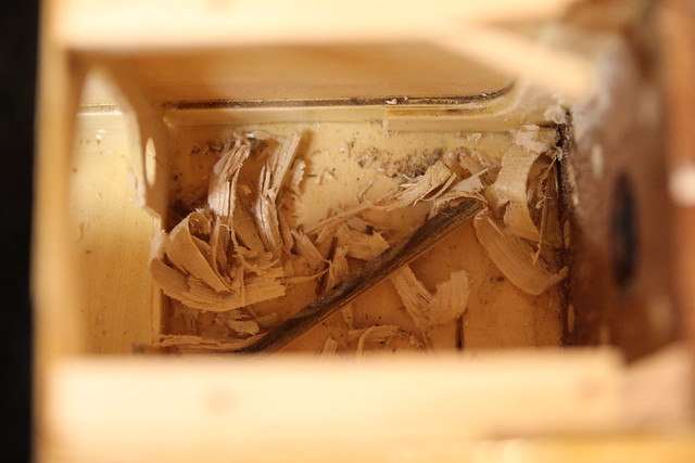
There's no way I could install the ignition components and fuel system through the center of the fuselage, so the next step was to expose the front compartment by removing the upper panel.
There's no way I could install the ignition components and fuel system through the center of the fuselage, so the next step was to expose the front compartment by removing the upper panel.
11-23-2013, 07:22 PM
#3
Senior Member
Thread Starter
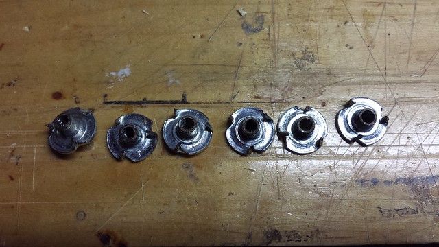
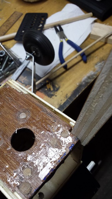
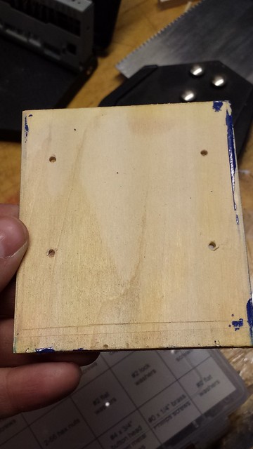
On the inside of the firewall are six blind nuts - four for the motor mounts and two for the long-gone nose gear mount. They were removed by threading in a 4mm bolt...
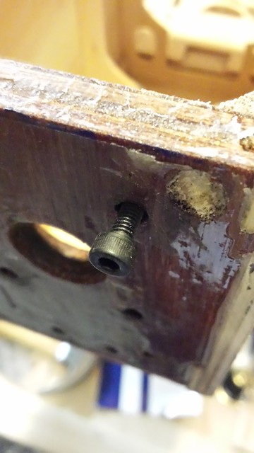
... and tapping on it until the blind nut came loose. They weren't glued in place so they came quietly.
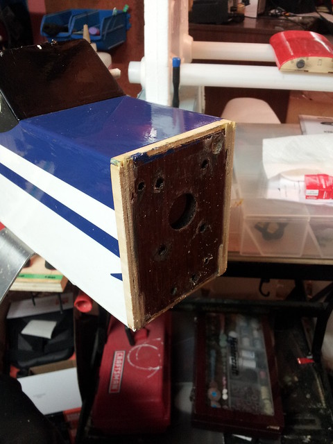
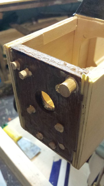
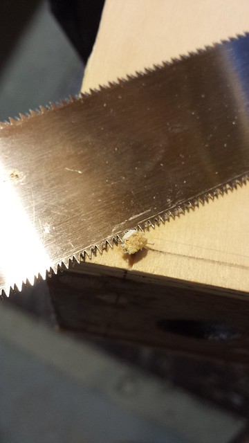
Next step was to drill out all of the holes (8 x 1/4" and 1 x 3/8"), clamp on a back plate...
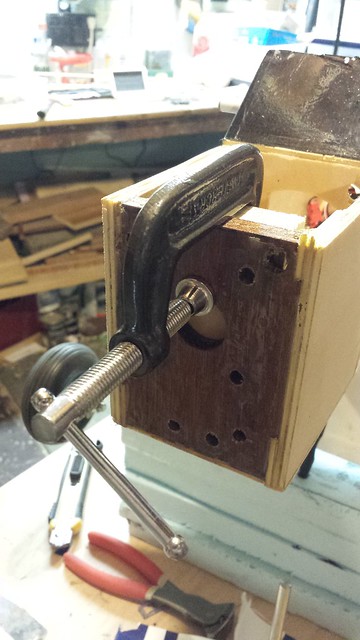
... And tap in some dowels.
... and tapping on it until the blind nut came loose. They weren't glued in place so they came quietly.
Next step was to drill out all of the holes (8 x 1/4" and 1 x 3/8"), clamp on a back plate...
... And tap in some dowels.
11-23-2013, 07:28 PM
#4
Senior Member
Thread Starter
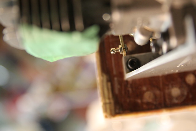
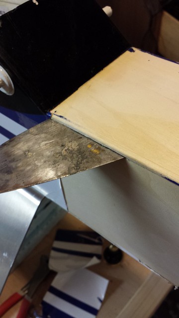
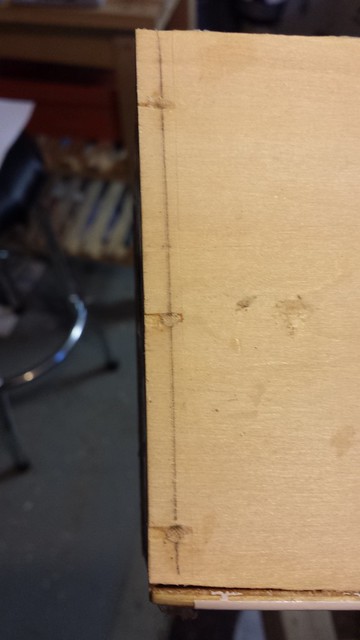
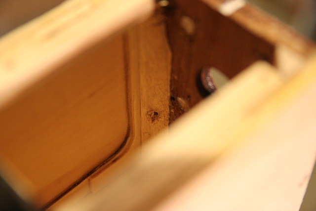
While I was taking a look inside the front compartment I noticed that the starboard tri-stock brace had separated from the firewall. That had to come out.
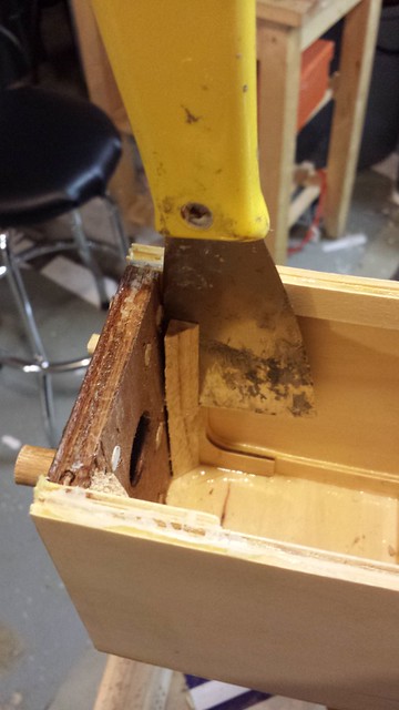
I soon discovered that the starboard fuselage skin had separated from the firewall too.
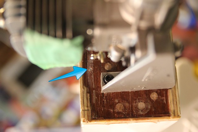
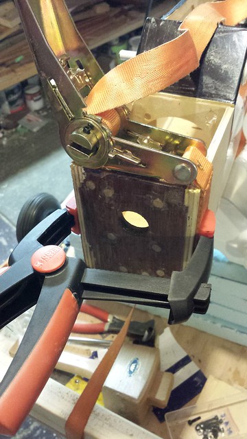
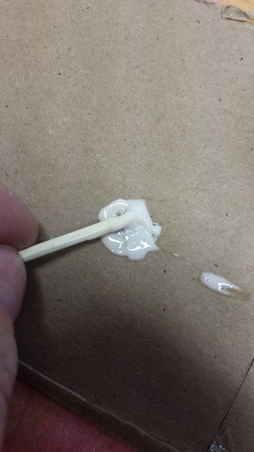
That got some glue...
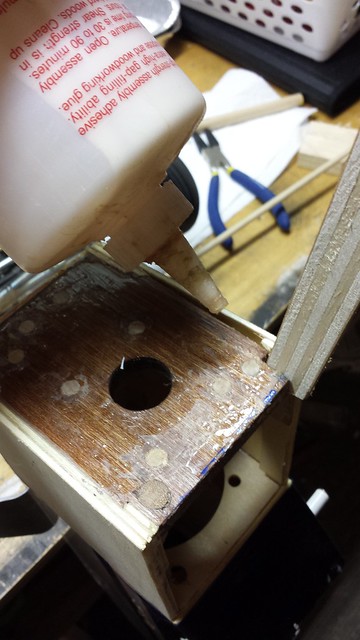
...and got clamped up. I will definitely be pinning this firewall.
I soon discovered that the starboard fuselage skin had separated from the firewall too.
That got some glue...
...and got clamped up. I will definitely be pinning this firewall.
11-23-2013, 07:35 PM
#5
Senior Member
Thread Starter
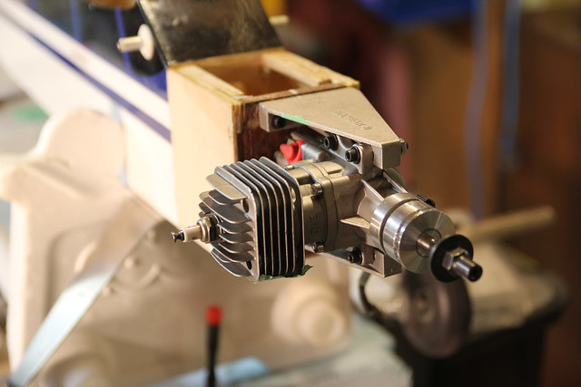
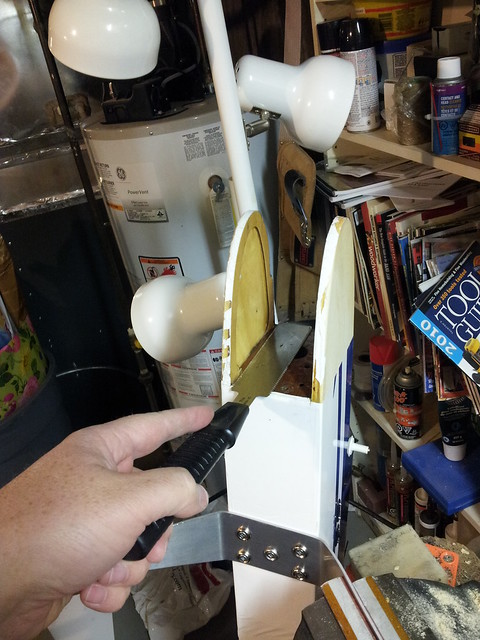
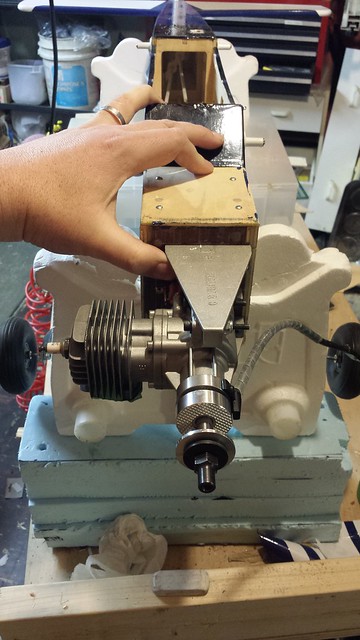
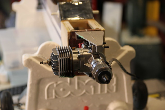
While the glue was curing I held the DLE 20 up to the firewall. Ruh roh... that mount is too wide, and if they make a narrower one I haven't seen it.

Time to think outside the box.
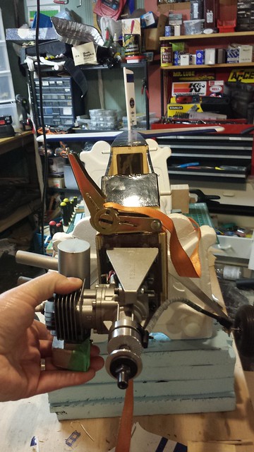
I'll be designing and building a custom cowl so accommodating this configuration will be no problem.
Time to think outside the box.
I'll be designing and building a custom cowl so accommodating this configuration will be no problem.
11-24-2013, 06:04 PM
#6
Senior Member
Thread Starter
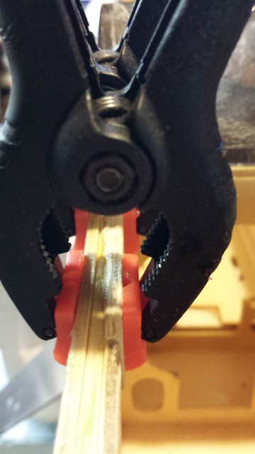
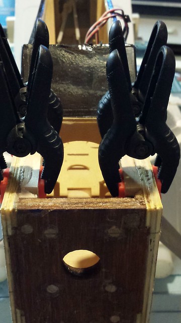
Replaced the separated tri-stock - Here it is glued and braced to cure.
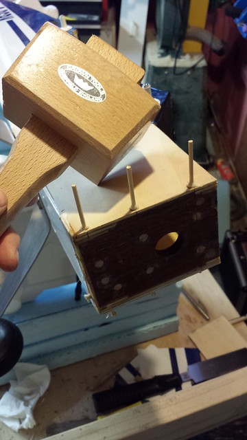
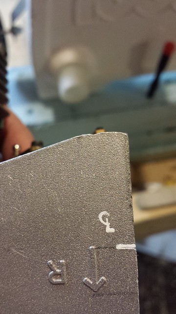
Marking the holes to pin the firewall.
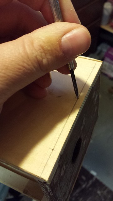
The pins are bamboo skewers. I cut them to length, then chuck them in the drill and run them against some sandpaper to taper an end.
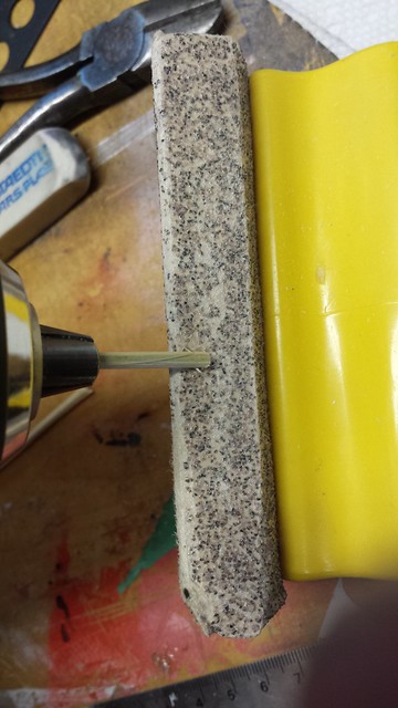
Presto.
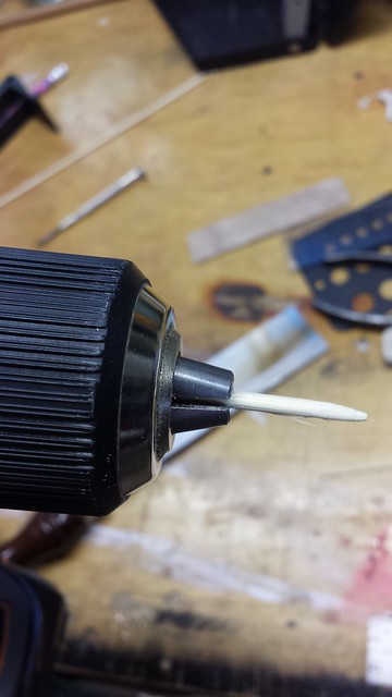
Marking the holes to pin the firewall.
The pins are bamboo skewers. I cut them to length, then chuck them in the drill and run them against some sandpaper to taper an end.
Presto.
 11-24-2013, 06:11 PM
#8
Senior Member
Thread Starter
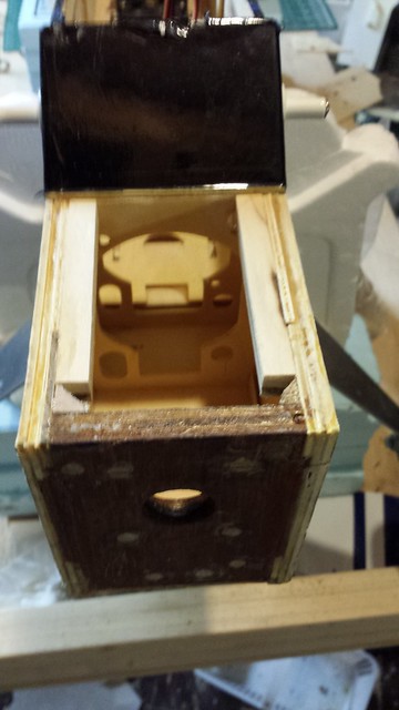
Next step - a mounting block for the top forward access hatch. Here are two shims and two mounting blocks.
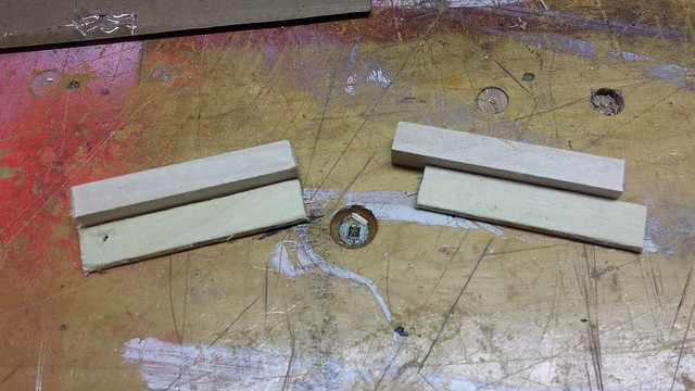
Shims are glued and clamped.
Marking the hatch for the mounting holes.
Holes drilled.
Shims are glued and clamped.
Marking the hatch for the mounting holes.
Holes drilled.
11-24-2013, 06:14 PM
#9
Senior Member
Thread Starter
I'm using #4 x 1/2" button head screws that came with the RTL Fastener Master Builder Assortment.
Mounting blocks glued and clamped.
Mounting blocks cured and ready.
Mounting blocks glued and clamped.
Mounting blocks cured and ready.
11-24-2013, 06:19 PM
#10
Senior Member
Thread Starter
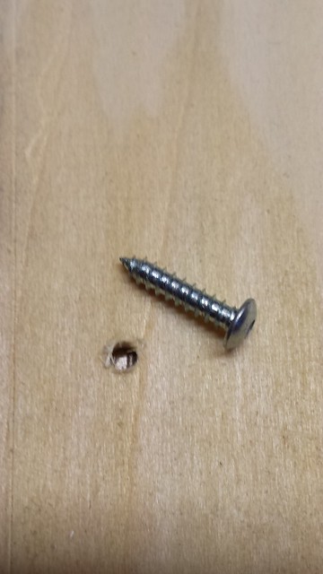
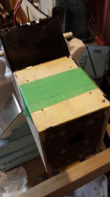
Hatch cover taped in place.
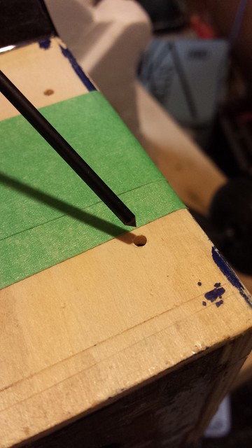
Using a transfer punch to mark the drilling point.
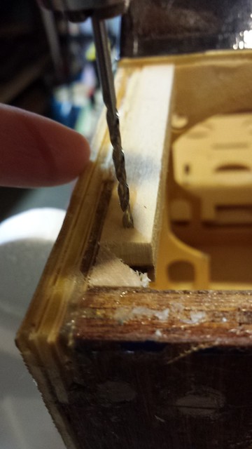
Using a hand drill for control and a brad point bit for a nice clean hole.
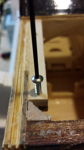
Threading the screw holes. I drizzled some CA into them afterwards.
Using a transfer punch to mark the drilling point.
Using a hand drill for control and a brad point bit for a nice clean hole.
Threading the screw holes. I drizzled some CA into them afterwards.


 11-25-2013, 03:38 PM
#15
I would put the servos in the tail section, and you might want to build a hatch in the tail to offset the weight of the gas power plant. Of course the landing gear will have to be beefed up a lot because the total weight once finished and balanced will be much more than originally. Not to mention the weight added while reinforcing the nose.
Good luck with the project! One thing is for sure, it will fly very different...
Gerry
Good luck with the project! One thing is for sure, it will fly very different...
Gerry
11-25-2013, 05:55 PM
#17
Senior Member
Thread Starter

I would put the servos in the tail section, and you might want to build a hatch in the tail to offset the weight of the gas power plant. Of course the landing gear will have to be beefed up a lot because the total weight once finished and balanced will be much more than originally. Not to mention the weight added while reinforcing the nose.
Good luck with the project! One thing is for sure, it will fly very different...
Gerry
Good luck with the project! One thing is for sure, it will fly very different...
Gerry
You and me both!
 11-25-2013, 05:56 PM
#18
Senior Member
Thread Starter
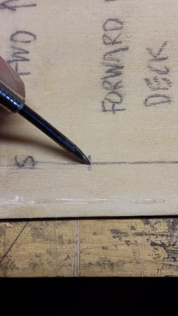
This evening I turned my attention to mounting the engine. I started by marking the centre lines on the firewall.
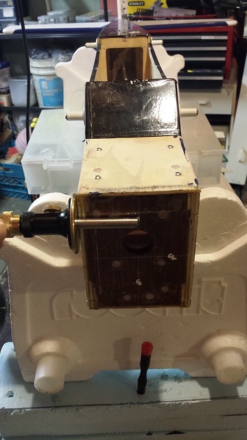
Then I marked the thrust line of the DLE 20 on the motor mount.
Seems to me that the thrust line should be centred laterally on the firewall. With that in mind, here's where the engine will go, at least from a side-to-side perspective.
The current port side mounting bolt holes are too close to the side of the fuselage, so I plan to drill new ones.
11-28-2013, 11:17 AM
#20
Senior Member
Thread Starter
I set it aside while I waited for feedback on a thrust angle question.
In the meantime I've been working on the conversion to dual aileron servos.
In the meantime I've been working on the conversion to dual aileron servos.
11-28-2013, 04:54 PM
#21

My Feedback: (7)
If you are going to use a large size 4 stroke then you will have something to worry about, that dle 20 will want to spin a 15-6 prop so I think you will have prop clearance more than anything else. If anything just leave the motor in the center of the fire wall centered on x and y and just use different length standoffs to get about I think 3 degrees will be about enough so the planes left side will be about quarter inch longer than the planes right side.
11-28-2013, 05:28 PM
#22

HMMM that DL and the added re-enforcing weighs just about twice what the OS weighs and you've mounted it in about the same location as the OS. How do you intend to balance the plane with this extra nose weight? Nose to tail ratio from the CofG would be about 4:1. OS is about 18 oz divided by 4 is 4.5 oz minimum as far back in the tail to balance. Think about doubling the size of your elevator and rudder and using less deflection to do the job. You may need the extra surface area to effectively move the extra mass of the engine about the axis of the plane especially at lower air speeds. That landing gear may prove to be inadequate for anything but a smooth landing. If it flexes to much it might be hard on prop tips. We have pressed out the axles on the Dubro bolt on axles then fed the same diameter piano wire straight through both sides, very strong but it doesn't flex at all. You can see the result of a similar gear on my heavy lifter where the plane weights 7 lbs and is carrying close to 23 lbs in lead. On landing it hit hard but suffered no ill effects.
Dennis
http://www.youtube.com/watch?v=vBgWUceKmR0
2;10 into the video shows the final flight including the hard landing. If you look carefully you can see the wire stretching across the landing gear.
Dennis
http://www.youtube.com/watch?v=vBgWUceKmR0
2;10 into the video shows the final flight including the hard landing. If you look carefully you can see the wire stretching across the landing gear.
11-30-2013, 04:28 AM
#23
Senior Member
Thread Starter
If you are going to use a large size 4 stroke then you will have something to worry about, that dle 20 will want to spin a 15-6 prop so I think you will have prop clearance more than anything else. If anything just leave the motor in the center of the fire wall centered on x and y and just use different length standoffs to get about I think 3 degrees will be about enough so the planes left side will be about quarter inch longer than the planes right side.
HMMM that DL and the added re-enforcing weighs just about twice what the OS weighs and you've mounted it in about the same location as the OS. How do you intend to balance the plane with this extra nose weight? Nose to tail ratio from the CofG would be about 4:1. OS is about 18 oz divided by 4 is 4.5 oz minimum as far back in the tail to balance. Think about doubling the size of your elevator and rudder and using less deflection to do the job. You may need the extra surface area to effectively move the extra mass of the engine about the axis of the plane especially at lower air speeds. That landing gear may prove to be inadequate for anything but a smooth landing. If it flexes to much it might be hard on prop tips. We have pressed out the axles on the Dubro bolt on axles then fed the same diameter piano wire straight through both sides, very strong but it doesn't flex at all. You can see the result of a similar gear on my heavy lifter where the plane weights 7 lbs and is carrying close to 23 lbs in lead. On landing it hit hard but suffered no ill effects.
Dennis
http://www.youtube.com/watch?v=vBgWUceKmR0
2;10 into the video shows the final flight including the hard landing. If you look carefully you can see the wire stretching across the landing gear.
Dennis
http://www.youtube.com/watch?v=vBgWUceKmR0
2;10 into the video shows the final flight including the hard landing. If you look carefully you can see the wire stretching across the landing gear.
I'm pretty sure we'll be okay on weight with the stock control surfaces. As for weight and balance, the stock fuel tank was right behind the firewall; this one will be much closer to the CG. I will move the batteries back for balance if needed. And I will reinforce the landing gear if necessary. This is not the stock gear:
 12-01-2013, 09:49 AM
#24
Senior Member
Thread Starter
I started the mounting process by holding the engine in place and marking the first bolt hole. I drilled that hole, then bolted the engine to the plane with the one bolt. Not a good idea for flying, but perfectly stable in the shop.
In the process of marking the other holes I re-learned that the beam mount bolts were too long and get in the way of the transfer punch I was using. Out came the rotary tool and soon after the bolts were shorter. Note the extra nuts - it's a habit of mine to thread a nut on first to help re-form the threads after the cut.
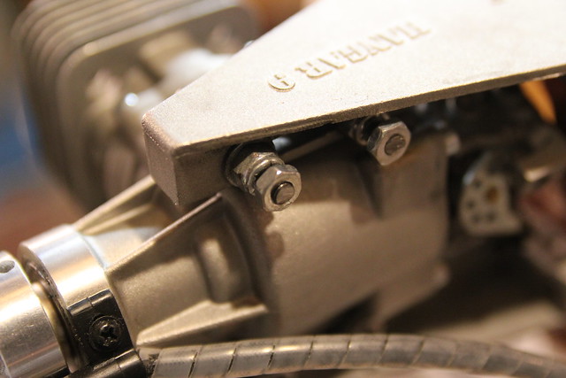
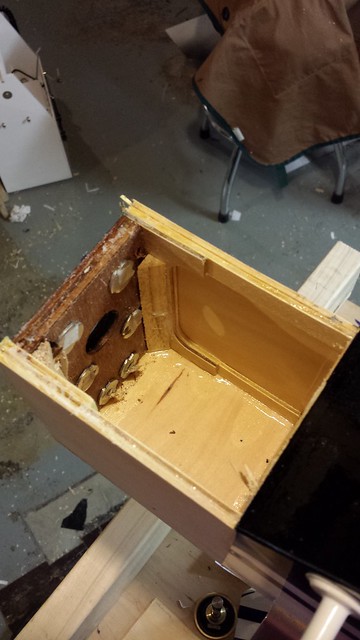
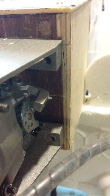
In the end I decided not to relocate the bolt holes in the beam mounts. As a result, the port side bolt holes in the firewall came through the tri-stock...
... so I removed the tri-stock. Some of it will reappear a few posts down.
In the process of marking the other holes I re-learned that the beam mount bolts were too long and get in the way of the transfer punch I was using. Out came the rotary tool and soon after the bolts were shorter. Note the extra nuts - it's a habit of mine to thread a nut on first to help re-form the threads after the cut.
In the end I decided not to relocate the bolt holes in the beam mounts. As a result, the port side bolt holes in the firewall came through the tri-stock...
... so I removed the tri-stock. Some of it will reappear a few posts down.