ORIGINAL: spacerockman
Simple question. Is there a preferred order for channel setup: Ailerons, throttle, elevator, rudder?
I typically use a 7-channel Hitec receiver with seperate aileron and elevator servos.
With most transmitters, channel assignemnt is fixed
.
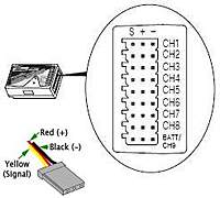
Receiver - Channel Assignments, which to use as determined by different brands of TX
extract: "ORIGINAL: A.T.
RX...............Channel Assignments as determined by different brands of TX
RX.......Futaba/Hitec....Graupner/JR......Multiplex.....Sanwa......Robbe
Ch 1.....ailerons............throttle...........ailer ons.......elevator....ailerons
Ch 2.....elevator...........ailerons...........elevat or......ailerons.....elevator
Ch 3.....throttle............elevator..........rudder .........throttle.......rudder
Ch 4.....rudder..............rudder............thrott le........rudder........throttle
Ch 5.....Retracts...........Retracts..........Retract s.......Retracts....Retracts
Ch 6.....Flaps................Flaps..............Flap s............Flaps.........Flaps.
NB: the default channel assignments on the Futaba MZ are different from the default channel assignments on the Futaba 9c and other older Futaba transmitters.
MZ= elevator, rudder, throttle, aileron
9c = aileron,elevator,throttle,rudder
The Spektrum modules for Futaba/Hitectranslate the channel mappings to the JR/Spektrum standard of throttle,aileron,elevator,rudder.
If you use the MZ module with a transmitter that has the older Futaba mappings, the aileron, elevator and rudder will come out on different pins on the Spektrum receiver.
Avoid Signal Lag
With some transmitters such as Hitec Aurora 9, user can opt to choose / select any receiver ports.
Thus if using multiple ailerons, elevators etc user can select say port 2&3 for aileron and ports 6&7 for elevator so to have the closest
spacing and avoid any signal lag between ports."
Given you typically use Hitec systems, please refer to:
.
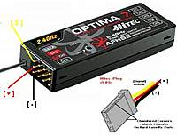
Hitec - Receiver & Optima Transceiver - Polarity of Receiver Servo Ports (channels), Plugs and Leads.
quote:
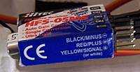
1 & 2.Servo polarity - all known servo brands have used black as negative and red as positive for many years,
the oddity being JR (and clones thereof) which use brown for negative.
The signal lead is usually Yellow, White, Blue or Orange - refer:
Servo - Wiring Diagrams = use with other brand RX. may assist.
3. Batt is simply a suggested port to separate leads for beginner's ready reference, explained:
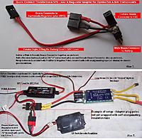
Optima Transceiver (RX) - Multiple Batteries may be installed - Dual batteries for redundancy or even one for each servo.
Data Port Cannot Be Used as a battery port
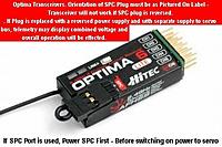
4. SPC Port: View 6ch, 7ch & 9ch Optima Transceiver as being two separate entities; a Receiver & Transmitter with separate Servo Controller.
The two plugs with differences highlighted were attached
SPC connection & Lead Detailed 27Dec10.
Extract: "2. The jumper must be in the SPC slot when a BEC or battery is used for both RX and servos plugged into any of the servo channels separately or "Y".
. a) SPC provides no power to the servos.
. b) If SPC power supply fails, the receiver stops and as no signal is sent to servos, the servos also stop despite any other power source (BEC/Batteries) plugged into a servo channel. "
5.
Which pin is negative on the servos answered 1. above.
Please refer to the shape of plugs and matching shaped slots on the RX case as attached.
No known major brand has the polarity printed/molded on hard case transceivers/receivers as they all rely on the shape of the servo plug/slot
Hitec fully cased transceivers & receivers use polarised plugs and slots which accept both the typical S-01 plugs and also the keyed Futaba "J" plugs
- the key way is also a good indicator as it is always next to the signal lead.
It is possible to force a S-01 plug upside down into a hard case receiver, but no matter as only the signal and negative leads are reversed so there is no damage and the servo simply will not work.
Only soft case receivers have the polarity printed on them, typical example attached.
(as above, servo will not work and no harm if plug upside down and all three pins are lined up)
Aurora A9, Spectra Modules & Optima Transceivers
- FAQ & Undocumented Features
- Mixes, Setups, Tips. {Individual Links often updated}
Alan T.
Alan's Hobby, Model & RC FAQ Web Links
[Right click RCG attachments and open in new window. Button bottom right of IE screen (or _+icons Firefox Toolbar) enables viewing size increase upto 400% for easier reading.]
[*]
 23.0 KB · Views: 462[*]
 45.4 KB · Views: 292[*]
 11.5 KB · Views: 300[*]
 37.4 KB · Views: 54[*]
 124.5 KB · Views: 67[/list]<fieldset class="fieldset"><legend>Attached Files</legend>