Originally Posted by
olnico
That's because you do not use the offset function "0c".
Here is how you should do it. 0c is specifically designed for flaps.
In the example below i used a takeoff position of 15 degrees and offset the control by -15 degrees.
The deflection then becomes 45 down to keep the max deflection of 60 degrees.
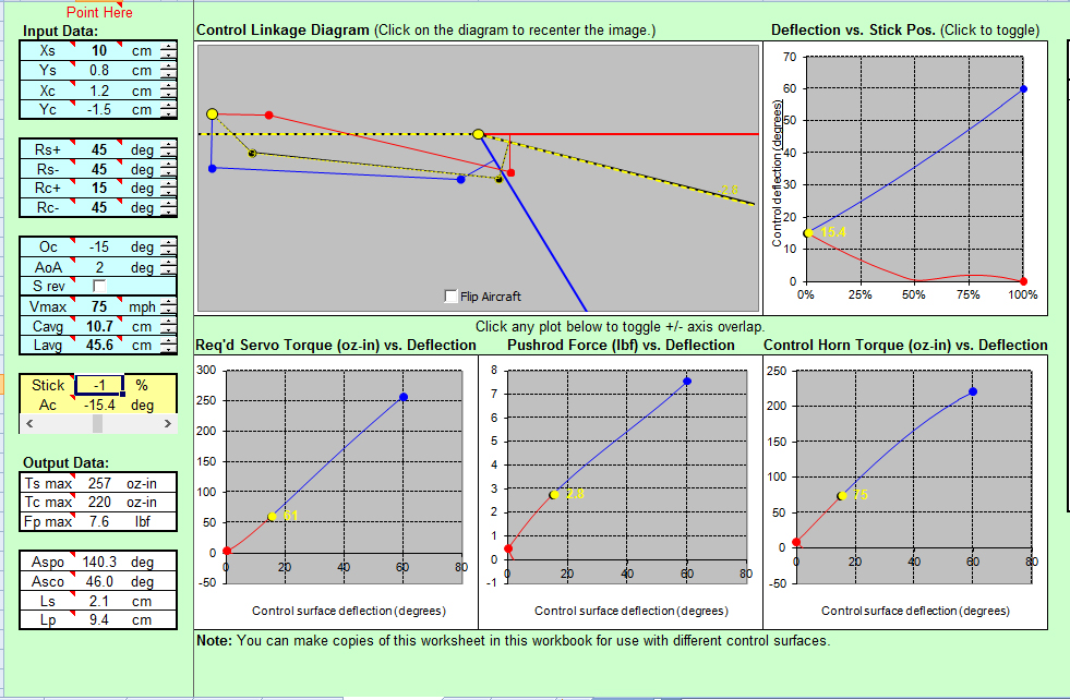
Note that the torque requirement for a deflection of 15 degrees at 75 mph is 61 oz-in. This is good.
As you deflect your flaps towards 60 degrees you want to slow down, as 75 mph would require 257 oz-in of torque from the servo at least.
Thank you Oli for the explanation, is there instructions for the spread sheet that identifies the input parameters and how they are used in the calculations?
I entered the same numbers you used and came up with the same results, however I still have a question, see photo.
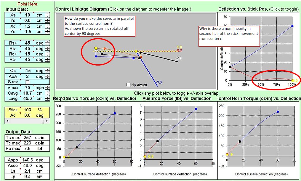
In the cad drawing I have the servo arm drawn as I though it should be which is different than the diagram in the simulation.

It is good to see that the program yields very close results as the drawing, in this case the distance from center line to the tip at full deflection, the Autocad drawing shows 9.7cm and the program shows 9.3 cm, which I think is close...