Originally Posted by
RCISFUN
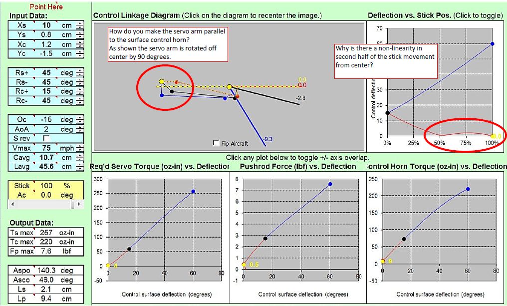
In the cad drawing I have the servo arm drawn as I though it should be which is different than the diagram in the simulation.

The servo arm offsets itself to ensure the cinematics entered ( servo position, horn position and servo/ control deflections ). This is done by simple trigonometry formulas.
There is always one possible solution to ensure a proper cinematics with reasonable inputs.
The red curve is non linear in this example because the servo arm is nearly aligned with the control link for almost all the deflection between 0 degrees and -15 degrees.
The difference between your CAD and the simulation is the servo offset at neutral. Note that this can be changed by entering a different value of Oc.